EP4517111A1 - Entkopplungsmodul - Google Patents
Entkopplungsmodul Download PDFInfo
- Publication number
- EP4517111A1 EP4517111A1 EP23193956.2A EP23193956A EP4517111A1 EP 4517111 A1 EP4517111 A1 EP 4517111A1 EP 23193956 A EP23193956 A EP 23193956A EP 4517111 A1 EP4517111 A1 EP 4517111A1
- Authority
- EP
- European Patent Office
- Prior art keywords
- module
- locking
- module housing
- decoupling
- locking unit
- Prior art date
- Legal status (The legal status is an assumption and is not a legal conclusion. Google has not performed a legal analysis and makes no representation as to the accuracy of the status listed.)
- Pending
Links
Images




Classifications
-
- F—MECHANICAL ENGINEERING; LIGHTING; HEATING; WEAPONS; BLASTING
- F15—FLUID-PRESSURE ACTUATORS; HYDRAULICS OR PNEUMATICS IN GENERAL
- F15B—SYSTEMS ACTING BY MEANS OF FLUIDS IN GENERAL; FLUID-PRESSURE ACTUATORS, e.g. SERVOMOTORS; DETAILS OF FLUID-PRESSURE SYSTEMS, NOT OTHERWISE PROVIDED FOR
- F15B15/00—Fluid-actuated devices for displacing a member from one position to another; Gearing associated therewith
- F15B15/19—Pyrotechnical actuators
-
- B—PERFORMING OPERATIONS; TRANSPORTING
- B60—VEHICLES IN GENERAL
- B60N—SEATS SPECIALLY ADAPTED FOR VEHICLES; VEHICLE PASSENGER ACCOMMODATION NOT OTHERWISE PROVIDED FOR
- B60N2/00—Seats specially adapted for vehicles; Arrangement or mounting of seats in vehicles
- B60N2/24—Seats specially adapted for vehicles; Arrangement or mounting of seats in vehicles for particular purposes or particular vehicles
- B60N2/42—Seats specially adapted for vehicles; Arrangement or mounting of seats in vehicles for particular purposes or particular vehicles the seat constructed to protect the occupant from the effect of abnormal g-forces, e.g. crash or safety seats
- B60N2/427—Seats or parts thereof displaced during a crash
- B60N2/42772—Seats or parts thereof displaced during a crash characterised by the triggering system
- B60N2/42781—Seats or parts thereof displaced during a crash characterised by the triggering system mechanical triggering
-
- B—PERFORMING OPERATIONS; TRANSPORTING
- B60—VEHICLES IN GENERAL
- B60N—SEATS SPECIALLY ADAPTED FOR VEHICLES; VEHICLE PASSENGER ACCOMMODATION NOT OTHERWISE PROVIDED FOR
- B60N2/00—Seats specially adapted for vehicles; Arrangement or mounting of seats in vehicles
- B60N2/24—Seats specially adapted for vehicles; Arrangement or mounting of seats in vehicles for particular purposes or particular vehicles
- B60N2/42—Seats specially adapted for vehicles; Arrangement or mounting of seats in vehicles for particular purposes or particular vehicles the seat constructed to protect the occupant from the effect of abnormal g-forces, e.g. crash or safety seats
- B60N2/427—Seats or parts thereof displaced during a crash
- B60N2/42727—Seats or parts thereof displaced during a crash involving substantially rigid displacement
- B60N2/42736—Seats or parts thereof displaced during a crash involving substantially rigid displacement of the whole seat
-
- B—PERFORMING OPERATIONS; TRANSPORTING
- B60—VEHICLES IN GENERAL
- B60N—SEATS SPECIALLY ADAPTED FOR VEHICLES; VEHICLE PASSENGER ACCOMMODATION NOT OTHERWISE PROVIDED FOR
- B60N2/00—Seats specially adapted for vehicles; Arrangement or mounting of seats in vehicles
- B60N2/02—Seats specially adapted for vehicles; Arrangement or mounting of seats in vehicles the seat or part thereof being movable, e.g. adjustable
- B60N2/04—Seats specially adapted for vehicles; Arrangement or mounting of seats in vehicles the seat or part thereof being movable, e.g. adjustable the whole seat being movable
- B60N2/06—Seats specially adapted for vehicles; Arrangement or mounting of seats in vehicles the seat or part thereof being movable, e.g. adjustable the whole seat being movable slidable
- B60N2/08—Seats specially adapted for vehicles; Arrangement or mounting of seats in vehicles the seat or part thereof being movable, e.g. adjustable the whole seat being movable slidable characterised by the locking device
-
- B—PERFORMING OPERATIONS; TRANSPORTING
- B60—VEHICLES IN GENERAL
- B60N—SEATS SPECIALLY ADAPTED FOR VEHICLES; VEHICLE PASSENGER ACCOMMODATION NOT OTHERWISE PROVIDED FOR
- B60N2/00—Seats specially adapted for vehicles; Arrangement or mounting of seats in vehicles
- B60N2/24—Seats specially adapted for vehicles; Arrangement or mounting of seats in vehicles for particular purposes or particular vehicles
- B60N2/42—Seats specially adapted for vehicles; Arrangement or mounting of seats in vehicles for particular purposes or particular vehicles the seat constructed to protect the occupant from the effect of abnormal g-forces, e.g. crash or safety seats
- B60N2/4207—Seats specially adapted for vehicles; Arrangement or mounting of seats in vehicles for particular purposes or particular vehicles the seat constructed to protect the occupant from the effect of abnormal g-forces, e.g. crash or safety seats characterised by the direction of the g-forces
- B60N2/4214—Seats specially adapted for vehicles; Arrangement or mounting of seats in vehicles for particular purposes or particular vehicles the seat constructed to protect the occupant from the effect of abnormal g-forces, e.g. crash or safety seats characterised by the direction of the g-forces longitudinal
-
- B—PERFORMING OPERATIONS; TRANSPORTING
- B60—VEHICLES IN GENERAL
- B60N—SEATS SPECIALLY ADAPTED FOR VEHICLES; VEHICLE PASSENGER ACCOMMODATION NOT OTHERWISE PROVIDED FOR
- B60N2/00—Seats specially adapted for vehicles; Arrangement or mounting of seats in vehicles
- B60N2/24—Seats specially adapted for vehicles; Arrangement or mounting of seats in vehicles for particular purposes or particular vehicles
- B60N2/42—Seats specially adapted for vehicles; Arrangement or mounting of seats in vehicles for particular purposes or particular vehicles the seat constructed to protect the occupant from the effect of abnormal g-forces, e.g. crash or safety seats
- B60N2/43—Safety locks
-
- E—FIXED CONSTRUCTIONS
- E05—LOCKS; KEYS; WINDOW OR DOOR FITTINGS; SAFES
- E05B—LOCKS; ACCESSORIES THEREFOR; HANDCUFFS
- E05B51/00—Operating or controlling locks or other fastening devices by other non-mechanical means
- E05B51/02—Operating or controlling locks or other fastening devices by other non-mechanical means by pneumatic or hydraulic means
- E05B51/023—Operating or controlling locks or other fastening devices by other non-mechanical means by pneumatic or hydraulic means actuated in response to external pressure, blast or explosion
-
- F—MECHANICAL ENGINEERING; LIGHTING; HEATING; WEAPONS; BLASTING
- F42—AMMUNITION; BLASTING
- F42B—EXPLOSIVE CHARGES, e.g. FOR BLASTING, FIREWORKS, AMMUNITION
- F42B3/00—Blasting cartridges, i.e. case and explosive
- F42B3/006—Explosive bolts; Explosive actuators
-
- B—PERFORMING OPERATIONS; TRANSPORTING
- B60—VEHICLES IN GENERAL
- B60N—SEATS SPECIALLY ADAPTED FOR VEHICLES; VEHICLE PASSENGER ACCOMMODATION NOT OTHERWISE PROVIDED FOR
- B60N2/00—Seats specially adapted for vehicles; Arrangement or mounting of seats in vehicles
- B60N2/24—Seats specially adapted for vehicles; Arrangement or mounting of seats in vehicles for particular purposes or particular vehicles
- B60N2/42—Seats specially adapted for vehicles; Arrangement or mounting of seats in vehicles for particular purposes or particular vehicles the seat constructed to protect the occupant from the effect of abnormal g-forces, e.g. crash or safety seats
- B60N2/427—Seats or parts thereof displaced during a crash
-
- B—PERFORMING OPERATIONS; TRANSPORTING
- B60—VEHICLES IN GENERAL
- B60N—SEATS SPECIALLY ADAPTED FOR VEHICLES; VEHICLE PASSENGER ACCOMMODATION NOT OTHERWISE PROVIDED FOR
- B60N2/00—Seats specially adapted for vehicles; Arrangement or mounting of seats in vehicles
- B60N2/24—Seats specially adapted for vehicles; Arrangement or mounting of seats in vehicles for particular purposes or particular vehicles
- B60N2/42—Seats specially adapted for vehicles; Arrangement or mounting of seats in vehicles for particular purposes or particular vehicles the seat constructed to protect the occupant from the effect of abnormal g-forces, e.g. crash or safety seats
- B60N2/427—Seats or parts thereof displaced during a crash
- B60N2/42772—Seats or parts thereof displaced during a crash characterised by the triggering system
- B60N2/4279—Seats or parts thereof displaced during a crash characterised by the triggering system electric or electronic triggering
-
- F—MECHANICAL ENGINEERING; LIGHTING; HEATING; WEAPONS; BLASTING
- F16—ENGINEERING ELEMENTS AND UNITS; GENERAL MEASURES FOR PRODUCING AND MAINTAINING EFFECTIVE FUNCTIONING OF MACHINES OR INSTALLATIONS; THERMAL INSULATION IN GENERAL
- F16B—DEVICES FOR FASTENING OR SECURING CONSTRUCTIONAL ELEMENTS OR MACHINE PARTS TOGETHER, e.g. NAILS, BOLTS, CIRCLIPS, CLAMPS, CLIPS OR WEDGES; JOINTS OR JOINTING
- F16B19/00—Bolts without screw-thread; Pins, including deformable elements; Rivets
- F16B19/02—Bolts or sleeves for positioning of machine parts, e.g. notched taper pins, fitting pins, sleeves, eccentric positioning rings
Definitions
- the invention relates to a decoupling module for two detachably connected components and to a vehicle seat with such a decoupling module.
- the invention is based on the object of improving a decoupling module of the type mentioned at the outset, which in particular also decouples under load, and of providing a corresponding vehicle seat with such an improved decoupling module.
- the first-mentioned object is achieved according to the invention by a decoupling module with the features of claim 1.
- the second-mentioned object is solved according to the invention by a vehicle seat with the features of claim 10.
- the decoupling module according to the invention for two components that are detachably connected to one another comprises at least one module housing with a coupling interface, in particular an external first one, in particular for coupling to one of the components, and a cavity, a locking unit that is mounted axially movably in the module housing on the one hand and protrudes at least partially from the module housing in an initial state, in particular in order to detachably lock or couple the two components to one another, and a drive unit that is arranged in a fixed position in the module housing on the other hand, wherein the locking unit and the drive unit are designed to interact in such a way that when the drive unit is triggered or ignited, the locking unit can be or is suddenly directly acted upon by a pressure surge spreading or building up in the cavity and moves into the module housing.
- the locking unit is axially movable along a linear axis and moves linearly into the module housing.
- the decoupling module is designed with the locking unit and the drive unit, which interact with each other, as a linear locking release, in particular a linear bolt release or a linear latch release.
- the spreading pressure surge or a building up integral pressure can be generated, for example, by a gas or gas mixture of the drive unit introduced into the cavity.
- the cavity is also referred to as the gas space. Because the pressure surge is applied directly to the locking unit, a particularly compact decoupling module with a high working force and a high working pressure is possible.
- the module housing, locking unit and drive unit can be arranged coaxially to one another, for example.
- the module housing, locking unit and drive unit can each be oriented and arranged coaxially to their longitudinal axes.
- the module housing has a cavity, in particular a cup-shaped cavity, in which the locking unit and the drive unit are arranged coaxially to one another.
- the module housing, the locking unit and the drive unit can each be arranged at least partially overlapping and coaxially to one another, for example.
- the coaxial arrangement of the components of the decoupling module enables simple production and a simple, modular and particularly compact structure of the decoupling module.
- the drive unit can be designed, for example, as a pyrotechnic device.
- the drive unit can be supported, in particular, via its front sides on the one hand on the module housing and on the other hand on the locking unit.
- the decoupling module in particular the module housing, for example the module cover, can furthermore have a second, for example external, coupling interface.
- the first coupling interface of the module housing can be designed as an external thread, for example.
- the second coupling interface of the module housing can be designed as a nut, in particular a hexagon profile or a hexagon nut, for example. This allows the decoupling module to be easily attached to one of the two components to be connected without tools using only one coupling interface. or with a wrench for two coupling interfaces.
- an axial end of the drive unit can be designed as a module cover which is positively and/or non-positively connected to the module housing when the decoupling module is in the assembled state.
- the module cover can be crimped, screwed or the like to the module housing.
- the module housing and the drive unit can be connected to one another in such a way that they are sealed gas-tight to the outside when assembled.
- the module housing can in particular be sealed gas-tight to the outside in such a way that when the drive unit is triggered, the locking unit is held or is held in the retracted position at least temporarily.
- the locking unit can be designed to be lockable in the retracted position.
- the module cover can be arranged to partially overlap the module housing.
- the module housing and the module cover can be telescopically inserted into one another.
- the module cover can be partially slipped over an outer wall of the module housing.
- an outer wall of the module housing can be partially slipped over the module cover.
- the locking unit can, for example, comprise a locking section and a pressure application section which can be subjected to the pressure surge when the drive unit is triggered or ignited, so that the locking unit moves into the module housing at an accelerated rate and decouples the two components from each other.
- the location of the force application on the locking unit can be designed variably, in particular with regard to geometric shape, orientation and arrangement of the locking unit relative to the drive unit and can be influenced by these parameters.
- the pressure-acting section can be designed, for example, as a cylindrical hollow chamber or cup-shaped hollow chamber with at least one recess.
- the at least one recess can be designed, for example, as a gas passage, a through-flow opening, an overflow opening, an overflow channel or the like.
- the pressure-acting section can comprise several recesses that are distributed symmetrically.
- the locking section can be designed, for example, as a shaft end, a latch, a pin or another suitable locking element.
- the locking element can be pre-tensioned in a connected state of the two components by means of a force accumulator, in particular a spring element, for lockingly connecting the two components.
- the module housing can furthermore have an opening, for example in a housing base for a shaft end of the locking unit, through which the shaft end protrudes at least partially from the module housing in the connected state in order to connect the two components to one another in a locked manner or to keep them locked to one another.
- the vehicle seat according to the invention comprises the decoupling module described above.
- the invention provides an axisymmetric decoupling module.
- the axially symmetrical decoupling module has, on the one hand, the first coupling interface of the module housing designed as a screw thread with an opening for the locking unit designed as a pin, pin or shaft end and, on the other hand, the second coupling interface designed, for example, as a hexagon or nut.
- Such a decoupling module with at least one of the coupling interfaces allows this decoupling module to be easily screwed into one of the components.
- a in the Figure 1 The schematically illustrated vehicle seat 100 is subsequently produced using three perpendicular Spatial directions are described.
- a longitudinal direction x runs largely horizontally and preferably parallel to a vehicle longitudinal direction that corresponds to the normal direction of travel of the vehicle.
- a transverse direction y running perpendicular to the longitudinal direction x is also aligned horizontally in the vehicle and runs parallel to a vehicle transverse direction.
- a vertical direction z runs perpendicular to the longitudinal direction x and perpendicular to the transverse direction y.
- the vertical direction z preferably runs parallel to a vehicle vertical axis.
- the position and direction information used refer to a viewing direction of an occupant sitting in the vehicle seat 100 in a normal sitting position, with the vehicle seat 100 installed in the vehicle, in a position of use suitable for transporting people with the backrest 104 upright and aligned in the direction of travel as usual.
- the vehicle seat 100 can also be installed or moved in a different orientation, for example transversely to the direction of travel.
- the vehicle seat 100 is constructed mirror-symmetrically to a plane running perpendicular to the transverse direction y.
- the backrest 104 can be pivotably arranged on a seat part 102 of the vehicle seat 100.
- the vehicle seat 100 can optionally comprise a fitting 106, in particular an adjustment fitting, rotary fitting, locking fitting or wobble fitting.
- the position and direction information used such as radial, axial and circumferential, refer to a rotation axis 108 of the fitting 106.
- Radial means perpendicular to the rotation axis 108.
- Axial means in the direction or parallel to the rotation axis 108.
- the vehicle seat 100 can optionally comprise a longitudinal adjustment device 110.
- the longitudinal adjustment device 110 comprises, for example, a rail arrangement 112 with a first rail element 114 and a second rail element 116.
- the first rail element 114 is adjustable in the longitudinal direction x relative to the second rail element 116.
- the first rail element 114 is fastened to the seat part 102.
- the second rail element 116 is fastened to a structural element of a vehicle, for example a vehicle floor.
- the first rail element 114 is referred to as the upper rail 114 in the following description.
- This upper rail 114 also called a running rail or slide
- the second rail element 116 is referred to below as the lower rail 116.
- the lower rail 116 is fixed and is connected, for example, to the floor of a vehicle.
- a decoupling module 200 can be provided for the sudden decoupler, for example, of components of the vehicle seat 100, in particular of components of the longitudinal adjustment device 110, in the event of a collision.
- Figure 2 shows an exploded view of a decoupling module 200 according to the invention according to a first embodiment.
- the decoupling module 200 comprises at least one module housing 202.
- the module housing 202 is designed as a hollow body.
- the module housing 202 has a cavity 204.
- the cavity 204 is in particular hollow-cylindrical or cup-shaped.
- the module housing 202 can be modular.
- the module housing 202 can have a
- the module housing 202 further comprises a first coupling interface 202.3.
- the first coupling interface 202.3 is an external interface for coupling to one of the two components, which can be or are locked together releasably by means of the decoupling module 200.
- the first coupling interface 202.3 is designed, for example, as an external thread.
- the first coupling interface 202.3 is designed, for example, as an external thread on the outside of a first front end 202.4.
- the decoupling module 200 can thus be easily screwed into or onto one of the two components.
- the decoupling module 200 further comprises a locking unit 206 and a drive unit 208.
- the locking unit 206 is mounted axially movably in the module housing 202. In an initial state, the locking unit 206 protrudes at least partially from the module housing 202, in particular in order to detachably lock or couple the two components together, as in Figure 4 shown.
- the drive unit 208 is arranged stationary in the module housing 202.
- the locking unit 206 and the drive unit 208 are designed to interact in such a way that when the drive unit 208 is triggered or ignited, the locking unit 206 can be or is suddenly directly acted upon by a pressure surge spreading or building up in the cavity 204 and moves into the module housing 202.
- the locking unit 206 is axially movable along a linear axis 210 and moves linearly into the module housing 202 when the locking unit 208 is triggered.
- the decoupling module 200 is designed with the locking unit 206 and the drive unit 208, which interact with each other, as a linear locking trigger, in particular a linear bolt trigger or a linear latch trigger.
- the drive unit 208 can be designed, for example, as a pyrotechnic device, for example a gas generator with a pyrotechnic igniter.
- the drive unit 208 can be supported, in particular via its end faces, on the one hand on the module housing 202, in particular on the module cover 202.2, and on the other hand on the locking unit 206.
- the module cover 202.2 can have a receptacle 202.9 for the drive unit 208 protruding in the direction of the module base body 202.1.
- the module housing 202 and the drive unit 208 can be connected to one another in such a way that they are sealed gas-tight to the outside when assembled.
- at least one seal 212 can be provided.
- the seal 212 comprises, for example, two first sealing rings 212.1, which are arranged between the locking unit 206 and the module housing 202.
- the seal 212 can, for example, additionally or alternatively be designed as a second sealing ring 212.2, which is arranged on the outside of the drive unit 208 and seals the module cover 202.2 to the outside.
- the locking unit 206 can, for example, comprise a locking section 206.1 and a pressure application section 206.2, which can be subjected to the pressure surge when the drive unit 208 is triggered or ignited, so that the locking unit 206 moves into the module housing 202 at an accelerated rate and decouples the two components from one another.
- the location of the force acting on the locking unit 206, in particular on the pressure application section 206.2, can be variable, in particular with regard to the geometric shape, orientation and arrangement of the locking unit 206 relative to the drive unit 208, and can be influenced by these parameters.
- the pressure application section 206.2 can be designed, for example, as a cylindrical hollow chamber or cup-shaped hollow chamber with at least one Recess 206.3 can be formed.
- the at least one recess 206.3 can be formed, for example, as a gas passage 206.4.
- the recess 206.3 can be formed as a through-flow opening, an overflow opening or the like.
- the pressure-acting section 206.2 can comprise several recesses 206.3 that are distributed symmetrically.
- the locking section 206.1 can be designed, for example, as a shaft end 206.5. Alternatively, the locking section 206.1 can be designed as a latch, a pin or another suitable locking element.
- the locking section 206.1 can be pre-tensioned in a connected state of the two components by means of a force accumulator 214, in particular a spring element, in particular a helical spring, for lockingly connecting the two components.
- the module housing 202 can furthermore have an opening 202.8, for example in a housing base 202.7 for a shaft end 206.5 of the locking unit 206, in particular for a bolt-shaped or pin-shaped shaft end 206.5, through which the shaft end 206.5 protrudes at least partially from the module housing 202 in the connected state in order to connect the two components to one another in a locked manner or to keep them locked to one another.
- an opening 202.8 for example in a housing base 202.7 for a shaft end 206.5 of the locking unit 206, in particular for a bolt-shaped or pin-shaped shaft end 206.5, through which the shaft end 206.5 protrudes at least partially from the module housing 202 in the connected state in order to connect the two components to one another in a locked manner or to keep them locked to one another.
- Figure 3 shows a perspective and partially cutaway view of the decoupling module 200 of the first embodiment in the assembled state.
- the module cover 202.2 can be arranged partially overlapping with the module base body 202.1.
- the module base body 202.1 and the module cover 202.2 can be telescopically inserted into one another.
- an outer wall of the module base body 202.1 can be partially placed over the module cover 202.2.
- the receptacle 202.9 of the module cover 202.2 is designed on the inside to correspond to an external shape and/or external dimensions of the drive unit 208. On the outside, the receptacle 202.9 is designed in such a way that the energy accumulator 214 can be supported.
- the receptacle 202.9 has at least one shoulder 202.10 on the outside.
- the receptacle 202.9 can have a groove 202.11 for the second sealing ring 212.2.
- the module cover 202.2 can have a fastening flange 202.12, which is arranged in a form-fitting and/or force-fitting manner in a fastening groove 202.13 of the module base body 202.1.
- the drive unit 208 When the drive unit 208 is ignited, it generates a pressure surge or an integral pressure through a gas 216 or gas mixture introduced into the cavity 204.
- the cavity 204 is also referred to as the gas space.
- the pressure-acting section 206.2 of the locking unit 206 is subjected to the gas 216. The fact that the pressure surge acts directly on the locking unit 206 enables a particularly compact decoupling module 200 with a high working force and a high working pressure.
- the locking unit 206 moves linearly into the module housing 202 as a result of the applied pressure surge and forms a linear bolt release or a linear latch release.
- the module housing 202, the locking unit 206 and the drive unit 208 can be arranged coaxially to one another.
- the module housing 202, locking unit 206 and drive unit 208 are each oriented and arranged coaxially to their longitudinal axes and the linear axis 210.
- module housing 202 the locking unit 206 and the drive unit 208 can, for example, each be arranged at least partially overlapping and coaxial with each other.
- Figure 4 shows a perspective view of the decoupling module 200 of the first embodiment in the assembled state.
- the energy accumulator 214 is supported on the one hand on the shoulder 202.10 of the module cover 202.2 and on the other hand on a front end of the pressure application section 206.2 of the locking unit 206.
- the fastening flange 202.12 of the module cover 202.2 can additionally be provided with an anti-twist device 202.14.
- the anti-twist device 202.14 can be formed, for example, from at least one radially protruding rib and a corresponding slot on an inner side of the module base body 202.1. In the assembled state, the rib engages in the slot in a rotationally fixed manner. This can assist in screwing the decoupling module 200 into one of the components, in particular an internal thread, via the first coupling interface 202.3, in particular an external thread, by means of a tool engaging in the second coupling interface 202.5, in particular a hexagon or a nut element.
- Figure 5 shows a perspective view of the module cover 202.2 with the drive unit 208, which are pre-assembled together.
- the module cover 202.2 has a connection opening 202.15 for the drive unit 208 at its front end.
- a connection unit 208.1 for connecting electrical cables and/or ignition cables protrudes into 202.15.
- the connection unit 208.1 is arranged in the connection opening 202.15 and is freely accessible from the outside.
- the anti-twisting device 202.14 can have a plurality of ribs that are symmetrically distributed below the mounting flange 202.12.
- Figure 6 shows a perspective view of the locking unit 206.
- the locking unit 206 has the locking section 206.1 with the shaft end 206.5, which connects the two components to one another in a locking manner (not shown), and the pressure-acting section 206.2 with the recesses 206.3, which are designed as a gas passage 206.4.
- the pressure application section 206.2 is cup-shaped and comprises a number of alternately arranged separating webs 206.6 and recesses 206.3.
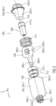
- Figure 7 shows an exploded view of a decoupling module 300 according to the invention according to a second embodiment.
- the decoupling module 300 differs from the decoupling module 200 only in the shape of the locking unit 306 and the module housing 302. All other structural features and functions of the decoupling module 300 are analogous to the decoupling module 200, as previously described.
- the decoupling module 300 has as recesses 306.3 gas channels 306.4.
- the gas channels 306.4 can be arranged, for example, on an outer side of the inwardly projecting receptacle 302.9 of the module housing 302. Alternatively or additionally, gas channels 306.4 can be formed on an inner side of the hollow cylindrical pressure-acting section 306.2 of the locking unit 306.
- the locking section 306.1 protrudes from the pressure application section 306.2 in the direction of the module base body 302.1.
- the decoupling module 300 is sealed gas-tight to the outside.
- the drive unit 308 is arranged and held in the module cover 302.2 in a similar manner in a stationary manner, in particular in a form-fitting and/or force-fitting manner.
- Figure 8 shows an exploded view of a decoupling module according to the invention according to a third embodiment and Figure 9 shows the decoupling module 400 after Figure 8 in assembled state.
- the decoupling module 400 differs from the decoupling module 200 or 300 only in the structure of the locking unit 306. All other structural features and functions of the decoupling module 400 are analogous to the decoupling module 200 or 300, as previously described.
- the locking unit 406 of the decoupling module 400 is designed in several parts.
- the locking unit 406 comprises a separate locking section 406.1, which is designed as a separate pin or stud.
- the pressure application section 406.2 is also designed separately.
- the Pressure device section 406.2 is designed as an inner hollow cylinder or inner cylindrical housing.
- the pin-shaped or pin-shaped locking section 406.1 can be inserted into the pressure-acting section 406.2.
- the locking section 406.1 has such a shape and/or such dimensions that, when inserted in the pressure-acting section 406.2, it protrudes through an opening 406.3 and protrudes in the direction of the module base body 402.1 of the module housing 402 and protrudes through a housing opening 402.3 aligned with the opening 406.3 and protrudes outward from the module base body 402.1.
- the module base body 402.1 is a hollow cylinder and forms an outer section of the module housing 402.
- the module base body 402.1 can be closed with the module cover 402.2 on the side opposite to the housing opening 402.3.
- Two seals 412 designed as sealing rings 412.1 are provided to seal the module housing 402.
- the decoupling module 400 is sealed gas-tight to the outside by means of the seal 412 designed as sealing rings 412.1.
- the drive unit 408 is arranged and held in the module cover 402.2 in a similar manner in a stationary manner, in particular in a form-fitting and/or force-fitting manner.
- the locking section 406.1 can be mounted in a connected state of the two components by means of a force accumulator 414, in particular a spring element, in particular a helical spring, for lockingly connecting the two components in a pre-tensioned manner in the module base body 402.1, as in Figures 11 and 12 shown.
- a force accumulator 414 in particular a spring element, in particular a helical spring
- the decoupling module 400 can also comprise, for example, an elongated connection element 416.
- the connection element 416 is designed as an interface or adapter for connecting lines or cables to the drive unit 408.
- Figure 9 shows a perspective view of the decoupling module 400 according to Figure 8 in the assembled state with the outer module cover 402.2, the outer module base body 402.1 and the pin-shaped or pin-shaped locking section 406.1 of the locking unit 406 protruding therefrom.
- FIG 10 shows schematically in perspective the multi-part locking unit 406 in the assembled state.
- the multi-part locking unit 406 comprises the pin-shaped locking section 406.1 and the cylindrical pressure-acting section 406.2.
- the pressure-acting section 406.2 comprises instead of the recesses 206.3 of the decoupling module 200 designed as gas passages 206.4
- Gas channels 406.4 designed as recesses in an analogous manner to the gas channels 306.4 of the decoupling module 300 according to Figure 7 .
- the gas channels 406.4 can, for example, be formed on an inner side of the hollow cylindrical pressure-acting section 406.2 of the locking unit 406.
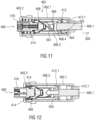
- Figure 11 shows schematically in section the decoupling module 400 according to Figure 9 before or when the drive unit 408 is triggered.
- the energy accumulator 414 is in the relaxed state or partially relaxed state and holds or presses the locking unit 406 in the locking direction 500 against the seal 412 in the module housing 402.
- a pressure surge is generated against the locking section 406.1 by a gas or gas mixture introduced into the cavity 404 through the gas channels 406.4 according to arrows 502, in particular into the cavity 404 sealed to the outside by means of the sealing rings 412.1.
- the pressure-acting section 406.2 is provided with the gas channels 406.4 in the direction of the cavity 404, which Figure 10 are shown.
- Figure 12 shows schematically in section the decoupling module 400 according to Figures 9 and 10 after the drive unit 408 has been triggered and in the unlocked state.
- Figure 13 shows a schematic perspective view of another decoupling module 600 in the assembled state with a crimped module housing 602. All of the previously described screwed module housings 202, 302 and 402 can have a crimped or crimpable module housing 202, 302 or 402 instead of the respective module cover 202.2, 302.2 and 402.2, which can be screwed or is screwed to the associated module base body 202.1, 302.1 and 402.1.
- the respective module housing 202, 302 and 402 can be arranged analogously to the module housing 602 according to Figure 13
- the module housing 602 is designed such that it can be plastically deformed, in particular squeezed, flanged or folded, by means of a crimp band 602.4 and can be tightly closed to the outside.
Landscapes
- Engineering & Computer Science (AREA)
- Mechanical Engineering (AREA)
- Aviation & Aerospace Engineering (AREA)
- Transportation (AREA)
- General Engineering & Computer Science (AREA)
- Chemical & Material Sciences (AREA)
- Analytical Chemistry (AREA)
- Physics & Mathematics (AREA)
- Fluid Mechanics (AREA)
- Air Bags (AREA)
- Connection Of Plates (AREA)
Abstract
Description
- Die Erfindung betrifft einen Entkopplungsmodul für zwei lösbar miteinander verbundene Bauteile sowie einen Fahrzeugsitz mit einem solchen Entkopplungsmodul.
- Aus der der
DE 10 2009 033 721 B4 und derDE 10 2011 014 869 A1 sind Befestigungsvorrichtungen zur lösbaren Befestigung eines Elements an einem fahrzeugfesten Bauteil bekannt. - Der Erfindung liegt die Aufgabe zu Grunde, ein Entkopplungsmodul der eingangs genannten Art zu verbessern, der insbesondere auch unter Last entkoppelt, sowie einen entsprechenden Fahrzeugsitz mit einem solchen verbesserten Entkopplungsmodul bereitzustellen.
- Die erstgenannte Aufgabe wird erfindungsgemäß gelöst durch ein Entkopplungsmodul mit den Merkmalen des Anspruchs 1. Die zweitgenannte Aufgabe wird erfindungsgemäß gelöst durch einen Fahrzeugsitz mit den Merkmalen des Anspruchs 10.
- Vorteilhafte Ausgestaltungen, welche einzeln oder in Kombination miteinander eingesetzt werden können, sind Gegenstand der Unteransprüche.
- Das erfindungsgemäße Entkopplungsmodul für zwei lösbar miteinander verbundene Bauteile umfasst zumindest ein Modulgehäuse mit einer, insbesondere äußeren ersten, Kopplungsschnittstelle, insbesondere zur Kopplung an eines der Bauteile, und einen Hohlraum, eine Arretierungseinheit, die einerseits in dem Modulgehäuse axial beweglich gelagert ist und in einem Ausgangszustand zumindest teilweise aus dem Modulgehäuse ragt, insbesondere um die beiden Bauteile lösbar miteinander zu arretieren oder zu koppeln, und eine Antriebseinheit, die andererseits in dem Modulgehäuse ortsfest angeordnet ist, wobei die Arretierungseinheit und die Antriebseinheit derart zusammenwirkend ausgebildet sind, dass bei Auslösung oder Zündung der Antriebseinheit die Arretierungseinheit schlagartig von einem sich in dem Hohlraum ausbreitenden oder aufbauenden Druckstoß direkt beaufschlagbar ist oder beaufschlagt wird und sich in das Modulgehäuse hineinbewegt. Die Arretierungseinheit ist axial entlang einer linearen Achse bewegbar und bewegt sich linear in das Modulgehäuse hinein. Mit anderen Worten: Das Entkopplungsmodul ist mit der Arretierungseinheit und der Antriebseinheit, die miteinander zusammenwirken, als eine lineare Arretierungsauslösung, insbesondere eine lineare Bolzenauslösung oder eine lineare Riegelauslösung, ausgebildet.
- Der sich ausbreitende Druckstoß oder ein sich aufbauender integraler Druck kann beispielsweise durch ein in den Hohlraum eingeleitetes Gas oder Gasgemisch der Antriebseinheit erzeugt werden. Der Hohlraum wird auch als Gasraum bezeichnet. Dadurch, dass der Druckstoß direkt auf die Arretierungseinheit wirkt, ist ein besonders kompaktes Entkopplungsmodul mit einer hohen Arbeitskraft und einem hohen Arbeitsdruck ermöglicht.
- Darüber hinaus können Modulgehäuse, Arretierungseinheit und Antriebseinheit beispielsweise koaxial zueinander angeordnet sein. Vorzugsweise können Modulgehäuse, Arretierungseinheit und Antriebseinheit jeweils koaxial zu deren Längsachsen zueinander orientiert und angeordnet sein. Insbesondere weist das Modulgehäuse einen, insbesondere becherförmigen, Hohlraum auf, in welchem die Arretierungseinheit und die Antriebseinheit zueinander koaxial angeordnet sind. Darüber hinaus können das Modulgehäuse, die Arretierungseinheit und die Antriebseinheit beispielsweise jeweils wenigstens abschnittsweise überlappend und koaxial zueinander angeordnet sein. Die koaxiale Anordnung der Komponenten des Entkopplungsmoduls ermöglichen eine einfache Fertigung und einen einfachen, modularen und besonders kompakten Aufbau des Entkopplungsmoduls.
- Die Antriebseinheit kann beispielsweise als eine pyrotechnische Einrichtung ausgebildet sein. Die Antriebseinheit kann insbesondere über ihre Stirnseiten einerseits am Modulgehäuse und andererseits an der Arretierungseinheit abgestützt sein.
- Das Entkopplungsmodul, insbesondere das Modulgehäuse, zum Beispiel der Moduldeckel, kann darüber hinaus eine zweite, beispielsweise äußere, Kopplungsschnittstelle aufweisen.
- Die erste Kopplungsschnittstelle des Modulgehäuses kann beispielsweise als ein Außengewinde ausgebildet sein. Die zweite Kopplungsschnittstelle des Modulgehäuses kann beispielsweise als eine Mutter, insbesondere ein Sechskantprofil oder eine Sechskantmutter, ausgebildet sein. Dadurch kann das Entkopplungsmodul in einfacher Art und Weise an einem der beiden zu verbindenden Bauteile werkzeuglos bei nur einer Kopplungsschnittstelle oder mit einem Schraubenschlüssel bei zwei Kopplungsschnittstellen befestigt werden.
- Beispielsweise kann ein axiales Ende der Antriebseinheit als ein Moduldeckel ausgebildet sein, der in einem zusammengebauten Zustand des Entkopplungsmoduls mit dem Modulgehäuse formschlüssig und/oder kraftschlüssig verbunden ist. Beispielsweise kann der Moduldeckel mit dem Modulgehäuse verkrimpt, verschraubt oder dergleichen sein.
- Beispielsweise können das Modulgehäuse und die Antriebseinheit derart miteinander verbunden sein, dass diese im zusammengebauten Zustand gasdicht nach außen abgedichtet sind. Das Modulgehäuse kann insbesondere nach außen derart gasdicht abgeschlossen sein, dass bei ausgelöster Antriebseinheit die Arretierungseinheit zumindest zeitweise in der eingezogenen Stellung gehalten wird oder gehalten ist. Alternativ kann die Arretierungseinheit in eingezogener Stellung arretierbar ausgebildet sein.
- Darüber hinaus kann der Moduldeckel teilweise überlappend mit dem Modulgehäuse angeordnet sein. Beispielsweise können das Modulgehäuse und der Moduldeckel teleskopisch ineinander gesetzt sein. Beispielsweise kann der Moduldeckel über eine Außenwand des Modulgehäuses teilweise stülpbar sein. Alternativ kann eine Außenwand des Modulgehäuses über den Moduldeckel teilweise stülpbar sein. Eine solche Ausgestaltung ermöglicht eine variable Einstellung des modularen Gehäuses des Entkopplungsmoduls und somit unterschiedliche Modulgrößen und Modulabmessungen.
- Die Arretierungseinheit kann beispielsweise einen Arretierungsabschnitt und einen Druckeinwirkungsabschnitt umfassen, der bei Auslösung oder Zündung der Antriebseinheit mit dem Druckstoß beaufschlagbar ist, so dass sich die Arretierungseinheit beschleunigt in das Modulgehäuse hineinbewegt und die beiden Bauteile voneinander entkoppelt. Der Ort der Krafteinwirkung auf die Arretierungseinheit kann variabel insbesondere in Bezug auf geometrische Gestalt, Ausrichtung und Anordnung der Arretierungseinheit relativ zur Antriebseinheit ausgebildet sein und von diesen Parametern beeinflusst werden.
- Der Druckeinwirkungsabschnitt kann beispielsweise als eine zylindrische Hohlkammer oder becherförmige Hohlkammer mit mindestens einer Ausnehmung ausgebildet sein. Die mindestens eine Ausnehmung kann beispielsweise als ein Gasdurchlass, eine Durchströmöffnung, eine Überströmöffnung, ein Überströmkanal oder dergleichen ausgebildet sein. Beispielsweise kann der Druckeinwirkungsabschnitt mehrere Ausnehmungen umfassen, die symmetrisch verteilt sind.
- Der Arretierungsabschnitt kann beispielsweise als ein Schaftende, ein Riegel, ein Stift oder ein anderes geeignetes Arretierungselement ausgebildet sein. Das Arretierungselement kann in einem verbundenen Zustand der beiden Bauteile mittels eines Kraftspeichers, insbesondere einem Federelement, zum arretierenden Verbinden der beiden Bauteile vorgespannt gelagert sein.
- Das Modulgehäuse kann darüber hinaus beispielsweise in einem Gehäuseboden für ein Schaftende der Arretierungseinheit eine Öffnung aufweisen, durch welche das Schaftende in dem verbundenen Zustand zumindest bereichsweise aus dem Modulgehäuse herausragt, um die beiden Bauteile arretiert miteinander zu verbinden oder arretiert miteinander zu halten.
- Der erfindungsgemäße Fahrzeugsitz umfasst das zuvor beschriebene Entkopplungsmodul.
- Zusammenfassend und mit anderen Worten ausgedrückt ist durch die Erfindung ein achssymmetrisches Entkopplungsmodul bereitgestellt. Das achssymmetrische Entkopplungsmodul weist einerseits die erste als Einschraubgewinde ausgebildete Kopplungsschnittstelle des Modulgehäuses mit einer Öffnung für die als Pin, Stift oder Schaftende ausgebildete Arretierungseinheit und andererseits die zweite, beispielsweise als Sechskant oder Mutter, ausgebildete Kopplungsschnittstelle auf.
- Durch ein solches Entkopplungsmodul mit mindestens einer der Kopplungsschnittstellen kann dieses Entkopplungsmodul einfach an einem der Bauteile eingeschraubt werden.
- Im Folgenden ist die Erfindung anhand von in den Figuren dargestellten vorteilhaften Ausführungsbeispielen näher erläutert. Die Erfindung ist jedoch nicht auf diese Ausführungsbeispiele beschränkt. Es zeigen:
- Fig. 1:
- in schematischer Darstellung einen Fahrzeugsitz mit einer Längsverstelleinrichtung,
- Fig. 2:
- eine Explosionsdarstellung eines erfindungsgemäßen Entkopplungsmoduls gemäß eines ersten Ausführungsbeispiels,
- Fig. 3:
- eine perspektivische Darstellung des Entkopplungsmoduls des ersten Ausführungsbeispiels im zusammengebauten Zustand,
- Fig. 4:
- eine perspektivische Darstellung des Entkopplungsmoduls des ersten Ausführungsbeispiels im zusammengebauten Zustand,
- Fig. 5:
- eine perspektivische Darstellung eines Moduldeckels mit einer vormontierten Antriebseinheit,
- Fig. 6:
- eine perspektivische Darstellung einer Arretierungseinheit des Entkopplungsmoduls des ersten Ausführungsbeispiels,
- Fig. 7:
- eine Explosionsdarstellung eines erfindungsgemäßen Entkopplungsmoduls gemäß eines zweiten Ausführungsbeispiels,
- Fig. 8:
- eine Explosionsdarstellung eines erfindungsgemäßen Entkopplungsmoduls gemäß eines dritten Ausführungsbeispiels,
- Fig. 9:
- eine perspektivische Darstellung des Entkopplungsmoduls nach
Figur 8 im zusammengebauten Zustand, - Fig. 10:
- schematisch in perspektivischer Darstellung eine mehrteilige Arretierungseinheit im zusammengesetzten Zustand,
- Fig. 11:
- schematisch in Schnittdarstellung das Entkopplungsmodul nach
Figur 9 vor einem oder bei einem Auslösen einer Antriebseinheit, - Fig. 12:
- schematisch in Schnittdarstellung das Entkopplungsmodul nach
Figur 9 nach ausgelöster Antriebseinheit, und - Fig. 13:
- schematisch in perspektivischer Darstellung das Entkopplungsmodul im zusammengebauten Zustand mit einem gecrimpten Modulgehäuse anstelle eines verschraubten Modulgehäuses.
- Einander entsprechende Teile sind in allen Figuren mit den gleichen Bezugszeichen versehen.
- Ein in der
Figur 1 schematisch dargestellter Fahrzeugsitz 100 wird nachfolgend unter Verwendung von drei senkrecht zueinander verlaufenden Raumrichtungen beschrieben. Eine Längsrichtung x verläuft bei einem im Fahrzeug eingebauten Fahrzeugsitz 100 weitgehend horizontal und vorzugsweise parallel zu einer Fahrzeuglängsrichtung, die der gewöhnlichen Fahrtrichtung des Fahrzeugs entspricht. Eine zu der Längsrichtung x senkrecht verlaufende Querrichtung y ist im Fahrzeug ebenfalls horizontal ausgerichtet und verläuft parallel zu einer Fahrzeugquerrichtung. Eine Vertikalrichtung z verläuft senkrecht zu der Längsrichtung x und senkrecht zu der Querrichtung y. Bei einem im Fahrzeug eingebauten Fahrzeugsitz 100 verläuft die Vertikalrichtung z vorzugsweise parallel zu einer Fahrzeughochachse. - Die verwendeten Positionsangaben und Richtungsangaben, wie beispielsweise vorne, hinten, oben und unten beziehen sich auf eine Blickrichtung eines im Fahrzeugsitz 100 sitzenden Insassen in normaler Sitzposition, wobei der Fahrzeugsitz 100 im Fahrzeug eingebaut, in einer zur Personenbeförderung geeigneten Gebrauchsposition mit aufrecht stehender Rückenlehne 104 und wie üblich in Fahrtrichtung ausgerichtet ist. Der Fahrzeugsitz 100 kann jedoch auch in abweichender Ausrichtung, beispielsweise quer zur Fahrtrichtung, verbaut oder bewegt werden. Soweit nicht abweichend beschrieben, ist der Fahrzeugsitz 100 spiegelsymmetrisch zu einer senkrecht zur Querrichtung y verlaufenden Ebene aufgebaut.
- Die Rückenlehne 104 kann schwenkbar an einem Sitzteil 102 des Fahrzeugsitzes 100 angeordnet sein. Hierzu kann der Fahrzeugsitz 100 optional einen Beschlag 106, insbesondere einen Einstellbeschlag, Drehbeschlag, Rastbeschlag oder Taumelbeschlag, umfassen.
- Die verwendeten Positionsangaben und Richtungsangaben, wie beispielsweise radial, axial und in Umfangsrichtung, beziehen sich auf eine Drehachse 108 des Beschlags 106. Radial bedeutet senkrecht zu der Drehachse 108. Axial bedeutet in Richtung oder parallel zu der Drehachse 108.
- Der Fahrzeugsitz 100 kann optional eine Längsverstelleinrichtung 110 umfassen. Die Längsverstelleinrichtung 110 umfasst beispielsweise eine Schienenanordnung 112 mit einem ersten Schienenelement 114 und einem zweiten Schienenelement 116. Das erste Schienenelement 114 ist relativ in Längsrichtung x zum zweiten Schienenelement 116 verstellbar. Das erste Schienenelement 114 ist an dem Sitzteil 102 befestigt. Das zweite Schienenelement 116 ist an einem Strukturelement eines Fahrzeugs, zum Beispiel einem Fahrzeugboden, befestigt.
- Zur besseren Übersichtlichkeit wird das erste Schienenelement 114 in der nachfolgenden Beschreibung als Oberschiene 114 bezeichnet. Diese Oberschiene 114 (auch Laufschiene oder Schlitten genannt) ist dem Fahrzeugsitz 100 zugeordnet und eingerichtet, diesen Fahrzeugsitz 100 zu tragen. Das zweite Schienenelement 116 wird im Weiteren als Unterschiene 116 bezeichnet. Die Unterschiene 116 ist fest und beispielsweise mit dem Boden eines Fahrzeuges verbunden.
- Zur schlagartig lösbaren Entkopplung zum Beispiel von Komponenten des Fahrzeugsitzes 100, insbesondere von Bauteilen der Längsverstelleinrichtung 110, in einem Kollisionsfall kann ein Entkopplungsmodul 200 vorgesehen sein.
-
Figur 2 zeigt eine Explosionsdarstellung eines erfindungsgemäßen Entkopplungsmoduls 200 gemäß eines ersten Ausführungsbeispiels. - Das Entkopplungsmodul 200 umfasst zumindest ein Modulgehäuse 202. Das Modulgehäuse 202 ist als ein Hohlkörper ausgebildet. Das Modulgehäuse 202 weist einen Hohlraum 204 auf. Der Hohlraum 204 ist insbesondere hohlzylinderförmig oder becherförmig ausgebildet. Das Modulgehäuse 202 kann modular ausgebildet sein. Das Modulgehäuse 202 kann einen
- Modulgrundkörper 202.1 und einen Moduldeckel 202.2 umfassen. Das Modulgehäuse 202 umfasst darüber hinaus eine erste Kopplungsschnittstelle 202.3.
- Die erste Kopplungsschnittstelle 202.3 ist als eine äußere Schnittstelle zur Kopplung an eines der beiden Bauteile, die mittels des Entkopplungsmoduls 200 lösbar miteinander arretierbar oder arretiert sind. Die erste Kopplungsschnittstelle 202.3 ist beispielsweise als ein Außengewinde ausgebildet. Die erste Kopplungsschnittstelle 202.3 ist beispielsweise an einem ersten stirnseitigen Ende 202.4 außen als ein Außengewinde ausgebildet. Das Entkopplungsmodul 200 kann so in einfacher Art und Weise in oder an eines der beiden Bauteile geschraubt werden.
- Das Entkopplungsmodul 200 umfasst darüber hinaus eine Arretierungseinheit 206 und eine Antriebseinheit 208. Die Arretierungseinheit 206 ist einerseits in dem Modulgehäuse 202 axial beweglich gelagert. In einem Ausgangszustand ragt die Arretierungseinheit 206 zumindest teilweise aus dem Modulgehäuse 202 heraus, insbesondere um die beiden Bauteile lösbar miteinander zu arretieren oder zu koppeln, wie in
Figur 4 gezeigt. - Die Antriebseinheit 208 ist andererseits in dem Modulgehäuse 202 ortsfest angeordnet.
- Die Arretierungseinheit 206 und die Antriebseinheit 208 sind derart zusammenwirkend ausgebildet, dass bei Auslösung oder Zündung der Antriebseinheit 208 die Arretierungseinheit 206 schlagartig von einem sich in dem Hohlraum 204 ausbreitenden oder aufbauenden Druckstoß direkt beaufschlagbar ist oder beaufschlagt wird und sich in das Modulgehäuse 202 hineinbewegt.
- Die Arretierungseinheit 206 ist axial entlang einer linearen Achse 210 bewegbar und bewegt sich bei Auslösung der Arretierungseinheit 208 linear in das Modulgehäuse 202 hinein. Mit anderen Worten: Das Entkopplungsmodul 200 ist mit der Arretierungseinheit 206 und der Antriebseinheit 208, die miteinander zusammenwirken, als eine lineare Arretierungsauslösung, insbesondere eine lineare Bolzenauslösung oder eine lineare Riegelauslösung, ausgebildet.
- Die Antriebseinheit 208 kann beispielsweise als eine pyrotechnische Einrichtung, zum Beispiel ein Gasgenerator mit einem pyrotechnischer Zünder, ausgebildet sein. Die Antriebseinheit 208 kann insbesondere über ihre Stirnseiten einerseits am Modulgehäuse 202, insbesondere an dem Moduldeckel 202.2, und andererseits an der Arretierungseinheit 206 abgestützt sein.
- Das Modulgehäuse 202 kann darüber hinaus eine zweite Kopplungsschnittstelle 202.5 ausgebildet sein. Beispielsweise ist die zweite Kopplungsschnittstelle 202.5 eine äußere und zum Beispiel als eine Mutter oder Sechskant ausgebildete Schnittstelle.
- Der Moduldeckel 202.2 kann beispielsweise an ein dem ersten stirnseitigen Ende 202.4 gegenüberliegenden zweiten stirnseitigen Ende 202.6 des Modulgrundkörpers 202.1 angeordnet sein und in einem zusammengebauten Zustand des Entkopplungsmoduls 200 mit dem Modulgrundkörper 202.1 formschlüssig und/oder kraftschlüssig verbunden sein. Beispielsweise kann der Moduldeckel 202.2 mit dem Modulgrundkörper 202.1 verkrimpt, verschraubt oder dergleichen sein.
- Der Moduldeckel 202.2 kann eine in Richtung des Modulgrundkörpers 202.1 abstehende Aufnahme 202.9 für die Antriebseinheit 208 aufweisen.
- Darüber hinaus können das Modulgehäuse 202 und die Antriebseinheit 208 derart miteinander verbunden sein, dass diese im zusammengebauten Zustand gasdicht nach außen abgedichtet sind. Beispielsweise kann mindestens eine Dichtung 212 vorgesehen sein. Die Dichtung 212 umfasst beispielsweise zwei erste Dichtringe 212.1, die zwischen der Arretierungseinheit 206 und dem Modulgehäuse 202 angeordnet sind. Die Dichtung 212 kann beispielsweise zusätzlich oder alternativ als ein zweiter Dichtring 212.2 ausgebildet sein, der außen auf der Antriebseinheit 208 angeordnet ist und den Moduldeckel 202.2 nach außen abdichtet.
- Das Modulgehäuse 202 kann insbesondere mittels der Dichtringe 212.1, 212.2 derart nach außen gasdicht abgeschlossen werden oder sein, dass bei ausgelöster Antriebseinheit 208 die Arretierungseinheit 206 zumindest zeitweise in der eingezogenen Stellung gehalten wird oder gehalten ist. Alternativ kann die Arretierungseinheit 206 in eingezogener Stellung arretierbar ausgebildet sein.
- Die Arretierungseinheit 206 kann beispielsweise einen Arretierungsabschnitt 206.1 und einen Druckeinwirkungsabschnitt 206.2 umfassen, der bei Auslösung oder Zündung der Antriebseinheit 208 mit dem Druckstoß beaufschlagbar ist, so dass sich die Arretierungseinheit 206 beschleunigt in das Modulgehäuse 202 hineinbewegt und die beiden Bauteile voneinander entkoppelt. Der Ort der Krafteinwirkung auf die Arretierungseinheit 206, insbesondere auf den Druckeinwirkungsabschnitt 206.2, kann variabel insbesondere in Bezug auf geometrische Gestalt, Ausrichtung und Anordnung der Arretierungseinheit 206 relativ zur Antriebseinheit 208 ausgebildet sein und von diesen Parametern beeinflusst werden.
- Der Druckeinwirkungsabschnitt 206.2 kann beispielsweise als eine zylindrische Hohlkammer oder becherförmige Hohlkammer mit mindestens einer Ausnehmung 206.3 ausgebildet sein. Die mindestens eine Ausnehmung 206.3 kann beispielsweise als ein Gasdurchlass 206.4 ausgebildet sein. Alternativ kann die Ausnehmung 206.3 als eine Durchströmöffnung, eine Überströmöffnung oder dergleichen ausgebildet sein. Beispielsweise kann der Druckeinwirkungsabschnitt 206.2 mehrere Ausnehmungen 206.3 umfassen, die symmetrisch verteilt sind.
- Der Arretierungsabschnitt 206.1 kann beispielsweise als ein Schaftende 206.5 ausgebildet sein. Alternativ kann der Arretierungsabschnitt 206.1 als ein Riegel, ein Stift oder ein anderes geeignetes Arretierungselement ausgebildet sein. Der Arretierungsabschnitt 206.1 kann in einem verbundenen Zustand der beiden Bauteile mittels eines Kraftspeichers 214, insbesondere einem Federelement, insbesondere einer Schraubenfeder, zum arretierenden Verbinden der beiden Bauteile vorgespannt gelagert sein.
- Das Modulgehäuse 202 kann darüber hinaus beispielsweise in einem Gehäuseboden 202.7 für ein Schaftende 206.5 der Arretierungseinheit 206, insbesondere für ein bolzenförmiges oder stiftförmiges Schaftende 206.5, eine Öffnung 202.8 aufweisen, durch welche das Schaftende 206.5 in dem verbundenen Zustand zumindest bereichsweise aus dem Modulgehäuse 202 herausragt, um die beiden Bauteile arretiert miteinander zu verbinden oder arretiert miteinander zu halten.
-
Figur 3 zeigt eine perspektivische und teilweise aufgeschnittene Darstellung des Entkopplungsmoduls 200 des ersten Ausführungsbeispiels im zusammengebauten Zustand. - Der Moduldeckel 202.2 kann teilweise überlappend mit dem Modulgrundkörper 202.1 angeordnet sein. Beispielsweise können der Modulgrundkörper 202.1 und der Moduldeckel 202.2 teleskopisch ineinander gesetzt sein. Beispielsweise kann eine Außenwand des Modulgrundkörpers 202.1 über den Moduldeckel 202.2 teilweise stülpbar sein.
- Die Aufnahme 202.9 des Moduldeckels 202.2 ist innenseitig korrespondierend zu einer Außenform und/oder Außenabmessungen der Antriebseinheit 208 ausgebildet. Außenseitig ist die Aufnahme 202.9 derart ausgebildet, dass sich der Kraftspeicher 214 abstützen kann. Beispielsweise weist die Aufnahme 202.9 an der Außenseite mindestens einen Absatz 202.10 auf. Innenseitig kann die Aufnahme 202.9 eine Nut 202.11 für den zweiten Dichtring 212.2 aufweisen. Zusätzlich kann der Moduldeckel 202.2 einen Befestigungsflansch 202.12 aufweisen, der in einer Befestigungsnut 202.13 des Modulgrundkörpers 202.1 formschlüssig und/oder kraftschlüssig angeordnet ist.
- Bei Zündung der Antriebseinheit 208 erzeugt diese einen Druckstoß oder einen integralen Druck durch ein in den Hohlraum 204 eingeleitetes Gas 216 oder Gasgemisch. Der Hohlraum 204 wird auch als Gasraum bezeichnet. Dabei wird der Druckeinwirkungsabschnitt 206.2 der Arretierungseinheit 206 mit dem Gas 216 beaufschlagt. Dadurch, dass der Druckstoß direkt auf die Arretierungseinheit 206 wirkt ist ein besonders kompaktes Entkopplungsmodul 200 mit einer hohen Arbeitskraft und einem hohen Arbeitsdruck ermöglicht.
- Die Arretierungseinheit 206 bewegt sich infolge des einwirkenden Druckstoßes linear in das Modulgehäuse 202 hinein und bilden eine lineare Bolzenauslösung oder eine lineare Riegelauslösung aus.
- Zur Erzielung eines kompakten Aufbaus können das Modulgehäuse 202, die Arretierungseinheit 206 und die Antriebseinheit 208 koaxial zueinander angeordnet sein. Vorzugsweise können Modulgehäuse 202, Arretierungseinheit 206 und Antriebseinheit 208 jeweils koaxial zu deren Längsachsen und der linearen Achse 210 zueinander orientiert und angeordnet sein.
- Darüber hinaus können das Modulgehäuse 202, die Arretierungseinheit 206 und die Antriebseinheit 208 beispielsweise jeweils wenigstens abschnittsweise überlappend und koaxial zueinander angeordnet sein.
-
Figur 4 zeigt eine perspektivische Darstellung des Entkopplungsmoduls 200 des ersten Ausführungsbeispiels im zusammengebauten Zustand. - Der Kraftspeicher 214 stützt sich einerseits an dem Absatz 202.10 des Moduldeckels 202.2 und andererseits an einem stirnseitigen Ende des Druckeinwirkungsabschnitts 206.2 der Arretierungseinheit 206 ab.
- Der Befestigungsflansch 202.12 des Moduldeckels 202.2 kann zusätzlich mit einer Verdrehsicherung 202.14 versehen sein. Die Verdrehsicherung 202.14 kann beispielsweise aus mindestens einer radial abstehenden Rippe und einem korrespondierenden Schlitz an einer Innenseite des Modulgrundkörpers 202.1 gebildet sein. Im montierten Zustand greift die Rippe drehfest in den Schlitz ein. Hierdurch kann ein Einschrauben des Entkopplungsmoduls 200 in eines der Bauteile, insbesondere ein Innengewinde, über die erste Kopplungsschnittstelle 202.3, insbesondere ein Außengewinde, mittels eines an der zweiten Kopplungsschnittstelle 202.5, insbesondere einem Sechskant oder einem Mutterelement, eingreifenden Werkzeugs unterstützt werden.
-
Figur 5 zeigt eine perspektivische Darstellung des Moduldeckels 202.2 mit der Antriebseinheit 208, die zusammen vormontiert sind. - Der Moduldeckel 202.2 weist an seinem stirnseitigen Ende eine Anschlussöffnung 202.15 für die Antriebseinheit 208 auf. In die Anschlussöffnung 202.15 ragt eine Anschlusseinheit 208.1 zum Anschließen von elektrischen Leitungen und/oder Zündleitungen hinein. Die Anschlusseinheit 208.1 ist von außen frei zugänglich in der Anschlussöffnung 202.15 angeordnet.
- Die Verdrehsicherung 202.14 kann eine Mehrzahl von Rippen aufweisen, die symmetrisch verteilt unterhalb des Befestigungsflansches 202.12 angeordnet sind.
-
Figur 6 zeigt eine perspektivische Darstellung der Arretierungseinheit 206. - Die Arretierungseinheit 206 weist den Arretierungsabschnitt 206.1 mit den Schaftende 206.5, der die beiden Bauteile miteinander arretierend verbindet (nicht dargestellt), und den Druckeinwirkungsabschnitt 206.2 mit den Ausnehmungen 206.3, die als Gasdurchlass 206.4 ausgebildet sind, auf.
- Der Druckeinwirkungsabschnitt 206.2 ist becherförmig ausgebildet und umfasst eine Anzahl von abwechselnd angeordneten Trennstegen 206.6 und Ausnehmungen 206.3.
-
Figur 7 zeigt eine Explosionsdarstellung eines erfindungsgemäßen Entkopplungsmoduls 300 gemäß eines zweiten Ausführungsbeispiels. - Das Entkopplungsmodul 300 unterscheidet sich vom Entkopplungsmodul 200 nur in der Form der Arretierungseinheit 306 und des Modulgehäuses 302. Alle anderen strukturellen Merkmale und Funktionen des Entkopplungsmoduls 300 sind analog zum Entkopplungsmodul 200, wie zuvor beschrieben, ausgeführt.
- Anstelle der als Gasdurchlässe 206.4 ausgebildeten Ausnehmungen 206.3 des Entkopplungsmoduls 200 weist das Entkopplungsmodul 300 als Ausnehmungen 306.3 Gaskanäle 306.4 auf. Die Gaskanäle 306.4 können beispielsweise an einer Außenseite der nach innen ragenden Aufnahme 302.9 des Modulgehäuses 302 angeordnet sein. Alternativ oder zusätzlich können Gaskanäle 306.4 an einer Innenseite des hohlzylindrischen Druckeinwirkungsabschnitts 306.2 der Arretierungseinheit 306 ausgebildet sein.
- Vom Druckeinwirkungsabschnitt 306.2 ragt der Arretierungsabschnitt 306.1 in Richtung des Modulgrundkörpers 302.1 ab.
- Mittels der als Dichtringe 312.1 ausgebildeten Dichtung 312 ist das Entkopplungsmodul 300 nach außen gasdicht abgeschlossen.
- Die Antriebseinheit 308 ist in dem Moduldeckel 302.2 in analoger Art und Weise ortsfest, insbesondere formschlüssig und/oder kraftschlüssig, angeordnet und gehalten.
-
Figur 8 zeigt eine Explosionsdarstellung eines erfindungsgemäßen Entkopplungsmoduls gemäß eines dritten Ausführungsbeispiels undFigur 9 zeigt das Entkopplungsmodul 400 nachFigur 8 im zusammengebauten Zustand. - Das Entkopplungsmodul 400 unterscheidet sich vom Entkopplungsmodul 200 oder 300 nur im Aufbau der Arretierungseinheit 306. Alle anderen strukturellen Merkmale und Funktionen des Entkopplungsmoduls 400 sind analog zum Entkopplungsmodul 200 oder 300, wie zuvor beschrieben, ausgeführt.
- Die Arretierungseinheit 406 des Entkopplungsmoduls 400 ist mehrteilig ausgebildet. Die Arretierungseinheit 406 umfasst einen separaten Arretierungsabschnitt 406.1, der als ein separater Pin oder Stift ausgeführt ist. Der Druckeinwirkungsabschnitt 406.2 ist ebenfalls separat ausgebildet. Der Druckeinrichtungsabschnitt 406.2 ist als ein innerer Hohlzylinder oder inneres zylinderförmiges Gehäuse ausgebildet.
- Der pinförmige oder stiftförmige Arretierungsabschnitt 406.1 kann in den Druckeinwirkungsabschnitt 406.2 eingesetzt werden. Der Arretierungsabschnitt 406.1 weist eine derartige Form und/oder derartige Abmessungen auf, dass dieser in einem im Druckeinwirkungsabschnitt 406.2 eingesetzten Zustand durch eine Öffnung 406.3 hindurchragt und in Richtung des Modulgrundkörpers 402.1 des Modulgehäuses 402 ragt und durch eine mit der Öffnung 406.3 fluchtende Gehäuseöffnung 402.3 hindurchragt und von dem Modulgrundkörper 402.1 nach außen abragt.
- Der Modulgrundkörper 402.1 ist ein Hohlzylinder und bildet einen äußeren Abschnitt des Modulgehäuses 402. Der Modulgrundkörper 402.1 kann auf der zur Gehäuseöffnung 402.3 gegenüberliegenden Seite mit dem Moduldeckel 402.2 verschlossen werden.
- Zur Abdichtung des Modulgehäuses 402 sind zwei als Dichtringe 412.1 ausgebildete Dichtungen 412 vorgesehen. Mittels der als Dichtringe 412.1 ausgebildeten Dichtung 412 ist das Entkopplungsmodul 400 nach außen gasdicht abgeschlossen.
- Die Antriebseinheit 408 ist in dem Moduldeckel 402.2 in analoger Art und Weise ortsfest, insbesondere formschlüssig und/oder kraftschlüssig, angeordnet und gehalten.
- Der Arretierungsabschnitt 406.1 kann in einem verbundenen Zustand der beiden Bauteile mittels eines Kraftspeichers 414, insbesondere einem Federelement, insbesondere einer Schraubenfeder, zum arretierenden Verbinden der beiden Bauteile vorgespannt im Modulgrundkörper 402.1 gelagert sein, wie in
Figuren 11 und 12 gezeigt. - Das Entkopplungsmodul 400 kann darüber hinaus zum Beispiel ein längliches Anschlusselement 416 umfassen. Das Anschlusselement 416 ist als Schnittstelle oder Adapter ausgebildet, zum Anschließen von Leitungen oder Kabeln an die Antriebseinheit 408.
-
Figur 9 zeigt eine perspektivische Darstellung des Entkopplungsmoduls 400 nachFigur 8 im zusammengebauten Zustand mit dem äußeren Moduldeckel 402.2, dem äußeren Modulgrundkörper 402.1 und dem aus diesem herausragenden stiftförmigen oder pinförmigen Arretierungsabschnitt 406.1 der Arretierungseinheit 406. -
Figur 10 zeigt schematisch in perspektivischer Darstellung die mehrteilige Arretierungseinheit 406 im zusammengesetzten Zustand. Die mehrteilige Arretierungseinheit 406 umfasst den stiftförmigen oder pinförmigen Arretierungsabschnitt 406.1 und den zylinderförmigen Druckeinwirkungsabschnitt 406.2. Der Druckeinwirkungsabschnitt 406.2 umfasst anstelle der als Gasdurchlässe 206.4 ausgebildeten Ausnehmungen 206.3 des Entkopplungsmoduls 200 nachFigur 2 als Ausnehmungen ausgebildete Gaskanäle 406.4 in analoger Art und Weise zu den Gaskanälen 306.4 des Entkopplungsmoduls 300 nachFigur 7 . Die Gaskanäle 406.4 können beispielsweise an einer Innenseite des hohlzylindrischen Druckeinwirkungsabschnitts 406.2 der Arretierungseinheit 406 ausgebildet sein. -
Figur 11 zeigt schematisch in Schnittdarstellung das Entkopplungsmodul 400 nachFigur 9 vor einem oder bei einem Auslösen der Antriebseinheit 408. Der Kraftspeicher 414 ist im entspannten Zustand oder teilweise entspannten Zustand und hält oder drückt die Arretierungseinheit 406 in Arretierungsrichtung 500 gegen die Dichtung 412 im Modulgehäuse 402. - Bei Auslösung 501 der Antriebseinheit 408 wird ein Druckstoß gegen den Arretierungsabschnitt 406.1 durch ein gemäß Pfeile 502 durch die Gaskanäle 406.4 in den Hohlraum 404, insbesondere in den nach außen mittels der Dichtringe 412.1 abgedichteten Hohlraum 404, eingeleitetes Gas oder Gasgemisch erzeugt. Der Druckeinwirkungsabschnitt 406.2 ist in Richtung des Hohlraums 404 mit den Gaskanälen 406.4 versehen, die in
Figur 10 dargestellt sind. - Dadurch, dass der Druckstoß direkt auf die Arretierungseinheit 406 wirkt, wird der Druckeinwirkungsabschnitt 406.2 zusammen mit dem fest verbundenen Arretierungsabschnitt 406.1 in das Entkopplungsmodul 400 gemäß Entriegelungsrichtung 503 hineinbewegt, wie dies in
Figur 12 gezeigt ist. -
Figur 12 zeigt schematisch in Schnittdarstellung das Entkopplungsmodul 400 nachFigur 9 und 10 nach ausgelöster Antriebseinheit 408 und im entriegelten Zustand. -
Figur 13 zeigt schematisch in perspektivischer Darstellung ein weiteres Entkopplungsmodul 600 im zusammengebauten Zustand mit einem gecrimpten Modulgehäuse 602. Alle zuvor beschriebenen verschraubten Modulgehäuse 202, 302 und 402 können anstelle des jeweiligen Moduldeckels 202.2, 302.2 und 402.2, der mit dem zugehörigen Modulgrundkörper 202.1, 302.1 und 402.1 verschraubbar oder verschraubt ist, ein vercrimptes oder vercrimpbares Modulgehäuse 202, 302 beziehungsweise 402 aufweisen. - Dazu kann das jeweilige Modulgehäuse 202, 302 und 402 analog zum Modulgehäuse 602 nach
Figur 13 ausgebildet sein. Das Modulgehäuse 602 ist derart eingerichtet, dass es mittels eines Crimpbandes 602.4 plastisch verformt, insbesondere gequetscht, gebördelt oder gefalzt, und nach außen dicht verschließbar ist. -
- 100
- Fahrzeugsitz
- 102
- Sitzteil
- 104
- Rückenlehne
- 106
- Beschlag
- 108
- Drehachse
- 110
- Längsverstelleinrichtung
- 112
- Schienenanordnung
- 114
- Erstes Schienenelement (Oberschiene)
- 116
- Zweites Schienenelement (Unterschiene)
- 200
- Entkopplungsmodul
- 202
- Modulgehäuse
- 202.1
- Modulgrundkörper
- 202.2
- Moduldeckel
- 202.3
- erste Kopplungsschnittstelle
- 202.4
- erstes stirnseitiges Ende
- 202.5
- zweite Kopplungsschnittstelle
- 202.6
- zweites stirnseitiges Ende
- 202.7
- Gehäuseboden
- 202.8
- Öffnung
- 202.9
- Aufnahme
- 202.10
- Absatz
- 202.11
- Nut
- 202.12
- Befestigungsflansch
- 202.13
- Befestigungsnut
- 202.14
- Verdrehsicherung
- 202.15
- Anschlussöffnung
- 204
- Hohlraum
- 206
- Arretierungseinheit
- 206.1
- Arretierungsabschnitt
- 206.2
- Druckeinwirkungsabschnitt
- 206.3
- Ausnehmung
- 206.4
- Gasdurchlass
- 206.5
- Schaftende
- 206.6
- Trennsteg
- 208
- Antriebseinheit
- 208.1
- Anschlusseinheit
- 210
- lineare Achse
- 212
- Dichtung
- 212.1
- erster Dichtring
- 212.2
- zweiter Dichtring
- 214
- Kraftspeicher
- 216
- Gas
- 300
- Entkopplungsmodul
- 302
- Modulgehäuse
- 302.1
- Modulgrundkörper
- 302.2
- Moduldeckel
- 302.9
- Aufnahme
- 306
- Arretierungseinheit
- 306.1
- Arretierungsabschnitt
- 306.2
- Druckeinwirkungsabschnitt
- 306.3
- Ausnehmung
- 306.4
- Gaskanal
- 308
- Antriebseinheit
- 312
- Dichtung
- 312.1
- Dichtring
- 400
- Entkopplungsmodul
- 402
- Modulgehäuse
- 402.1
- Modulgrundkörper
- 402.2
- Moduldeckel
- 402.3
- Gehäuseöffnung
- 404
- Hohlraum
- 406
- Arretierungseinheit
- 406.1
- Arretierungsabschnitt
- 406.2
- Druckeinwirkungsabschnitt
- 406.3
- Öffnung
- 406.4
- Gaskanal
- 408
- Antriebseinheit
- 412
- Dichtung
- 412.1
- Dichtringe
- 414
- Kraftspeicher
- 416
- Anschlusselement
- 500
- Arretierungsrichtung
- 501
- Auslösung
- 502
- Pfeil
- 503
- Entriegelungsrichtung
- 600
- Entkopplungsmodul
- 602
- Modulgehäuse
- 602.4
- Crimpband
- x
- Längsrichtung
- y
- Querrichtung
- z
- Vertikalrichtung
Claims (10)
- Entkopplungsmodul (200, 300, 400, 600) für zwei lösbar miteinander verbundene Bauteile, umfassend zumindest- ein Modulgehäuse (202, 302, 402, 602) mit einer ersten Kopplungsschnittstelle (202.3) für eines der Bauteile und einem Hohlraum (204, 404),- eine Arretierungseinheit (206, 306, 406), die einerseits in dem Modulgehäuse (202, 302, 402, 602) axial beweglich gelagert ist und in einem Ausgangszustand zumindest teilweise aus dem Modulgehäuse (202, 302, 402, 602) ragt, um die beiden Bauteile lösbar miteinander zu arretieren, und- eine Antriebseinheit (208, 308, 408), die andererseits in dem Modulgehäuse (202, 302, 402, 602) ortsfest angeordnet ist,wobei die Arretierungseinheit (206, 306, 406) und die Antriebseinheit (208, 308, 408) derart zusammenwirkend ausgebildet sind, dass bei Auslösung oder Zündung der Antriebseinheit (208, 308, 408) die Arretierungseinheit (206, 306, 406) schlagartig von einem sich in dem Hohlraum (204, 404) ausbreitenden Druckstoß direkt beaufschlagbar ist oder beaufschlagt wird und sich in das Modulgehäuse (202, 302, 402, 602) hineinbewegt.
- Entkopplungsmodul (200, 300, 400, 600) nach Anspruch 1,
wobei das Modulgehäuse (202, 302, 402, 602), die Antriebseinheit (208, 308, 408) und die Arretierungseinheit (206, 306, 406) koaxial zueinander angeordnet sind. - Entkopplungsmodul (200, 300, 400, 600) nach Anspruch 1 oder 2, wobei die erste Kopplungsschnittstelle (202.3) als ein Außengewinde ausgebildet ist.
- Entkopplungsmodul (200, 300, 400, 600) nach einem der vorhergehenden Ansprüche,
wobei ein Moduldeckel (202.2, 302.2. 402.2) vorgesehen ist, der in einem zusammengebauten Zustand des Entkopplungsmoduls (200, 300, 400, 600) mit dem Modulgehäuse (202, 302, 402, 602) formschlüssig und/oder kraftschlüssig verbunden ist. - Entkopplungsmodul (200, 300, 400, 600) nach einem der vorhergehenden Ansprüche
wobei die Arretierungseinheit (206, 306, 406) einen Arretierungsabschnitt (206.1, 306.1, 406.1) und einen Druckeinwirkungsabschnitt (206.2, 306.2, 406.2) umfasst, der bei Auslösung oder Zündung der Antriebseinheit (208, 308, 408) mit dem Druckstoß beaufschlagbar ist, so dass sich die Arretierungseinheit (206, 306, 406) beschleunigt in das Modulgehäuse (202, 302, 402, 602) hineinbewegt und dass die Arretierungseinheit (206, 306, 406) die beiden Bauteile voneinander entkoppelt. - Entkopplungsmodul (200, 300, 400, 600) nach Anspruch 5,
wobei der Druckeinwirkungsabschnitt (206.2, 306.2, 406.2) als eine zylindrische Hohlkammer oder becherförmige Hohlkammer mit mindestens einer Ausnehmung (206.4, 306.4) ausgebildet ist. - Entkopplungsmodul (200, 300, 400, 600) nach Anspruch 5 oder 6, wobei der Arretierungsabschnitt (206.1, 306.1, 406.1) als ein Schaftende (206.5), ein Riegel, ein Stift oder ein anderes geeignetes Arretierungselement ausgebildet ist.
- Entkopplungsmodul (200, 300, 400, 600) nach einem der vorhergehenden Ansprüche
wobei das Arretierungselement (206, 306, 406) in einem verbundenen Zustand der beiden Bauteile mittels eines Kraftspeichers (214) zum arretierenden Verbinden der beiden Bauteile vorgespannt gelagert ist. - Entkopplungsmodul (200, 300, 400, 600) nach einem der vorhergehenden Ansprüche,
wobei das Modulgehäuse (202, 302, 402, 602) in einem Gehäuseboden (202.7) für ein Schaftende der Arretierungseinheit (206, 306, 406) eine Öffnung (202.8) aufweist, durch welche das Schaftende in dem verbundenen Zustand zumindest bereichsweise aus dem Modulgehäuse (202, 302, 402, 602) herausragt, um die beiden Bauteile arretiert miteinander zu verbinden. - Fahrzeugsitz (100) mit einem Entkopplungsmodul (200, 300, 400, 600) nach einem der vorhergehenden Ansprüche.
Priority Applications (5)
| Application Number | Priority Date | Filing Date | Title |
|---|---|---|---|
| EP23193956.2A EP4517111A1 (de) | 2023-08-29 | 2023-08-29 | Entkopplungsmodul |
| KR1020267006131A KR20260044969A (ko) | 2023-08-29 | 2024-08-19 | 디커플링 모듈 |
| PCT/EP2024/073208 WO2025045627A1 (de) | 2023-08-29 | 2024-08-19 | Entkopplungsmodul |
| US18/818,667 US20250074272A1 (en) | 2023-08-29 | 2024-08-29 | Decoupling module |
| CN202411198620.0A CN119527140A (zh) | 2023-08-29 | 2024-08-29 | 解耦模块 |
Applications Claiming Priority (1)
| Application Number | Priority Date | Filing Date | Title |
|---|---|---|---|
| EP23193956.2A EP4517111A1 (de) | 2023-08-29 | 2023-08-29 | Entkopplungsmodul |
Publications (1)
| Publication Number | Publication Date |
|---|---|
| EP4517111A1 true EP4517111A1 (de) | 2025-03-05 |
Family
ID=87863218
Family Applications (1)
| Application Number | Title | Priority Date | Filing Date |
|---|---|---|---|
| EP23193956.2A Pending EP4517111A1 (de) | 2023-08-29 | 2023-08-29 | Entkopplungsmodul |
Country Status (5)
| Country | Link |
|---|---|
| US (1) | US20250074272A1 (de) |
| EP (1) | EP4517111A1 (de) |
| KR (1) | KR20260044969A (de) |
| CN (1) | CN119527140A (de) |
| WO (1) | WO2025045627A1 (de) |
Citations (7)
| Publication number | Priority date | Publication date | Assignee | Title |
|---|---|---|---|---|
| US6227597B1 (en) * | 1999-09-27 | 2001-05-08 | Trw Inc. | Vehicle seat with limited rearward movement |
| DE102008032386A1 (de) * | 2008-07-09 | 2010-01-14 | Audi Ag | Notausstiegsvorrichtung |
| DE102009022533A1 (de) * | 2009-05-25 | 2010-12-02 | Peter Dr.-Ing. Lell | Notausstiegsvorrichtung für Türen, Wände und Strukturteile auf Basis kommandiert verschiebbarem Bolzen |
| EP2436554A1 (de) * | 2010-09-29 | 2012-04-04 | Audi AG | Vorrichtung und Verfahren zum Absenken eines Fahrzeugsitzes |
| DE102011014869A1 (de) | 2011-03-23 | 2012-09-27 | Autoliv Development Ab | Befestigungsvorrichtung zur lösbaren Befestigung eines Elements an einem fahrzeugfesten Bauteil |
| DE102009033721B4 (de) | 2009-07-17 | 2014-10-09 | Autoliv Development Ab | Einrichtung zum Anheben eines Karosserieteils |
| DE102013014551A1 (de) * | 2013-09-03 | 2015-03-05 | Trw Airbag Systems Gmbh | AKTUATOR, lNSBESONDERE FÜR EIN GASSACKMODUL, GASSACKMODUL UND FAHRZEUGSlCHERHElTSSYSTEM |
-
2023
- 2023-08-29 EP EP23193956.2A patent/EP4517111A1/de active Pending
-
2024
- 2024-08-19 KR KR1020267006131A patent/KR20260044969A/ko active Pending
- 2024-08-19 WO PCT/EP2024/073208 patent/WO2025045627A1/de not_active Ceased
- 2024-08-29 CN CN202411198620.0A patent/CN119527140A/zh active Pending
- 2024-08-29 US US18/818,667 patent/US20250074272A1/en active Pending
Patent Citations (7)
| Publication number | Priority date | Publication date | Assignee | Title |
|---|---|---|---|---|
| US6227597B1 (en) * | 1999-09-27 | 2001-05-08 | Trw Inc. | Vehicle seat with limited rearward movement |
| DE102008032386A1 (de) * | 2008-07-09 | 2010-01-14 | Audi Ag | Notausstiegsvorrichtung |
| DE102009022533A1 (de) * | 2009-05-25 | 2010-12-02 | Peter Dr.-Ing. Lell | Notausstiegsvorrichtung für Türen, Wände und Strukturteile auf Basis kommandiert verschiebbarem Bolzen |
| DE102009033721B4 (de) | 2009-07-17 | 2014-10-09 | Autoliv Development Ab | Einrichtung zum Anheben eines Karosserieteils |
| EP2436554A1 (de) * | 2010-09-29 | 2012-04-04 | Audi AG | Vorrichtung und Verfahren zum Absenken eines Fahrzeugsitzes |
| DE102011014869A1 (de) | 2011-03-23 | 2012-09-27 | Autoliv Development Ab | Befestigungsvorrichtung zur lösbaren Befestigung eines Elements an einem fahrzeugfesten Bauteil |
| DE102013014551A1 (de) * | 2013-09-03 | 2015-03-05 | Trw Airbag Systems Gmbh | AKTUATOR, lNSBESONDERE FÜR EIN GASSACKMODUL, GASSACKMODUL UND FAHRZEUGSlCHERHElTSSYSTEM |
Also Published As
| Publication number | Publication date |
|---|---|
| KR20260044969A (ko) | 2026-04-02 |
| US20250074272A1 (en) | 2025-03-06 |
| WO2025045627A1 (de) | 2025-03-06 |
| CN119527140A (zh) | 2025-02-28 |
Similar Documents
| Publication | Publication Date | Title |
|---|---|---|
| EP1851830B1 (de) | Verbindungssystem, insbesondere elektrisches verbindungssystem | |
| EP2713061B1 (de) | Verschluss und Verkleidungssystem hiermit | |
| DE102021202560B4 (de) | Hebel für einen Fahrzeugsitz | |
| DE29706246U1 (de) | Gassack-Modul für ein Fahrzeuginsassen-Rückhaltesystem | |
| DE1289374B (de) | Rohrverbindungsstueck fuer Hochdruckleitungen | |
| EP1768870A2 (de) | Beschlag für einen fahrzeugsitz | |
| WO2002062614A1 (de) | Beschlag für einen fahrzeugsitz | |
| EP4048908A1 (de) | Verbindungselement und verbindungsanordnung | |
| DE102004056249A1 (de) | Schutzvorrichtung für Kraftfahrzeuge | |
| EP2205467B1 (de) | Airbagmodul mit einem gassack und einem an einem modulgehäuse befestigbaren rohrgasgenerator | |
| EP3436711B1 (de) | Verbindungsanordnung | |
| DE102012023031B4 (de) | Gurtstraffer für ein Fahrzeuginsassen-Rückhaltesystem | |
| EP2558733B1 (de) | Spreizeinrichtung, verbindung sowie system | |
| EP1473200B1 (de) | Gassack-Modul | |
| WO2013153091A1 (de) | Dachlager für einen daran befestigbaren dachträger | |
| WO2025045627A1 (de) | Entkopplungsmodul | |
| EP1583683A1 (de) | Anordnung zum verbinden eines rohrförmigen ersten bauteils mit einem zweiten bauteil | |
| WO2009043787A1 (de) | Brennkammerbaueinheit für ein airbagmodul | |
| DE69503679T2 (de) | Endplattenanordnung für ein Fahrzeugluftsackmodul | |
| WO2003104042A1 (de) | Elektrisch isolierte befestigungsanordnung für ein airbagmodul | |
| DE202016106796U1 (de) | Fahrzeugsitz | |
| DE102006005642A1 (de) | Gassackmodul zum Einbau in das Lenkrad eines Kraftfahrzeugs | |
| DE102005015348B4 (de) | Haltevorrichtung für Teile eines Kraftfahrzeugs | |
| DE102005042026A1 (de) | Vorhanggassack-Einheit | |
| DE20220428U1 (de) | Elektrisch isolierte Befestigungsanordnung für ein Airbagmodul |
Legal Events
| Date | Code | Title | Description |
|---|---|---|---|
| PUAI | Public reference made under article 153(3) epc to a published international application that has entered the european phase |
Free format text: ORIGINAL CODE: 0009012 |
|
| STAA | Information on the status of an ep patent application or granted ep patent |
Free format text: STATUS: THE APPLICATION HAS BEEN PUBLISHED |
|
| AK | Designated contracting states |
Kind code of ref document: A1 Designated state(s): AL AT BE BG CH CY CZ DE DK EE ES FI FR GB GR HR HU IE IS IT LI LT LU LV MC ME MK MT NL NO PL PT RO RS SE SI SK SM TR |
|
| STAA | Information on the status of an ep patent application or granted ep patent |
Free format text: STATUS: REQUEST FOR EXAMINATION WAS MADE |
|
| 17P | Request for examination filed |
Effective date: 20250905 |
|
| REG | Reference to a national code |
Ref country code: DE Ref legal event code: R079 Free format text: PREVIOUS MAIN CLASS: F15B0015190000 Ipc: E05B0051020000 |
|
| GRAP | Despatch of communication of intention to grant a patent |
Free format text: ORIGINAL CODE: EPIDOSNIGR1 |
|
| STAA | Information on the status of an ep patent application or granted ep patent |
Free format text: STATUS: GRANT OF PATENT IS INTENDED |
|
| RIC1 | Information provided on ipc code assigned before grant |
Ipc: E05B 51/02 20060101AFI20260707BHEP |