EP4517023A2 - Dachfenster mit einem rahmen mit einer schnittstelleneinheit - Google Patents
Dachfenster mit einem rahmen mit einer schnittstelleneinheit Download PDFInfo
- Publication number
- EP4517023A2 EP4517023A2 EP25153071.3A EP25153071A EP4517023A2 EP 4517023 A2 EP4517023 A2 EP 4517023A2 EP 25153071 A EP25153071 A EP 25153071A EP 4517023 A2 EP4517023 A2 EP 4517023A2
- Authority
- EP
- European Patent Office
- Prior art keywords
- sash
- roof window
- frame
- interface unit
- interface
- Prior art date
- Legal status (The legal status is an assumption and is not a legal conclusion. Google has not performed a legal analysis and makes no representation as to the accuracy of the status listed.)
- Pending
Links
Images


Classifications
-
- E—FIXED CONSTRUCTIONS
- E06—DOORS, WINDOWS, SHUTTERS, OR ROLLER BLINDS IN GENERAL; LADDERS
- E06B—FIXED OR MOVABLE CLOSURES FOR OPENINGS IN BUILDINGS, VEHICLES, FENCES OR LIKE ENCLOSURES IN GENERAL, e.g. DOORS, WINDOWS, BLINDS, GATES
- E06B7/00—Special arrangements or measures in connection with doors or windows
- E06B7/16—Sealing arrangements on wings or parts co-operating with the wings
- E06B7/22—Sealing arrangements on wings or parts co-operating with the wings by means of elastic edgings, e.g. elastic rubber tubes; by means of resilient edgings, e.g. felt or plush strips, resilient metal strips
- E06B7/23—Plastic, sponge rubber, or like strips or tubes
- E06B7/2305—Plastic, sponge rubber, or like strips or tubes with an integrally formed part for fixing the edging
- E06B7/2312—Plastic, sponge rubber, or like strips or tubes with an integrally formed part for fixing the edging with two or more sealing-lines or -planes between the wing and part co-operating with the wing
-
- E—FIXED CONSTRUCTIONS
- E04—BUILDING
- E04B—GENERAL BUILDING CONSTRUCTIONS; WALLS, e.g. PARTITIONS; ROOFS; FLOORS; CEILINGS; INSULATION OR OTHER PROTECTION OF BUILDINGS
- E04B7/00—Roofs; Roof construction with regard to insulation
- E04B7/18—Special structures in or on roofs, e.g. dormer windows
-
- E—FIXED CONSTRUCTIONS
- E04—BUILDING
- E04D—ROOF COVERINGS; SKY-LIGHTS; GUTTERS; ROOF-WORKING TOOLS
- E04D13/00—Special arrangements or devices in connection with roof coverings; Protection against birds; Roof drainage ; Sky-lights
- E04D13/03—Sky-lights; Domes; Ventilating sky-lights
- E04D13/0305—Supports or connecting means for sky-lights of flat or domed shape
- E04D13/031—Supports or connecting means for sky-lights of flat or domed shape characterised by a frame for connection to an inclined roof
-
- E—FIXED CONSTRUCTIONS
- E04—BUILDING
- E04D—ROOF COVERINGS; SKY-LIGHTS; GUTTERS; ROOF-WORKING TOOLS
- E04D13/00—Special arrangements or devices in connection with roof coverings; Protection against birds; Roof drainage ; Sky-lights
- E04D13/03—Sky-lights; Domes; Ventilating sky-lights
- E04D13/035—Sky-lights; Domes; Ventilating sky-lights characterised by having movable parts
- E04D13/0351—Sky-lights; Domes; Ventilating sky-lights characterised by having movable parts the parts pivoting about a fixed axis
- E04D13/0354—Sky-lights; Domes; Ventilating sky-lights characterised by having movable parts the parts pivoting about a fixed axis the parts being flat
-
- E—FIXED CONSTRUCTIONS
- E04—BUILDING
- E04D—ROOF COVERINGS; SKY-LIGHTS; GUTTERS; ROOF-WORKING TOOLS
- E04D13/00—Special arrangements or devices in connection with roof coverings; Protection against birds; Roof drainage ; Sky-lights
- E04D13/03—Sky-lights; Domes; Ventilating sky-lights
- E04D13/035—Sky-lights; Domes; Ventilating sky-lights characterised by having movable parts
- E04D13/0357—Sky-lights; Domes; Ventilating sky-lights characterised by having movable parts the parts pivoting about an axis supported on a hinged frame or arms
-
- E—FIXED CONSTRUCTIONS
- E04—BUILDING
- E04D—ROOF COVERINGS; SKY-LIGHTS; GUTTERS; ROOF-WORKING TOOLS
- E04D13/00—Special arrangements or devices in connection with roof coverings; Protection against birds; Roof drainage ; Sky-lights
- E04D13/14—Junctions of roof sheathings to chimneys or other parts extending above the roof
- E04D13/147—Junctions of roof sheathings to chimneys or other parts extending above the roof specially adapted for inclined roofs
- E04D13/1473—Junctions of roof sheathings to chimneys or other parts extending above the roof specially adapted for inclined roofs specially adapted to the cross-section of the parts extending above the roof
- E04D13/1475—Junctions of roof sheathings to chimneys or other parts extending above the roof specially adapted for inclined roofs specially adapted to the cross-section of the parts extending above the roof wherein the parts extending above the roof have a generally rectangular cross-section
-
- E—FIXED CONSTRUCTIONS
- E06—DOORS, WINDOWS, SHUTTERS, OR ROLLER BLINDS IN GENERAL; LADDERS
- E06B—FIXED OR MOVABLE CLOSURES FOR OPENINGS IN BUILDINGS, VEHICLES, FENCES OR LIKE ENCLOSURES IN GENERAL, e.g. DOORS, WINDOWS, BLINDS, GATES
- E06B1/00—Border constructions of openings in walls, floors, or ceilings; Frames to be rigidly mounted in such openings
- E06B1/70—Sills; Thresholds
- E06B1/702—Window sills
Definitions
- the present invention relates to a roof window comprising a frame, a sash, and a pane, in which the frame comprises a set of frame members including a top frame member, two side frame members and a bottom frame member and the sash comprises a set of sash members including a top sash member, two side sash members and a bottom sash member.
- Roof windows to be installed in inclined roof surfaces come in a variety of types.
- parameters such as operability, thermal properties, weather-tightness, and suitable finishing to the interior of the building are typically given substantial weight; however, it is also often desired and in some areas in fact necessary to factor in the external appearance as well.
- This applies in particular when installing roof windows in conservation areas, in which building regulations may demand that the roof windows meet standard or local requirements.
- certain requirements apply depending on whether the installation concerns a newly fitted roof window, or to replace an existing window or rooflight as part of a renovation or refurbishment project.
- the windows or rooflights of past times were typically made of cast iron with single glass pane pieces, separated by one or more cast iron glazing bars, and the thermal efficiency of these roof windows or rooflights left room for improvement.
- conservation roof windows are typically provided with an insulating pane, while at the same time setting out to mimic the look of traditional rooflights.
- the conservation roof window is able to be installed with a "low profile", i.e. that the height of the parts of the roof window protruding above the surrounding roofing is as small as possible. This is particularly pronounced in buildings with substantially flat roofing materials, such as slate or shingle. To meet this requirement, most major roof window manufacturers allow installation in at least two levels, thus accommodating the height of various roofing profiles and installation conditions.
- a roof window of the kind mentioned in the introduction which is furthermore characterised in that an interface unit is provided to interact with auxiliary equipment and/or other components of the roof window in an assembled condition of the frame.
- a single interface unit ensures that suitable interaction with auxiliary equipment such as sealing profiles and coverings is made possible in a simple way. Manufacture, assembly and installation may be carried out securely. Other components that are eligible for interaction with the interface unit include the sash. This is particularly relevant in cases where the interface unit has a sealing function.
- the interface unit comprises a top interface element and two side interface elements configured to be received in a receiving structure comprising an interface unit groove in an exterior side of the top frame member and two side members.
- a receiving structure comprising an interface unit groove in an exterior side of the top frame member and two side members.
- each interface element comprises a base portion with an anchor section, said anchor section being configured to be received in the interface unit groove in the exterior side of the top frame member and two side members.
- the interface unit forms part of an exterior sealing plane relative to the sash.
- the exterior sealing plane provides a first shield against weather including rain and other precipitation, wind, sound etc.
- the intermediate and interior sealing planes provide additional security.
- the exterior sealing plane is provided by the interface element at the top frame and sash members and side frame and sash members. In this way, vital weather-proofing is obtained at the location where the sash and frame adjoin in the closed position of the sash.
- Each interface element preferably comprises an inner leg and an outer leg, which inner leg and outer leg extend towards the exterior from a base portion, a flange and a sealing portion. In this way, each interface element is provided with a certain extent in the height and width directions, thus facilitating the interaction with other elements.
- the inner leg, the outer leg, and the flange form a channel in the top interface element and the side interface elements.
- the interface unit provides a guiding canal for water emanating from rain and other precipitation.
- the sealing portion comprises an inner sealing lip and an outer sealing lip.
- Each interface element may be provided as a two-component element, wherein at least the sealing portion has different properties than at least the base portion. Since the base portion has as its primary function to ensure reliable connection to the frame of the roof window, the base portion will typically need to possess stiffer material properties than the sealing portion which needs to be elastic and flexible.
- a stabilising plate may be placed in a channel of the top element of the interface unit.
- an extension plate may be fastened to the profile element of the top sash member to protrude into a channel of the top element of the interface unit. This ensures proper guidance of water into the channel of the interface unit even in roof windows built into roofs with a large inclination.
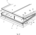
- Insulation by an insulating frame is optional and may be provided along only some of the frame members or as shown surrounding all four frame members 21, 22, 23, 24.
- a roof window such as the roof window 1 shown in Figs 1 and 2 is supplied with a set of mounting brackets 6. As indicated, two mounting brackets 6 are fastened to each side frame member 22, 23. In the following, a single mounting bracket 6 will be described, in association with one side frame member 22. The mounting brackets 6 of the set will most often be identical, although variations are possible.
- the mounting bracket 6 comprises a first bracket leg 61 for fastening to the roof structure and a second bracket leg 62 for fastening to the frame 2 of the roof window 1.
- the second bracket leg 62 comprises engagement means to interact with a corresponding receiving structure in an outer side of the side frame member 22 of the frame 2 of the roof window 1. This ensures that the mounting bracket 6 is positioned correctly on the side frame member 22 and facilitates the installation process.
- the positioning of the mounting bracket 6 may be indicated in both the longitudinal direction and the height direction of the side frame member 22, for instance by suitable markings and/or holes.
- the first bracket leg 61 of the mounting bracket 6 is connected to the second bracket leg 62 via a bend 614.
- the second engagement means 629 is configured to assume an inactive position and an active position, of which the active position is shown.
- the first engagement means 624 is configured to be received in one receiving structure of the outer side of the frame member 22 in the mounted condition of the mounting bracket 6 on the frame 2 of the roof window 1
- the second engagement means 629 is configured to be received in another receiving structure of the outer side of the frame member 22 in the mounted condition of the mounting bracket 6 on the frame 2 of the roof window 1 in its active position only.
- This is shown most clearly in Fig. 4 , in which the first engagement means 624 is received in a first outer groove 27, and the second engagement means 629 is received in a second outer groove 27b.
- At least the side frame members 22, 23 each comprises a plurality of receiving structures at an outer side of the respective side frame member, such that at least one of the receiving structures interacts with the mounting bracket 6 in the mounted condition of the roof window 1.
- the first outer groove 27 and the second outer groove 27b both extend in the longitudinal direction of the side frame member 22 at a distance from each other in the height direction, the first outer groove 27 being located to the exterior of the second outer groove 27b, as seen
- the second section 626 with the second engagement means 629 is connected to the first section 621 via a hinge connection 625, such that the second section 626 is configured to be brought from the inactive position to the active position by rotating the second section 626.
- each of the first and second engagement means comprises a flange 624, 629 protruding at substantially right angles from the respective first and second sections 621, 626.
- Alternative configurations such as discrete spikes are also conceivable.
- the roof window 1 furthermore comprises a hinge assembly 9.
- the hinge assembly 9 is configured in such a way that it allows the sash 3 to be tophung in a first operational condition corresponding to normal use. That is, during normal use the sash 3 is rotated about a substantially horizontal first hinge axis at or near the top frame member 21 and top sash member 31 between a closed position and an open position.
- the hinge assembly 9 comprises a hinge unit 91 with a frame hinge part 92 connected to or connectable to at least the top frame member 21, a sash hinge part 93 connected to at least the top sash member 31, and a hinge pin 94 connecting the frame hinge part 92 with the sash hinge part 93.
- connection to implies that the component in question is in a condition, state or position in which the component in question is in fact connected to a part, whereas “connectable to” is intended to encompass such conditions, states and positions in which the component in question may be connected to the relevant part, but is not necessarily in connection with the part.
- frame hinge part 92 including any sub-components will be described as being connected to parts of the frame 2.
- the top frame coupling plate 96 comprises a base section 961 connected to an inner side of the top frame member 21.
- the top frame coupling plate 96 is connected to the top frame member 21 by means of a plurality of fastening means including at least one spigot 961c on the base section 961 and two bolt elements functioning also as engagement pins 962, 963.
- each engagement pin 962, 963 cooperates with an insert nut 982, 983 on the outer side of the top frame member 21.
- the top frame member 21 comprises a hinge assembly receiving milling 29a and a set of openings 29c, 29e of which openings 29e are through-going openings, or through-holes.
- the side frame coupling plate 97 comprises a base section 971 and is connected to the inner side of the side frame member 22 by means of a plurality of fastening means including at least one spigot 971e on the base section 971 and at least one opening (not shown in detail) for fastening means such as screws 981.
- the side frame member 22 comprises a hinge assembly receiving milling 29b and a set of openings 29d, 29f.
- the pane 4 comprises an exterior sheet 41 and at least one interior sheet, here two interior sheets 42, 43 placed in contact with each other.
- the pane 4 is here a so-called stepped pane in which the exterior sheet 41 comprises an extended portion 41a extending beyond a bottom edge portion 42b of the interior sheets 42, 43 to a bottom edge portion 41b of the exterior sheet 41.
- the pane 4 has a common side edge portion 4b - this applies also to the opposite, not-shown side - and a common top edge portion 4c.
- a spacer 47 is provided between the most exterior interior sheet 42 and the exterior sheet 41 along all edge portions.
- a hinge assembly 9 present in a gap between the top sash member 31 and the top frame member 21, and between the side sash member 32 and the side frame member 22, by which the sash 3 is connected to the frame 2 to provide a tophung hinge connection.
- one such releasable component comprises a cover 24c releasably connected to remaining components of the bottom frame member 24 and defining a cavity relative to the remaining components of the bottom frame member 24.
- the cover 24c may be formed by any suitable material, for instance a profile element of a plastic or metal material.
- the cavity defined by the cover 24c is defined by the inner side of the outer piece 24a in the outwards direction and mainly by the exterior side of the separate inner piece 24b towards the interior.
- edge portions 24c1, 24c2 of the cover 24c are received in receiving grooves in the bottom frame member 24, specifically in one receiving groove 24a1 in the outer piece 24a and one receiving groove 24b1 in the separate inner piece 24b.
- an insulating piece 24d is accommodated in the cavity defined by the cover 24c.
- the cavity defined by the cover 24c is configured to receive an electrical operator (not shown) and the cover 24c is configured to be replaced by a different cover (not shown) allowing operating means of the electrical operator to be connected to the sash 3.
- the roof window 1 in a condition in which the bottom frame member 24 comprises a dummy element configured to be replaced by the socket fitting 51 of the operating assembly 5.
- the roof window 1 were provided in a basic form with a different hinge than the hinge assembly 9 described in the above embodiments, it would also be conceivable to use blind plates to cover the hinge assembly receiving millings 29a, 29b to allow replacement of the previous hinge with the hinge assembly 9.
- a second receiving structure comprises a sealing groove 26 in an exterior side of the inwards protruding portion 21i, 22i, 24i.
- the sealing groove 26 is configured to interact with a frame sealing profile 26p.
- a third receiving structure comprises an first outer groove 27 in an outer side of the frame member 21, 22, 23, 24.
- the first outer groove 27 is configured to interact with a respective piece 71, 72, 73, 74 of the insulating frame 7. The interaction may take place by introducing a longitudinal protrusion 78 of the insulating frame piece into the groove, or to locate separate fastening means correctly.
- each frame member 21, 22, 23, 24 has an inwards facing surface which together form a coherent inwards facing surface. As indicated, this appearance mimics a corresponding coherent inwards facing surface of the sash 3.
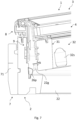
- FIG. 7 Further details visible in the drawings include guiding elements 22g (see Fig. 7 ) and 32g (see Fig. 10 ), which ascertain that the sash 3 is aligned relative to the frame 2 when closing the sash such that any skewness occurring in the open position of the sash 3 is eliminated.
- a screening mounting bracket 32s is visible in Fig. 8 , by which it is possible to install an interior screening device (not shown) in the sash 3 to provide screening of the pane 4.
- An abutment element 22s provides a stop for the bottom sash member 34 during closing.
- a recess 76 is shown which makes place for the mounting bracket 6 to be mounted on the side frame member 23 of the frame 2, and a folding line 77 which allows folding back of part of the side piece 73 of the insulating frame 7 to allow access to the outer side of the side frame member 23.
- At least the side pieces 72, 73 of the insulating frame 7 are provided with such recesses 76 and folding lines 77 at or near the location of the intended positions of the mounting brackets 6 of the set of mounting brackets supplied with the roof window 1.
- the insulating frame 1 may in principle be made from any material with suitable thermal insulating properties. It is presently preferred that a foam material be used, for instance polyethylene foam.
- the reception means comprises two longitudinally extending grooves 32c1, 32c2 at a distance from each other in the height direction, the grooves being open in an outwards direction of the roof window 1.
- the longitudinal profiles forming the intermediate elements 31b, 32b, 33b have a uniform cross-section and may in principle be cut from one and the same profile length. It is preferred that the longitudinal profiles are formed by a continuous moulding process, such as extrusion or pultrusion. Specifically the profiles are formed by pultrusion of a composite material incorporating resin and glass fibre.
- the intermediate element 32b comprises a base portion 32b1 extending substantially in the height direction in the assembled condition of the sash 3 and a head portion 32b2 extending at an angle to the base portion 32b1.
- the base portion 32b1 is provided with the engagement means on a surface facing inwards in the assembled condition, facing an outer surface of the inner element 32c, as shown in Fig. 16 .
- the position, location and length of the individual intermediate elements 31b, 32b and 33b appear also from Figs 3 , 4 , 5 , 10 and 12a .
- the engagement means of the base portion 32b1 of the intermediate element 32b comprises a protruding portion formed as a flange 32b3 extending throughout the length of the profile and configured to engage with a selective one groove 32c1, 32c2 of the inner element 32c of the side sash member 32.
- each intermediate element 32b comprises a stepped section 32b4, which is offset in the inwards direction by an offsetting bend 32b5 relative to the remaining section of the base portion 32b1.
- the engagement means, here the flange 32b3, is provided in the stepped section 32b4.
- the intermediate element 34b comprises a base portion 34b1 extending substantially in the height direction and a head portion 34b2 extending at an angle to the base portion 34b1.
- the base portion 34b1 is provided with the engagement means 34b3 on an inner surface, facing an outer surface of the inner element 34c.
- the engagement means of the base portion 34b1 comprises a protruding portion 34b3 to engage with a selective one groove 34c1, 34c2 of the inner element 34c of the bottom sash member 34.
- Additional fastening means 30y are provided to fasten the intermediate element 34b to the inner element 34c of the bottom sash member 34, in openings 34b6 in stepped section 34b4, which is offset in the inwards direction by offsetting bend 34b5 relative to the remaining section of the base portion 34b1.
- Figs 17 and 18 showing a simplified overview of the main components of the side sash member 32, it is seen how the same components of the sash 3 may accommodate two different thicknesses of the pane 4. This is carried out by changing the position of the engagement means of the intermediate element 32b from the first groove 32c1 to the second groove 32c2. This will require a slightly adapted side frame member 22c. The intermediate elements 31b, 33b, 34b at the other sash members 31, 33, 34 are moved similarly.
- outer edge portion 32b12 of the intermediate element 32b is associated with the head portion 32b2 of the intermediate element 32b via an outer inclined portion 32b11 and a bend 32b10.
- a pane of suitable dimensions is provided, for instance as described in the above.
- the sets of four inner elements and four intermediate elements are provided, for instance as described in the above.
- a set of two corner keys 39 is advantageously provided placed within the longitudinal profile element s 31a, 32a, 33a at the mutually facing mitred ends before placing the pane 4 within the profile element frame structure.
- Sealant 39b is preferably applied to each corner key 39. During assembly, it is ensured that the sealant 39b is able to flow through the primary openings 39a3 of the corner key 39 such that the sealant 39b is distributed.
- Figs 24 to 29a an embodiment is shown in which the roof window 1 is provided with a covering assembly 10.
- the covering assembly 10 generally comprising a flashing assembly and any other auxiliary equipment are described in more detail in Applicant's co-pending patent applications filed on the same date as the present application.
- sealing between the sash 3 and the frame 2 is provided by an exterior sealing plane, an intermediate sealing plane and an interior sealing plane. Reference is also made to the cross-sectional views of the top, side and bottom of the roof window 1 shown and described in the above.
- the interior sealing plane comprises the frame sealing profile 26p provided in the exterior side of each frame member 21, 22, 23, 24 and interacts with the interior side of the respective sash member 31, 32, 33, 34.
- the sash sealing profile 30p1 is provided in sash sealing groove 30g1.
- the intermediate sealing plane comprises the sash sealing profile 30p1 provided in the outer side of each sash member 31, 32, 33, 34 and interacts with the inner side of the respective frame member 21, 22, 23, 24.
- each interface element 81, 82 comprises a base portion 80 with an anchor section 801, an inner leg 86, an outer leg 87, a flange 88 and a sealing portion 89.
- the anchor section 801 of the base portion 80 is received in the interface unit groove 28 in the assembled condition of the roof window 1.
- the sealing portion 89 faces to the exterior and interacts with the top sash member 31 and side sash members 32, 33 during opening and closing of the sash 3 and in the closed position of the sash 3.
- the inner leg 86, the outer leg 87, and the flange 88 form a channel 810, 820 in the top interface element 81 and the side interface element 82.
- a corresponding channel is formed in the other side interface element 83. In this way, water emanating from rain or other precipitation may be guided from the channel 810 in the top interface element 81 to the channels 820 in the side interface elements 82, 83 and further out to the covering assembly 10 (not shown in detail).
- the sealing portion 89 comprises an inner sealing lip 891 and an outer sealing lip 892.
- the inner sealing lip 891 of both the top interface element 81 and of the side interface element 82 is provided sufficiently inwards that the inner sealing lip 891 interacts with the interior of the top sash member 31 and the side sash member 32, cf. Figs 6 and 5 ; however the outer sealing lip 892 of the top interface element 81 is located on the outer side of the top sash member 31. In the embodiment shown, this is due to the fact that the flange 88 of the top interface element 8 is longer than the counterpart flange of the side interface element 82.
- each interface element 81, 82, 83 is formed to be resilient, i.e. as is customary in sealings, the sealing portion 89 is able to be deformed when coming into abutment with another component and then spring back when relaxing, this is not reflected in the figures since they generally show elements in their undeformed condition.
- at least the sealing portion 89 has different properties than at least the base portion 80. This may be provided by co-extrusion or co-moulding of two (or more) different materials.
- the top interface element 81 comprises an additional inner sealing lip 893, a first additional outer sealing lip 894 and a second additional outer sealing lip 895, cf. also Fig. 28 .
- the interface elements 81, 82, 83 furthermore allow interaction with the covering assembly 10 in that the base portion 80, inner leg 86 and flange 88 form a flashing reception groove 85.
- the flashing reception groove 85 has a groove opening 85b and is provided with a number of protrusions 85a.
- the sealing assembly furthermore comprises a pane sealing 30p2. received in pane sealing groove 30g2 It is noted that the pane sealing 30p2 remains stationary relative to the sash 3.
- a clip 22x is mounted on the side element 82 of the interface unit 8.
- the clip 22x is provided with a clip flange 22xa as shown in more detail in Fig. 36 .
- the end plug 38 of the sash side member 32 is in this embodiment provided with an end plug flange 38a. In the closed position of the roof window 1, the end plug flange 38a overlaps the clip flange 22xa.
Landscapes
- Engineering & Computer Science (AREA)
- Civil Engineering (AREA)
- Structural Engineering (AREA)
- Architecture (AREA)
- Physics & Mathematics (AREA)
- Electromagnetism (AREA)
- Wing Frames And Configurations (AREA)
- Vehicle Step Arrangements And Article Storage (AREA)
- Body Structure For Vehicles (AREA)
- Fittings On The Vehicle Exterior For Carrying Loads, And Devices For Holding Or Mounting Articles (AREA)
- Securing Of Glass Panes Or The Like (AREA)
Applications Claiming Priority (3)
| Application Number | Priority Date | Filing Date | Title |
|---|---|---|---|
| DKPA202270160A DK181830B1 (en) | 2022-03-31 | 2022-03-31 | A roof window comprising a frame with an interface unit |
| EP23718975.8A EP4466417B1 (de) | 2022-03-31 | 2023-03-31 | Dachfenster mit einem rahmen mit einer schnittstelleneinheit |
| PCT/DK2023/050077 WO2023186240A1 (en) | 2022-03-31 | 2023-03-31 | A roof window comprising a frame with an interface unit |
Related Parent Applications (1)
| Application Number | Title | Priority Date | Filing Date |
|---|---|---|---|
| EP23718975.8A Division EP4466417B1 (de) | 2022-03-31 | 2023-03-31 | Dachfenster mit einem rahmen mit einer schnittstelleneinheit |
Publications (2)
| Publication Number | Publication Date |
|---|---|
| EP4517023A2 true EP4517023A2 (de) | 2025-03-05 |
| EP4517023A3 EP4517023A3 (de) | 2025-05-14 |
Family
ID=86142708
Family Applications (2)
| Application Number | Title | Priority Date | Filing Date |
|---|---|---|---|
| EP25153071.3A Pending EP4517023A3 (de) | 2022-03-31 | 2023-03-31 | Dachfenster mit einem rahmen mit einer schnittstelleneinheit |
| EP23718975.8A Active EP4466417B1 (de) | 2022-03-31 | 2023-03-31 | Dachfenster mit einem rahmen mit einer schnittstelleneinheit |
Family Applications After (1)
| Application Number | Title | Priority Date | Filing Date |
|---|---|---|---|
| EP23718975.8A Active EP4466417B1 (de) | 2022-03-31 | 2023-03-31 | Dachfenster mit einem rahmen mit einer schnittstelleneinheit |
Country Status (7)
| Country | Link |
|---|---|
| US (1) | US12326037B2 (de) |
| EP (2) | EP4517023A3 (de) |
| CN (1) | CN118974366B (de) |
| DK (1) | DK181830B1 (de) |
| HU (1) | HUE070345T2 (de) |
| PL (1) | PL4466417T3 (de) |
| WO (1) | WO2023186240A1 (de) |
Family Cites Families (20)
| Publication number | Priority date | Publication date | Assignee | Title |
|---|---|---|---|---|
| US4862657A (en) | 1982-01-22 | 1989-09-05 | Wasco Products, Inc. | Ventilating skylight |
| US5044133A (en) | 1988-12-13 | 1991-09-03 | Wasco Products, Inc. | Skylight construction |
| US4928445A (en) * | 1988-12-13 | 1990-05-29 | Wasco Products, Inc. | Skylight construction |
| DE19836175A1 (de) * | 1998-08-10 | 2000-02-17 | Hans Udo Reichstadt | Verriegelungs- und Lüftungssteller für Dachfenster |
| DE10295851T1 (de) * | 2001-01-19 | 2003-12-24 | Vkr Holding As S Diameter Borg | Dachfensterbaueinheit und Einzelteile |
| AU2002952574A0 (en) * | 2002-11-08 | 2002-11-21 | Rodric Lindsay Fooks | Skylight system |
| GB2430943B (en) * | 2005-09-21 | 2010-08-04 | Viridian Concepts Ltd | Roof flashing connections comprising resilient member |
| EP1988230B1 (de) | 2007-05-03 | 2012-08-22 | VKR Holding A/S | Dachfenster |
| NL2002930C2 (en) * | 2009-05-26 | 2010-11-30 | Vaculux B V | WINDOW DEVICE, METHOD FOR MANUFACTURING SUCH A WINDOW DEVICE AND METHOD FOR CONNECTING A TRANSLUCENT ELEMENT TO A FLAT ROOF. |
| WO2018016580A1 (ja) * | 2016-07-20 | 2018-01-25 | 積水化学工業株式会社 | 耐火成形体及び耐火成形体を備えた成形品 |
| GB201620817D0 (en) * | 2016-12-07 | 2017-01-18 | Keylite Roof Windows Ltd | A roof window comprising a cover member |
| DE102017206683A1 (de) * | 2017-04-20 | 2018-10-25 | Roto Frank Ag | Rollladenmontagesatz für ein Dachfenster, Dachfenster mit einem daran montierten Rollladenmontagesatz sowie Verfahren zum Montieren eines Rollladenmontagesatzes an einem Dachfenster |
| US10519709B2 (en) * | 2018-05-21 | 2019-12-31 | Adam Ugliuzza | Flashing retainer assembly |
| US10844651B2 (en) * | 2018-07-26 | 2020-11-24 | Matrex Window System Inc. | Compression gasket for sealing a window in a window frame |
| DK180873B1 (en) | 2018-11-06 | 2022-06-09 | Vkr Holding As | A roof window, and a method of assembling such a roof window |
| US11002016B2 (en) * | 2019-01-10 | 2021-05-11 | Vkr Holding A/S | Connector element for a flashing assembly for use in a roof window arrangement, and a method for weather proofing a roof window arrangement |
| GB2586514B (en) * | 2019-08-23 | 2024-01-03 | The Metal Window Co Ltd | Metal window with thermal shield |
| DK180879B1 (en) | 2019-12-30 | 2022-06-13 | Vkr Holding As | A roof window system with a ventilation unit mounted adjacent to the roof window, and a method of providing ventilation for a building |
| EP3779085B1 (de) * | 2020-02-03 | 2024-01-24 | VKR Holding A/S | Dachfenster |
| DK181327B8 (en) * | 2021-01-12 | 2023-08-15 | Vkr Holding As | A bottom flashing element for a roof penetrating structure, a flashing assembly, and a roof window mounted in an inclined roof |
-
2022
- 2022-03-31 DK DKPA202270160A patent/DK181830B1/en active IP Right Grant
-
2023
- 2023-03-31 WO PCT/DK2023/050077 patent/WO2023186240A1/en not_active Ceased
- 2023-03-31 EP EP25153071.3A patent/EP4517023A3/de active Pending
- 2023-03-31 EP EP23718975.8A patent/EP4466417B1/de active Active
- 2023-03-31 PL PL23718975.8T patent/PL4466417T3/pl unknown
- 2023-03-31 HU HUE23718975A patent/HUE070345T2/hu unknown
- 2023-03-31 CN CN202380031875.5A patent/CN118974366B/zh active Active
- 2023-03-31 US US18/849,046 patent/US12326037B2/en active Active
Also Published As
| Publication number | Publication date |
|---|---|
| WO2023186240A1 (en) | 2023-10-05 |
| HUE070345T2 (hu) | 2025-06-28 |
| EP4466417A1 (de) | 2024-11-27 |
| PL4466417T3 (pl) | 2025-04-28 |
| US20250109629A1 (en) | 2025-04-03 |
| DK202270160A1 (en) | 2023-12-12 |
| EP4517023A3 (de) | 2025-05-14 |
| EP4466417B1 (de) | 2025-01-22 |
| CN118974366A (zh) | 2024-11-15 |
| DK181830B1 (en) | 2025-02-13 |
| US12326037B2 (en) | 2025-06-10 |
| EP4466417C0 (de) | 2025-01-22 |
| CN118974366B (zh) | 2025-07-29 |
Similar Documents
| Publication | Publication Date | Title |
|---|---|---|
| EP4466415B1 (de) | Dachfenster mit einem flügel mit profilelementen und verfahren zur herstellung eines dachfensters | |
| EP4466417B1 (de) | Dachfenster mit einem rahmen mit einer schnittstelleneinheit | |
| EP4253683B1 (de) | Dachfenster mit einer dichtungsanordnung | |
| EP4466416B1 (de) | Dachfenster mit einem rahmen mit aufnahmestrukturen | |
| EP4473172B1 (de) | Dachfenster mit einem flügel mit zwischenelementen | |
| EP4466418B1 (de) | Dachfenster mit lösbaren komponenten | |
| EP4682324A1 (de) | Dachfenster mit einem flügel mit profilelementen und verbesserten witterungsschutzeigenschaften | |
| EP4534787A1 (de) | Dachfenster mit einem scharnier und einer betätigungsanordnung | |
| EP4534773A1 (de) | Dachfenster mit einem rahmen und einem flügel mit profilelementen |
Legal Events
| Date | Code | Title | Description |
|---|---|---|---|
| PUAI | Public reference made under article 153(3) epc to a published international application that has entered the european phase |
Free format text: ORIGINAL CODE: 0009012 |
|
| STAA | Information on the status of an ep patent application or granted ep patent |
Free format text: STATUS: THE APPLICATION HAS BEEN PUBLISHED |
|
| AC | Divisional application: reference to earlier application |
Ref document number: 4466417 Country of ref document: EP Kind code of ref document: P |
|
| AK | Designated contracting states |
Kind code of ref document: A2 Designated state(s): AL AT BE BG CH CY CZ DE DK EE ES FI FR GB GR HR HU IE IS IT LI LT LU LV MC ME MK MT NL NO PL PT RO RS SE SI SK SM TR |
|
| REG | Reference to a national code |
Ref country code: DE Ref legal event code: R079 Free format text: PREVIOUS MAIN CLASS: E04D0013147000 Ipc: E04D0013030000 |
|
| PUAL | Search report despatched |
Free format text: ORIGINAL CODE: 0009013 |
|
| AK | Designated contracting states |
Kind code of ref document: A3 Designated state(s): AL AT BE BG CH CY CZ DE DK EE ES FI FR GB GR HR HU IE IS IT LI LT LU LV MC ME MK MT NL NO PL PT RO RS SE SI SK SM TR |
|
| RIC1 | Information provided on ipc code assigned before grant |
Ipc: E04D 13/147 20060101ALI20250409BHEP Ipc: E04D 13/035 20060101ALI20250409BHEP Ipc: E04D 13/03 20060101AFI20250409BHEP |
|
| STAA | Information on the status of an ep patent application or granted ep patent |
Free format text: STATUS: REQUEST FOR EXAMINATION WAS MADE |
|
| 17P | Request for examination filed |
Effective date: 20250925 |