EP4517023A2 - A roof window comprising a frame with an interface unit - Google Patents
A roof window comprising a frame with an interface unit Download PDFInfo
- Publication number
- EP4517023A2 EP4517023A2 EP25153071.3A EP25153071A EP4517023A2 EP 4517023 A2 EP4517023 A2 EP 4517023A2 EP 25153071 A EP25153071 A EP 25153071A EP 4517023 A2 EP4517023 A2 EP 4517023A2
- Authority
- EP
- European Patent Office
- Prior art keywords
- sash
- roof window
- frame
- interface unit
- interface
- Prior art date
- Legal status (The legal status is an assumption and is not a legal conclusion. Google has not performed a legal analysis and makes no representation as to the accuracy of the status listed.)
- Pending
Links
Images


Classifications
-
- E—FIXED CONSTRUCTIONS
- E06—DOORS, WINDOWS, SHUTTERS, OR ROLLER BLINDS IN GENERAL; LADDERS
- E06B—FIXED OR MOVABLE CLOSURES FOR OPENINGS IN BUILDINGS, VEHICLES, FENCES OR LIKE ENCLOSURES IN GENERAL, e.g. DOORS, WINDOWS, BLINDS, GATES
- E06B7/00—Special arrangements or measures in connection with doors or windows
- E06B7/16—Sealing arrangements on wings or parts co-operating with the wings
- E06B7/22—Sealing arrangements on wings or parts co-operating with the wings by means of elastic edgings, e.g. elastic rubber tubes; by means of resilient edgings, e.g. felt or plush strips, resilient metal strips
- E06B7/23—Plastic, sponge rubber, or like strips or tubes
- E06B7/2305—Plastic, sponge rubber, or like strips or tubes with an integrally formed part for fixing the edging
- E06B7/2312—Plastic, sponge rubber, or like strips or tubes with an integrally formed part for fixing the edging with two or more sealing-lines or -planes between the wing and part co-operating with the wing
-
- E—FIXED CONSTRUCTIONS
- E04—BUILDING
- E04B—GENERAL BUILDING CONSTRUCTIONS; WALLS, e.g. PARTITIONS; ROOFS; FLOORS; CEILINGS; INSULATION OR OTHER PROTECTION OF BUILDINGS
- E04B7/00—Roofs; Roof construction with regard to insulation
- E04B7/18—Special structures in or on roofs, e.g. dormer windows
-
- E—FIXED CONSTRUCTIONS
- E04—BUILDING
- E04D—ROOF COVERINGS; SKY-LIGHTS; GUTTERS; ROOF-WORKING TOOLS
- E04D13/00—Special arrangements or devices in connection with roof coverings; Protection against birds; Roof drainage ; Sky-lights
- E04D13/03—Sky-lights; Domes; Ventilating sky-lights
- E04D13/0305—Supports or connecting means for sky-lights of flat or domed shape
- E04D13/031—Supports or connecting means for sky-lights of flat or domed shape characterised by a frame for connection to an inclined roof
-
- E—FIXED CONSTRUCTIONS
- E04—BUILDING
- E04D—ROOF COVERINGS; SKY-LIGHTS; GUTTERS; ROOF-WORKING TOOLS
- E04D13/00—Special arrangements or devices in connection with roof coverings; Protection against birds; Roof drainage ; Sky-lights
- E04D13/03—Sky-lights; Domes; Ventilating sky-lights
- E04D13/035—Sky-lights; Domes; Ventilating sky-lights characterised by having movable parts
- E04D13/0351—Sky-lights; Domes; Ventilating sky-lights characterised by having movable parts the parts pivoting about a fixed axis
- E04D13/0354—Sky-lights; Domes; Ventilating sky-lights characterised by having movable parts the parts pivoting about a fixed axis the parts being flat
-
- E—FIXED CONSTRUCTIONS
- E04—BUILDING
- E04D—ROOF COVERINGS; SKY-LIGHTS; GUTTERS; ROOF-WORKING TOOLS
- E04D13/00—Special arrangements or devices in connection with roof coverings; Protection against birds; Roof drainage ; Sky-lights
- E04D13/03—Sky-lights; Domes; Ventilating sky-lights
- E04D13/035—Sky-lights; Domes; Ventilating sky-lights characterised by having movable parts
- E04D13/0357—Sky-lights; Domes; Ventilating sky-lights characterised by having movable parts the parts pivoting about an axis supported on a hinged frame or arms
-
- E—FIXED CONSTRUCTIONS
- E04—BUILDING
- E04D—ROOF COVERINGS; SKY-LIGHTS; GUTTERS; ROOF-WORKING TOOLS
- E04D13/00—Special arrangements or devices in connection with roof coverings; Protection against birds; Roof drainage ; Sky-lights
- E04D13/14—Junctions of roof sheathings to chimneys or other parts extending above the roof
- E04D13/147—Junctions of roof sheathings to chimneys or other parts extending above the roof specially adapted for inclined roofs
- E04D13/1473—Junctions of roof sheathings to chimneys or other parts extending above the roof specially adapted for inclined roofs specially adapted to the cross-section of the parts extending above the roof
- E04D13/1475—Junctions of roof sheathings to chimneys or other parts extending above the roof specially adapted for inclined roofs specially adapted to the cross-section of the parts extending above the roof wherein the parts extending above the roof have a generally rectangular cross-section
-
- E—FIXED CONSTRUCTIONS
- E06—DOORS, WINDOWS, SHUTTERS, OR ROLLER BLINDS IN GENERAL; LADDERS
- E06B—FIXED OR MOVABLE CLOSURES FOR OPENINGS IN BUILDINGS, VEHICLES, FENCES OR LIKE ENCLOSURES IN GENERAL, e.g. DOORS, WINDOWS, BLINDS, GATES
- E06B1/00—Border constructions of openings in walls, floors, or ceilings; Frames to be rigidly mounted in such openings
- E06B1/70—Sills; Thresholds
- E06B1/702—Window sills
Definitions
- the present invention relates to a roof window comprising a frame, a sash, and a pane, in which the frame comprises a set of frame members including a top frame member, two side frame members and a bottom frame member and the sash comprises a set of sash members including a top sash member, two side sash members and a bottom sash member.
- Roof windows to be installed in inclined roof surfaces come in a variety of types.
- parameters such as operability, thermal properties, weather-tightness, and suitable finishing to the interior of the building are typically given substantial weight; however, it is also often desired and in some areas in fact necessary to factor in the external appearance as well.
- This applies in particular when installing roof windows in conservation areas, in which building regulations may demand that the roof windows meet standard or local requirements.
- certain requirements apply depending on whether the installation concerns a newly fitted roof window, or to replace an existing window or rooflight as part of a renovation or refurbishment project.
- the windows or rooflights of past times were typically made of cast iron with single glass pane pieces, separated by one or more cast iron glazing bars, and the thermal efficiency of these roof windows or rooflights left room for improvement.
- conservation roof windows are typically provided with an insulating pane, while at the same time setting out to mimic the look of traditional rooflights.
- the conservation roof window is able to be installed with a "low profile", i.e. that the height of the parts of the roof window protruding above the surrounding roofing is as small as possible. This is particularly pronounced in buildings with substantially flat roofing materials, such as slate or shingle. To meet this requirement, most major roof window manufacturers allow installation in at least two levels, thus accommodating the height of various roofing profiles and installation conditions.
- a roof window of the kind mentioned in the introduction which is furthermore characterised in that an interface unit is provided to interact with auxiliary equipment and/or other components of the roof window in an assembled condition of the frame.
- a single interface unit ensures that suitable interaction with auxiliary equipment such as sealing profiles and coverings is made possible in a simple way. Manufacture, assembly and installation may be carried out securely. Other components that are eligible for interaction with the interface unit include the sash. This is particularly relevant in cases where the interface unit has a sealing function.
- the interface unit comprises a top interface element and two side interface elements configured to be received in a receiving structure comprising an interface unit groove in an exterior side of the top frame member and two side members.
- a receiving structure comprising an interface unit groove in an exterior side of the top frame member and two side members.
- each interface element comprises a base portion with an anchor section, said anchor section being configured to be received in the interface unit groove in the exterior side of the top frame member and two side members.
- the interface unit forms part of an exterior sealing plane relative to the sash.
- the exterior sealing plane provides a first shield against weather including rain and other precipitation, wind, sound etc.
- the intermediate and interior sealing planes provide additional security.
- the exterior sealing plane is provided by the interface element at the top frame and sash members and side frame and sash members. In this way, vital weather-proofing is obtained at the location where the sash and frame adjoin in the closed position of the sash.
- Each interface element preferably comprises an inner leg and an outer leg, which inner leg and outer leg extend towards the exterior from a base portion, a flange and a sealing portion. In this way, each interface element is provided with a certain extent in the height and width directions, thus facilitating the interaction with other elements.
- the inner leg, the outer leg, and the flange form a channel in the top interface element and the side interface elements.
- the interface unit provides a guiding canal for water emanating from rain and other precipitation.
- the sealing portion comprises an inner sealing lip and an outer sealing lip.
- Each interface element may be provided as a two-component element, wherein at least the sealing portion has different properties than at least the base portion. Since the base portion has as its primary function to ensure reliable connection to the frame of the roof window, the base portion will typically need to possess stiffer material properties than the sealing portion which needs to be elastic and flexible.
- a stabilising plate may be placed in a channel of the top element of the interface unit.
- an extension plate may be fastened to the profile element of the top sash member to protrude into a channel of the top element of the interface unit. This ensures proper guidance of water into the channel of the interface unit even in roof windows built into roofs with a large inclination.
- Insulation by an insulating frame is optional and may be provided along only some of the frame members or as shown surrounding all four frame members 21, 22, 23, 24.
- a roof window such as the roof window 1 shown in Figs 1 and 2 is supplied with a set of mounting brackets 6. As indicated, two mounting brackets 6 are fastened to each side frame member 22, 23. In the following, a single mounting bracket 6 will be described, in association with one side frame member 22. The mounting brackets 6 of the set will most often be identical, although variations are possible.
- the mounting bracket 6 comprises a first bracket leg 61 for fastening to the roof structure and a second bracket leg 62 for fastening to the frame 2 of the roof window 1.
- the second bracket leg 62 comprises engagement means to interact with a corresponding receiving structure in an outer side of the side frame member 22 of the frame 2 of the roof window 1. This ensures that the mounting bracket 6 is positioned correctly on the side frame member 22 and facilitates the installation process.
- the positioning of the mounting bracket 6 may be indicated in both the longitudinal direction and the height direction of the side frame member 22, for instance by suitable markings and/or holes.
- the first bracket leg 61 of the mounting bracket 6 is connected to the second bracket leg 62 via a bend 614.
- the second engagement means 629 is configured to assume an inactive position and an active position, of which the active position is shown.
- the first engagement means 624 is configured to be received in one receiving structure of the outer side of the frame member 22 in the mounted condition of the mounting bracket 6 on the frame 2 of the roof window 1
- the second engagement means 629 is configured to be received in another receiving structure of the outer side of the frame member 22 in the mounted condition of the mounting bracket 6 on the frame 2 of the roof window 1 in its active position only.
- This is shown most clearly in Fig. 4 , in which the first engagement means 624 is received in a first outer groove 27, and the second engagement means 629 is received in a second outer groove 27b.
- At least the side frame members 22, 23 each comprises a plurality of receiving structures at an outer side of the respective side frame member, such that at least one of the receiving structures interacts with the mounting bracket 6 in the mounted condition of the roof window 1.
- the first outer groove 27 and the second outer groove 27b both extend in the longitudinal direction of the side frame member 22 at a distance from each other in the height direction, the first outer groove 27 being located to the exterior of the second outer groove 27b, as seen
- the second section 626 with the second engagement means 629 is connected to the first section 621 via a hinge connection 625, such that the second section 626 is configured to be brought from the inactive position to the active position by rotating the second section 626.
- each of the first and second engagement means comprises a flange 624, 629 protruding at substantially right angles from the respective first and second sections 621, 626.
- Alternative configurations such as discrete spikes are also conceivable.
- the roof window 1 furthermore comprises a hinge assembly 9.
- the hinge assembly 9 is configured in such a way that it allows the sash 3 to be tophung in a first operational condition corresponding to normal use. That is, during normal use the sash 3 is rotated about a substantially horizontal first hinge axis at or near the top frame member 21 and top sash member 31 between a closed position and an open position.
- the hinge assembly 9 comprises a hinge unit 91 with a frame hinge part 92 connected to or connectable to at least the top frame member 21, a sash hinge part 93 connected to at least the top sash member 31, and a hinge pin 94 connecting the frame hinge part 92 with the sash hinge part 93.
- connection to implies that the component in question is in a condition, state or position in which the component in question is in fact connected to a part, whereas “connectable to” is intended to encompass such conditions, states and positions in which the component in question may be connected to the relevant part, but is not necessarily in connection with the part.
- frame hinge part 92 including any sub-components will be described as being connected to parts of the frame 2.
- the top frame coupling plate 96 comprises a base section 961 connected to an inner side of the top frame member 21.
- the top frame coupling plate 96 is connected to the top frame member 21 by means of a plurality of fastening means including at least one spigot 961c on the base section 961 and two bolt elements functioning also as engagement pins 962, 963.
- each engagement pin 962, 963 cooperates with an insert nut 982, 983 on the outer side of the top frame member 21.
- the top frame member 21 comprises a hinge assembly receiving milling 29a and a set of openings 29c, 29e of which openings 29e are through-going openings, or through-holes.
- the side frame coupling plate 97 comprises a base section 971 and is connected to the inner side of the side frame member 22 by means of a plurality of fastening means including at least one spigot 971e on the base section 971 and at least one opening (not shown in detail) for fastening means such as screws 981.
- the side frame member 22 comprises a hinge assembly receiving milling 29b and a set of openings 29d, 29f.
- the pane 4 comprises an exterior sheet 41 and at least one interior sheet, here two interior sheets 42, 43 placed in contact with each other.
- the pane 4 is here a so-called stepped pane in which the exterior sheet 41 comprises an extended portion 41a extending beyond a bottom edge portion 42b of the interior sheets 42, 43 to a bottom edge portion 41b of the exterior sheet 41.
- the pane 4 has a common side edge portion 4b - this applies also to the opposite, not-shown side - and a common top edge portion 4c.
- a spacer 47 is provided between the most exterior interior sheet 42 and the exterior sheet 41 along all edge portions.
- a hinge assembly 9 present in a gap between the top sash member 31 and the top frame member 21, and between the side sash member 32 and the side frame member 22, by which the sash 3 is connected to the frame 2 to provide a tophung hinge connection.
- one such releasable component comprises a cover 24c releasably connected to remaining components of the bottom frame member 24 and defining a cavity relative to the remaining components of the bottom frame member 24.
- the cover 24c may be formed by any suitable material, for instance a profile element of a plastic or metal material.
- the cavity defined by the cover 24c is defined by the inner side of the outer piece 24a in the outwards direction and mainly by the exterior side of the separate inner piece 24b towards the interior.
- edge portions 24c1, 24c2 of the cover 24c are received in receiving grooves in the bottom frame member 24, specifically in one receiving groove 24a1 in the outer piece 24a and one receiving groove 24b1 in the separate inner piece 24b.
- an insulating piece 24d is accommodated in the cavity defined by the cover 24c.
- the cavity defined by the cover 24c is configured to receive an electrical operator (not shown) and the cover 24c is configured to be replaced by a different cover (not shown) allowing operating means of the electrical operator to be connected to the sash 3.
- the roof window 1 in a condition in which the bottom frame member 24 comprises a dummy element configured to be replaced by the socket fitting 51 of the operating assembly 5.
- the roof window 1 were provided in a basic form with a different hinge than the hinge assembly 9 described in the above embodiments, it would also be conceivable to use blind plates to cover the hinge assembly receiving millings 29a, 29b to allow replacement of the previous hinge with the hinge assembly 9.
- a second receiving structure comprises a sealing groove 26 in an exterior side of the inwards protruding portion 21i, 22i, 24i.
- the sealing groove 26 is configured to interact with a frame sealing profile 26p.
- a third receiving structure comprises an first outer groove 27 in an outer side of the frame member 21, 22, 23, 24.
- the first outer groove 27 is configured to interact with a respective piece 71, 72, 73, 74 of the insulating frame 7. The interaction may take place by introducing a longitudinal protrusion 78 of the insulating frame piece into the groove, or to locate separate fastening means correctly.
- each frame member 21, 22, 23, 24 has an inwards facing surface which together form a coherent inwards facing surface. As indicated, this appearance mimics a corresponding coherent inwards facing surface of the sash 3.
- FIG. 7 Further details visible in the drawings include guiding elements 22g (see Fig. 7 ) and 32g (see Fig. 10 ), which ascertain that the sash 3 is aligned relative to the frame 2 when closing the sash such that any skewness occurring in the open position of the sash 3 is eliminated.
- a screening mounting bracket 32s is visible in Fig. 8 , by which it is possible to install an interior screening device (not shown) in the sash 3 to provide screening of the pane 4.
- An abutment element 22s provides a stop for the bottom sash member 34 during closing.
- a recess 76 is shown which makes place for the mounting bracket 6 to be mounted on the side frame member 23 of the frame 2, and a folding line 77 which allows folding back of part of the side piece 73 of the insulating frame 7 to allow access to the outer side of the side frame member 23.
- At least the side pieces 72, 73 of the insulating frame 7 are provided with such recesses 76 and folding lines 77 at or near the location of the intended positions of the mounting brackets 6 of the set of mounting brackets supplied with the roof window 1.
- the insulating frame 1 may in principle be made from any material with suitable thermal insulating properties. It is presently preferred that a foam material be used, for instance polyethylene foam.
- the reception means comprises two longitudinally extending grooves 32c1, 32c2 at a distance from each other in the height direction, the grooves being open in an outwards direction of the roof window 1.
- the longitudinal profiles forming the intermediate elements 31b, 32b, 33b have a uniform cross-section and may in principle be cut from one and the same profile length. It is preferred that the longitudinal profiles are formed by a continuous moulding process, such as extrusion or pultrusion. Specifically the profiles are formed by pultrusion of a composite material incorporating resin and glass fibre.
- the intermediate element 32b comprises a base portion 32b1 extending substantially in the height direction in the assembled condition of the sash 3 and a head portion 32b2 extending at an angle to the base portion 32b1.
- the base portion 32b1 is provided with the engagement means on a surface facing inwards in the assembled condition, facing an outer surface of the inner element 32c, as shown in Fig. 16 .
- the position, location and length of the individual intermediate elements 31b, 32b and 33b appear also from Figs 3 , 4 , 5 , 10 and 12a .
- the engagement means of the base portion 32b1 of the intermediate element 32b comprises a protruding portion formed as a flange 32b3 extending throughout the length of the profile and configured to engage with a selective one groove 32c1, 32c2 of the inner element 32c of the side sash member 32.
- each intermediate element 32b comprises a stepped section 32b4, which is offset in the inwards direction by an offsetting bend 32b5 relative to the remaining section of the base portion 32b1.
- the engagement means, here the flange 32b3, is provided in the stepped section 32b4.
- the intermediate element 34b comprises a base portion 34b1 extending substantially in the height direction and a head portion 34b2 extending at an angle to the base portion 34b1.
- the base portion 34b1 is provided with the engagement means 34b3 on an inner surface, facing an outer surface of the inner element 34c.
- the engagement means of the base portion 34b1 comprises a protruding portion 34b3 to engage with a selective one groove 34c1, 34c2 of the inner element 34c of the bottom sash member 34.
- Additional fastening means 30y are provided to fasten the intermediate element 34b to the inner element 34c of the bottom sash member 34, in openings 34b6 in stepped section 34b4, which is offset in the inwards direction by offsetting bend 34b5 relative to the remaining section of the base portion 34b1.
- Figs 17 and 18 showing a simplified overview of the main components of the side sash member 32, it is seen how the same components of the sash 3 may accommodate two different thicknesses of the pane 4. This is carried out by changing the position of the engagement means of the intermediate element 32b from the first groove 32c1 to the second groove 32c2. This will require a slightly adapted side frame member 22c. The intermediate elements 31b, 33b, 34b at the other sash members 31, 33, 34 are moved similarly.
- outer edge portion 32b12 of the intermediate element 32b is associated with the head portion 32b2 of the intermediate element 32b via an outer inclined portion 32b11 and a bend 32b10.
- a pane of suitable dimensions is provided, for instance as described in the above.
- the sets of four inner elements and four intermediate elements are provided, for instance as described in the above.
- a set of two corner keys 39 is advantageously provided placed within the longitudinal profile element s 31a, 32a, 33a at the mutually facing mitred ends before placing the pane 4 within the profile element frame structure.
- Sealant 39b is preferably applied to each corner key 39. During assembly, it is ensured that the sealant 39b is able to flow through the primary openings 39a3 of the corner key 39 such that the sealant 39b is distributed.
- Figs 24 to 29a an embodiment is shown in which the roof window 1 is provided with a covering assembly 10.
- the covering assembly 10 generally comprising a flashing assembly and any other auxiliary equipment are described in more detail in Applicant's co-pending patent applications filed on the same date as the present application.
- sealing between the sash 3 and the frame 2 is provided by an exterior sealing plane, an intermediate sealing plane and an interior sealing plane. Reference is also made to the cross-sectional views of the top, side and bottom of the roof window 1 shown and described in the above.
- the interior sealing plane comprises the frame sealing profile 26p provided in the exterior side of each frame member 21, 22, 23, 24 and interacts with the interior side of the respective sash member 31, 32, 33, 34.
- the sash sealing profile 30p1 is provided in sash sealing groove 30g1.
- the intermediate sealing plane comprises the sash sealing profile 30p1 provided in the outer side of each sash member 31, 32, 33, 34 and interacts with the inner side of the respective frame member 21, 22, 23, 24.
- each interface element 81, 82 comprises a base portion 80 with an anchor section 801, an inner leg 86, an outer leg 87, a flange 88 and a sealing portion 89.
- the anchor section 801 of the base portion 80 is received in the interface unit groove 28 in the assembled condition of the roof window 1.
- the sealing portion 89 faces to the exterior and interacts with the top sash member 31 and side sash members 32, 33 during opening and closing of the sash 3 and in the closed position of the sash 3.
- the inner leg 86, the outer leg 87, and the flange 88 form a channel 810, 820 in the top interface element 81 and the side interface element 82.
- a corresponding channel is formed in the other side interface element 83. In this way, water emanating from rain or other precipitation may be guided from the channel 810 in the top interface element 81 to the channels 820 in the side interface elements 82, 83 and further out to the covering assembly 10 (not shown in detail).
- the sealing portion 89 comprises an inner sealing lip 891 and an outer sealing lip 892.
- the inner sealing lip 891 of both the top interface element 81 and of the side interface element 82 is provided sufficiently inwards that the inner sealing lip 891 interacts with the interior of the top sash member 31 and the side sash member 32, cf. Figs 6 and 5 ; however the outer sealing lip 892 of the top interface element 81 is located on the outer side of the top sash member 31. In the embodiment shown, this is due to the fact that the flange 88 of the top interface element 8 is longer than the counterpart flange of the side interface element 82.
- each interface element 81, 82, 83 is formed to be resilient, i.e. as is customary in sealings, the sealing portion 89 is able to be deformed when coming into abutment with another component and then spring back when relaxing, this is not reflected in the figures since they generally show elements in their undeformed condition.
- at least the sealing portion 89 has different properties than at least the base portion 80. This may be provided by co-extrusion or co-moulding of two (or more) different materials.
- the top interface element 81 comprises an additional inner sealing lip 893, a first additional outer sealing lip 894 and a second additional outer sealing lip 895, cf. also Fig. 28 .
- the interface elements 81, 82, 83 furthermore allow interaction with the covering assembly 10 in that the base portion 80, inner leg 86 and flange 88 form a flashing reception groove 85.
- the flashing reception groove 85 has a groove opening 85b and is provided with a number of protrusions 85a.
- the sealing assembly furthermore comprises a pane sealing 30p2. received in pane sealing groove 30g2 It is noted that the pane sealing 30p2 remains stationary relative to the sash 3.
- a clip 22x is mounted on the side element 82 of the interface unit 8.
- the clip 22x is provided with a clip flange 22xa as shown in more detail in Fig. 36 .
- the end plug 38 of the sash side member 32 is in this embodiment provided with an end plug flange 38a. In the closed position of the roof window 1, the end plug flange 38a overlaps the clip flange 22xa.
Landscapes
- Engineering & Computer Science (AREA)
- Civil Engineering (AREA)
- Structural Engineering (AREA)
- Architecture (AREA)
- Physics & Mathematics (AREA)
- Electromagnetism (AREA)
- Wing Frames And Configurations (AREA)
- Vehicle Step Arrangements And Article Storage (AREA)
- Body Structure For Vehicles (AREA)
- Fittings On The Vehicle Exterior For Carrying Loads, And Devices For Holding Or Mounting Articles (AREA)
- Securing Of Glass Panes Or The Like (AREA)
Abstract
Description
- The present invention relates to a roof window comprising a frame, a sash, and a pane, in which the frame comprises a set of frame members including a top frame member, two side frame members and a bottom frame member and the sash comprises a set of sash members including a top sash member, two side sash members and a bottom sash member.
- Roof windows to be installed in inclined roof surfaces come in a variety of types. When selecting a roof window type for a specific installation location in a building, parameters such as operability, thermal properties, weather-tightness, and suitable finishing to the interior of the building are typically given substantial weight; however, it is also often desired and in some areas in fact necessary to factor in the external appearance as well. This applies in particular when installing roof windows in conservation areas, in which building regulations may demand that the roof windows meet standard or local requirements. Thus, certain requirements apply depending on whether the installation concerns a newly fitted roof window, or to replace an existing window or rooflight as part of a renovation or refurbishment project.
- The windows or rooflights of past times were typically made of cast iron with single glass pane pieces, separated by one or more cast iron glazing bars, and the thermal efficiency of these roof windows or rooflights left room for improvement. To fulfil the energy performance required by modern day building regulations, conservation roof windows are typically provided with an insulating pane, while at the same time setting out to mimic the look of traditional rooflights.
- In many installation situations it is a further requirement that the conservation roof window is able to be installed with a "low profile", i.e. that the height of the parts of the roof window protruding above the surrounding roofing is as small as possible. This is particularly pronounced in buildings with substantially flat roofing materials, such as slate or shingle. To meet this requirement, most major roof window manufacturers allow installation in at least two levels, thus accommodating the height of various roofing profiles and installation conditions.
- With an ever-increasing awareness of environmental considerations and the wish to reduce or even eliminate the climate footprint of products, there is furthermore a need for providing products which are more environmentally friendly in terms of manufacturing, supply, installation, and use.
- Taking all of the above requirements into account, it is an ongoing quest to improve a roof window for conservation purposes.
- With this background, it is an object of the invention to provide a roof window by which the manufacturing, assembly and installation process is rendered more flexible while at the same time, the roof window provides for adequate protection against the weather when in use.
- This and further objects are achieved with a roof window of the kind mentioned in the introduction which is furthermore characterised in that an interface unit is provided to interact with auxiliary equipment and/or other components of the roof window in an assembled condition of the frame.
- The provision of a single interface unit ensures that suitable interaction with auxiliary equipment such as sealing profiles and coverings is made possible in a simple way. Manufacture, assembly and installation may be carried out securely. Other components that are eligible for interaction with the interface unit include the sash. This is particularly relevant in cases where the interface unit has a sealing function.
- In a presently preferred embodiment, the interface unit comprises a top interface element and two side interface elements configured to be received in a receiving structure comprising an interface unit groove in an exterior side of the top frame member and two side members. In this way, it is possible to easily fasten the interface elements to the frame and thereby obtain central functionalities towards the sash and for instance a surrounding covering assembly. The interface elements thus provide a coherent structure along the top and the sides in the form of a football goal.
- In a further development of this preferred embodiment, each interface element comprises a base portion with an anchor section, said anchor section being configured to be received in the interface unit groove in the exterior side of the top frame member and two side members. By dividing the interface unit into different functional sections including a base portion, it is possible to confer different properties to different sections. For instance, fastening the interface elements will require different properties and it thus possible to tailor the properties of the anchor section such that appropriate retention is achieved.
- In a presently preferred embodiment, the interface unit forms part of an exterior sealing plane relative to the sash. By this design, additional protection against the weather is provided in that the exterior sealing plane provides a first shield against weather including rain and other precipitation, wind, sound etc. To protect the unavoidable gap between the frame and the sash, the intermediate and interior sealing planes provide additional security.
- Preferably, the exterior sealing plane is provided by the interface element at the top frame and sash members and side frame and sash members. In this way, vital weather-proofing is obtained at the location where the sash and frame adjoin in the closed position of the sash.
- Each interface element preferably comprises an inner leg and an outer leg, which inner leg and outer leg extend towards the exterior from a base portion, a flange and a sealing portion. In this way, each interface element is provided with a certain extent in the height and width directions, thus facilitating the interaction with other elements.
- In a preferred further development, the inner leg, the outer leg, and the flange form a channel in the top interface element and the side interface elements. In this way, the interface unit provides a guiding canal for water emanating from rain and other precipitation.
- To improve the sealing properties even further, the sealing portion comprises an inner sealing lip and an outer sealing lip.
- Preferably, the top interface element comprises an additional inner sealing lip, a first additional outer sealing lip and a second additional outer sealing lip. This has proven to improve the sealing properties even further.
- To improve the versatility of the interface unit, the base portion, the inner leg and the flange form a flashing reception groove in one embodiment. This makes it possible to provide interaction of the roof window with a covering assembly and thus provide a weather-proof transition to the surrounding roofing in a simple and efficient manner.
- Each interface element may be provided as a two-component element, wherein at least the sealing portion has different properties than at least the base portion. Since the base portion has as its primary function to ensure reliable connection to the frame of the roof window, the base portion will typically need to possess stiffer material properties than the sealing portion which needs to be elastic and flexible.
- In order to improve the structural integrity and ensuing proper functioning of the interface unit at the top of the roof window, a stabilising plate may be placed in a channel of the top element of the interface unit.
- While the configuration of the sash members including a profile element by itself entails appropriate guidance of water onto the surrounding, an extension plate may be fastened to the profile element of the top sash member to protrude into a channel of the top element of the interface unit. This ensures proper guidance of water into the channel of the interface unit even in roof windows built into roofs with a large inclination.
- Improved retention of the interface unit may be achieved by a clip mounted on the side element of the interface unit, the clip being provided with a clip flange to interact with an end plug flange of an end plug of the sash side member so as to allow the end plug flange to overlap the clip flange in the closed position of the roof window.
- Other presently preferred embodiments and further advantages will be apparent from the subsequent detailed description and drawings.
- A feature described in relation to one of the aspects may also be incorporated in the other aspect, and the advantage of the feature is applicable to all aspects in which it is incorporated.
- In the following description embodiments of the invention will be described with reference to the drawings, in which
-
Fig. 1 is a perspective view of a roof window in an embodiment of the invention, seen from an interior side; -
Fig. 2 is a perspective view of the roof window ofFig. 1 , seen from an exterior side; -
Fig. 3 is a perspective cross-sectional view of a side of a roof window in another embodiment, with a mounting bracket, corresponding to a cross-section along the line III-III inFig. 2 ; -
Fig. 4 is a view corresponding toFig. 3 , with an insulating frame piece shown exploded; -
Fig. 5 is a cross-sectional view along the line III-III inFig. 2 ; -
Fig. 6 is a cross-sectional view of a roof window in a further embodiment, corresponding to a cross-section along the line VI-VI inFig. 2 ; -
Fig. 7 is a view corresponding toFig. 6 , with the sash in an open position; -
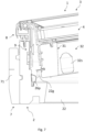
Fig. 8 is a perspective cross-sectional view of a roof window in an embodiment incorporating an operating assembly, corresponding to a cross-section along the line VIII-VIII inFig. 2 ; -
Fig. 9 is a cross-sectional view along a line parallel to the line VIII-VIII inFig. 2 ; -
Fig. 10 is a partial perspective view of a roof window incorporating a hinge assembly and an operating assembly, with the sash in an open position; -
Fig. 11 is a partial perspective sectional view of the frame of the roof window ofFig. 10 , together with an insulating frame; -
Fig. 12a is a partial perspective view of the sash of the roof window ofFig. 10 ; -
Fig. 12b is a perspective sectional view of the sash ofFig. 12a ; -
Fig. 13a is an exploded sectional view of the details ofFig. 12a ; -
Fig. 13b is a perspective view of a detail of the sash ofFig. 12a ; -
Fig. 14a is a partially exploded perspective view of the sash ofFig. 12a ; -
Fig. 14b is a perspective sectional view of details shown inFig. 13a ; -
Fig. 15 is a partial perspective view of an intermediate element of the sash of the roof window ofFig. 10 ; -
Fig. 16 is a sectional view corresponding toFig. 5 , but of the sash isolated from the frame; -
Fig. 17 is a simplified cross-sectional view corresponding toFig. 16 ; -
Fig. 18 is a view corresponding toFig. 17 , of a roof window in another embodiment of the invention, in which the pane has a larger total thickness; -
Fig. 19 is an exploded perspective view of an upper corner of the sash of a roof window in a further embodiment; -
Figs 20 and 21 are perspective views, seen from different angles, of a corner key of the sash ofFig. 19 ; -
Fig. 22 is an exploded perspective view of a sash and a frame of a roof window in an embodiment incorporating a hinge assembly; -
Fig. 23 is a partial perspective view of details of the roof window ofFig. 22 ; -
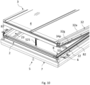
Fig. 24 is a perspective view of a roof window in an embodiment of the invention, incorporating a flashing assembly; -
Fig. 25 is a partial perspective exploded view of an upper corner of the frame of the roof window in the embodiment ofFig. 24 ; -
Figs 26 and 27 are cross-sectional views of elements of the interface unit ofFig. 25 ; -
Fig. 28 is a partial side view of a roof window in the open position shown inFig. 7 , showing the interaction between the sash and the interface unit ofFig. 25 ; and -
Fig. 29a is a cross-sectional view along the line XXIX-XXIX inFig. 24 ; -
Fig. 29b is a view corresponding toFig. 29a , of an alternative embodiment of the general embodiment ofFig. 24 ; -
Fig. 30 is a cross-sectional view of an alternative embodiment, corresponding to a cross-sectional view along the line XXX-XXX of the general embodiment ofFig. 24 ; -
Fig. 31 is a cross-sectional view of an alternative embodiment, corresponding to a cross-sectional view along the line XXXI-XXXI of the general embodiment ofFig. 24 ; -
Fig. 32 is a partial perspective view of the top right-hand corner of the alternative embodiment of the roof window; -
Fig. 33 is a partial sectional view of the top right-hand corner of an embodiment of the roof window according to the invention; -
Fig. 34 is a partial perspective view of the bottom right-hand corner of the alternative embodiment of the roof window; -
Fig. 35 is a perspective view, on a larger scale, of a detail of the embodiment ofFig. 34 ; and -
Fig. 36 is a perspective view, on a larger scale, of a further detail of the embodiment ofFig. 34 . - In the following detailed description, a preferred embodiment of the present invention will be described. However, it is to be understood that features of the different embodiments are exchangeable between the embodiments and may be combined in different ways, unless anything else is specifically indicated. It may also be noted that, for the sake of clarity, the dimensions of certain components illustrated in the drawings may differ from the corresponding dimensions in real-life implementations.
- It is noted that terms such as "up", "down", "left-hand", "right-hand", "exterior", "interior", "outer", "inner" are relative and refers to the viewpoint in question. In general, when referred to an exterior side, this relates to a side of a roof window in the mounted condition facing the outdoors or external side of the building. Conversely, an interior side refers to a side facing the internal side of the building, i.e. typically a subjacent room including any light shaft. Terms such as "outwards" and "inwards" are directions generally perpendicular to an interior-exterior direction, taking as its base point a centre of the roof window.
- Referring initially to
Figs 1 and2 , aroof window 1 is shown. Theroof window 1 is intended to be installed in an inclined roof surface (not shown). - The
roof window 1 comprises aframe 2, asash 3, and apane 4. Theframe 2 comprises a set of frame members including atop frame member 21, twoside frame members bottom frame member 24. Correspondingly, thesash 3 comprises a set of sash members including atop sash member 31, twoside sash members bottom sash member 34. While theframe 2 andsash 3 are described as rectangular structures, some principles of the presented concepts may be applicable to other geometrical shapes as well. - The
pane 4 comprises a number of edge portions generally associated to members of thesash 3 as will be described in further detail below. When in a closed position, anexterior pane surface 4e defines a plane of theroof window 1 in an assembled condition of theroof window 1. The assembled condition of theroof window 1 is achieved when main components of theframe 2 andsash 3 have been assembled and theframe 2 andsash 3 are connected to each other, for instance in an installed position when theroof window 1 is ready for use. Correspondingly, an assembled condition of thesash 3 is achieved once main components of thesash 3 have been assembled, and an assembled condition of theframe 2 when main components of theframe 2 are assembled. - An
interior pane surface 4i faces the interior, typically a room of a building subjacent the roof surface in which theroof window 1 is installed. Aglazing bar 45 is fitted to theexterior pane surface 4e, and aglazing bar cover 46 is fitted on theinterior pane surface 4i. Although less practical, it would also be possible to have a two-part pane with two pane halves divided by a throughgoing glazing bar. In wide roof windows, it is also possible to have more than one glazing bar, for instance two glazing bars dividing the surface of the pane visible from the exterior into three sections. - In the embodiments shown, the
sash 3 is openable relative to theframe 2, to obtain one or more open positions. In such open positions, thesash 3 andpane 4 are moved out of the plane of theroof window 1. As will be described in the following, thesash 3 is shown as being tophung, i.e. during normal use, thesash 3 is rotated about a substantially horizontal hinge axis at or near thetop frame member 21 andtop sash member 31. It is however conceivable to apply some principles of the presented concepts for roof windows on different types of windows having other opening patterns, or being provided as fixed skylights. - Further details shown in
Figs 1 and2 include anoperating assembly 5, here shown as a manual handwinder or screwjack. Other operating assemblies may be present as well. - Also shown is a
representative mounting bracket 6 forming part of a plurality of mounting brackets forming a load-transferring connection between theroof window 1 and a surrounding roof structure (not shown). Such a roof structure may include rafters and battens, plywood or other construction materials. - Finally, an insulating
frame 7 is shown. Insulation by an insulating frame is optional and may be provided along only some of the frame members or as shown surrounding all fourframe members - In the following description of various embodiments, elements having the same or analogous function carry the same reference numerals throughout. Suitable variations and modifications will be apparent to the person skilled in the art.
- Typically, a roof window such as the
roof window 1 shown inFigs 1 and2 is supplied with a set of mountingbrackets 6. As indicated, two mountingbrackets 6 are fastened to eachside frame member single mounting bracket 6 will be described, in association with oneside frame member 22. The mountingbrackets 6 of the set will most often be identical, although variations are possible. - The mounting
bracket 6 comprises afirst bracket leg 61 for fastening to the roof structure and asecond bracket leg 62 for fastening to theframe 2 of theroof window 1. To that end, thesecond bracket leg 62 comprises engagement means to interact with a corresponding receiving structure in an outer side of theside frame member 22 of theframe 2 of theroof window 1. This ensures that the mountingbracket 6 is positioned correctly on theside frame member 22 and facilitates the installation process. The positioning of the mountingbracket 6 may be indicated in both the longitudinal direction and the height direction of theside frame member 22, for instance by suitable markings and/or holes. Thefirst bracket leg 61 of the mountingbracket 6 is connected to thesecond bracket leg 62 via abend 614. - In the embodiment shown, the
second bracket leg 62 is provided with a first engagement means 624 in afirst section 621 of thesecond bracket leg 62 and a second engagement means 629 in asecond section 626 of thesecond bracket leg 62. - Of these two engagement means 624, 629, the second engagement means 629 is configured to assume an inactive position and an active position, of which the active position is shown.
- The first engagement means 624 is configured to be received in one receiving structure of the outer side of the
frame member 22 in the mounted condition of the mountingbracket 6 on theframe 2 of theroof window 1, and the second engagement means 629 is configured to be received in another receiving structure of the outer side of theframe member 22 in the mounted condition of the mountingbracket 6 on theframe 2 of theroof window 1 in its active position only. This is shown most clearly inFig. 4 , in which the first engagement means 624 is received in a firstouter groove 27, and the second engagement means 629 is received in a secondouter groove 27b. At least theside frame members bracket 6 in the mounted condition of theroof window 1. The firstouter groove 27 and the secondouter groove 27b both extend in the longitudinal direction of theside frame member 22 at a distance from each other in the height direction, the firstouter groove 27 being located to the exterior of the secondouter groove 27b, as seen in the height direction. - To bring the
second section 626 with the second engagement means 629 from the position in an aperture 620 in thesecond bracket leg 62 to a position in which thesecond section 626 is located substantially in extension of thefirst section 621, thesecond section 626 with the second engagement means 629 is connected to thefirst section 621 via ahinge connection 625, such that thesecond section 626 is configured to be brought from the inactive position to the active position by rotating thesecond section 626. - In the embodiment shown, each of the first and second engagement means comprises a
flange second sections - Referring first to
Figs 6 and7 it is shown that theroof window 1 furthermore comprises ahinge assembly 9. - The
hinge assembly 9 is configured in such a way that it allows thesash 3 to be tophung in a first operational condition corresponding to normal use. That is, during normal use thesash 3 is rotated about a substantially horizontal first hinge axis at or near thetop frame member 21 andtop sash member 31 between a closed position and an open position. - Referring now also to
Figs 22 and23 , it is seen that thehinge assembly 9 comprises ahinge unit 91 with aframe hinge part 92 connected to or connectable to at least thetop frame member 21, asash hinge part 93 connected to at least thetop sash member 31, and ahinge pin 94 connecting theframe hinge part 92 with thesash hinge part 93. - The term "connected to" implies that the component in question is in a condition, state or position in which the component in question is in fact connected to a part, whereas "connectable to" is intended to encompass such conditions, states and positions in which the component in question may be connected to the relevant part, but is not necessarily in connection with the part. In the description of
Figs 22 and23 , theframe hinge part 92 including any sub-components will be described as being connected to parts of theframe 2. - In the following, a
coupling unit 95 of thehinge assembly 9 will be described in some detail. Details of thehinge assembly 9 are described in more detail in Applicant's co-pending patent applications filed on the same date as the present application. - The
coupling unit 95 is configured to allow selective coupling of at least theframe hinge part 92 of thehinge unit 91 to thetop frame member 21 and optionally to one of theside frame members coupling unit 95 will be described as comprising both a topframe coupling plate 96 and a sideframe coupling plate 97. Alternative configurations are conceivable. - The top
frame coupling plate 96 comprises abase section 961 connected to an inner side of thetop frame member 21. The topframe coupling plate 96 is connected to thetop frame member 21 by means of a plurality of fastening means including at least onespigot 961c on thebase section 961 and two bolt elements functioning also as engagement pins 962, 963. In this case, eachengagement pin insert nut top frame member 21. To accommodate the topframe coupling plate 96, thetop frame member 21 comprises a hingeassembly receiving milling 29a and a set ofopenings 29c, 29e of which openings 29e are through-going openings, or through-holes. - The side
frame coupling plate 97 comprises abase section 971 and is connected to the inner side of theside frame member 22 by means of a plurality of fastening means including at least onespigot 971e on thebase section 971 and at least one opening (not shown in detail) for fastening means such as screws 981. To receive the sideframe coupling plate 97, theside frame member 22 comprises a hingeassembly receiving milling 29b and a set ofopenings - During normal use, i.e. when the
roof window 1 has been installed, and a user wishes to put thesash 3 in a ventilating position, the opening, closing and parking may be carried out by the assistance of an operating assembly, for instance as the shown manual handwinder or screwjack constituting the operatingassembly 5. - Referring first to
Fig. 8 , the operatingassembly 5 comprises a sash fitting 55, aspindle part 52 with aspindle 521 connected to a socket fitting 51 via anut part 53, and ahandle 522, the sash fitting 55 being connected to thebottom sash member 34 and the socket fitting 51 being connected to thebottom frame member 24 in a mounted condition of the operating assembly such that upon rotation of thespindle part 52 relative to thenut part 53, thebottom sash member 34 is moved relative to thebottom frame member 24. - In the embodiment shown, the
roof window 1 may be provided in a supply condition which is suitable for packaging and transportation, the sash fitting 55 is connected to thebottom sash member 34 of theroof window 1 whereas thespindle part 52 with thenut part 53 and the socket fitting 51 are provided separately from theroof window 1. - The
nut part 53 comprises a nut ring 531 connected to a set offlanges 512 protruding from abase plate 511 of the socket fitting 51, here by means of a set ofbolts 532.Holes 513 are provided in thebase plate 511 for mounting thesocket part 51 to thebottom frame member 24. - The operating
assembly 5 furthermore comprises asplit 56 associated to the sash fitting 55, thesplit 56 being displaceable between an active position in which it is in engagement with a set ofopenings 553 in a set offlanges 552 protruding from abase plate 551 of the sash fitting 55 and an inactive position to reveal a reception gap between theflanges 552 of thesash fitting 55. - The
spindle part 52 comprises anend portion 54 configured to cooperate with the sash fitting 55 in the mounted condition. - As shown in the cross-sectional view of the bottom part of the
roof window 1 inFigs 8 and9 , thepane 4 comprises anexterior sheet 41 and at least one interior sheet, here twointerior sheets pane 4 is here a so-called stepped pane in which theexterior sheet 41 comprises anextended portion 41a extending beyond abottom edge portion 42b of theinterior sheets bottom edge portion 41b of theexterior sheet 41. Referring now also toFigs 4 and5 , showing side and top parts of theroof window 1, respectively, thepane 4 has a commonside edge portion 4b - this applies also to the opposite, not-shown side - and a commontop edge portion 4c. Aspacer 47 is provided between the most exteriorinterior sheet 42 and theexterior sheet 41 along all edge portions. - Common to all
sash members sash 3 according to the invention is that each sash member comprises aprofile element inner element intermediate element side sash member 33 not shown in cross-section has a similar configuration as the shownside sash member 32. - The
intermediate element respective sash member profile element inner element sash member intermediate elements sash members side sash members sash 3 will be designed with equal properties though. - Referring also to
Fig. 12a , theintermediate elements top sash member 31 and the twoside sash members intermediate element 34b of thebottom sash member 34 comprises a set of separate fittings described in greater detail in connection withFigs 14a-b . Details of the respectiveintermediate elements - The
inner elements sash members pane 4. That is, edge portions of thepane 4 partly overlap theinner elements top edge portion 4c, theside edge portion 4b, and the opposite side edge portion, and thebottom edge portion 42b of theinterior sheet 42 are all located on the outer side of the coherent sash structure provided by the inner elements such that anyspacers 47 and other elements present along the edge portions of thepane 4 are hidden from view by theinner elements inner elements sash members - As will also be described in further detail in connection with the embodiment below, the
profile elements sash members pane 4, and theintermediate element sash member inner element - Also indicated in
Figs 5 and6 is ahinge assembly 9 present in a gap between thetop sash member 31 and thetop frame member 21, and between theside sash member 32 and theside frame member 22, by which thesash 3 is connected to theframe 2 to provide a tophung hinge connection. - Regarding the
frame 2 of theroof window 1, eachframe member frame 2. - In the embodiment shown, the
top frame member 21 and the twoside frame members - Referring particularly to
Figs 8 and9 , thebottom frame member 24 comprises anouter piece 24a and a separateinner piece 24b. Theouter piece 24a and the separateinner piece 24b may be formed by the same material as thetop frame member 21 and theside frame members - A further feature of the
roof window 1 in the shown embodiment is that theframe 2 comprises at least one releasable component configured to allow replacement with a different set of components to change the functionality of theroof window 1. - In the embodiment shown, one such releasable component comprises a
cover 24c releasably connected to remaining components of thebottom frame member 24 and defining a cavity relative to the remaining components of thebottom frame member 24. Thecover 24c may be formed by any suitable material, for instance a profile element of a plastic or metal material. - Here, where the
bottom frame member 24 comprises theouter piece 24a and the separateinner piece 24b, the cavity defined by thecover 24c is defined by the inner side of theouter piece 24a in the outwards direction and mainly by the exterior side of the separateinner piece 24b towards the interior. - To obtain the releasable connection, edge portions 24c1, 24c2 of the
cover 24c are received in receiving grooves in thebottom frame member 24, specifically in one receiving groove 24a1 in theouter piece 24a and one receiving groove 24b1 in the separateinner piece 24b. - In the embodiment shown, in which the
roof window 1 is prepared for manual operation by means of the operatingassembly 5, an insulatingpiece 24d is accommodated in the cavity defined by thecover 24c. - In order to change the functionality of the
roof window 1, the cavity defined by thecover 24c is configured to receive an electrical operator (not shown) and thecover 24c is configured to be replaced by a different cover (not shown) allowing operating means of the electrical operator to be connected to thesash 3. - It is also conceivable to allow the sash fitting 55 connected to the
bottom sash member 34 to be selectively connected to such an electrical operator in which case the sash fitting 55 is simply reused for the operating means of the electrical operator. - Likewise, it is conceivable to provide the
roof window 1 in a condition in which thebottom frame member 24 comprises a dummy element configured to be replaced by the socket fitting 51 of the operatingassembly 5. - Correspondingly, if the
roof window 1 were provided in a basic form with a different hinge than thehinge assembly 9 described in the above embodiments, it would also be conceivable to use blind plates to cover the hingeassembly receiving millings hinge assembly 9. - A first receiving structure comprises a lining
groove 25 in an interior side of eachframe member groove 25 is configured to interact with a set of interior lining panels. Such lining panels typically form the transition between theroof window 1 and in interior wall. In thebottom frame member 24, afirst groove portion 25a is provided in theouter piece 24a and asecond groove portion 25b in the separateinner piece 24b. In the assembled condition of theframe 2, the first andsecond groove portions groove 25. - In the embodiment shown, each
frame member portion corresponding sash member sash 3 move towards the exterior when opening thesash 3 relative to theframe 2. - A second receiving structure comprises a sealing
groove 26 in an exterior side of the inwards protrudingportion groove 26 is configured to interact with aframe sealing profile 26p. - A third receiving structure comprises an first
outer groove 27 in an outer side of theframe member outer groove 27 is configured to interact with arespective piece frame 7. The interaction may take place by introducing alongitudinal protrusion 78 of the insulating frame piece into the groove, or to locate separate fastening means correctly. - Taking again the perspective as seen from a user from the interior of the building, in the roof of which the
roof window 1 is installed, it is also noted that the inwards protrudingportion frame member sash 3. - A fourth receiving structure comprises an
interface unit groove 28 in an exterior side of thetop frame member 21 and twoside frame members interface unit groove 28 interacts with a respective top andside element interface unit 8, the function of which will be described further below. - Further details visible in the drawings include guiding
elements 22g (seeFig. 7 ) and 32g (seeFig. 10 ), which ascertain that thesash 3 is aligned relative to theframe 2 when closing the sash such that any skewness occurring in the open position of thesash 3 is eliminated. Ascreening mounting bracket 32s is visible inFig. 8 , by which it is possible to install an interior screening device (not shown) in thesash 3 to provide screening of thepane 4. Anabutment element 22s provides a stop for thebottom sash member 34 during closing. - Details of the insulating
frame 7 are also shown in these figures; as mentioned in the above, theinsulation frame 7 includestop piece 71,side pieces bottom piece 74. In the embodiments shown, each such insulation frame piece comprisesprotrusion 78 to be received in the outer side of the respective frame member, and anindentation 75 to interact with auxiliary equipment in the form of an underroof collar described in more detail in Applicant's co-pending patent applications filed on the same date as the present application. With particular reference toFig. 11 , arecess 76 is shown which makes place for the mountingbracket 6 to be mounted on theside frame member 23 of theframe 2, and afolding line 77 which allows folding back of part of theside piece 73 of the insulatingframe 7 to allow access to the outer side of theside frame member 23. At least theside pieces frame 7 are provided withsuch recesses 76 andfolding lines 77 at or near the location of the intended positions of the mountingbrackets 6 of the set of mounting brackets supplied with theroof window 1. The insulatingframe 1 may in principle be made from any material with suitable thermal insulating properties. It is presently preferred that a foam material be used, for instance polyethylene foam. - Turning now to the description of the connection between the elements of the
sash 3, the engagement between theintermediate elements top sash member 31 and the twoside sash members inner element - With particular reference to
Fig. 16 , an outer side of each inner element, here as shown theinner element 32c of theside sash member 32, is provided with reception means configured to receive the engagement means of theintermediate element 32b of theside sash member 32. - In the embodiment shown, the reception means comprises two longitudinally extending grooves 32c1, 32c2 at a distance from each other in the height direction, the grooves being open in an outwards direction of the
roof window 1. - In the embodiment shown, the longitudinal profiles forming the
intermediate elements - Thus, only one of these intermediate elements will be described in detail, namely
intermediate element 32b. Referring now toFig. 15 , theintermediate element 32b comprises a base portion 32b1 extending substantially in the height direction in the assembled condition of thesash 3 and a head portion 32b2 extending at an angle to the base portion 32b1. The base portion 32b1 is provided with the engagement means on a surface facing inwards in the assembled condition, facing an outer surface of theinner element 32c, as shown inFig. 16 . The position, location and length of the individualintermediate elements Figs 3 ,4 ,5 ,10 and12a . - In the embodiment shown, the engagement means of the base portion 32b1 of the
intermediate element 32b comprises a protruding portion formed as a flange 32b3 extending throughout the length of the profile and configured to engage with a selective one groove 32c1, 32c2 of theinner element 32c of theside sash member 32. - The base portion 32b1 of each
intermediate element 32b comprises a stepped section 32b4, which is offset in the inwards direction by an offsetting bend 32b5 relative to the remaining section of the base portion 32b1. The engagement means, here the flange 32b3, is provided in the stepped section 32b4. - Additional fastening means 30x (cf.
Fig. 12a and16 ) are provided to fasten the intermediate element orelements 32b to theinner element 32c of theside sash member 32. In order to receive the additional fastening means 30x, the base portion 32b1 of theintermediate element 32b comprises openings 32b6 configured to receive the additional fastening means 30x, namely in the stepped section 32b4. - Turning now in particular to
Figs 14a and 14b , the connection between theintermediate element 34b and theinner element 34c of thebottom sash member 34 will be described in detail. - Just as the
intermediate elements intermediate element 34b comprises a base portion 34b1 extending substantially in the height direction and a head portion 34b2 extending at an angle to the base portion 34b1. The base portion 34b1 is provided with the engagement means 34b3 on an inner surface, facing an outer surface of theinner element 34c. The engagement means of the base portion 34b1 comprises a protruding portion 34b3 to engage with a selective one groove 34c1, 34c2 of theinner element 34c of thebottom sash member 34. Additional fastening means 30y are provided to fasten theintermediate element 34b to theinner element 34c of thebottom sash member 34, in openings 34b6 in stepped section 34b4, which is offset in the inwards direction by offsetting bend 34b5 relative to the remaining section of the base portion 34b1. - In the embodiment shown, the
intermediate element 34b of thebottom sash member 34 comprises a set of fittings. Two such sets may be provided along the length of thebottom sash member 34. - Each set of fittings comprises a connecting fitting provided with the engagement means configured to form a structural connection with the
inner element 34c in one of at least two distinct positions in the height direction. The connecting fitting comprises a first fitting part 34b0 and a second fitting part 34b10. The first fitting part 34b0 comprises the engagement means and the second fitting part 34b10 is configured to be connected to the first fitting part 34b0 to function as a spacer between the outer surface of theinner element 34c of thebottom sash member 34 and the first fitting part 34b0. To connect the first and second fitting parts 34b0, 34b10 with each other, the second fitting part 34b10 is provided with at least one resilient hook 34b11 configured to interact with a corresponding opening 34b12 in the first fitting part 34b0. The head portion 34b2 of theintermediate element 34b of thebottom sash member 34 is received in a slit 34a5 of an inner portion 34a2 of theprofile element 34a of thebottom sash member 34 in the assembled condition of thesash 3. - Turning now to
Figs 17 and 18 , showing a simplified overview of the main components of theside sash member 32, it is seen how the same components of thesash 3 may accommodate two different thicknesses of thepane 4. This is carried out by changing the position of the engagement means of theintermediate element 32b from the first groove 32c1 to the second groove 32c2. This will require a slightly adaptedside frame member 22c. Theintermediate elements other sash members - Focus will now be on the profile elements of the
sash 3. The general configuration of theprofile elements side sash members Figs 3 to 6 and10 while details are shown in the cross-sectional view ofFig. 16 . Theprofile element 34a of thebottom sash member 34 is shown most clearly inFigs 12a to 14b . - Corresponding to the above, only the
profile element 32a of theside sash member 32 will be described in representation of the longitudinal profiles of thetop sash member 31 and the twoside sash members - The details common to all
profile elements
Eachprofile element - The head portion 32a1, 34a1 is substantially parallel to the plane of the
roof window 1 in the assembled condition of theroof window 1, and the adjoining outer portion 32a3, 34a3 is substantially perpendicular to the head portion 32a1, 34a1. - However, the head portion 32a1 of the
profile element 32a of each of the top andside sash members exterior pane surface 4e, and on the outer side of theside edge portion 4b and thetop edge portion 4c of thepane 4, whereas the head portion 34a1 of theprofile element 34a of thebottom sash member 34 is located on the interior side of theextended portion 41a of theexterior sheet 41 of thepane 4. - The
profile element 32a of theside sash member 32 and theprofile element 34a of thebottom sash member 34 are thus separated by a layer of glass; nevertheless, an overlap is provided by selecting a length of theprofile elements side sash members top edge portion 4c of thepane 4 and thebottom edge portion 41b of theexterior sheet 41 of thepane 4. The length of theprofile element 34a of thebottom sash member 34 is suitably selected to extend substantially to theside edge portion 4b of thepane 4. - The length of the
profile element 31a of thetop sash member 31 is chosen in accordance with the dimensions of thepane 4 and the desired manner of joining theprofile element 31a to theprofile elements profile element 31a of thetop sash member 31 and therespective profile element side sash members sash 3, seeFig. 19 . - Also visible in
Figs 12a to 13b are anend plug 38 which closes off theprofile element 32a of theside sash member 32. The end plug 38 is provided with friction-increasing ribs and a snap arm, not described in detail. Theglazing bar 45 is provided with a counterpart end plug. Furthermore, a trailingelement 37 is provided to drain any condensed water out to a profile element sealing 34p. - To ensure a tight joint at the mitred joints, a
corner key 39 is provided at each mitred joint, seeFigs 19-21 . During manufacture, asealant 39b is suitably applied as will be described in further detail below with particular reference toFigs 19 to 21 . - The
corner key 39 has a generally L-shaped configuration with two perpendicular legs 39a1 divided by a channel 39a2. In the channel 39a2, a set of primary openings 39a3 is provided. - Furthermore, each leg 39a1 is adjoined by a depending skirt 39a4 on a first side. Here, a secondary opening 39a5 is provided.
- In order to fit the profile of the
profile elements - As shown in
Figs 20 and 21 , the channel 39a2 ends in a tongue 39a7, optionally adjoining an inclined channel section 39a8. - The
profile elements pane 4 in an upside-down position, i.e. with the respective head portions 32a1 facing a substrate such as an assembly table. This step of the assembly of thesash 3 may take place after theintermediate elements respective profile elements Figs 16 and19 , arepane clips 4t, which are placed at suitable distances from each other along thetop edge portion 4c andside edge portions 4b of thepane 4. In the embodiment shown, the interaction between the main components of thesash 3 is defined by the following configuration of the components:
Each of the longitudinal profiles forming theprofile elements top sash member 31 and the twoside sash members pane 4 in the assembled condition of thesash 3. - The head portion 32a1 of each
profile element pane 4e in the assembled condition of thesash 3. - The inner portion 32a2 is inclined from the head portion 32a1 relative to the head portion 32a1 and extends inwards and to the interior, towards the exterior surface of the
pane 4e in the assembled condition of thesash 3. - The inner portion 32a2 is adjoined by a first bend 32a4 configured to be located at or near the exterior surface of the
pane 4e. - A second bend 32a5 is provided as shown in for example
Fig. 16 . The second bend 32a5 has as its function to accommodate asealing 4p relative to the exterior surface of thepane 4e. - A third bend 32a6 is also provided, said third bend 32a6 being configured to accommodate an inner edge portion 32b9 of the
intermediate element 32b relative to an interior side of the inner portion 32a2. For a detailed overview of theintermediate element 32b, conferFig. 15 . - A transition portion 32a7 is provided between the head portion 32a1 and the inner portion 32a2. The transition portion 32a7 is configured to accommodate a ridge portion 32b7 of the
intermediate element 32b. - A fourth bend 32a8 is provided adjacent the outer portion 32a3 of the
profile element 32a. The fourth bend 32a8 is configured to accommodate an outer edge portion 32b12 of theintermediate element 32b. - The inner portion 32a2 of the
profile element 32a is configured to be located opposite an inner inclined portion 32b8 of theintermediate element 32b in the assembled condition of thesash 3. - Finally, the outer edge portion 32b12 of the
intermediate element 32b is associated with the head portion 32b2 of theintermediate element 32b via an outer inclined portion 32b11 and a bend 32b10. - All in all, the configuration of the described embodiment makes it possible to provide a secure engagement between the
intermediate elements profile elements - The length of the
intermediate elements side sash members profile elements - At the
bottom sash member 34, the head portion 34a1 of theprofile element 34a is provided with at least one longitudinally extending groove 34a4 to receive arespective sealing strip 4s. These sealingstrips 4s may be formed by silicone to form an adhesive connection between theprofile element 34a and theextended portion 41a of theexterior sheet 41 of thepane 4. A masking 44 may be provided at theextended portion 41a on in interior side of theexterior sheet 41. - As described in the above, the
intermediate element sash member inner element intermediate element 34b of thebottom sash member 34 also to theprofile element 34a, the head portion 34b2 of theintermediate element 34b is configured to be received in a slit 34a5 of an inner portion 34a2 of theprofile element 34a of thebottom sash member 34 in the assembled condition of thesash 3, seeFigs 14a-b . To increase the strength of the inner portion 34a2, this portion may be formed as a double-layer, folded portion. - The manufacture of the
sash 3 may in principle take place in any suitable manner. In the following, one presently preferred method will be described: - In a first step, a set of three longitudinal profiles is provided. The longitudinal profiles may for instance be formed a single profile length of an extruded material such as metal, for instance aluminium. Other materials and manufacturing processes are conceivable, including roll forming of steel or other metal, or of a composite material.
- Secondly, mitre shapes are formed at mutually facing ends of the longitudinal profiles. If the longitudinal profiles are formed from a single length, and if convenient, the mitre shapes may be formed in a coherent length by aptly formed incisions to form inner corners at the intersection between the top and the sides.
- A pane of suitable dimensions is provided, for instance as described in the above.
- The sets of four inner elements and four intermediate elements are provided, for instance as described in the above.
- The longitudinal profiles are now placed in an upside-down position on an assembly table to form a profile element frame structure constituting three sides of a rectangle. This typically takes place by guiding elements fixable to the assembly table corresponding to the outer circumference of the sash.
- The pane is placed within the profile element frame structure, and the profile element structure is connected to the inner elements, optionally via the intermediate elements, to form the sash. During this procedure, the intermediate elements at the top and sides are typically inserted into the counterpart profile elements. The inner elements may as describedabove be connected to each other to form an inner element frame structure, which is placed on the pane, following which the intermediate elements are connected to the respective inner elements.
- Referring briefly back to
Figs 19 to 21 , a set of twocorner keys 39 is advantageously provided placed within the longitudinal profile element s 31a, 32a, 33a at the mutually facing mitred ends before placing thepane 4 within the profile element frame structure.Sealant 39b is preferably applied to eachcorner key 39. During assembly, it is ensured that thesealant 39b is able to flow through the primary openings 39a3 of thecorner key 39 such that thesealant 39b is distributed. - In the embodiment shown, each
corner key 39 is configured to be mechanically connected to the respectiveadjacent profile elements - In embodiments in which the
roof window 1 comprises one or more glazing bars, such asglazing bar 45, the glazing bar or bars is/are aligned on the assembly table before placing thepane 4 within the profile element frame structure. Theglazing bar 45 is provided with one or moreadhesive strips 45a to fasten to theexterior surface 4e of thepane 4. - Referring now in particular to
Figs 24 to 29a , an embodiment is shown in which theroof window 1 is provided with a coveringassembly 10. Details of the coveringassembly 10 generally comprising a flashing assembly and any other auxiliary equipment are described in more detail in Applicant's co-pending patent applications filed on the same date as the present application. - In the following, a sealing assembly of the
roof window 1 will be described. Some details of the sealing assembly have been described in the above as well. - The sealing assembly generally comprises a set of sealing profiles.
- In the embodiment shown, sealing between the
sash 3 and theframe 2 is provided by an exterior sealing plane, an intermediate sealing plane and an interior sealing plane. Reference is also made to the cross-sectional views of the top, side and bottom of theroof window 1 shown and described in the above. - The interior sealing plane comprises the
frame sealing profile 26p provided in the exterior side of eachframe member respective sash member - At the bottom side, the intermediate sealing plane comprises the sash sealing profile 30p1 provided in the outer side of each
sash member respective frame member - The exterior sealing plane is provided in that the profile element sealing 34p on the
profile element 34a of thebottom sash member 34 is in contact with the outer side of thebottom frame member 34 in the closed position of thesash 3. - At the top and sides, the exterior sealing plane is defined by the
interface elements Figs 26 and 27 , the similarities and differences between thetop interface element 81 and the side interface elements, here represented byinterface element 82, in the embodiment shown will be described:
Eachinterface element base portion 80 with ananchor section 801, aninner leg 86, anouter leg 87, aflange 88 and a sealingportion 89. Theanchor section 801 of thebase portion 80 is received in theinterface unit groove 28 in the assembled condition of theroof window 1. The sealingportion 89 faces to the exterior and interacts with thetop sash member 31 andside sash members sash 3 and in the closed position of thesash 3. - Together, the
inner leg 86, theouter leg 87, and theflange 88 form achannel top interface element 81 and theside interface element 82. A corresponding channel is formed in the otherside interface element 83. In this way, water emanating from rain or other precipitation may be guided from thechannel 810 in thetop interface element 81 to thechannels 820 in theside interface elements - Common to both the
top interface element 81 and theside interface element 82 in the embodiment shown is that the sealingportion 89 comprises aninner sealing lip 891 and anouter sealing lip 892. Theinner sealing lip 891 of both thetop interface element 81 and of theside interface element 82 is provided sufficiently inwards that theinner sealing lip 891 interacts with the interior of thetop sash member 31 and theside sash member 32, cf.Figs 6 and5 ; however theouter sealing lip 892 of thetop interface element 81 is located on the outer side of thetop sash member 31. In the embodiment shown, this is due to the fact that theflange 88 of thetop interface element 8 is longer than the counterpart flange of theside interface element 82. It is noted that while at least the sealingportion 89 of eachinterface element portion 89 is able to be deformed when coming into abutment with another component and then spring back when relaxing, this is not reflected in the figures since they generally show elements in their undeformed condition. In general, at least the sealingportion 89 has different properties than at least thebase portion 80. This may be provided by co-extrusion or co-moulding of two (or more) different materials. - To ensure a tight interaction at the top of the
roof window 1, thetop interface element 81 comprises an additionalinner sealing lip 893, a first additionalouter sealing lip 894 and a second additionalouter sealing lip 895, cf. alsoFig. 28 . - In the embodiment shown, the
interface elements assembly 10 in that thebase portion 80,inner leg 86 andflange 88 form aflashing reception groove 85. Theflashing reception groove 85 has agroove opening 85b and is provided with a number ofprotrusions 85a. - The sealing assembly furthermore comprises a pane sealing 30p2. received in pane sealing groove 30g2 It is noted that the pane sealing 30p2 remains stationary relative to the
sash 3. - Referring now to
Figs 29b to 36 , details of alternative embodiments will be described. Only differences relative to the above-mentioned embodiment will be described in detail. - In
Fig. 29b , afoam element 32f is shown present in thesash side member 32. A similar foam element may be present in the oppositesash side member 33 as well. The longitudinal extension of thefoam element 32f may be such that thefoam element 32f extends over a major part of the length of thesash side member 32. Thefoam element 32f abuts the interior side of the head portion 32b2 of theintermediate element 32b along the extent of theintermediate element 32b, and is allowed to expand towards the interior side of the head portion 32a1 of theprofile element 32a of theside sash member 32 in the portions of thefoam element 32f protruding beyond the longitudinal ends of theintermediate element 32b. Thefoam element 32f has general climate shielding properties. - In
Fig. 30 , a stabilisingplate 310x is placed in thechannel 810 of thetop element 81 of theinterface unit 8 to improve the structural properties. Furthermore, anextension plate 310y is shown fastened to theprofile element 31a of thetop sash member 31 to protrude into thechannel 810. Theextension plate 310y improves guidance of precipitation into thechannel 810 and for further guidance towards the sides of the roof window. This is particularly relevant in roof windows built into roofs of a large inclination. The relative positions of the stabilisingplate 310x and theextension plate 310y are shown more clearly inFig. 32 . For ease of reading of the relevant portions of theinterface unit 8,Fig. 33 shows thetop element 81 of theinterface unit 8 without the stabilisingplate 310x and without thesash 3 including theextension plate 310y. -
Fig. 31 shows the interaction between the bottom of theroof window 1 and the coveringassembly 10. - Finally,
Fig. 34 show a view of the lower right-hand corner of theroof window 1, in which thesash 3 has been lifted slightly relative to theframe 2 for clarity reasons. - Here, a
clip 22x is mounted on theside element 82 of theinterface unit 8. Theclip 22x is provided with a clip flange 22xa as shown in more detail inFig. 36 . The end plug 38 of thesash side member 32 is in this embodiment provided with anend plug flange 38a. In the closed position of theroof window 1, theend plug flange 38a overlaps the clip flange 22xa. - In general, components of the roof window are easily disassembled and each component may in principle be reused, be recycled by appropriate environmentally responsible disposal means, or the material be recovered for other uses.
-
- 1. A roof window (1) comprising a frame (2), a sash (3), and a pane (4), in which
- the frame (2) comprises a set of frame members including a top frame member (21), two side frame members (22, 23) and a bottom frame member (24) and the sash (3) comprises a set of sash members including a top sash member (31), two side sash members (32, 33) and a bottom sash member (34),
- characterised in that
- an interface unit (8) is provided to interact with auxiliary equipment and/or other components of the roof window (1) in an assembled condition of the frame (2).
- 2. A roof window according to
embodiment 1, wherein the interface unit (8) comprises a top interface element (81) and two side interface elements (82, 83) configured to be received in a receiving structure comprising an interface unit groove (28) in an exterior side of the top frame member (21) and two side members (22, 23). - 3. A roof window according to
embodiment 2, wherein each interface element (81, 82, 83) comprises a base portion (80) with an anchor section (801), said anchor section (801) being configured to be received in the interface unit groove (28) in the exterior side of the top frame member (21) and two side members (22, 23). - 4. A roof window according to any one of the preceding embodiments, wherein the interface unit (8) forms part of an exterior sealing plane relative to the sash (3).
- 5. A roof window according to
embodiment 4, wherein the exterior sealing plane is provided by the interface element (81, 82, 83) at the top frame and sash members (21, 31) and side frame and sash members (22, 23, 32, 33). - 6. A roof window according to
embodiment 5, wherein each interface element (81, 82, 83) comprises an inner leg (86) and an outer leg (87), which inner leg (86) and outer leg (87) extend towards the exterior from a base portion (80), a flange (88) and a sealing portion (89). - 7. A roof window according to
embodiment 6, wherein the inner leg (86), the outer leg (87), and the flange (88) form a channel (810, 820) in the top interface element (81) and the side interface elements (82, 83). - 8. A roof window according to any one of
embodiments - 9. A roof window according to
embodiment 8, wherein the top interface element (81) comprises an additional inner sealing lip (893), a first additional outer sealing lip (894) and a second additional outer sealing lip (895). - 10. A roof window according to any one of
embodiments 6 to 9, wherein the base portion (80), the inner leg (86) and the flange (88) form a flashing reception groove (85), the flashing reception groove (85) being preferably provided with a series of protrusions (85a) protruding from the base portion (80) and from the flange (88). - 11. A roof window according to any one of the preceding embodiments, wherein each interface element (81,82, 83) is provided as a two-component element, wherein at least the sealing portion (89) has different properties than at least the base portion (80).
- 12. A roof window according to any one of
embodiments 7 to 11, wherein a stabilising plate (310x) is placed in a channel (810) of the top element (81) of the interface unit (8). - 13. A roof window (1) according to any one of
embodiments 7 to 12, wherein an extension plate (310y) is fastened to the profile element (31a) of the top sash member (31) to protrude into a channel (810) of the top element (81) of the interface unit (8). - 14. A roof window according to any one of the preceding embodiments, wherein a clip (22x) is mounted on the side element (82) of the interface unit (8), and wherein the clip (22x) is provided with a clip flange (22xa) to interact with an end plug flange (38a) of an end plug (38) of the sash side member (32) so as to allow the end plug flange (38a) to overlap the clip flange (22xa) in the closed position of the roof window (1).
-
- 1 roof window
- 2 frame
- 21 top frame member
- 21i inwards protruding portion
- 22 side frame member
- 22c adapted side frame member
- 22i inwards protruding portion
- 22s abutment element
- 22x clip
- 22xa clip flange
- 23 side frame member
- 24 bottom frame member
- 24a outer piece of bottom frame member
- 24a1 receiving groove
- 24b separate inner piece of bottom frame member
- 24b1 receiving groove
- 24c cover
- 24c1 edge portion
- 24c2 edge portion
- 24d insulating piece
- 24i inwards protruding portion
- 25 lining groove
- 25a first groove portion
- 25b second groove portion
- 26 sealing groove
- 26p frame sealing profile
- 27 first outer groove
- 27b second outer groove
- 28 interface unit groove
- 29a hinge assembly receiving milling
- 29b hinge assembly receiving milling
- 29c opening
- 29d opening
- 29e through-going opening
- 29f opening
- 3 sash
- 30g1 sash sealing groove
- 30p1 sash sealing profile
- 30g2 pane sealing groove
- 30p2 pane sealing
- 30x fastening means
- 30y fastening means
- 31 top sash member
- 31a profile element of top sash member
- 31b intermediate element
- 31c inner element
- 310x stabilising plate
- 310y extension plate
- 32 side sash member
- 32a profile element of side sash member
- 32a1 head portion
- 32a2 inner portion
- 32a3 outer portion
- 32a4 first bend
- 32a5 second bend
- 32a6 third bend
- 32a7 transition portion
- 32a8 fourth bend
- 32b intermediate element
- 32b1 base portion
- 32b2 head portion
- 32b3 engagement means / protruding portion / flange
- 32b4 stepped section
- 32b5 offsetting bend
- 32b6 opening
- 32b7 ridge portion
- 32b8 inner inclined portion
- 32b9 inner edge portion
- 32b10 bend
- 32b11 outer inclined portion
- 32b12 outer edge portion
- 32c inner element
- 32c1 reception means / first groove
- 32c2 reception means / second groove
- 32f foam element
- 32s screening mounting bracket
- 33 side sash member
- 33a profile element of side sash member
- 33b intermediate element
- 33c inner element
- 34 bottom sash member
- 34a profile element of bottom sash member
- 34a1 head portion
- 34a2 inner portion
- 34a3 outer portion
- 34a4 groove in head portion 34a1
- 34a5 slit in inner portion 34a2
- 34b intermediate element
- 34b0 first fitting part of connecting fitting
- 34b1 base portion
- 34b2 head portion
- 34b3 engagement means / protruding portion
- 34b4 stepped section
- 34b5 offsetting bend
- 34b6 opening
- 34b10 second fitting part of connecting fitting
- 34b11 resilient hook
- 34c inner element
- 34c1 reception means / first groove
- 34c2 reception means / second groove
- 34p profile element sealing
- 37 trailing element
- 38 end plug
- 38a end plug flange
- 39 corner key
- 39a1 leg
- 39a2 channel
- 39a3 primary opening
- 39a4 depending skirt
- 39a5 secondary opening
- 39a6 inclined section
- 39a7 tongue
- 39a8 inclined channel section
- 39b sealant
- 4 pane
- 41 exterior sheet
- 41a extended portion
- 41b bottom edge portion of exterior sheet
- 42 interior sheet
- 42b bottom edge portion of interior sheet(s)
- 43 additional interior sheet
- 44 masking
- 45 glazing bar
- 45a adhesive strip
- 46 glazing bar cover element
- 47 spacer
- 4b side edge portion of pane
- 4c top edge portion of pane
- 4e exterior surface of pane
- 4i interior surface of pane
- 4p sealing (pane)
- 4s sealing strip (pane)
- 4t pane clip
- 5 operating assembly
- 51 socket fitting
- 511 base plate of socket fitting
- 512 flanges of socket fitting
- 513 holes
- 52 spindle part
- 521 spindle
- 522 handle
- 53 nut part
- 531 nut ring
- 532 bolts
- 54 end portion
- 55 sash fitting
- 551 base plate of sash fitting
- 552 flanges of sash fitting
- 553 openings
- 56 split
- 6 mounting bracket
- 61 first bracket leg
- 614 bend
- 62 second bracket leg
- 620 aperture
- 621 first section
- 624 first engagement means / flange
- 625 hinge connection
- 626 second section
- 629 second engagement means / flange
- 7 insulating frame
- 71 top piece of insulating frame
- 72 side piece of insulating frame
- 73 side piece of insulating frame
- 74 bottom piece of insulating frame
- 75 indentation
- 76 recess
- 77 folding line
- 78 protrusion
- 8 interface unit
- 80 base portion
- 801 anchor section
- 81 top element of interface unit
- 810 channel in top interface element
- 82 side element of interface unit
- 820 channel in side interface element
- 83 side element of interface unit
- 84 bottom element of interface unit
- 85 flashing reception groove
- 85a protrusions
- 85b groove opening
- 86 inner leg
- 87 outer leg
- 88 flange
- 89 sealing portion
- 891 inner sealing lip
- 892 outer sealing lip
- 893 additional inner sealing lip
- 894 first additional outer sealing lip
- 895 second additional outer sealing lip
- 9 hinge assembly
- 91 hinge unit
- 92 frame hinge part
- 93 sash hinge part
- 94 hinge pin
- 95 coupling unit
- 96 top frame coupling plate
- 961 base section
- 961c spigot
- 962 bolt / engagement pin
- 963 bolt / engagement pin
- 97 side frame coupling plate
- 971 base section
- 971e spigot
- 981 screw
- 982 insert nut
- 983 insert nut
- 10 covering assembly
Claims (13)
- A roof window (1) comprising a frame (2), a sash (3), and a pane (4), in whichthe frame (2) comprises a set of frame members including a top frame member (21), two side frame members (22, 23) and a bottom frame member (24) and the sash (3) comprises a set of sash members including a top sash member (31), two side sash members (32, 33) and a bottom sash member (34),characterised in thatan interface unit (8) is provided to interact with auxiliary equipment and/or other components of the roof window (1) in an assembled condition of the frame (2), and thatthe interface unit (8) forms part of an exterior sealing plane relative to the sash (3).
- A roof window according to claim 1, wherein the exterior sealing plane is provided by the interface element (81, 82, 83) at the top frame and sash members (21, 31) and side frame and sash members (22, 23, 32, 33).
- A roof window according to claim 2, wherein each interface element (81, 82, 83) comprises an inner leg (86) and an outer leg (87), which inner leg (86) and outer leg (87) extend towards the exterior from a base portion (80), a flange (88) and a sealing portion (89).
- A roof window according to claim 3, wherein the inner leg (86), the outer leg (87), and the flange (88) form a channel (810, 820) in the top interface element (81) and the side interface elements (82, 83).
- A roof window according to any one of claims 3 and 4, wherein the sealing portion (89) comprises an inner sealing lip (891) and an outer sealing lip (892).
- A roof window according to claim 5, wherein the top interface element (81) comprises an additional inner sealing lip (893), a first additional outer sealing lip (894) and a second additional outer sealing lip (895).
- A roof window according to any one of claims 3 to 6, wherein the base portion (80), the inner leg (86) and the flange (88) form a flashing reception groove (85), the flashing reception groove (85) being preferably provided with a series of protrusions (85a) protruding from the base portion (80) and from the flange (88).
- A roof window according to any one of the preceding claims, wherein each interface element (81,82, 83) is provided as a two-component element, wherein at least the sealing portion (89) has different properties than at least the base portion (80).
- A roof window according to any one of claims 4 to 8, wherein a stabilising plate (310x) is placed in a channel (810) of the top element (81) of the interface unit (8).
- A roof window (1) according to any one of claims 4 to 9, wherein an extension plate (310y) is fastened to the profile element (31a) of the top sash member (31) to protrude into a channel (810) of the top element (81) of the interface unit (8).
- A roof window according to any one of the preceding claims, wherein a clip (22x) is mounted on the side element (82) of the interface unit (8), and wherein the clip (22x) is provided with a clip flange (22xa) to interact with an end plug flange (38a) of an end plug (38) of the sash side member (32) so as to allow the end plug flange (38a) to overlap the clip flange (22xa) in the closed position of the roof window (1).
- A roof window according to claim 1, wherein the interface unit (8) comprises a top interface element (81) and two side interface elements (82, 83) configured to be received in a receiving structure comprising an interface unit groove (28) in an exterior side of the top frame member (21) and two side members (22, 23).
- A roof window according to claim 12, wherein each interface element (81, 82, 83) comprises a base portion (80) with an anchor section (801), said anchor section (801) being configured to be received in the interface unit groove (28) in the exterior side of the top frame member (21) and two side members (22, 23).
Applications Claiming Priority (3)
| Application Number | Priority Date | Filing Date | Title |
|---|---|---|---|
| DKPA202270160A DK181830B1 (en) | 2022-03-31 | 2022-03-31 | A roof window comprising a frame with an interface unit |
| EP23718975.8A EP4466417B1 (en) | 2022-03-31 | 2023-03-31 | A roof window comprising a frame with an interface unit |
| PCT/DK2023/050077 WO2023186240A1 (en) | 2022-03-31 | 2023-03-31 | A roof window comprising a frame with an interface unit |
Related Parent Applications (1)
| Application Number | Title | Priority Date | Filing Date |
|---|---|---|---|
| EP23718975.8A Division EP4466417B1 (en) | 2022-03-31 | 2023-03-31 | A roof window comprising a frame with an interface unit |
Publications (2)
| Publication Number | Publication Date |
|---|---|
| EP4517023A2 true EP4517023A2 (en) | 2025-03-05 |
| EP4517023A3 EP4517023A3 (en) | 2025-05-14 |
Family
ID=86142708
Family Applications (2)
| Application Number | Title | Priority Date | Filing Date |
|---|---|---|---|
| EP25153071.3A Pending EP4517023A3 (en) | 2022-03-31 | 2023-03-31 | A roof window comprising a frame with an interface unit |
| EP23718975.8A Active EP4466417B1 (en) | 2022-03-31 | 2023-03-31 | A roof window comprising a frame with an interface unit |
Family Applications After (1)
| Application Number | Title | Priority Date | Filing Date |
|---|---|---|---|
| EP23718975.8A Active EP4466417B1 (en) | 2022-03-31 | 2023-03-31 | A roof window comprising a frame with an interface unit |
Country Status (7)
| Country | Link |
|---|---|
| US (1) | US12326037B2 (en) |
| EP (2) | EP4517023A3 (en) |
| CN (1) | CN118974366B (en) |
| DK (1) | DK181830B1 (en) |
| HU (1) | HUE070345T2 (en) |
| PL (1) | PL4466417T3 (en) |
| WO (1) | WO2023186240A1 (en) |
Family Cites Families (20)
| Publication number | Priority date | Publication date | Assignee | Title |
|---|---|---|---|---|
| US4862657A (en) | 1982-01-22 | 1989-09-05 | Wasco Products, Inc. | Ventilating skylight |
| US5044133A (en) | 1988-12-13 | 1991-09-03 | Wasco Products, Inc. | Skylight construction |
| US4928445A (en) * | 1988-12-13 | 1990-05-29 | Wasco Products, Inc. | Skylight construction |
| DE19836175A1 (en) * | 1998-08-10 | 2000-02-17 | Hans Udo Reichstadt | Skylight window has a locking unit at the window carrier arm to set it at various positions through the carrier arm from fully closed to a ventilation setting |
| DE10295851T1 (en) * | 2001-01-19 | 2003-12-24 | Vkr Holding As S Diameter Borg | Skylight assembly and individual parts |
| AU2002952574A0 (en) * | 2002-11-08 | 2002-11-21 | Rodric Lindsay Fooks | Skylight system |
| GB2430943B (en) * | 2005-09-21 | 2010-08-04 | Viridian Concepts Ltd | Roof flashing connections comprising resilient member |
| EP1988230B1 (en) | 2007-05-03 | 2012-08-22 | VKR Holding A/S | A roof window |
| NL2002930C2 (en) * | 2009-05-26 | 2010-11-30 | Vaculux B V | WINDOW DEVICE, METHOD FOR MANUFACTURING SUCH A WINDOW DEVICE AND METHOD FOR CONNECTING A TRANSLUCENT ELEMENT TO A FLAT ROOF. |
| WO2018016580A1 (en) * | 2016-07-20 | 2018-01-25 | 積水化学工業株式会社 | Fire-resistant molded object and molded article including fire-resistant molded object |
| GB201620817D0 (en) * | 2016-12-07 | 2017-01-18 | Keylite Roof Windows Ltd | A roof window comprising a cover member |
| DE102017206683A1 (en) * | 2017-04-20 | 2018-10-25 | Roto Frank Ag | Roller shutter mounting kit for a skylight, skylight with a roller shutter mounting kit mounted thereon and method for mounting a roller shutter mounting kit to a skylight |
| US10519709B2 (en) * | 2018-05-21 | 2019-12-31 | Adam Ugliuzza | Flashing retainer assembly |
| US10844651B2 (en) * | 2018-07-26 | 2020-11-24 | Matrex Window System Inc. | Compression gasket for sealing a window in a window frame |
| DK180873B1 (en) | 2018-11-06 | 2022-06-09 | Vkr Holding As | A roof window, and a method of assembling such a roof window |
| US11002016B2 (en) * | 2019-01-10 | 2021-05-11 | Vkr Holding A/S | Connector element for a flashing assembly for use in a roof window arrangement, and a method for weather proofing a roof window arrangement |
| GB2586514B (en) * | 2019-08-23 | 2024-01-03 | The Metal Window Co Ltd | Metal window with thermal shield |
| DK180879B1 (en) | 2019-12-30 | 2022-06-13 | Vkr Holding As | A roof window system with a ventilation unit mounted adjacent to the roof window, and a method of providing ventilation for a building |
| EP3779085B1 (en) * | 2020-02-03 | 2024-01-24 | VKR Holding A/S | A skylight window |
| DK181327B8 (en) * | 2021-01-12 | 2023-08-15 | Vkr Holding As | A bottom flashing element for a roof penetrating structure, a flashing assembly, and a roof window mounted in an inclined roof |
-
2022
- 2022-03-31 DK DKPA202270160A patent/DK181830B1/en active IP Right Grant
-
2023
- 2023-03-31 WO PCT/DK2023/050077 patent/WO2023186240A1/en not_active Ceased
- 2023-03-31 EP EP25153071.3A patent/EP4517023A3/en active Pending
- 2023-03-31 EP EP23718975.8A patent/EP4466417B1/en active Active
- 2023-03-31 PL PL23718975.8T patent/PL4466417T3/en unknown
- 2023-03-31 HU HUE23718975A patent/HUE070345T2/en unknown
- 2023-03-31 CN CN202380031875.5A patent/CN118974366B/en active Active
- 2023-03-31 US US18/849,046 patent/US12326037B2/en active Active
Also Published As
| Publication number | Publication date |
|---|---|
| WO2023186240A1 (en) | 2023-10-05 |
| HUE070345T2 (en) | 2025-06-28 |
| EP4466417A1 (en) | 2024-11-27 |
| PL4466417T3 (en) | 2025-04-28 |
| US20250109629A1 (en) | 2025-04-03 |
| DK202270160A1 (en) | 2023-12-12 |
| EP4517023A3 (en) | 2025-05-14 |
| EP4466417B1 (en) | 2025-01-22 |
| CN118974366A (en) | 2024-11-15 |
| DK181830B1 (en) | 2025-02-13 |
| US12326037B2 (en) | 2025-06-10 |
| EP4466417C0 (en) | 2025-01-22 |
| CN118974366B (en) | 2025-07-29 |
Similar Documents
| Publication | Publication Date | Title |
|---|---|---|
| EP4466415B1 (en) | A roof window comprising a sash with profile elements and method of manufacturing a roof window | |
| EP4466417B1 (en) | A roof window comprising a frame with an interface unit | |
| EP4253683B1 (en) | A roof window with a sealing assembly | |
| EP4466416B1 (en) | A roof window comprising a frame with receiving structures | |
| EP4473172B1 (en) | SINGLE-SASH ROOF WINDOW WITH INTERMEDIATE ELEMENTS | |
| EP4466418B1 (en) | A roof window comprising releasable components | |
| EP4682324A1 (en) | A roof window comprising a sash with profile elements and improved weather-proofing properties | |
| EP4534787A1 (en) | A roof window comprising a hinge and an operating assembly | |
| EP4534773A1 (en) | A roof window comprising a frame and a sash with profile elements |
Legal Events
| Date | Code | Title | Description |
|---|---|---|---|
| PUAI | Public reference made under article 153(3) epc to a published international application that has entered the european phase |
Free format text: ORIGINAL CODE: 0009012 |
|
| STAA | Information on the status of an ep patent application or granted ep patent |
Free format text: STATUS: THE APPLICATION HAS BEEN PUBLISHED |
|
| AC | Divisional application: reference to earlier application |
Ref document number: 4466417 Country of ref document: EP Kind code of ref document: P |
|
| AK | Designated contracting states |
Kind code of ref document: A2 Designated state(s): AL AT BE BG CH CY CZ DE DK EE ES FI FR GB GR HR HU IE IS IT LI LT LU LV MC ME MK MT NL NO PL PT RO RS SE SI SK SM TR |
|
| REG | Reference to a national code |
Ref country code: DE Ref legal event code: R079 Free format text: PREVIOUS MAIN CLASS: E04D0013147000 Ipc: E04D0013030000 |
|
| PUAL | Search report despatched |
Free format text: ORIGINAL CODE: 0009013 |
|
| AK | Designated contracting states |
Kind code of ref document: A3 Designated state(s): AL AT BE BG CH CY CZ DE DK EE ES FI FR GB GR HR HU IE IS IT LI LT LU LV MC ME MK MT NL NO PL PT RO RS SE SI SK SM TR |
|
| RIC1 | Information provided on ipc code assigned before grant |
Ipc: E04D 13/147 20060101ALI20250409BHEP Ipc: E04D 13/035 20060101ALI20250409BHEP Ipc: E04D 13/03 20060101AFI20250409BHEP |
|
| STAA | Information on the status of an ep patent application or granted ep patent |
Free format text: STATUS: REQUEST FOR EXAMINATION WAS MADE |
|
| 17P | Request for examination filed |
Effective date: 20250925 |