EP4516993A2 - Procédé de fabrication de matière fibreuse à partir de bois broyé - Google Patents
Procédé de fabrication de matière fibreuse à partir de bois broyé Download PDFInfo
- Publication number
- EP4516993A2 EP4516993A2 EP24197199.3A EP24197199A EP4516993A2 EP 4516993 A2 EP4516993 A2 EP 4516993A2 EP 24197199 A EP24197199 A EP 24197199A EP 4516993 A2 EP4516993 A2 EP 4516993A2
- Authority
- EP
- European Patent Office
- Prior art keywords
- wood
- shredded wood
- shredded
- plug
- evacuation
- Prior art date
- Legal status (The legal status is an assumption and is not a legal conclusion. Google has not performed a legal analysis and makes no representation as to the accuracy of the status listed.)
- Pending
Links
Images


Classifications
-
- D—TEXTILES; PAPER
- D21—PAPER-MAKING; PRODUCTION OF CELLULOSE
- D21D—TREATMENT OF THE MATERIALS BEFORE PASSING TO THE PAPER-MAKING MACHINE
- D21D1/00—Methods of beating or refining; Beaters of the Hollander type
- D21D1/20—Methods of refining
-
- B—PERFORMING OPERATIONS; TRANSPORTING
- B27—WORKING OR PRESERVING WOOD OR SIMILAR MATERIAL; NAILING OR STAPLING MACHINES IN GENERAL
- B27K—PROCESSES, APPARATUS OR SELECTION OF SUBSTANCES FOR IMPREGNATING, STAINING, DYEING, BLEACHING OF WOOD OR SIMILAR MATERIALS, OR TREATING OF WOOD OR SIMILAR MATERIALS WITH PERMEANT LIQUIDS, NOT OTHERWISE PROVIDED FOR; CHEMICAL OR PHYSICAL TREATMENT OF CORK, CANE, REED, STRAW OR SIMILAR MATERIALS
- B27K5/00—Treating of wood not provided for in groups B27K1/00, B27K3/00
- B27K5/007—Treating of wood not provided for in groups B27K1/00, B27K3/00 using pressure
- B27K5/0075—Vacuum
-
- B—PERFORMING OPERATIONS; TRANSPORTING
- B27—WORKING OR PRESERVING WOOD OR SIMILAR MATERIAL; NAILING OR STAPLING MACHINES IN GENERAL
- B27K—PROCESSES, APPARATUS OR SELECTION OF SUBSTANCES FOR IMPREGNATING, STAINING, DYEING, BLEACHING OF WOOD OR SIMILAR MATERIALS, OR TREATING OF WOOD OR SIMILAR MATERIALS WITH PERMEANT LIQUIDS, NOT OTHERWISE PROVIDED FOR; CHEMICAL OR PHYSICAL TREATMENT OF CORK, CANE, REED, STRAW OR SIMILAR MATERIALS
- B27K5/00—Treating of wood not provided for in groups B27K1/00, B27K3/00
- B27K5/0085—Thermal treatments, i.e. involving chemical modification of wood at temperatures well over 100°C
-
- D—TEXTILES; PAPER
- D21—PAPER-MAKING; PRODUCTION OF CELLULOSE
- D21B—FIBROUS RAW MATERIALS OR THEIR MECHANICAL TREATMENT
- D21B1/00—Fibrous raw materials or their mechanical treatment
- D21B1/04—Fibrous raw materials or their mechanical treatment by dividing raw materials into small particles, e.g. fibres
- D21B1/12—Fibrous raw materials or their mechanical treatment by dividing raw materials into small particles, e.g. fibres by wet methods, by the use of steam
-
- D—TEXTILES; PAPER
- D21—PAPER-MAKING; PRODUCTION OF CELLULOSE
- D21C—PRODUCTION OF CELLULOSE BY REMOVING NON-CELLULOSE SUBSTANCES FROM CELLULOSE-CONTAINING MATERIALS; REGENERATION OF PULPING LIQUORS; APPARATUS THEREFOR
- D21C1/00—Pretreatment of the finely-divided materials before digesting
- D21C1/02—Pretreatment of the finely-divided materials before digesting with water or steam
-
- D—TEXTILES; PAPER
- D21—PAPER-MAKING; PRODUCTION OF CELLULOSE
- D21C—PRODUCTION OF CELLULOSE BY REMOVING NON-CELLULOSE SUBSTANCES FROM CELLULOSE-CONTAINING MATERIALS; REGENERATION OF PULPING LIQUORS; APPARATUS THEREFOR
- D21C7/00—Digesters
- D21C7/06—Feeding devices
-
- D—TEXTILES; PAPER
- D21—PAPER-MAKING; PRODUCTION OF CELLULOSE
- D21D—TREATMENT OF THE MATERIALS BEFORE PASSING TO THE PAPER-MAKING MACHINE
- D21D1/00—Methods of beating or refining; Beaters of the Hollander type
- D21D1/20—Methods of refining
- D21D1/30—Disc mills
Definitions
- the invention relates to a method for producing fibrous material from shredded wood, in which shredded wood, in particular wood chips, is preheated, mechanically compacted and dewatered, whereby a plug is formed, the plug is at least partially broken down and the shredded wood treated in this way is introduced into a provided cooker in which the shredded wood is plasticized by the action of hot steam, whereby the plasticized wood pretreated in this way is subsequently introduced into a provided refiner and is defibrated in an area between provided grinding disks and fiber is formed and whereby the fiber produced in this way is discharged from the refiner.
- the invention also relates to a method for producing fibrous material from shredded wood, in which shredded wood, in particular wood chips, is preheated and compacted, whereby a plug is formed, the plug is at least partially broken down and the shredded wood treated in this way is introduced into a provided cooker in which the shredded wood is plasticized by the action of hot steam, wherein the plasticized wood pretreated in this way is subsequently introduced into a provided refiner and is defibrated in an area between provided grinding disks and fiber material is formed and wherein the fiber material produced in this way is discharged from the refiner.
- Fiber is a material consisting of fibers which is obtained and processed in the manufacture of wood materials, in particular wood fiber boards such as medium density fiber boards (MDF) or wood fiber insulation boards. Such fiber materials are usually obtained from the raw material wood by mechanical and/or chemical wood pulping processes.
- MDF medium density fiber boards
- Lignocellulose is known to form the cell wall of woody plants and to serve as a structural framework for these plants.
- the wood can be plasticized through steam treatment, whereby it is made soft, supple and less brittle for subsequent processing, for example to bend or press the wood.
- steam forming is also known, which is used, for example, in the manufacture of seating furniture and is known from cooperage.
- refiners are known from the state of the art. These are machines encased in a housing and used, for example, in the wood-based materials industry to produce wood pulp and in the paper industry to produce wood pulp. With such refiners, for example, wood chips are mechanically shredded, producing pulp that is then discharged from the refiner.
- lignocellulosic fibers The well-known industrial production of lignocellulosic fibers is a continuous process. This begins, for example, with the hydrothermal pretreatment of so-called wood chips in a preheater, where the wood chips are heated to 70 to 80 °C. Wood chips or wood chips are wood that has been chopped up using cutting tools.
- the wood chips are transported via a transport and dewatering screw into a so-called cooker.
- the wood chips are plasticized using steam for 2 to 8 minutes.
- the steam has a temperature in the range between 150 °C and 210 °C and a pressure in the range between 6 bar and 16 bar. In a specific version, the temperature of the steam is in the range between 158.8 °C and 201.4 °C.
- the wood chips are conveyed from the digester to the refiner for defibration or fiber production.
- the wood chips prepared in this way are defibrated, for example, between a grinding disk of a rotor rotating at around 3000 rpm and a grinding disk of an associated stator.
- the fibers then pass from the so-called annular space of the refiner, which is also referred to as the collecting channel, via the radially or tangentially arranged outlet and the blowline to the dryer.
- the fibers produced can be coated with glue.
- the fibers are transported in the annular space to the radial outlet using appropriate carriers and are also accelerated by the prevailing steam pressure.
- This refiner consists of a housing with a rotor and a stator, both of which are fitted with or connected to a profiled grinding disc, whereby the grinding discs are mounted in such a way that the profiles of the grinding discs face each other.
- the grinding discs essentially have two zones with different fine profiles, which serve as inner crusher zone and the outer grinding zone.
- a grinding gap which is a distance between the profiled sides of the grinding discs in the outer grinding zone, of 0.2 mm is usually used, which varies depending on the fiber quality to be produced, the wear of the grinding discs and the nature of the raw material.
- the fiber production process begins with the transport of the wood chips pretreated in the digester from the digester by means of a conveyor screw, for example through an opening in the center of the stator into the refiner.
- the wood chips pre-treated in the digester are captured by the inner crusher zone of the rotor's grinding disk and moved in a circular and centrifugal manner.
- the wood chips pass through the inner crusher zones of the grinding disks and are pre-crushed by the so-called pre-crusher webs of the grinding disks.
- the pre-crushed material then enters the channels of the outer grinding zone, which are interrupted by so-called dams, which forces the pre-crushed material into the grinding gap. Due to the rotating movement of at least one grinding disk, the pre-crushed material alternately crosses the webs and channels of the grinding disks at a certain crossing frequency, with the channels each being delimited by webs.
- the rotation of the rotor's grinding disk thus causes high-frequency compression and relief of the material in the area of the outer grinding zone, which leads to the separation or breaking up of the fibers of the pre-treated and pre-crushed material.
- This crossing frequency increases towards the grinding disc periphery with increasing number of webs or fineness of the profile.
- the raw material now in fiber form, reaches the annular space of the refiner housing. Accelerated by carriers that are attached to the rotor and are guided by a The resulting steam pressure causes the fibers produced to be transported into the dryer through a pipe arranged radially or tangentially on the refiner housing, through the blowline, in which the fibers may be exposed to a glue.
- the grinding gap which can be adjusted during the ongoing production process of the fibers in the so-called refining process.
- the plasticization of the wood chips in the digester depends on the particle size, the bulk density (depending on the type of wood), the temperature and the moisture content of the wood chips.
- the plasticization of the wood chips also depends on the pressure or temperature in the digester and the time the wood chips spend in the digester. This plasticization causes the lignin to soften, thereby reducing the forces required to separate the fibers. Incomplete plasticization due to low moisture content of the wood chips or softening of the cell structure of the wood in the wood chips leads to the material being cut up between the grinding disks in the refiner, thus producing a high proportion of splinters, dust and short fibers.
- waste wood chips have the disadvantage that they cannot be sufficiently plasticized in the digester, at least in part, and thus cannot be adequately prepared for the subsequent process of fiber production.
- the reason for this is that the moisture content of such waste wood chips is lower than that of fresh wood chips, which are also known as fresh wood chips.
- the moisture content of fresh wood chips is approximately in a range between 60% and 160% and depends on the season, while the moisture content of waste wood chips is approximately in a range between 6% and 15%.
- waste wood chips refers to wood or waste wood according to the Waste Wood Ordinance, in particular according to waste wood category A I. In most cases, such wood has been technically dried.
- the long fiber content could be increased by 35% for waste pine wood and by 49% for fresh pine wood under low digestion conditions, at an overpressure of 3.9 bar and a residence time of 3 minutes in the digester, compared to waste wood chips not stored in water.
- the object of the invention is to provide a process for producing pulp from shredded wood, which allows a simple and improved plasticization of shredded wood, especially waste wood chips, is achieved, whereby energy requirements should not increase or not increase significantly in comparison with the plasticization of fresh wood chips.
- the plasticization takes place as a result of moistening through condensation of steam in the wood chips.
- the service life of the refiner's grinding discs should not be shortened or not significantly shortened when using waste wood chips.
- a first variant provides that the shredded wood is mechanically compacted and dewatered, whereby a plug is formed. This plug is at least partially removed and the shredded wood treated in this way is introduced into a provided cooker. In this cooker, the shredded wood is plasticized by the action of hot steam, whereby the plasticized wood pretreated in this way is subsequently introduced into a provided refiner and shredded in an area between provided grinding disks. During this process in the refiner, fiber is formed, which is discharged from the refiner.
- a continuous evacuation of air stored in the shredded wood takes place by means of a negative pressure acting on the shredded wood. It is intended that, before the shredded wood or wood chips are preheated, a continuous evacuation of air stored in the shredded wood takes place in an area in the process direction before preheating, by means of a negative pressure acting on the shredded wood. Since the inventive production of fiber from shredded wood is a continuous production process, the evacuation of air stored in the shredded wood also takes place continuously and does not require any interruption in the transport of the shredded wood along the process direction. In order to adapt different processing speeds or quantities in different steps of the production process, it is known to use buffers or intermediate bunkers.
- waste wood chips or shredded wood cannot be plasticized in the digester or cannot be plasticized to a sufficient extent and thus made sufficiently soft and supple for subsequent fiber production or defibration in a refiner.
- the at least partial removal of stored air or air inclusions from the waste wood chips is achieved by exposing the waste wood chips to a predetermined negative pressure for a predetermined period of time.
- Such a period of time depends, for example, on the size of an evacuatable room in which the negative pressure is generated to remove the stored air. This period of time also depends on the amount of waste wood chips introduced into this evacuatable room and on the size of the negative pressure generated. In general, a larger amount of waste wood chips introduced into the evacuatable room means that it takes longer to remove the stored air and that a higher negative pressure means that less time is needed to remove the stored air.
- the evacuation takes place in a pressure-tight lock, wherein during a process of introducing the shredded wood, an evacuation takes place at least in partial areas of the lock.
- the shredded wood is conveyed by means of the pressure-tight lock from an inlet side of the pressure-tight lock to an outlet side of the pressure-tight lock.
- the inlet side of the pressure-tight lock is in an area in which atmospheric air pressure prevails.
- the outlet side of the pressure-tight lock is in an area of a system that is sealed off from the atmosphere surrounding the system.
- plant in this description means a system or arrangement for implementing the process for producing pulp from shredded wood.
- the shredded wood is already transported through the rotary valve, i.e. during the process of feeding it into the Preheater, evacuated. This means that air stored in the shredded wood is at least partially removed from the shredded wood during the introduction.
- the evacuation takes place in a pressure-tight evacuable space, into which the shredded wood is introduced in a pressure-tight manner on the inlet side and discharged in a pressure-tight manner on the outlet side.
- the at least partial evacuation or reduction of stored air in the shredded wood or the waste wood chips takes place in a separate pressure-tight and evacuable room within the system.
- This evacuable room is connected to a means for generating a negative pressure and can be evacuated in this way.
- the evacuatable room also has an inlet and an outlet lock, which are designed to be pressure-tight.
- the shredded wood enters the evacuatable room via the inlet lock.
- the inlet side of this inlet-side and pressure-tight lock is in an area in which atmospheric air pressure prevails.
- the shredded wood evacuated in this way is discharged from the evacuatable space via the exit-side lock and reaches, for example, the system's preheater.
- the exit side of this exit-side and pressure-tight lock is located in an area of the system that is sealed off from the atmosphere surrounding the system.
- the evacuation takes place in a pressure-tight evacuatable space into which the shredded wood is introduced at the inlet, mechanically compacted and evacuated during compaction, whereby a plug is formed at an outlet of the evacuable space, which plug is at least partially dismantled in order to release the shredded wood treated in this way from the evacuable space.
- the evacuation or reduction of stored air in the shredded wood or the waste wood chips also takes place in a separate pressure-tight and evacuable room within the system.
- This evacuable room is connected to a means for generating a negative pressure and can be evacuated in this way.
- the shredded wood is fed into this evacuatable room via a pressure-tight lock on the entrance side.
- the shredded wood that has been fed in is compacted in the evacuatable room.
- an appropriately designed screw is used in the evacuatable room.
- the screw and its screw shaft are designed with a geometry suitable for compaction.
- This geometry leads to increasing material compaction when the shredded wood is transported in the area of the screw within the evacuatable space, whereby a plug is formed.
- the air stored in the shredded wood is at least partially evacuated or reduced.
- the evacuatable space has a connection to a means for generating a negative pressure, such as a vacuum pump. This means creates a predetermined negative pressure in the evacuatable space, which is suitable for reducing the amount of air stored in the shredded wood.
- the plug which is for example a hollow cylinder, at the exit of the evacuatable space and thus release part of the shredded wood from the evacuatable space. This partial removal is carried out, for example, by means of a plug breaker.
- the shredded wood is mechanically compacted before evacuation, whereby an inlet-side plug is created at an entrance of an evacuable space, which is at least partially dismantled in order to introduce the shredded wood compacted in such a way into the evacuable space, so that the shredded wood is mechanically compacted in the evacuable space and evacuated during compaction, whereby an outlet-side plug is created at an exit of the evacuable space, which is at least partially is dismantled in order to release the shredded wood thus treated from the evacuatable space into the preheater.
- the evacuation or reduction of stored air in the shredded wood or the waste wood chips also takes place in a separate pressure-tight and evacuable room within the system.
- This evacuable room is connected to a means for generating a negative pressure and can be evacuated in this way.
- the evacuatable space To form the evacuatable space, it is intended that it is sealed pressure-tight on the inlet side by means of a first plug. It is also intended that the evacuatable space is sealed pressure-tight on the outlet side by means of a second plug on the outlet side.
- both the pressure-tight plugs formed on the inlet side of the evacuatable area and the outlet side of the evacuatable area are dynamically built up and dismantled at the same time and thus form the inlet-side closure and the outlet-side closure of the evacuatable area, whereby the closures are formed from shredded, compacted wood.
- another screw with another associated screw shaft is designed with a geometry suitable for compaction.
- the diameter of the screw shaft increases steadily in the process direction, while the inner diameter of the further cylindrical peripheral area surrounding this screw remains the same.
- an additional plug breaker is provided. This additional plug breaker partially breaks down the compacted shredded wood contained in the inlet-side plug, which is then introduced into the evacuatable space.
- a second variant provides that the shredded wood is mechanically compacted and dewatered, whereby a plug is formed.
- This plug is at least partially removed and the shredded wood treated in this way is introduced into a provided cooker.
- the shredded wood is plasticized by the action of hot steam, whereby the plasticized wood pretreated in this way is subsequently introduced into a provided refiner and shredded in an area between provided grinding disks. During this process in the refiner, fibrous material is formed, which is output from the refiner.
- the shredded wood is preheated in a first process step.
- the shredded wood is heated, for example, in a preheater to a temperature of around 70 to 80 °C.
- a continuous evacuation of air stored in the shredded wood is carried out by means of a negative pressure acting on the shredded wood.
- the process sequence is continued with the already known steps of mechanical compaction and dewatering of the shredded wood with the formation of a plug, at least partial removal of the plug and introduction of the shredded wood treated in this way into the digester.
- the continuous evacuation of air stored in the shredded wood by means of a negative pressure acting on the shredded wood in the second method step is carried out in the first embodiment described above for the evacuation according to the invention, wherein the evacuation takes place in a pressure-tight lock, wherein during a process of introducing the shredded wood, an evacuation takes place at least in partial areas of the lock.
- the continuous evacuation of in the second process step The air stored in the shredded wood is alternatively carried out in the second embodiment described above for the evacuation according to the invention, wherein the evacuation takes place in a pressure-tight evacuable space into which the shredded wood is introduced in a pressure-tight manner on the inlet side and discharged in a pressure-tight manner on the outlet side.
- the continuous evacuation of air stored in the shredded wood in the second method step is further carried out as an alternative in the third embodiment described above for the evacuation according to the invention, wherein the evacuation takes place in a pressure-tight evacuable space into which the shredded wood is introduced at the inlet side, mechanically compacted and evacuated during compaction, wherein a plug is formed at an outlet of the evacuable space, which is at least partially removed in order to release the shredded wood treated in this way from the evacuable space.
- the continuous evacuation of air stored in the shredded wood in the second method step is also carried out as an alternative in the fourth embodiment described above for the evacuation according to the invention, wherein the shredded wood is mechanically compacted before the evacuation, wherein an inlet-side plug is formed at an entrance of an evacuable space, which is at least partially dismantled in order to introduce the shredded wood compacted in this way into the evacuable space, so that the shredded wood is mechanically compacted in the evacuable space and evacuated during compaction, wherein an outlet-side plug is formed at an exit of the evacuable space, which is at least partially dismantled in order to release the shredded wood treated in this way from the evacuable space and to feed it to a subsequent method step with compaction and dewatering of the shredded wood.
- the third variant of the method according to the invention comprises a method for producing fibrous material from shredded wood, in which shredded wood, in particular wood chips, is preheated and compacted, whereby a plug is formed, the plug is at least partially broken down and the shredded wood treated in this way is introduced into a provided cooker in which the shredded wood is plasticized by the action of hot steam, whereby the plasticized wood pretreated in this way is subsequently introduced into a provided refiner and is defibrated in an area between provided grinding disks and fiber material is formed and whereby the fiber material produced in this way is discharged from the refiner.
- This third variant of the method according to the invention is characterized in that after preheating and before compaction, a continuous evacuation of air stored in the shredded wood takes place by means of a negative pressure acting on the shredded wood.
- the shredded wood is preheated in a first process step.
- the shredded wood is heated, for example, in a preheater to a temperature of around 70 to 80 °C.
- a continuous evacuation of air stored in the shredded wood is carried out by means of a negative pressure acting on the shredded wood.
- the process sequence is continued with the steps of mechanical compaction of the shredded wood with the formation of a plug, at least partial removal of the plug and introduction of the shredded wood thus treated into the digester.
- This third variant of the process for producing pulp according to the invention is intended for shredded dry wood such as waste wood chips. Since the moisture content of waste wood chips is approximately in a range between 6% and 15%, this third variant of the invention is carried out without a process step for dewatering the shredded wood.
- the continuous evacuation of air stored in the shredded wood by means of a negative pressure acting on the shredded wood in the second method step of the third variant according to the invention is carried out in the first embodiment described above for the evacuation according to the invention, wherein the evacuation takes place in a pressure-tight lock, wherein during a process of introducing the shredded wood, evacuation takes place at least in partial areas of the lock. Subsequently, compaction of the shredded wood is provided.
- the continuous evacuation of air stored in the shredded wood in the second process step of the third variant according to the invention is carried out alternatively in the second embodiment described above for the evacuation according to the invention, wherein the evacuation takes place in a pressure-tight, evacuable space into which the shredded wood is introduced in a pressure-tight manner on the inlet side and discharged in a pressure-tight manner on the outlet side.
- the shredded wood is then compacted.
- the preheated shredded wood is introduced into a pressure-tight evacuatable space in which the shredded wood is mechanically compacted and evacuated during compaction, whereby an outlet-side plug is formed at an outlet of the evacuatable space.
- the evacuation or reduction of air stored in the shredded wood also takes place in a separate pressure-tight and evacuable room within the system.
- This evacuable room is connected to a means for generating a negative pressure and can be evacuated in this way.
- the preheated, shredded wood is fed into this evacuatable space via a pressure-tight lock on the entrance side.
- the preheated, shredded wood is compacted in the evacuatable space.
- an appropriately designed screw with a geometry suitable for compaction is used in the evacuatable space.
- the air stored in the shredded wood is at least partially evacuated or reduced.
- the evacuatable space has a connection to a means for generating a negative pressure, such as a vacuum pump.
- This plug on the output side is also broken up by a plug breaker arranged downstream in the process direction in order to introduce the shredded wood treated in this way into a downstream digester in the plant.
- both the construction of the plug by the screw and the removal of the plug formed by the plug breaker take place simultaneously and dynamically, so that a sealing part of the plug always remains to form and seal the evacuatable area.
- the shredded wood is mechanically compacted, whereby an inlet-side plug is formed at an entrance of an evacuable space, which is at least partially dismantled in order to introduce the shredded wood compacted in this way into the evacuable space, so that the shredded wood is mechanically compacted in the evacuable space and evacuated during compaction, whereby an outlet-side plug is formed at an exit of the evacuable space.
- the evacuation or reduction of stored air in the shredded wood or the waste wood chips also takes place in a separate pressure-tight and evacuable room within the system.
- This evacuable room is connected to a means for generating a negative pressure, such as a vacuum pump, and can be evacuated in this way.
- the evacuatable space To form the evacuatable space, it is intended that it is sealed pressure-tight on the inlet side by means of a first plug. It is also intended that the evacuatable space is sealed pressure-tight on the outlet side by means of a second plug on the outlet side.
- both the pressure-tight plugs formed on the inlet side of the evacuatable area and the outlet side of the evacuatable area are dynamically built up and dismantled at the same time and thus form the inlet-side closure and the outlet-side closure of the evacuatable area, whereby the closures are formed from shredded, compacted wood.
- a plug breaker is provided for the inlet-side plug, by means of which a partial breakdown of the compacted shredded wood contained in the inlet-side plug takes place, which is thus introduced into the evacuatable space.
- the evacuation of the air stored in the shredded wood takes place by means of a negative pressure in the range between 50 mbar and 950 mbar, in particular in a range between 100 mbar and 450 mbar, more particularly at 200 mbar.
- the moisture absorption of the waste wood chips in the digester is significantly improved, while at the same time the result of the plasticization of the waste wood chips in the digester and, as a result, the result of the production of the fiber in the refiner is improved.
- the evacuation of the air stored in the shredded wood by means of the negative pressure takes place over a period of time of 5 s to 300 s, in particular over a period of time of 5 s to 200 s, further in particular over a period of time of 5 s to 20 s.
- a suitable residence time for the shredded wood in the sealed and evacuated space for optimal process control is therefore in the range of 5 s to 300 s.
- This embodiment comprises the process steps of preheating, mechanical compaction and dewatering, whereby a plug is formed. This plug is at least partially broken down during dissolution. The treated shredded wood is thus introduced into a provided digester.
- the shredded wood is plasticized by the action of hot steam in the cooker, whereby the wood pretreated and plasticized in this way is subsequently introduced into a refiner and is defibrated in an area between grinding disks provided, producing fiber.
- the fiber produced in this way is discharged from the refiner.
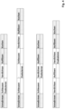
- the first representation of the Figure 2 shows a first embodiment of the evacuation according to the invention.
- the evacuation takes place in a pressure-tight lock, whereby during a process of introducing the shredded wood, an evacuation takes place at least in parts of the lock.
- the treated shredded wood for preheating.
- the second representation of the Figure 2 shows a second embodiment of the evacuation according to the invention.
- the evacuation takes place in a pressure-tight, evacuable space, into which the shredded wood is introduced in a pressure-tight manner on the inlet side and discharged in a pressure-tight manner on the outlet side.
- the shredded wood treated in this way is then passed on for preheating.
- the third representation of the Figure 2 shows a third embodiment of the evacuation according to the invention.
- the evacuation takes place in a pressure-tight evacuatable space, into which the chopped wood is introduced at the inlet, mechanically compacted and evacuated during compaction, whereby a plug is formed at an outlet of the evacuatable space, which is at least partially removed in order to release the chopped wood treated in this way from the evacuatable space for preheating.
- the fourth representation of the Figure 2 shows a fourth embodiment for evacuation according to the invention.
- the chopped wood is mechanically compacted before evacuation, whereby an inlet-side plug is created at an entrance of an evacuable space, which is at least partially removed in order to introduce the chopped wood compacted in this way into the evacuable space, so that the chopped wood is mechanically compacted in the evacuable space and evacuated during compaction, whereby an outlet-side plug is created at an exit of the evacuable space, which is at least partially removed in order to release the chopped wood treated in this way from the evacuable space into the preheater.
- the evacuation of air stored in the shredded wood takes place by means of a negative pressure acting on the shredded wood after the preheating process step.
- the process steps known from the prior art of mechanical compaction and dewatering follow again, whereby a plug is formed, plug at least partially dissolving and cooking.
- the first representation of the Figure 3 shows the second variant of the method according to the invention in interaction with the already explained first embodiment for the evacuation according to the invention.
- the second representation of the Figure 3 shows the second variant of the method according to the invention in interaction with the already explained second embodiment for the evacuation according to the invention.
- the third representation of the Figure 3 shows the second variant of the method according to the invention in cooperation with the already explained third embodiment for the evacuation according to the invention.
- the fourth representation of the Figure 3 shows the second variant of the method according to the invention in cooperation with the already explained fourth embodiment for the evacuation according to the invention.
- This third variant of the process for producing pulp according to the invention is intended for shredded dry wood such as waste wood chips. Since the moisture content of waste wood chips is approximately in a range between 6% and 15%, this third variant according to the invention Variant carried out without a process step for dewatering the shredded wood.
- the evacuation of air stored in the shredded wood by means of a negative pressure acting on the shredded wood takes place again in various embodiments after the process step of preheating and before the process steps of at least partially dissolving a plug previously formed by compaction with or without evacuation.
- the shredded wood is then fed to the digester.
Landscapes
- Life Sciences & Earth Sciences (AREA)
- Engineering & Computer Science (AREA)
- Wood Science & Technology (AREA)
- Forests & Forestry (AREA)
- Physics & Mathematics (AREA)
- Thermal Sciences (AREA)
- Mechanical Engineering (AREA)
- Paper (AREA)
- Dry Formation Of Fiberboard And The Like (AREA)
- Debarking, Splitting, And Disintegration Of Timber (AREA)
Applications Claiming Priority (1)
| Application Number | Priority Date | Filing Date | Title |
|---|---|---|---|
| DE102023123348.3A DE102023123348B3 (de) | 2023-08-30 | 2023-08-30 | Verfahren zur Herstellung von Faserstoff aus zerkleinertem Holz und Anordnung zur Umsetzung des Verfahrens zur Herstellung von Faserstoff aus zerkleinertem Holz |
Publications (2)
| Publication Number | Publication Date |
|---|---|
| EP4516993A2 true EP4516993A2 (fr) | 2025-03-05 |
| EP4516993A3 EP4516993A3 (fr) | 2025-05-28 |
Family
ID=92626588
Family Applications (1)
| Application Number | Title | Priority Date | Filing Date |
|---|---|---|---|
| EP24197199.3A Pending EP4516993A3 (fr) | 2023-08-30 | 2024-08-29 | Procédé de fabrication de matière fibreuse à partir de bois broyé |
Country Status (2)
| Country | Link |
|---|---|
| EP (1) | EP4516993A3 (fr) |
| DE (1) | DE102023123348B3 (fr) |
Family Cites Families (7)
| Publication number | Priority date | Publication date | Assignee | Title |
|---|---|---|---|---|
| DE19509152A1 (de) * | 1994-03-15 | 1995-10-26 | Fraunhofer Ges Forschung | Verfahren zur Wiedergewinnung von Spänen und Fasern aus Holzwerkstoffreststücken, Altmöbeln, Produktionsrückständen, Abfällen und anderen holzwerkstoffhaltigen Materialien |
| AT405038B (de) * | 1996-08-27 | 1999-04-26 | Funder Ind Ges M B H | Verfahren zur aufbereitung von faserplattenabfällen |
| DE19653067A1 (de) * | 1996-11-25 | 1998-06-04 | Nolte Gmbh & Co Kg Spanplatten | Verfahren zur Wiedergewinnung und Weiterverarbeitung spanförmiger Holzwerkstoffe |
| DE19746383A1 (de) * | 1997-10-21 | 1999-04-22 | Hofa Homann Gmbh & Co Kg | Verfahren und Vorrichtung zur Herstellung von Faserplatten sowie nach dem Verfahren hergestellte Faserplatten |
| AT9060U1 (de) * | 2005-12-02 | 2007-04-15 | Iap Industrieanlagen Planungsg | Verfahren zur aufbereitung von ausgangsmaterial zur herstellung von zellstoff, halbzellstoff, oder thermomechanischen holzstoffen sowie vorrichtung hiefür |
| DE102008028350A1 (de) * | 2008-06-13 | 2009-12-17 | BETZ, Günter | Vorrichtung zum Tränken von Fasermaterial mit einer Flüssigkeit |
| WO2015011279A2 (fr) * | 2013-07-25 | 2015-01-29 | Kotyk Energy Ag | Dispositif et procédé de traitement d'une biomasse |
-
2023
- 2023-08-30 DE DE102023123348.3A patent/DE102023123348B3/de active Active
-
2024
- 2024-08-29 EP EP24197199.3A patent/EP4516993A3/fr active Pending
Non-Patent Citations (3)
| Title |
|---|
| ALTHOLZ: "Dissertation", UNIVERSITÄT HAMBURG INSTITUT BIOLOGIE, article "Herstellung von Mitteldichten Faserplatten (MDF" |
| FISCHER, M.KRUG, D.: "Fichtenholz bis in den Kern imprägniert - Brandschutzmittel für sehr schwer imprägnierbare Hölzer entwickelt", TESTERGEBNISSE BEEINDRUCKEN HOLZ-ZENTRALBLATT, vol. 137, no. 35, 2011, pages 846 - 847 |
| ROLL, H: "Optimierung des Faseraufschlusses im Refiner, Energierelevante Aspekte der Refinerscheibentechnologie bei der MDF-Herstellung unter Berücksichtigung der Faserqualität", HOLZ-ZENTRALBLATT, no. 16, 2010, pages 423 - 424 |
Also Published As
| Publication number | Publication date |
|---|---|
| EP4516993A3 (fr) | 2025-05-28 |
| DE102023123348B3 (de) | 2024-12-24 |
Similar Documents
| Publication | Publication Date | Title |
|---|---|---|
| RU2373314C2 (ru) | Установка для изготовления термомеханической древесной массы (варианты), способ термомеханического рафинирования древесной щепы (варианты) и комбинированная плита для диска рафинера | |
| DE19712653C2 (de) | Verfahren und Vorrichtung zur Dispergierung eines Altpapierfaserstoffes | |
| EP1002154B1 (fr) | Procede de pretraitement de matieres contenant des fibres de lignocellulose utile pour procede de fabrication de pate a papier | |
| DE2633041A1 (de) | Verfahren und vorrichtung zum behandeln eines lignozellulose enthaltenden grundmaterials | |
| EP0697941B1 (fr) | Procede de recuperation de copeaux et de fibres par desagregation de residus de materiaux derives du bois, de vieux meubles, de residus de production, de dechets et d'autres materiaux contenant des materiaux derives du bois | |
| DE2053419A1 (de) | Verfahren und Vorrichtung zum Mahlen von Papierstoff | |
| EP2788544B2 (fr) | Procédé de traitement de vieux papiers | |
| DE60208034T2 (de) | Verfahren zur herstellung eines gebleichten tmp- oder ctmp zellstoffs | |
| US20050011622A1 (en) | High defiberization chip pretreatment | |
| DE2752081B2 (de) | Verfahren und Vorrichtung für kontinuierliche Herstellung von Faserbrei oder Stoff aus lignoceUulosehaltigem Fasergut | |
| DE68924652T2 (de) | Vorrichtung zum quetschen von holzspänen. | |
| DE2027319B2 (de) | Verfahren zur Herstellung von chemisch gut löslichem Zellstoff | |
| DE2750600C2 (de) | Verfahren zur Wiedergewinnung von Cellulosefasern aus einer Verbundfolie | |
| DE1291504B (de) | Trockenverfahren zur Herstellung von Holzfasern | |
| AT510109A2 (de) | Verfahren, system und refinder zur mahlung von hackschnitzeln oder zellstofffasern | |
| EP4373647B1 (fr) | Procédé de fabrication de panneau fibreux à émission réduite de cov | |
| EP4516993A2 (fr) | Procédé de fabrication de matière fibreuse à partir de bois broyé | |
| DD291790A5 (de) | Verfahren zur herstellung von lignozellulosehaltigem faserstoff fuer die herstellung von faserplatten nach dem trockenverfahren | |
| WO2025068153A1 (fr) | Procédé et dispositif de production d'une bande fibreuse déposée à sec, en particulier d'une bande de papier, de carton ou de tissu, à partir de balles de cellulose | |
| RU2372433C2 (ru) | Дисковый рафинер (варианты), пара рафинирующих элементов для дискового рафинера (варианты), комбинированная плита дискового рафинера и способ термомеханического рафинирования древесной щепы | |
| EP0826471A2 (fr) | Procédé de traitement pour déchets de panneaux en fibre | |
| DE102023126607A1 (de) | Verfahren und Vorrichtung zur Herstellung einer trockengelegten Faserstoffbahn, insbesondere Papier-, Karton- oder Tissuebahn, aus Ballen-Zellstoff | |
| EP4065763B1 (fr) | Dispositif et procede de maceration d'un materiau a transporter | |
| AT510785B1 (de) | Mechanischer halbstoff sowie ein system und ein verfahren zur produktion mechanischen halbstoffes | |
| EP1727935B1 (fr) | Procede et dispositif de reduction des pertes de vapeur dans un systeme ferme |
Legal Events
| Date | Code | Title | Description |
|---|---|---|---|
| PUAI | Public reference made under article 153(3) epc to a published international application that has entered the european phase |
Free format text: ORIGINAL CODE: 0009012 |
|
| STAA | Information on the status of an ep patent application or granted ep patent |
Free format text: STATUS: THE APPLICATION HAS BEEN PUBLISHED |
|
| AK | Designated contracting states |
Kind code of ref document: A2 Designated state(s): AL AT BE BG CH CY CZ DE DK EE ES FI FR GB GR HR HU IE IS IT LI LT LU LV MC ME MK MT NL NO PL PT RO RS SE SI SK SM TR |
|
| PUAL | Search report despatched |
Free format text: ORIGINAL CODE: 0009013 |
|
| AK | Designated contracting states |
Kind code of ref document: A3 Designated state(s): AL AT BE BG CH CY CZ DE DK EE ES FI FR GB GR HR HU IE IS IT LI LT LU LV MC ME MK MT NL NO PL PT RO RS SE SI SK SM TR |
|
| RIC1 | Information provided on ipc code assigned before grant |
Ipc: B27L 11/08 20060101ALI20250423BHEP Ipc: B27K 1/00 20060101ALI20250423BHEP Ipc: D21D 1/30 20060101ALI20250423BHEP Ipc: D21D 1/20 20060101ALI20250423BHEP Ipc: D21C 1/02 20060101AFI20250423BHEP |
|
| STAA | Information on the status of an ep patent application or granted ep patent |
Free format text: STATUS: REQUEST FOR EXAMINATION WAS MADE |
|
| 17P | Request for examination filed |
Effective date: 20250901 |