EP4516754A1 - Glasscheibe und verfahren zur herstellung einer glasscheibe - Google Patents
Glasscheibe und verfahren zur herstellung einer glasscheibe Download PDFInfo
- Publication number
- EP4516754A1 EP4516754A1 EP23796205.5A EP23796205A EP4516754A1 EP 4516754 A1 EP4516754 A1 EP 4516754A1 EP 23796205 A EP23796205 A EP 23796205A EP 4516754 A1 EP4516754 A1 EP 4516754A1
- Authority
- EP
- European Patent Office
- Prior art keywords
- glass plate
- glare
- principal surface
- ave
- curvingly
- Prior art date
- Legal status (The legal status is an assumption and is not a legal conclusion. Google has not performed a legal analysis and makes no representation as to the accuracy of the status listed.)
- Pending
Links
Images


Classifications
-
- C—CHEMISTRY; METALLURGY
- C03—GLASS; MINERAL OR SLAG WOOL
- C03C—CHEMICAL COMPOSITION OF GLASSES, GLAZES OR VITREOUS ENAMELS; SURFACE TREATMENT OF GLASS; SURFACE TREATMENT OF FIBRES OR FILAMENTS MADE FROM GLASS, MINERALS OR SLAGS; JOINING GLASS TO GLASS OR OTHER MATERIALS
- C03C19/00—Surface treatment of glass, not in the form of fibres or filaments, by mechanical means
-
- B—PERFORMING OPERATIONS; TRANSPORTING
- B24—GRINDING; POLISHING
- B24C—ABRASIVE OR RELATED BLASTING WITH PARTICULATE MATERIAL
- B24C1/00—Methods for use of abrasive blasting for producing particular effects; Use of auxiliary equipment in connection with such methods
- B24C1/04—Methods for use of abrasive blasting for producing particular effects; Use of auxiliary equipment in connection with such methods for treating only selected parts of a surface, e.g. for carving stone or glass
-
- B—PERFORMING OPERATIONS; TRANSPORTING
- B24—GRINDING; POLISHING
- B24C—ABRASIVE OR RELATED BLASTING WITH PARTICULATE MATERIAL
- B24C1/00—Methods for use of abrasive blasting for producing particular effects; Use of auxiliary equipment in connection with such methods
- B24C1/06—Methods for use of abrasive blasting for producing particular effects; Use of auxiliary equipment in connection with such methods for producing matt surfaces, e.g. on plastic materials, on glass
-
- C—CHEMISTRY; METALLURGY
- C03—GLASS; MINERAL OR SLAG WOOL
- C03C—CHEMICAL COMPOSITION OF GLASSES, GLAZES OR VITREOUS ENAMELS; SURFACE TREATMENT OF GLASS; SURFACE TREATMENT OF FIBRES OR FILAMENTS MADE FROM GLASS, MINERALS OR SLAGS; JOINING GLASS TO GLASS OR OTHER MATERIALS
- C03C15/00—Surface treatment of glass, not in the form of fibres or filaments, by etching
-
- C—CHEMISTRY; METALLURGY
- C03—GLASS; MINERAL OR SLAG WOOL
- C03C—CHEMICAL COMPOSITION OF GLASSES, GLAZES OR VITREOUS ENAMELS; SURFACE TREATMENT OF GLASS; SURFACE TREATMENT OF FIBRES OR FILAMENTS MADE FROM GLASS, MINERALS OR SLAGS; JOINING GLASS TO GLASS OR OTHER MATERIALS
- C03C21/00—Treatment of glass, not in the form of fibres or filaments, by diffusing ions or metals in the surface
- C03C21/001—Treatment of glass, not in the form of fibres or filaments, by diffusing ions or metals in the surface in liquid phase, e.g. molten salts, solutions
- C03C21/002—Treatment of glass, not in the form of fibres or filaments, by diffusing ions or metals in the surface in liquid phase, e.g. molten salts, solutions to perform ion-exchange between alkali ions
-
- C—CHEMISTRY; METALLURGY
- C03—GLASS; MINERAL OR SLAG WOOL
- C03C—CHEMICAL COMPOSITION OF GLASSES, GLAZES OR VITREOUS ENAMELS; SURFACE TREATMENT OF GLASS; SURFACE TREATMENT OF FIBRES OR FILAMENTS MADE FROM GLASS, MINERALS OR SLAGS; JOINING GLASS TO GLASS OR OTHER MATERIALS
- C03C2204/00—Glasses, glazes or enamels with special properties
- C03C2204/08—Glass having a rough surface
Definitions
- the present disclosure relates to a glass plate and a method of producing a glass plate.
- the anti-glare treatment is a process for imparting fine irregularities to a principal surface of the glass plate. Reflected light can be diffused by the irregularities, and reflection can be suppressed.
- the anti-glare treatment includes, for example, at least one process selected from frosting, etching, or blasting.
- the anti-glare treatment of Patent Document 1 includes a process of blasting the principal surface of the glass plate by using a mixture of sand grains and water having a chord length of 0.5 ⁇ m to 2 ⁇ m, and a process of etching the principal surface of the glass plate thereafter.
- the anti-glare treatment of Patent Document 2 includes a process of frosting the principal surface of the glass plate, and a process of etching the principal surface of the glass plate thereafter.
- a mixed aqueous solution of ammonium fluoride or potassium fluoride and hydrogen fluoride is used.
- the anti-glare treatment of Patent Document 3 includes a process of blasting the principal surface of the glass plate and a process of etching the principal surface of the glass plate thereafter. Particles having a number of #2000 or higher are used as the particles for the blasting.
- the anti-glare treatment of Patent Document 4 includes a process of blasting the principal surface of the glass plate and a process of etching the principal surface of the glass plate thereafter. Particles having a number of #3000 or higher are used as the particles for the blasting.
- the anti-glare treatment suppresses reflection of surrounding objects, it causes a glare called "sparkle".
- the glare is caused by unevenness acting as fine lenses.
- An embodiment of the present disclosure provides a technique for suppressing the reflection of surrounding objects and suppressing generation of the glare.
- a glass plate includes a first principal surface and a second principal surface facing away from the first principal surface.
- the first principal surface includes an anti-glare surface.
- the anti-glare surface includes a plurality of curvingly-recessed surfaces, each of which has a spoon-cut shape.
- the number N of the recessed surfaces per predetermined area in plan view is 250 surfaces/100 ⁇ m ⁇ or more.
- An average value H AVE of a depth H of the curvingly-recessed surface is 0.10 ⁇ m or more.
- a standard deviation H ⁇ of the depth H is 0.220 ⁇ m or less, and the product H AVE ⁇ H ⁇ of the average value H AVE of the depth H and the standard deviation H ⁇ is 0.085 ⁇ m 2 or less.
- reflection of surrounding objects can be suppressed and occurrence of glare can also be suppressed.
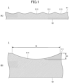
- the glass plate 1 includes the first principal surface 11 and the second principal surface 12 facing away from the first principal surface 11.
- the first principal surface 11 includes an anti-glare surface.
- the anti-glare surface suppresses reflection of surrounding objects (including illumination).
- the entire first principal surface 11 may be the anti-glare surface, or a part of the first principal surface 11 may be the anti-glare surface.
- the glass plate 1 is used as a cover glass of an image display device.
- the image display device is incorporated into portable or fixed electronic equipment.
- the portable electronic equipment is, for example, a cellular phone, a smart phone, an electronic book reader, or a notebook personal computer.
- the fixed electronic equipment is, for example, a desktop personal computer, a digital signage, an in-vehicle display, a television, or an electronic blackboard (IFP).
- IFP electronic blackboard
- the anti-glare surface includes a plurality of spoon-cut curvingly-recessed surfaces 111.
- the surface shape of the anti-glare surface is measured, for example, with a Keyence laser microscope VK-X260 using a 150 ⁇ objective lens in a high-definition mode. Measured surface shape data is analyzed, for example, with image analysis software SPIP (registered trademark) version 5.1.11 manufactured by Image Metrology.
- SPIP registered trademark
- the "Smoothing Filter Size” is set to 17 pixels (1.58 ⁇ m) and the “Finest Filter Size” is set to 7 pixels (0.65 ⁇ m).
- “Slope Noise Reduction” is set to 10% and “Slope Image Threshold Percentile” is set to 0%.
- a "Post Processing” tab is set as follows: “Include Shapes on Border” to on, “Min” of “Z Range” to 0.03 ⁇ m, and “Min” of "Diameter” to 0.80 ⁇ m.
- an "Area” value and “Z Range Output” are obtained.
- the "Area” value is used as the area S of the curvingly-recessed surface 111 in plan view.
- the plan view means a view from a direction perpendicular to the first principal surface 11 and the second principal surface 12.
- the "Z Range Output” is used as a depth H of the curvingly-recessed surface 111.
- the area S and the depth H are obtained for each curvingly-recessed surface 111.
- the anti-glare surface When the surface shape of the anti-glare surface is measured by the laser microscope as described above, and the anti-glare surface is decomposed into a plurality of curvingly-recessed surfaces 111 by the watershed algorithm based on a measured result, the anti-glare surface preferably satisfies the following (A) to (D).
- the anti-glare surface further preferably satisfies (E) in the following.
- (E) The average value S AVE of the area S of the curvingly-recessed surface 111 in plan view is 6 ⁇ m 2 or more and 33 ⁇ m 2 or less.
- S AVE is 33 ⁇ m 2 or less, the appearance of the anti-glare surface can be more homogenized and the glare can be more suppressed.
- S AVE is 6 ⁇ m 2 or more, the reflected light can be more diffused and the reflection of surrounding objects can be more suppressed.
- the S AVE is more preferably 6.5 ⁇ m 2 or more and 23 ⁇ m 2 or less.
- the S AVE is more preferably 7 ⁇ m 2 or more and 17 ⁇ m 2 or less.
- a haze value of the anti-glare surface is preferably 50% or less.
- the haze value is measured with a commercially available measurement device.
- the measurement device and measuring conditions are as follows, for example. Measurement device: Suga Test Instruments Co., Ltd., haze meter HZ-V3. Measuring conditions: The measurement is performed using a C light source in accordance with the Japanese Industrial Standards (JIS K 7136: 2000).
- the haze value is preferably 0% to 50%. When the haze value is 50% or less, clarity of a transmitted image is good.
- the haze value is more preferably 40% or less, more preferably 35% or less, furthermore preferably 30% or less, and more particularly preferably 25% or less.
- a glare index value Sp of the anti-glare surface is preferably 4.6% or less.
- a method of measuring the glare index value Sp is concretely as follows.
- a pixel pattern attached to an SMS-1000 manufactured by D&MS is installed as a photomask on a light emitting surface of a backlight with its pattern surface facing up. Further, the glass plate 1 is installed on the pattern surface of the photomask with its first principal surface 11 facing up.
- a 190 dpi area of the pattern surface of the photomask is imaged through the glass plate 1 by a camera of the measurement device SMS-1000 manufactured by DM&S in a state of simulating a green monochromatic image display formed of RGB (0,255,0).
- a sparkle value obtained by image analysis of the measurement device is the glare index value Sp.
- a measurement is performed in a difference image method (DIM) mode.
- a pixel ratio is adjusted to a height of 9.25, and the measurement is performed in a state of focusing on a pixel surface as much as possible.
- a distance between a light shielding plate attached to the camera and the glass plate 1 is about 262 mm.
- a 23FM50SP lens having a focal distance of 50 mm is used at an aperture of 5.6.
- the glare index value Sp is preferably 0.0% or more and 4.6% or less. When the glare index value Sp is 4.6% or less, occurrence of the glare can be suppressed.
- the glare index value Sp is more preferably 4.3% or less.
- the glare index value Sp is more preferably 4.0% or less.
- An anti-glare index value D of the anti-glare surface is preferably 0.10 or more.
- a method of measuring the anti-glare index value D will be described with reference to FIG. 2 .
- a measurement device 70 includes a linear light source device 71 and a surface luminance measurer 75.
- the linear light source device 71 includes a light source 711 and a black flat plate 712.
- the black flat plate 712 is arranged horizontally and has a rectangular (101 mm ⁇ 1 mm) slit in a vertical direction. The slit is provided with the light source 711.
- the light source 711 is a white light source of a cold cathode tube (CCFL).
- the glass plate 1 is arranged horizontally with its first principal surface 11 facing upward below the linear light source device 71 and the surface luminance measurer 75.
- the surface luminance measurer 75 is arranged on a plane perpendicular to the linear light source device 71 at a longitudinal center of the linear light source device 71.
- a focus of the surface luminance measurer 75 is aligned with an image of the linear light source device 71 reflected by the glass plate 1. That is, a plane on which the image is focused is aligned with the black flat plate 712.
- the black flat plate is brought into contact with the second principal surface 12 of the glass plate 1. Therefore, the light detected by the surface luminance measurer 75 is the light reflected by the glass plate 1.
- ⁇ 0.5°
- the ray 734 is scattered by the glass plate 1 in a direction 0.5° away from regular reflection.
- the ray 734 is observed by the surface luminance measurer 75 as an image of a portion where the black flat plate 712 and an imaginary ray 733-2 intersect.
- the incidence angle of the imaginary ray 733-2 is equal to a reflection angle of the ray 734.
- the surface luminance measurer 75 When a surface luminance is obtained by the surface luminance measurer 75, the luminance of a portion illuminated by the ray 732 specularly reflected by the glass plate 1 becomes the highest, and an emission line appears at that portion. An image with a lower luminance is obtained as it becomes further away from the emission line toward both left and right sides. A luminance at a position away from the emission line becomes a luminance in accordance with the intensity of the ray scattered by the glass plate 1. Therefore, a luminance cross-sectional profile in a direction perpendicular to the emission line is extracted. In order to enhance measurement accuracy, data may be integrated in a direction parallel to the emission line.
- D D2 + D3 / 2 ⁇ D1
- the anti-glare index value D indicates a good correlation with a result of determination of an anti-glare property performed by sight of an observer. For example, the smaller the anti-glare index value D (closer to zero), the poorer the anti-glare property. Conversely, the larger the anti-glare index value D (closer to 1), the better the anti-glare property.
- the measurement of D1, D2, and D3 can be performed, for example, by using a device SMS-1000 manufactured by DM&S.
- a device SMS-1000 manufactured by DM&S When this device is used, a C1614A lens having a focal distance of a camera lens of 16 mm is used at an aperture of 5.6.
- a distance from the first principal surface 11 of the glass plate 1 to the camera lens is about 300 mm, and the Imaging Scale is set within a range of 0.0276 to 0.0278.
- the anti-glare index value D is preferably 0.10 or more and less than 1.00. When the anti-glare index value D is 0.10 or more, reflection of surrounding objects can be suppressed.
- the anti-glare index value D is more preferably 0.12 or more.
- the anti-glare index value D is furthermore preferably 0.15 or more.
- the glass plate 1 may be a flat plate or a curved plate.
- a thickness of the glass plate 1 is preferably 5 mm or less, and more preferably 3 mm or less.
- the thickness of the glass plate 1 is preferably 0.2 mm or more, and more preferably 0.3 mm or more.
- the glass of the glass plate 1 is, for example, aluminosilicate glass, alkali aluminosilicate glass, soda lime glass, borosilicate glass, phosphorus silicate glass, alkali aluminoborosilicate glass, lead glass, alkali barium glass, or aluminoborosilicate glass. More specifically, the following glasses (i) to (v) are mentioned.
- the method of producing the glass plate 1 includes performing wet blasting (step S101) and wet etching (step S102) at least on a portion of the first principal surface 11 of the glass plate 1 in this order to obtain an anti-glare surface.
- the method of producing the glass plate 1 may include processes other than steps S101 and S102.
- the glass plate 1 may be chemically strengthened.
- a chemically strengthening process is a process of forming a compressive stress layer on a glass surface by ion exchange at a temperature equal to or lower than a glass transition point.
- the compressive stress layer is formed by exchanging alkali metal ions having a small ionic radius contained in the glass with alkali ions having a larger ionic radius.
- Step S101 includes performing wet blasting at least on a portion of the first principal surface 11 of the glass plate 1.
- the wet blasting is a process of forming minute cracks (microcracks) in an object by jetting a slurry containing particles from a nozzle under pressure of a gas and impinging on the object.
- the slurry includes particles described in the following and a dispersion medium.
- the dispersion medium include water, a water-soluble organic solvent, or a mixture of water and a water-soluble organic solvent.
- the water-soluble organic solvent include lower alcohols and ketones.
- the lower alcohols include methanol, ethanol, n-propanol, isopropanol, n-butanol, sec-butanol, or tert-butanol.
- One example of the ketones is acetone.
- the slurry may also contain a dispersion aid.
- the dispersion aid include carboxymethyl cellulose, a polyacrylic acid derivative or a salt thereof, a polycarboxylic acid derivative or a salt thereof, or polyureurethane.
- the polyacrylic acid derivative or the salt thereof include polyacrylic acid, a polyacrylic acid ammonium salt, a polyacrylic acid sodium salt, a polyacrylamide, an acrylic ester-acrylate copolymer, an acrylamide-acrylate copolymer, or a copolymer of an acrylic ester acrylamide-acrylate salt.
- the polycarboxylic acid derivative or a salt thereof include a polycarboxylic acid ammonium salt or a polycarboxylic acid sodium salt.
- a ratio of the dispersion aid in the slurry is preferably 0.03 mass% or more and 2.0 mass% or less.
- the particles contained in the slurry are preferably particles having higher Mohs hardness than glass from a viewpoint of processability, and are preferably inorganic particles other than spherical particles.
- the inorganic particles may be made of a metal (containing alloys) or an inorganic compound.
- the inorganic compound may be a metal compound or a non-metal compound. Examples of the metal include stainless steel, zinc, copper, and the like. Examples of the inorganic compound include silica, glass, garnet, zirconia, alumina, silicon carbide, boron carbide, CO 2 (dry ice), and the like. Among these, alumina is preferable.
- a commercial product can be used as the particles contained in the slurry. Examples of the commercial product include white alumina manufactured by Fujimi Incorporated.
- the concentration of the particles in the slurry is preferably 0.05 mass% or higher from the viewpoint of productivity, and more preferably 0.1 mass% or higher.
- the concentration of the particles in the slurry is preferably 30 mass% or lower, and more preferably 10 mass% or lower from a viewpoint of fluidity of the slurry.
- the wet blasting can use particles having a smaller particle diameter d than dry blasting, and can form a large number of microcracks (microcracks).
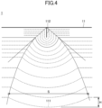
- step S102 described in the following the glass is etched isotropically starting from the microcrack 112 as illustrated in FIG. 4 , so that the curvingly-recessed surface 111 can be formed.
- a plurality of broken lines indicate changes in the surface shape of the glass with time.
- the depth H of the curvingly-recessed surface 111 is equivalent to a depth of the microcrack 112.
- the depth of the microcrack 112 varies depending on the particle diameter d of the particles.
- the particles contained in the slurry preferably have an average value d AVE of the particle diameter d (hereinafter, also referred to as average particle diameter d AVE ) of 2.00 ⁇ m or more.
- average particle diameter d AVE is 2.00 ⁇ m or more
- (C) an anti-glare surface having an average value H AVE of the depth H of the curvingly-recessed surface 111, of 0.10 ⁇ m or more is obtained.
- a length of processing time of the microcrack 112 can be shortened and processability of the microcrack 112 can be enhanced.
- the average particle diameter d AVE is more preferably 2.05 ⁇ m or more.
- the average particle diameter d AVE is furthermore preferably 2.10 ⁇ m or more.
- the particles contained in the slurry preferably have the average particle diameter d AVE of 4.50 ⁇ m or smaller.
- the average particle diameter d AVE is 4.50 ⁇ m or smaller, an antiglare surface in which the average depth of the microcracks 112 is small and the average value S AVE of (E) the area S is 6 ⁇ m 2 or more and 33 ⁇ m 2 or lower, can be obtained.
- the average particle diameter d AVE is more preferably 4.00 ⁇ m or smaller.
- the average particle diameter d AVE is furthermore preferably 3.50 ⁇ m or smaller.
- the average particle diameter d AVE is still more preferably 3.00 ⁇ m or smaller.
- coefficient of variation d CV standard deviation d ⁇ /average value d AVE
- the depth of the microcracks 112 can be made uniform.
- (D) an anti-glare surface in which the standard deviation H ⁇ of the depth H is 0.220 ⁇ m or less and a product H AVE ⁇ H ⁇ of the average value H AVE of the depth H and the standard deviation H ⁇ is 0.085 ⁇ m 2 or smaller is obtained.
- the depth of the microcracks 112 uniform, the area S of the curvingly-recessed surface 111 in plan view is also made uniform, and (A) an anti-glare surface in which the standard deviation S ⁇ of the area S of the curvingly-recessed surface 111 in plan view is 32.5 ⁇ m 2 or smaller is obtained. Further, a proportion of the microcracks 112 whose depth does not reach a specified value is decreased, the proportion of the microcracks 112 whose depth is at least the specified value is increased, and (C) an anti-glare surface in which the average value H AVE of the depth H of the curvingly-recessed surface 111 is 0.10 ⁇ m or more is obtained.
- the coefficient of variation d CV is more preferably 0.360 or less, further more preferably 0.320 or less, and particularly preferably 0.250 or less.
- the coefficient of variation d CV is preferably equal to or more than 0.030, and more preferably equal to or more than 0.060 from the viewpoint of workability of the classification work.
- the depth of the microcracks 112 uniform, the area S of the curvingly-recessed surface 111 in plan view is also made uniform, and (Aa) an anti-glare surface in which (a) the standard deviation S ⁇ of the area S of the curvingly-recessed surface 111 in plan view is equal to or less than 14.5 ⁇ m 2 is obtained. Further, the proportion of the microcracks 112 whose depth does not reach the specified value is decreased, the proportion of the microcracks 112 whose depth is equal to or more than the specified value is increased, and (C) an anti-glare surface in which the average value H AVE of the depth H of the curvingly-recessed surface 111 is equal to or more than 0.10 ⁇ m is obtained.
- Particles are pre-classified so that the coefficient of variation d CV is equal to or less than 0.400, and more preferably equal to or less than 0.250.
- a method of classification is not particularly limited, but examples include classification by sieving, gravity classification (horizontal flow, vertical upward flow), inertial force field classification (linear, curved, and graded), centrifugal force field classification (free vortex type vortex flow and forced vortex flow), and the like.
- the particle size distribution of the particles contained in the slurry is measured using, for example, an electric resistance type particle size distribution measurement device Multisizer 4e manufactured by Beckman Coulter, Inc.
- the particle size distribution obtained using the particle size distribution measurement device described above is based on a so-called "Coulter principle", in which an impedance change due to passage of each particle in an electrolyte solution through a measurement site is directly detected, the particle size of each particle is measured as a spherical equivalent particle size, and particle distribution is arranged in an integrated histogram (or an integrated frequency curve) with the particle size as a horizontal axis and the number (frequency) as a vertical axis.
- the average particle diameter d AVE is calculated as a so-called arithmetic average diameter, according to the number distribution.
- the number of microcracks 112 per unit area can be adjusted by a scanning speed or number of scans of a nozzle.
- the number of scans is the number of times the ray of the nozzle passes the same place on a glass surface.
- the number of microcracks 112 per unit area can be adjusted so as to obtain an anti-glare surface in which (B) the number N of curvingly-recessed surfaces 111 per predetermined area is 250 surfaces/100 ⁇ m ⁇ or more in plan view.
- the depth of the microcracks 112 can be adjusted not only by a material of the particles and the particle diameter d of the particles but also by an injection pressure or a projection distance.
- the injection pressure gas pressure
- the projection distance is preferably 10 mm to 50 mm, and more preferably 20 mm to 40 mm.
- Step S102 includes performing wet etching on at least a portion of the first principal surface 11 of the glass plate 1.
- the wet etching is a process in which an etchant containing an acid or an alkali is supplied to the first principal surface 11 of the glass plate 1 to form a curvingly-recessed surface 111 starting from the microcrack 112.
- a method of supplying the etchant may be a dip method in which the glass plate is immersed in the etchant, or a spray method in which the etchant is applied to the glass plate.
- the wet etching enables isotropic etching of glass as compared with dry etching.
- the etchant is, for example, a solution containing an acid.
- An acid concentration in the etchant is preferably 1 to 15 mass%, and particularly preferably 3 to 10 mass%.
- the acid for example, hydrogen fluoride is used.
- a combination of hydrogen fluoride and hydrogen chloride may be used.
- etching is preferably performed at a temperature of 10°C to 40°C, preferably 15°C to 35°C, for 2 to 20 minutes.
- an etching rate is preferably 0.5 ⁇ m/minute or more, more preferably 1.0 ⁇ m/minute or more, and still more preferably 2.0 ⁇ m/minute or more, from the viewpoint of sufficiently securing an anti-glare effect.
- the etching rate is preferably 20 ⁇ m/minute or less.
- the etchant may be a solution containing alkali.
- An alkali concentration in the etchant is preferably 1 mass% to 50 mass%, and preferably 3 mass% to 50 mass%.
- As the alkali at least one base selected from, for example, sodium hydroxide, potassium hydroxide, potassium carbonate, or sodium carbonate is used. These bases may be used alone or in combination.
- the etchant preferably contains a chelating agent in addition to the alkali.
- the chelating agent suppresses recrystallization of the glass by forming a chelating complex with a metal ion of the glass dissolved in the etchant.
- a content of the chelating agent in the etchant is preferably from 0.1 mol/L to 0.5 mol/L.
- the chelating agent for example, ethylenediaminetetraacetic acid (EDTA), citric acid, gluconic acid, succinic acid, oxalic acid, tartaric acid, or hydroxyethylidenediphosphinic acid (HEDP) is used.
- EDTA ethylenediaminetetraacetic acid
- HEDP hydroxyethylidenediphosphinic acid
- etching is preferably performed at a temperature of from 65°C to 150°C, preferably from 80°C to 150°C, for 20 minutes to 40 hours.
- the etching rate is preferably at least 0.05 um/minute, more preferably at least 0.10 um/minute, and still more preferably at least 0.15 um/minute from the viewpoint of sufficiently securing the anti-glare effect.
- the etching rate is preferably 1.50 ⁇ m/min or less.
- anti-glare glass was prepared by subjecting the first principal surface of a glass plate to wet blasting, wet etching, and a chemical strengthening treatment in this order.
- a product name: Dragontrail (registered trademark) manufactured by AGC Inc. was prepared.
- the size of the glass plate was 100 mm ⁇ 100 mm, and the thickness was 1.0 mm.
- a wet blasting device manufactured by MACOHO Co., Ltd., device name: Jr.Type II
- the slurry was prepared by mixing ceramic particles, a dispersion aid, and water as a dispersion medium.
- the content of ceramic particles (slurry concentration) in the whole slurry was 1.1 wt%.
- the ceramic particles were prepared by classifying white alumina (particle size #4000) manufactured by Fujimi Incorporated.
- the average particle diameter d AVE was 2.64 ⁇ m, and the coefficient of variation d CV was 0.148.
- the injection pressure (gas pressure) of the slurry was 0.25 MPa, the projection distance (distance between the nozzle and the glass plate) was 30 mm, the scanning speed of the nozzle was 200 mm/sec, and the number of nozzle scans was 20.
- the slurry was injected together with compressed air.
- the gas pressure means a pressure of the compressed air. After the wet blasting and before the wet etching, pure water washing and drying were performed.
- the glass plate was immersed in an etchant at 25°C for 286 seconds to etch the first principal surface of the glass plate by 15.9 ⁇ m.
- the second principal surface of the glass plate was protected by an acid-resistant protective film which was pasted in advance.
- the etchant was an aqueous solution containing 5 mass% hydrogen fluoride and 5 mass% hydrogen chloride. After the wet etching, the protective film was peeled off before the chemical strengthening process.
- the glass plate was immersed in a molten salt of potassium nitrate heated at 450°C for 1 hour. Then, the glass plate was pulled out of the molten salt and slowly cooled to room temperature in 1 hour. As a result, a compressive stress layer was formed on both the first and second principal surfaces of the glass plate.
- anti-glare glass was prepared under the same conditions as in Example 1 except that ceramic particles (classified white alumina (particle size #6000) manufactured by Fujimi Incorporated) having the average particle diameter d AVE of 2.22 ⁇ m and the coefficient of variation d CV of 0.119 were used in the wet blasting, and that the first principal surface of the glass plate was etched by 13.6 ⁇ m by immersing the glass plate in the etchant at 25°C for 240 seconds in the wet etching.
- ceramic particles classified white alumina (particle size #6000) manufactured by Fujimi Incorporated) having the average particle diameter d AVE of 2.22 ⁇ m and the coefficient of variation d CV of 0.119 were used in the wet blasting, and that the first principal surface of the glass plate was etched by 13.6 ⁇ m by immersing the glass plate in the etchant at 25°C for 240 seconds in the wet etching.
- anti-glare glass was prepared under the same conditions as in Example 1 except that the first principal surface of the glass plate was etched by 23.4 ⁇ m by immersing the glass plate in the etchant at 25°C for 436 seconds in the wet etching.
- anti-glare glass was prepared under the same conditions as in Example 1 except that ceramic particles (classified white alumina (particle size #6000) manufactured by Fujimi Incorporated) having the average particle diameter d AVE of 2.22 ⁇ m and the coefficient of variation d CV of 0.119 were used in the wet blasting, and that the first principal surface of the glass plate was etched by 20.6 ⁇ m by immersing the glass plate in the etchant at 25°C for 360 seconds in the wet etching.
- ceramic particles classified white alumina (particle size #6000) manufactured by Fujimi Incorporated) having the average particle diameter d AVE of 2.22 ⁇ m and the coefficient of variation d CV of 0.119 were used in the wet blasting, and that the first principal surface of the glass plate was etched by 20.6 ⁇ m by immersing the glass plate in the etchant at 25°C for 360 seconds in the wet etching.
- anti-glare glass was prepared under the same conditions as in Example 1 except that ceramic particles (classified white alumina (particle size #4000) manufactured by Fujimi Incorporated) having the average particle diameter d AVE of 3.04 ⁇ m and the coefficient of variation d CV of 0.107 were used in the wet blasting, the slurry concentration was 0.2 wt%, the number of nozzle scans was 25, and the first principal surface of the glass plate was etched by 20.8 ⁇ m by immersing the glass plate in the etchant at 25°C for 360 seconds in the wet etching.
- ceramic particles classified white alumina (particle size #4000) manufactured by Fujimi Incorporated) having the average particle diameter d AVE of 3.04 ⁇ m and the coefficient of variation d CV of 0.107 were used in the wet blasting
- the slurry concentration was 0.2 wt%
- the number of nozzle scans was 25, and the first principal surface of the glass plate was etched by 20.8 ⁇ m by immersing the glass
- Example 6 anti-glare glass was prepared under the same conditions as in Example 5 except that the first principal surface of the glass plate was etched by 27.2 ⁇ m by immersing the glass plate in the etchant at 25°C for 480 seconds in the wet etching.
- anti-glare glass was prepared under the same conditions as in Example 5 except that the slurry concentration was 1.1 wt%, the number of nozzle scans was 20, and the first principal surface of the glass plate was etched by 19.7 ⁇ m by immersing the glass plate in the etchant at 25°C for 360 seconds in the wet etching.
- anti-glare glass was prepared under the same conditions as in Example 7 except that the first principal surface of the glass plate was etched by 25.3 ⁇ m by immersing the glass plate in the etchant at 25°C for 480 seconds in the wet etching.
- anti-glare glass was prepared under the same conditions as in Example 1 except that ceramic particles (not-classified white alumina (particle size #4000) manufactured by Fujimi Incorporated) having the average particle diameter d AVE of 3.01 ⁇ m and the coefficient of variation d CV of 0.262 were used in the wet blasting, the slurry concentration was 0.2 wt%, and the first principal surface of the glass plate was etched by 26.3 ⁇ m by immersing the glass plate in the etchant at 25°C for 480 seconds in the wet etching.
- ceramic particles not-classified white alumina (particle size #4000) manufactured by Fujimi Incorporated) having the average particle diameter d AVE of 3.01 ⁇ m and the coefficient of variation d CV of 0.262 were used in the wet blasting
- the slurry concentration was 0.2 wt%
- the first principal surface of the glass plate was etched by 26.3 ⁇ m by immersing the glass plate in the etchant at 25°C for
- anti-glare glass was prepared under the same conditions as in Example 1 except that ceramic particles (not-classified white alumina (particle size #6000) manufactured by Fujimi Incorporated) having the average particle diameter d AVE of 2.06 ⁇ m and the coefficient of variation d CV of 0.315 were used in the wet blasting, and the first principal surface of the glass plate was etched by 24.9 ⁇ m by immersing the glass plate in the etchant at 25°C for 480 seconds in the wet etching.
- ceramic particles not-classified white alumina (particle size #6000) manufactured by Fujimi Incorporated) having the average particle diameter d AVE of 2.06 ⁇ m and the coefficient of variation d CV of 0.315 were used in the wet blasting, and the first principal surface of the glass plate was etched by 24.9 ⁇ m by immersing the glass plate in the etchant at 25°C for 480 seconds in the wet etching.
- anti-glare glass was prepared by applying frosting, wet etching, and a chemical strengthening process to the first principal surface of the glass plate in this order.
- a product name: Dragontrail (registered trademark) manufactured by AGC Inc. was prepared as the glass plate.
- the size of the glass plate was 100 mm ⁇ 100 mm and the thickness was 1.0 mm.
- the glass plate was immersed in a chemical solution at 25°C for 3 minutes.
- the second principal surface of the glass plate was protected with the acid-resistant protective film which was pasted in advance.
- the chemical solution was an aqueous solution containing 8 wt% hydrogen fluoride and 8 wt% potassium fluoride. After the frosting, pure water cleaning and drying were performed before the wet etching.
- the glass plate was immersed in the etchant at 25°C for 3 minutes.
- the second principal surface of the glass plate was protected with the acid-resistant protective film.
- the etchant was an aqueous solution containing 10 wt% hydrogen fluoride. After the wet etching, the protective film was peeled off before the chemical strengthening process.
- the glass plate was immersed in a molten salt of potassium nitrate heated to 450°C for 1 hour. Then, the glass plate was pulled out of the molten salt and slowly cooled to room temperature for 1 hour. As a result, a compressive stress layer was formed on both the first and second principal surfaces of the glass plate.
- anti-glare glass was prepared under the same conditions as in Example 1 except that ceramic particles (MACOHO beads (product number: AX-3-15) manufactured by MACOHO Co., Ltd.) having the average particle diameter d AVE of 4.74 ⁇ m and the coefficient of variation d CV of 0.483 were used in the wet blasting, and the first principal surface of the glass plate was etched by 20.3 ⁇ m by immersing the glass plate in the etchant at 25°C for 360 seconds in the wet etching.
- ceramic particles (MACOHO beads (product number: AX-3-15) manufactured by MACOHO Co., Ltd.) having the average particle diameter d AVE of 4.74 ⁇ m and the coefficient of variation d CV of 0.483 were used in the wet blasting, and the first principal surface of the glass plate was etched by 20.3 ⁇ m by immersing the glass plate in the etchant at 25°C for 360 seconds in the wet etching.
- anti-glare glass was prepared under the same conditions as in Example 12 except that the first principal surface of the glass plate was etched by 27.2 ⁇ m by immersing the glass plate in the etchant at 25°C for 480 seconds in the wet etching.
- Example 1 The processing conditions and processing results of Examples 1 to 13 are summarized in Table 1.
- the particle size distribution of alumina particles used in the wet blasting of Examples 1 to 10 and Examples 12 and 13 is illustrated in FIG. 5 .
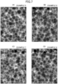
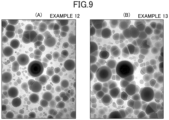
- the surface shapes of the anti-glare surfaces of Examples 1 to 13 were measured with a laser microscope VK-X260 manufactured by KEYENCE CORPORATION, and the results of analysis with image analysis software SPIP (registered trademark) version 5.1.11 manufactured by Image Metrology A/S are as illustrated in FIGS. 6 to 9 .
- the images as illustrated in FIGS. 6 to 9 are images of rectangular areas (length of a long side: 94.9 ⁇ m, length of a short side: 71.2 ⁇ m). In FIGS.
- Example 1 As summarized in Table 1, in Examples 1 to 10, unlike Examples 12 and 13, wet blasting using a slurry containing particles having the average particle diameter d AVE of 2.00 ⁇ m or more and the coefficient of variation d CV of 0.400 or less, and wet etching were performed in this order. As illustrated in FIG. 5 , in Examples 1 to 10, variations in the particle size of alumina particles were smaller than those in Examples 12 and 13. In Example 11, wet blasting was not performed.
- the antiglare surfaces of Examples 1 to 10 had (A) S ⁇ of 32.5 ⁇ m 2 or less, (B) N of 250 surfaces/100 ⁇ m ⁇ or more, (C) H AVE of 0.10 ⁇ m or more, and (D) H ⁇ of 0.220 ⁇ m or less and H AVE ⁇ H ⁇ of 0.085 ⁇ m 2 or less. Therefore, unlike in Examples 11 to 13, the antiglare surfaces of Examples 1 to 10 had the glare index value Sp of 4.6% or less and the anti-glare index value D of 0.10 or more.
- the antiglare surfaces of Examples 1 to 8 differed from the antiglare surfaces of Examples 9 and 10 in that (Aa) S ⁇ was 14.5 ⁇ m 2 or less, (Ba) N was 450 surfaces/100 ⁇ m ⁇ or more, (C) H AVE was 0.10 ⁇ m or more, (Da) H ⁇ was 0.180 ⁇ m or less, and H AVE ⁇ H ⁇ was 0.070 ⁇ m 2 or less. Therefore, the antiglare surfaces of Examples 1 to 8 differed from the antiglare surfaces of Examples 9 and 10 in that the glare index value Sp was 4.0% or less and the anti-glare index value D was 0.10 or more.
Landscapes
- Engineering & Computer Science (AREA)
- Chemical & Material Sciences (AREA)
- Mechanical Engineering (AREA)
- Life Sciences & Earth Sciences (AREA)
- Chemical Kinetics & Catalysis (AREA)
- General Chemical & Material Sciences (AREA)
- Geochemistry & Mineralogy (AREA)
- Materials Engineering (AREA)
- Organic Chemistry (AREA)
- Surface Treatment Of Glass (AREA)
- Optical Elements Other Than Lenses (AREA)
Applications Claiming Priority (2)
| Application Number | Priority Date | Filing Date | Title |
|---|---|---|---|
| JP2022075351 | 2022-04-28 | ||
| PCT/JP2023/015636 WO2023210463A1 (ja) | 2022-04-28 | 2023-04-19 | ガラス板およびガラス板の製造方法 |
Publications (2)
| Publication Number | Publication Date |
|---|---|
| EP4516754A1 true EP4516754A1 (de) | 2025-03-05 |
| EP4516754A4 EP4516754A4 (de) | 2026-04-29 |
Family
ID=88518646
Family Applications (1)
| Application Number | Title | Priority Date | Filing Date |
|---|---|---|---|
| EP23796205.5A Pending EP4516754A4 (de) | 2022-04-28 | 2023-04-19 | Glasscheibe und verfahren zur herstellung einer glasscheibe |
Country Status (6)
| Country | Link |
|---|---|
| US (1) | US20250042808A1 (de) |
| EP (1) | EP4516754A4 (de) |
| JP (1) | JPWO2023210463A1 (de) |
| CN (1) | CN118973976A (de) |
| TW (1) | TW202346236A (de) |
| WO (1) | WO2023210463A1 (de) |
Families Citing this family (1)
| Publication number | Priority date | Publication date | Assignee | Title |
|---|---|---|---|---|
| CN121399078A (zh) * | 2023-06-28 | 2026-01-23 | Agc株式会社 | 玻璃板及其制造方法、车载用显示装置、以及选择玻璃板的方法 |
Family Cites Families (10)
| Publication number | Priority date | Publication date | Assignee | Title |
|---|---|---|---|---|
| US9446979B2 (en) * | 2011-11-02 | 2016-09-20 | Corning Incorporated | Method for sparkle control and articles thereof |
| JP2016040211A (ja) * | 2014-08-12 | 2016-03-24 | 武蔵野ファインガラス株式会社 | アンチグレアガラスの製造方法 |
| JP2019218217A (ja) | 2016-10-20 | 2019-12-26 | Agc株式会社 | ガラス板 |
| CN110753862A (zh) | 2017-06-15 | 2020-02-04 | Agc株式会社 | 透明基体 |
| DE112018003147T5 (de) | 2017-06-20 | 2020-03-05 | AGC Inc. | Glasplatte |
| JP7067077B2 (ja) * | 2018-01-18 | 2022-05-16 | Agc株式会社 | ガラス板及び表示装置 |
| JP7293662B2 (ja) * | 2018-01-25 | 2023-06-20 | 日本電気硝子株式会社 | 表示装置のカバー部材 |
| WO2020067134A1 (ja) * | 2018-09-25 | 2020-04-02 | 日本電気硝子株式会社 | 透明物品 |
| CN111333340B (zh) | 2018-12-18 | 2024-04-05 | 欧浦登(顺昌)光学有限公司 | 一种高清晰度无闪烁蚀刻玻璃及其制造工艺和应用 |
| JP7641554B2 (ja) | 2020-11-06 | 2025-03-07 | パナソニックIpマネジメント株式会社 | 充電管理システム、電力管理システム、充電管理方法、及びプログラム |
-
2023
- 2023-04-19 EP EP23796205.5A patent/EP4516754A4/de active Pending
- 2023-04-19 CN CN202380034592.6A patent/CN118973976A/zh active Pending
- 2023-04-19 JP JP2024517237A patent/JPWO2023210463A1/ja active Pending
- 2023-04-19 WO PCT/JP2023/015636 patent/WO2023210463A1/ja not_active Ceased
- 2023-04-21 TW TW112114991A patent/TW202346236A/zh unknown
-
2024
- 2024-10-18 US US18/919,565 patent/US20250042808A1/en active Pending
Also Published As
| Publication number | Publication date |
|---|---|
| EP4516754A4 (de) | 2026-04-29 |
| WO2023210463A1 (ja) | 2023-11-02 |
| US20250042808A1 (en) | 2025-02-06 |
| JPWO2023210463A1 (de) | 2023-11-02 |
| CN118973976A (zh) | 2024-11-15 |
| TW202346236A (zh) | 2023-12-01 |
Similar Documents
| Publication | Publication Date | Title |
|---|---|---|
| US10899661B2 (en) | Glass having antiglare surface with low display sparkle | |
| EP2477954B1 (de) | Glas mit blendschutzeigenschaften | |
| EP3246297A1 (de) | Blendfreier glasscheibenartikel für eine anzeigevorrichtung und verfahren zur herstellung davon | |
| EP3083519B1 (de) | Strukturierte oberflächen für anzeigeanwendungen | |
| US12404207B2 (en) | Textured, antiglare glass articles and methods of making the same | |
| US11236016B2 (en) | Chemically strengthened glass | |
| JP6181383B2 (ja) | 防眩フィルム | |
| EP3524581A2 (de) | Glasartikel und verfahren zur herstellung davon | |
| KR20140005197A (ko) | 눈 부심 방지 표면 처리 방법 및 이의 제품 | |
| US20250042808A1 (en) | Glass plate and method of producing glass plate | |
| EP3912965A1 (de) | Gradientenglas, verfahren zu seiner herstellung und seine verwendung | |
| CN112897888A (zh) | 具有纹理化表面的玻璃基材的制造方法 | |
| CN104936920A (zh) | 透明基材 | |
| CN121444639A (zh) | 防眩盖板的制造方法、oled显示器单元的制造方法、防眩盖板和oled显示器单元 | |
| CN115003639B (zh) | 玻璃基板、显示装置和玻璃基板的制造方法 | |
| US20230365463A1 (en) | Method for producing chemically strengthened glass substrate, method for reworking chemically strengthened glass substrate, and chemically strengthened glass substrate |
Legal Events
| Date | Code | Title | Description |
|---|---|---|---|
| STAA | Information on the status of an ep patent application or granted ep patent |
Free format text: STATUS: THE INTERNATIONAL PUBLICATION HAS BEEN MADE |
|
| PUAI | Public reference made under article 153(3) epc to a published international application that has entered the european phase |
Free format text: ORIGINAL CODE: 0009012 |
|
| STAA | Information on the status of an ep patent application or granted ep patent |
Free format text: STATUS: REQUEST FOR EXAMINATION WAS MADE |
|
| 17P | Request for examination filed |
Effective date: 20241121 |
|
| AK | Designated contracting states |
Kind code of ref document: A1 Designated state(s): AL AT BE BG CH CY CZ DE DK EE ES FI FR GB GR HR HU IE IS IT LI LT LU LV MC ME MK MT NL NO PL PT RO RS SE SI SK SM TR |
|
| DAV | Request for validation of the european patent (deleted) | ||
| DAX | Request for extension of the european patent (deleted) |