EP4516711A1 - Printer - Google Patents
Printer Download PDFInfo
- Publication number
- EP4516711A1 EP4516711A1 EP23795893.9A EP23795893A EP4516711A1 EP 4516711 A1 EP4516711 A1 EP 4516711A1 EP 23795893 A EP23795893 A EP 23795893A EP 4516711 A1 EP4516711 A1 EP 4516711A1
- Authority
- EP
- European Patent Office
- Prior art keywords
- path
- paper
- flap
- printing
- discharge
- Prior art date
- Legal status (The legal status is an assumption and is not a legal conclusion. Google has not performed a legal analysis and makes no representation as to the accuracy of the status listed.)
- Pending
Links
Images







Classifications
-
- B—PERFORMING OPERATIONS; TRANSPORTING
- B41—PRINTING; LINING MACHINES; TYPEWRITERS; STAMPS
- B41J—TYPEWRITERS; SELECTIVE PRINTING MECHANISMS, i.e. MECHANISMS PRINTING OTHERWISE THAN FROM A FORME; CORRECTION OF TYPOGRAPHICAL ERRORS
- B41J13/00—Devices or arrangements of selective printing mechanisms, e.g. ink-jet printers or thermal printers, specially adapted for supporting or handling copy material in short lengths, e.g. sheets
- B41J13/009—Diverting sheets at a section where at least two sheet conveying paths converge, e.g. by a movable switching guide that blocks access to one conveying path and guides the sheet to another path, e.g. when a sheet conveying direction is reversed after printing on the front of the sheet has been finished and the sheet is guided to a sheet turning path for printing on the back
-
- B—PERFORMING OPERATIONS; TRANSPORTING
- B41—PRINTING; LINING MACHINES; TYPEWRITERS; STAMPS
- B41J—TYPEWRITERS; SELECTIVE PRINTING MECHANISMS, i.e. MECHANISMS PRINTING OTHERWISE THAN FROM A FORME; CORRECTION OF TYPOGRAPHICAL ERRORS
- B41J11/00—Devices or arrangements of selective printing mechanisms, e.g. ink-jet printers or thermal printers, for supporting or handling copy material in sheet or web form
- B41J11/66—Applications of cutting devices
- B41J11/70—Applications of cutting devices cutting perpendicular to the direction of paper feed
-
- B—PERFORMING OPERATIONS; TRANSPORTING
- B41—PRINTING; LINING MACHINES; TYPEWRITERS; STAMPS
- B41J—TYPEWRITERS; SELECTIVE PRINTING MECHANISMS, i.e. MECHANISMS PRINTING OTHERWISE THAN FROM A FORME; CORRECTION OF TYPOGRAPHICAL ERRORS
- B41J2/00—Typewriters or selective printing mechanisms characterised by the printing or marking process for which they are designed
- B41J2/315—Typewriters or selective printing mechanisms characterised by the printing or marking process for which they are designed characterised by selective application of heat to a heat sensitive printing or impression-transfer material
- B41J2/32—Typewriters or selective printing mechanisms characterised by the printing or marking process for which they are designed characterised by selective application of heat to a heat sensitive printing or impression-transfer material using thermal heads
- B41J2/325—Typewriters or selective printing mechanisms characterised by the printing or marking process for which they are designed characterised by selective application of heat to a heat sensitive printing or impression-transfer material using thermal heads by selective transfer of ink from ink carrier, e.g. from ink ribbon or sheet
-
- B—PERFORMING OPERATIONS; TRANSPORTING
- B41—PRINTING; LINING MACHINES; TYPEWRITERS; STAMPS
- B41J—TYPEWRITERS; SELECTIVE PRINTING MECHANISMS, i.e. MECHANISMS PRINTING OTHERWISE THAN FROM A FORME; CORRECTION OF TYPOGRAPHICAL ERRORS
- B41J3/00—Typewriters or selective printing or marking mechanisms characterised by the purpose for which they are constructed
- B41J3/60—Typewriters or selective printing or marking mechanisms characterised by the purpose for which they are constructed for printing on both faces of the printing material
-
- B—PERFORMING OPERATIONS; TRANSPORTING
- B65—CONVEYING; PACKING; STORING; HANDLING THIN OR FILAMENTARY MATERIAL
- B65H—HANDLING THIN OR FILAMENTARY MATERIAL, e.g. SHEETS, WEBS, CABLES
- B65H29/00—Delivering or advancing articles from machines; Advancing articles to or into piles
- B65H29/58—Article switches or diverters
-
- B—PERFORMING OPERATIONS; TRANSPORTING
- B65—CONVEYING; PACKING; STORING; HANDLING THIN OR FILAMENTARY MATERIAL
- B65H—HANDLING THIN OR FILAMENTARY MATERIAL, e.g. SHEETS, WEBS, CABLES
- B65H85/00—Recirculating articles, i.e. feeding each article to, and delivering it from, the same machine work-station more than once
-
- B—PERFORMING OPERATIONS; TRANSPORTING
- B41—PRINTING; LINING MACHINES; TYPEWRITERS; STAMPS
- B41J—TYPEWRITERS; SELECTIVE PRINTING MECHANISMS, i.e. MECHANISMS PRINTING OTHERWISE THAN FROM A FORME; CORRECTION OF TYPOGRAPHICAL ERRORS
- B41J11/00—Devices or arrangements of selective printing mechanisms, e.g. ink-jet printers or thermal printers, for supporting or handling copy material in sheet or web form
- B41J11/0005—Curl smoothing, i.e. smoothing down corrugated printing material, e.g. by pressing means acting on wrinkled printing material
-
- B—PERFORMING OPERATIONS; TRANSPORTING
- B41—PRINTING; LINING MACHINES; TYPEWRITERS; STAMPS
- B41J—TYPEWRITERS; SELECTIVE PRINTING MECHANISMS, i.e. MECHANISMS PRINTING OTHERWISE THAN FROM A FORME; CORRECTION OF TYPOGRAPHICAL ERRORS
- B41J11/00—Devices or arrangements of selective printing mechanisms, e.g. ink-jet printers or thermal printers, for supporting or handling copy material in sheet or web form
- B41J11/48—Apparatus for condensed record, tally strip, or like work using two or more papers, or sets of papers, e.g. devices for switching over from handling of copy material in sheet form to handling of copy material in continuous form and vice versa or point-of-sale printers comprising means for printing on continuous copy material, e.g. journal for tills, and on single sheets, e.g. cheques or receipts
-
- B—PERFORMING OPERATIONS; TRANSPORTING
- B41—PRINTING; LINING MACHINES; TYPEWRITERS; STAMPS
- B41J—TYPEWRITERS; SELECTIVE PRINTING MECHANISMS, i.e. MECHANISMS PRINTING OTHERWISE THAN FROM A FORME; CORRECTION OF TYPOGRAPHICAL ERRORS
- B41J15/00—Devices or arrangements of selective printing mechanisms, e.g. ink-jet printers or thermal printers, specially adapted for supporting or handling copy material in continuous form, e.g. webs
- B41J15/04—Supporting, feeding, or guiding devices; Mountings for web rolls or spindles
- B41J15/042—Supporting, feeding, or guiding devices; Mountings for web rolls or spindles for loading rolled-up continuous copy material into printers, e.g. for replacing a used-up paper roll; Point-of-sale printers with openable casings allowing access to the rolled-up continuous copy material
-
- B—PERFORMING OPERATIONS; TRANSPORTING
- B65—CONVEYING; PACKING; STORING; HANDLING THIN OR FILAMENTARY MATERIAL
- B65H—HANDLING THIN OR FILAMENTARY MATERIAL, e.g. SHEETS, WEBS, CABLES
- B65H2301/00—Handling processes for sheets or webs
- B65H2301/10—Selective handling processes
- B65H2301/13—Relative to size or orientation of the material
- B65H2301/132—Relative to size or orientation of the material single face or double face
-
- B—PERFORMING OPERATIONS; TRANSPORTING
- B65—CONVEYING; PACKING; STORING; HANDLING THIN OR FILAMENTARY MATERIAL
- B65H—HANDLING THIN OR FILAMENTARY MATERIAL, e.g. SHEETS, WEBS, CABLES
- B65H2301/00—Handling processes for sheets or webs
- B65H2301/30—Orientation, displacement, position of the handled material
- B65H2301/33—Modifying, selecting, changing orientation
- B65H2301/333—Inverting
- B65H2301/3331—Involving forward reverse transporting means
- B65H2301/33312—Involving forward reverse transporting means forward reverse rollers pairs
-
- B—PERFORMING OPERATIONS; TRANSPORTING
- B65—CONVEYING; PACKING; STORING; HANDLING THIN OR FILAMENTARY MATERIAL
- B65H—HANDLING THIN OR FILAMENTARY MATERIAL, e.g. SHEETS, WEBS, CABLES
- B65H2301/00—Handling processes for sheets or webs
- B65H2301/50—Auxiliary process performed during handling process
- B65H2301/51—Modifying a characteristic of handled material
- B65H2301/512—Changing form of handled material
- B65H2301/5125—Restoring form
- B65H2301/51256—Removing waviness or curl, smoothing
-
- B—PERFORMING OPERATIONS; TRANSPORTING
- B65—CONVEYING; PACKING; STORING; HANDLING THIN OR FILAMENTARY MATERIAL
- B65H—HANDLING THIN OR FILAMENTARY MATERIAL, e.g. SHEETS, WEBS, CABLES
- B65H2301/00—Handling processes for sheets or webs
- B65H2301/50—Auxiliary process performed during handling process
- B65H2301/51—Modifying a characteristic of handled material
- B65H2301/515—Cutting handled material
- B65H2301/5151—Cutting handled material transversally to feeding direction
-
- B—PERFORMING OPERATIONS; TRANSPORTING
- B65—CONVEYING; PACKING; STORING; HANDLING THIN OR FILAMENTARY MATERIAL
- B65H—HANDLING THIN OR FILAMENTARY MATERIAL, e.g. SHEETS, WEBS, CABLES
- B65H2403/00—Power transmission; Driving means
- B65H2403/90—Machine drive
- B65H2403/94—Other features of machine drive
- B65H2403/942—Bidirectional powered handling device
-
- B—PERFORMING OPERATIONS; TRANSPORTING
- B65—CONVEYING; PACKING; STORING; HANDLING THIN OR FILAMENTARY MATERIAL
- B65H—HANDLING THIN OR FILAMENTARY MATERIAL, e.g. SHEETS, WEBS, CABLES
- B65H2404/00—Parts for transporting or guiding the handled material
- B65H2404/10—Rollers
- B65H2404/15—Roller assembly, particular roller arrangement
- B65H2404/153—Arrangements of rollers facing a transport surface
- B65H2404/1531—Arrangements of rollers facing a transport surface the transport surface being a cylinder
-
- B—PERFORMING OPERATIONS; TRANSPORTING
- B65—CONVEYING; PACKING; STORING; HANDLING THIN OR FILAMENTARY MATERIAL
- B65H—HANDLING THIN OR FILAMENTARY MATERIAL, e.g. SHEETS, WEBS, CABLES
- B65H2404/00—Parts for transporting or guiding the handled material
- B65H2404/60—Other elements in face contact with handled material
- B65H2404/63—Oscillating, pivoting around an axis parallel to face of material, e.g. diverting means
- B65H2404/632—Wedge member
-
- B—PERFORMING OPERATIONS; TRANSPORTING
- B65—CONVEYING; PACKING; STORING; HANDLING THIN OR FILAMENTARY MATERIAL
- B65H—HANDLING THIN OR FILAMENTARY MATERIAL, e.g. SHEETS, WEBS, CABLES
- B65H2801/00—Application field
- B65H2801/03—Image reproduction devices
- B65H2801/06—Office-type machines, e.g. photocopiers
-
- B—PERFORMING OPERATIONS; TRANSPORTING
- B65—CONVEYING; PACKING; STORING; HANDLING THIN OR FILAMENTARY MATERIAL
- B65H—HANDLING THIN OR FILAMENTARY MATERIAL, e.g. SHEETS, WEBS, CABLES
- B65H2801/00—Application field
- B65H2801/03—Image reproduction devices
- B65H2801/12—Single-function printing machines, typically table-top machines
Definitions
- the present invention relates to a printer.
- a printer is required to switch paper transport paths within the printer when printing or discharging paper.
- a flap that switches the transport paths and a drive mechanism that drives and moves the flap by a command from a controller (e.g., Patent Literature 1, Patent Literature 2, etc.).
- An object of the present invention is to provide a printer that moves flaps by a drive mechanism whose number is less than that of the flaps, thereby reducing the number of components for driving the flaps.
- a printer includes a first flap that is configured to switch a path for a paper transported in a transport direction, to one of a first path and a second path; a second flap that is provided downstream of the first flap in the transport direction and configured to switch the path for the paper transported through the first path, to one of a third path and a fourth path; a movable member that is configured to move in a width direction of the paper, the width direction being orthogonal to the transport direction; and a switching mechanism that is configured to switch the first flap between a state in which the movable member is disposed at a first position in the width direction and a state in which the movable member is disposed at a position other than the first position in the width direction, and to switch the second flap between a state in which the movable member is disposed at a second position in the width direction and a state in which the movable member is disposed at a position other than the second position in the width direction.
- This configuration allows a single movable member to switch the first and second flaps and the four paths through which the paper travels.
- FIG. 1 is a perspective view showing an external appearance of a dye-sublimation thermal printer 100 (hereinafter, referred to as printer 100).
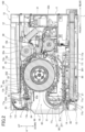
- FIG.2 is a cross-sectional view taken by a vertical plane passing the center in the width direction W of the printer 100 along a front-rear direction L.
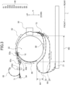
- FIG. 3 is a schematic view that is schematically shown by simplifying FIG. 2 for clarifying the transport path 80 shown in FIG. 2 .
- FIG. 4 is a perspective view showing the printer with a front top cover 13 of the printer 100 open and a roll paper storage 22 pulled forward in the front-rear direction L.
- FIG. 5 is a front view of the printer in the condition of FIG. 4 seen from the front.
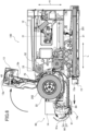
- FIG. 6 is a sectional view of the printer in the condition of FIG. 4 , which is corresponding to FIG. 2 .
- the printer shown in the drawings is the printer in one embodiment of the present invention.
- the printer 100 includes a case 10, a sheet paper storage 21, a roll paper storage 22, a printing portion 30, a cutter 40, a transport portion 70, and a transport path 80.
- a top cover 12 is disposed to close a top opening in a height direction H of a case body 11.
- the top cover 12 is formed with a recess at the front-end portion and the inner portion 12a, excluding both side edges and the rear edge of the outer periphery to function as a stacker to receive a sheet paper 201 (hereinafter, also simply referred to as paper 201) or an unwound paper 203 from a roll paper 202 (hereinafter, also simply referred to as paper 203) is stored.
- a bottom surface 12b of the recessed portion 12a of the top cover 12 is inclined so that the front side is lower than the rear side. Due to the inclination of the bottom surface 12b, the paper 201, 203 discharged rearward from an upper outlet 13b of the front top cover 13, which is described later, is stacked on the front side of the bottom surface 12b of the recessed portion 12a.
- the front top cover 13 is disposed at the top of the front surface of the printer 100.
- a front bottom cover 15 is disposed at the bottom of the front surface of the printer 100.
- a front center cover 14 is disposed between the front top cover 13 and the front bottom cover 15 on the front surface of the printer 100.
- the front top cover 13 and the front center cover 14 are provided in an internal drawer 60 (one example of a drawer unit).
- the internal drawer 60 is arranged within the inner part of the printer enclosed by the case body 11 and the top cover 12.
- the internal drawer 60 can be pulled forward relative to the case body 11 and the top cover 12 by pulling it forward in the front-rear direction L with a user's finger placed on a fingerhold 14a formed at the bottom of the front center cover 14.
- the internal drawer 60 includes the roll paper storage 22, the cutter 40, the transport portion 70, and the transport path 80.
- the front top cover 13 is supported to be rotatable in the upper rearward direction shown with the arrow in FIGS. 4 and 6 , in a condition that the internal drawer 60 has been drawn forward from the inner part enclosed by the case body 11 and the top cover 12 as shown in FIGS. 4 and 6 , from a condition that the front top cover 13 is closed as shown in FIG. 1 .
- the front top cover 13 is opened by the upper rearward rotation, the front and the top of the roll paper storage 22 are partially exposed. This exposes the roll paper storage 22 formed within the case 10, thereby enabling the roll paper 202 to be inserted into or removed from the roll paper storage 22.
- the trash box 16 cannot be removed from the front center cover 14 when the front top cover 13 is closed, but can be removed from the front center cover 14 when the front top cover 13 is opened.
- the cut-off pieces and/or other waste within the trash box 16 can be disposed of when the trash box 16 is removed from the front center cover 14.
- the sheet paper storage 21 is provided at the bottom of the printer 100 and below the roll paper storage 22.
- the sheet paper storage 21 stores a plurality of sheet paper 201 that has been cut into a predetermined size and stacked up in the thickness direction.
- the roll paper storage 22 is formed in the internal drawer 60.
- the roll paper storage 22 is configured to store the roll paper 202 prepared by rolling the elongated paper 203. As shown in FIGS. 2 , and 4 to 6 , the roll paper storage 22 holds the roll paper 202 in an orientation where the axis of the roll paper 202 is parallel to the width direction W of the printer 100.
- the ink ribbon 32 is provided in the internal drawer 60. As shown in FIGS. 4 and 6 , the ink ribbon 32 can be drawn forward passing through a region above the roll paper storage 22 in an arc shape when the internal drawer 60 is drawn to the front side from the case body 11 and the front top cover 13 is not rotated to the upper rear side.
- the platen roller 33 is disposed on the opposite side of the ink ribbon 32 and the thermal head 31 with the paper 201, 203 interposed therebetween.
- the platen roller 33 is configured to press the paper 201, 203 against the ink ribbon 32.
- the cutter 40 is disposed in the front top cover 13 on the front side of the roll paper storage 22. Under the control of the controller (not illustrated) of the printer 100, the cutter 40 cuts, along the width direction W, the paper 201, 203 passing through a portion (a joined path 83d described below) of the transport path 80 extending forward from the upper side of the roll paper storage 22. Cut pieces of the paper 201 fall into and are stored in the trash box 16 disposed below the cutter 40.
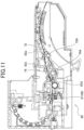
- FIGS. 7 to 11 are views for clarifying the transport-path switching mechanism that switches between the printing on the paper and the discharge of the paper and is covered with the front top cover 13.
- FIGS. 7 , 9 , and 11 are enlarged sectional views showing a part of FIG. 2 without the roll paper storage.
- FIGS. 8 and 10 are perspective views showing members that constitute the transport-path switching mechanism without other members for describing the operation of the transport-path switching mechanism.
- the transport-path switching mechanism 50 includes a first flap (printing discharge switching flap) 72, a second flap (de-curling switching flap) 74, a movable member 51, and a switching mechanism 52.
- the first flap (printing discharge switching flap) 72 is configured to switch the path of the paper 201, 203 to one of the first and second paths.
- the first path is a printing path (printing upstream path 86 described later) selected for printing on the paper 201, 203
- the second path is a traveling path (discharge path 83a described later) selected for moving the paper 201, 203 toward the outlet.
- the first flap 72 is configured to rotate about a rotation shaft 72A over a predetermined angular range.
- the first flap 72 includes a connecting portion 72B relating to the first link 53, which is described later, at one of the ends.
- the second flap (de-curling switching flap) 74 is provided downstream of the first flap (printing discharge switching flap) 72 in the transport direction to switch the path of the paper 201, 203, which has been transported through the second path (discharge path 83a), to one of the third and fourth paths.
- the third path is a de-curling treatment discharge path 83b that is configured to discharge the paper after a de-curling treatment to correct the curl of the paper (particularly paper 203).
- the fourth path is a discharge path 83c that is configured to make the paper 201, 203, which has passed through the second path (discharge path 83a), travel directly toward the outlet.
- the de-curling treatment discharge path 83b and the discharge path 83c join together on a downstream side to form the joined path 83d.
- the second flap 74 is configured to rotate about a rotation shaft 74A over a predetermined angular range.
- the second flap 74 includes, at one of the ends, a connecting portion 74B relating to the second link 54 which is described later.
- the movable member 51 is configured to move in the width direction W of the paper 201, 203, which is orthogonal to the transport direction.
- the cutter 40 also functions as the movable member 51.
- the switching mechanism 52 switches the first flap 72 between a state in which the movable member 51 is disposed at a first position P1 and a state in which the movable member 51 is disposed at a position other than the first position P1.
- the switching mechanism 52 also switches the second flap 74 between a state in which the movable member is disposed at a second position P2 and a state in which the movable member 51 is disposed at a position other than the second position P2.
- the switching mechanism 52 includes the first link 53 and the second link 54.
- the first link 53 is configured to switch the first flap 72 between a state in which the movable member 51 is disposed at a first one (first position) P1 in the width direction W and a state in which the movable member 51 is disposed at a position other than the first end.
- the second link 54 is configured to switch the second flap 74 between a state in which the movable member 51 is disposed at a second end (second position) P2 in the width direction W and a state in which the movable member 51 is disposed at a position other than the second end.
- the first link 53 includes a rotation shaft portion 53A, a movable member contact portion 53B, and a plate spring attachment portion 53C.
- the rotation shaft portion 53A is configured to rotate about a rotation axis, which is partially shown in the drawings.
- the movable member contact portion 53B is configured to contact the movable member 51 when the movable member 51 is positioned at the first end P1.
- a plate spring (elastic member) 53D is attached to the plate spring attachment portion 53C.
- the plate spring (elastic member) 53D is in contact with the connecting portion 72B of the first flap 72.
- the first flap 72 and the first link 53 are connected via the plate spring 53D.
- the first flap 72 allows the paper 201, 203 to pass through the second path even if the path is switched to the first path.
- the first flap 72 is switched to the first path as shown in FIG. 11 .
- the first flap 72 presses on the passing paper 201, 203 via the plate spring 53D with a spring force to allow the paper 201, 203 to continuously pass through the second path (the first flap 72, which rotates in a direction to prevent the paper from passing through the second path, is provided with a rotational force to contact the paper while allowing the paper to pass through the second path). If the first flap 72 has been switched to the first path before the paper passes through the second path, the paper will pass through the first path because the first flap 72 closes the second path. In this way, the single movable member 51 can switch the four paths, i.e., the first to fourth paths.
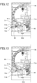
- FIGS. 12 and 13 are enlarged sectional views showing a part of FIG. 2 for clarifying a discharge path switching mechanism.
- the printer includes the front outlet 13a which is the first outlet to discharge the paper 201, 203, and the upper outlet 13b which is the second outlet to discharge the paper 201, 203.
- the second outlet is different from the first outlet.
- the printer also includes a discharge path switching member 71 that switches the passages between the first discharge passage (front discharge path 84 described later), which communicates with the front outlet 13a, and the second discharge passage (upper discharge path 85 described later), which communicates with the upper outlet 13b to connect the transport passage (joined path 83d) with the first discharge passage or the second discharge passage.
- the discharge path switching member 71 when the discharge path switching member 71 is at a first position P11 where the first discharge passage (front discharge path 84) is not blocked, the transport passage (joined path 83d) and the first discharge passage (front discharge path 84) are connected. Upon this, when a bottom wall 71B of the discharge path switching member is at the first position P11, it constitutes a part of the first discharge passage (front discharge path 84).
- an inner wall 71A of the discharge path switching member 71 constitutes a part of a connecting passage that connects the transport passage (joined path 83d) and the second discharge passage (upper discharge path 85).
- the inner wall 71A of the discharge path switching member 71 is curved such that, when an end of the paper 201, 203 comes into contact therewith, the paper 201, 203 transported through the transport passage (joined path 83d) in the front-rear direction L is guided in an upward direction L and smoothly discharged from the upper outlet 13b.
- the first position P11 and the second position P12 are aligned in the vertical direction H of the printer 100.
- the discharge path switching member 71 includes an extended wall 71C that projects toward the front surface side of the printer 100 and that extends continuously to be flush with the bottom wall 71B.
- a user pinches the extended wall 71C to move the discharge path switching member 71 between the first position P11 and the second position P12.
- the discharge path switching member 71 may be provided on a surface of the printer 100 other than the front surface, for example, on a side surface in a projecting manner.
- the transport path 80 is a path for transporting the paper 201, 203. First, a portion of the transport path 80 for transporting the sheet paper 201 is described.
- the part of the transport path 80 where the sheet paper 201 is transported includes a feeding path 81, the printing path 82, the discharge path 83a, the de-curling treatment discharge path 83b, the discharge path 83c, the joined path 83d, the front discharge path 84, the upper discharge path 85, the printing upstream path 86, and a printing downstream path 87.
- the feeding path 81 extends upward from the front end of the sheet paper storage 21, then extends to turn back rearward and downward in a space formed in front of the roll paper storage 22 and behind the front center cover 14. Then, the feeding path 81 extends below the roll paper storage 22 and above the sheet paper storage 21 toward the rear of the roll paper storage 22 and then extends to an upwardly raised position at the rear of the roll paper storage 22.
- the printing path 82 extends upward at the rear of the roll paper storage 22 along the rear of the roll paper storage 22. Then, the printing path 82 extends forward and above the roll paper storage 22 to the front part above the roll paper storage 22.
- the printing portion 30 is disposed at the printing path 82.
- the discharge path 83a extends forward from the front part above the roll paper storage 22 along the front-rear direction L.
- the discharge path 83a is separated into the de-curling treatment discharge path 83b and the discharge path 83c by the de-curling switching flap (second flap) 74.
- the de-curling treatment discharge path 83b and the discharge path 83c join together on a downstream side to form the joined path 83d.
- the cutter 40 is disposed at the joined path 83d.
- the joined path 83d extends to a position that is forward of the cutter 40.
- the front discharge path 84 extends forward to the front outlet 13a.
- the upper discharge path 85 extends upward and rearward in a curved manner.
- the printing upstream path 86 extends from the front part above the roll paper storage 22 toward below the roll paper storage 22 to a position just before reaching the feeding path 81.
- the printing upstream path 86 extends concentrically with the outer periphery of the roll paper storage 22.
- the printing discharge switching flap (first flap) 72 is provided.
- the printing discharge switching flap 72 is rotatably provided so that its tip is displaced upward or downward and rotates by the control of the controller of the printer 100 not shown in the drawings. In a condition shown in FIG. 2 , the printing discharge switching flap 72 is in a condition where the tip is displaced downwardly within its displaceable range.
- the paper 201 that has traveled forward in the printing path 82 is switched to travel to the discharge path 83.
- the paper 201 that has traveled forward in the printing path 82 is switched to travel to the printing upstream path 86.
- the printing downstream path 87 follows the end of the printing path 82 on the side of the feeding path 81.
- the printing downstream path 87 extends from the rear to the front of the roll paper storage 22 below the roll paper storage 22 and the feeding path 81 and above the sheet paper storage 21.
- a tip on the front side of the printing downstream path 87 rises upwardly and is formed to smoothly join the feeding path 81 similarly rising upwardly.
- a reversing portion 90 that reverses the front and back sides of the paper 201 is described.
- the paper 201 is printed on its surface with which the ink ribbon 32 comes into contact in the printing path 82, that is, on its surface facing rearward in the front-rear direction L in FIGS. 2 and 3 .
- the surface printed in the printing path 82 faces downward in the height direction H when the paper 201 is transported to the printing downstream path 87.
- the paper 201 is transported forward in the printing downstream path 87 and then in the feeding path 81 rising upward.
- the printed surface of the paper 201 faces upward in the height direction H below the roll paper storage 22 when the paper 201 is transported in the feeding path 81.
- the paper 201 is transported rearward in the feeding path 81 and then in the printing path 82 rising upward.
- the printed surface of the paper 201 faces forward in the front-rear direction when the paper 201 is transported in the printing path 82.
- the paper 201 is turned over while transported in the feeding path 81 from the printing downstream path 87, and as a result, the front and back sides of the paper 201 are reversed. Therefore, the printing downstream path 87 and the feeding path 81 constitute the reversing portion 90 which reverses the front and back sides of the paper 201.
- the reversing portion 90 is a part of the transport path 80, and accordingly, it is provided in the internal drawer 60, similar to other parts of the transport path 80.
- the feeding path 81 includes a curved portion M1 that is convex upward and corresponds to at least a part of the reversing portion 90.
- the curved portion M1 is a portion that reverses the transport direction of the sheet paper 201, which is transported in the feeding path 81, from upward to downward.
- the curved portion M1 is formed in front of the roll paper storage 22 and overlaps with the roll paper storage 22 when it is viewed from the front (front in the front-rear direction L) of the printer 100 in the front-rear direction L.
- the curved portion M1 is formed, for example, to have a radius of curvature of 30 [mm].
- the curved portion M1 has a radius of curvature of 30 [mm] or greater.
- the radius of curvature of the curved portion M1 is not limited to 30 [mm] or greater.
- the radius of curvature of the curved portion M1 may be set at less than 30 [mm] depending on the thickness, property, etc. of the paper 201, 203 to be used.
- Some sheet paper 201 is hardly impaired by the curved portion M1 in terms of the transport smoothness, depending on the thickness or property of the paper.
- the sheet paper 201 which is hardly impaired in terms of the transport smoothness, can be selected and used as long as the radius of curvature of the curved portion M1 is 20 [mm] or greater.
- a portion M2 of the feeding path 81 and the printing downstream path 87 passes below the roll paper storage 22 and corresponds to at least another part of the reversing portion 90.
- the portion M2 is formed below the roll paper storage 22 and overlaps with the roll paper storage 22 when it is viewed downward in the height direction H from above.
- the reversing portion 90 does not overlap at all with the roll paper storage 22 when it is viewed from one side to the other side of the printer 100 in the width direction W.
- the part of the transport path 80 for transporting the paper 203 unwound from the roll paper 202 is described.
- the part of the transport path 80 includes a roll paper feeding path 89 as shown by a single-point chain line in FIGS. 2 and 3 .
- the roll paper feeding path 89 extends rearward from substantially the bottom of the roll paper 202 stored in the roll paper storage 22 to an upwardly rising position at the rear of the roll paper storage 22.
- a feeding switching flap 73 is provided at a part where the feeding path 81 and the roll paper feeding path 89 join.
- the feeding switching flap 73 is rotatably provided so that its tip can be displaced forward or rearward. In a condition shown in FIG. 2 , the tip of the feeding switching flap 73 is biased toward the front side within its displaceable range by a spring not shown in the drawings.
- the paper 201 transported through the feeding path 81 is switched to travel to the printing path 82, and the paper 201 transported from the printing path 82 is switched to travel to the printing downstream path 87.
- the paper 203 unwound from the roll paper 202 is printed at the printing portion 30 of the printing path 82, the paper 203 remains unseparated from the roll paper 202. Therefore, the feeding switching flap 73 remains pressed toward the rear side in the displaceable range of the tip by a part of the paper 203 passing through the roll paper feeding path 89.
- the feeding switching flap 73 may also be rotated by the control of the controller (not shown in the drawings) of the printer 100.
- the transport portion 70 includes a sheet paper delivery roller 77a, a feeding roller 77b, a reversing roller 77c, a gripping roller 77d, a first sending roller 77e, a first discharge roller 77f, a second discharge roller 77g, and a roll paper delivery roller 77i.
- Each of these transport rollers 77a to 77i contacts the front or back surface of at least one of the sheet paper 201 or the paper 203, and rotates by the control of the controller (not shown in the drawings) of the printer 100, thereby transporting the paper 201, 203 along the transport path 80.
- the sheet paper delivery roller 77a is disposed above the vicinity of the front end of the sheet paper storage 21.
- the sheet paper delivery roller 77a contacts the uppermost sheet paper 201 among the paper 201 stored in the sheet paper storage 21 and rotates to deliver the sheet paper 201 to the feeding path 81.
- the sheet paper delivery roller 77a can rotate in a direction opposite to the delivery direction so that the sheet paper 201 delivered to the feeding path 81 is pulled back into the sheet paper storage 21.
- the feeding roller 77b is disposed at a position of the feeding path 81 that is close to the sheet paper delivery roller 77a.
- the feeding roller 77b contacts the sheet paper 20 delivered to the feeding path 81 by the sheet paper delivery roller 77a and transports the sheet paper 201 upward along the feeding path 81.
- the feeding roller 77b can also rotate in a direction opposite to the transport direction, thereby pulling the sheet paper 201 back.
- the reversing roller 77c, the gripping roller 77d, the first sending roller 77e, the first discharge roller 77f, the second discharge roller 77g, and a second sending roller 77h, which are described later, can also rotate in directions opposite to their transport directions, similar to the feeding roller 77b, thereby pulling the sheet paper 201 back.
- the reversing roller 77c is disposed in a part of the feeding path 81 above the feeding roller 77b.
- the reversing roller 77c contacts the sheet paper 201 traveled in the feeding path 81 by the feeding roller 77b and transports the sheet paper 201 along the feeding path toward the printing path 82.
- the gripping roller 77d is disposed in a part of the printing path 82 that is on the side closer to the feeding path 81 and at a position ahead of the tip of the feeding switching flap 73.
- the gripping roller 77d contacts the sheet paper 201 transported to the printing path 82 and transports the sheet paper 201 through the printing portion 30 toward the discharge path 83a or the printing upstream path 86.
- the feeding switching flap 73 is switched forward, thereby allowing the sheet paper 201 transported through the feeding path to be transported to the printing path 82.
- the first sending roller 77e is disposed in a part of the joined path 83d closer to the printing path 82 than the cutter 40.
- the first sending roller 77e contacts the sheet paper 201 transported to the joined path 83d and transports the sheet paper 201 to the first discharge roller 77f through the cutter 40.
- the first discharge roller 77f is disposed near the end of the joined path 83d that is on the side farther from the printing path 82 and at a position before the discharge path switching member 71.
- the first discharge roller 77f contacts the sheet paper 201 transported to the joined path 83d and transports the sheet paper 201 to the front discharge path 84 or the upper discharge path 85 depending on the position of the discharge path switching member 71.
- the second discharge roller 77g is disposed near the upper outlet 13b of the upper discharge path 85.
- the second discharge roller 77g contacts the sheet paper 201 transported to the upper discharge path 85 and discharges the sheet paper 201 from the upper outlet 13b into the recessed portion 12a which functions as a stacker of the top cover 12.
- the roll paper delivery roller 77i is disposed in a part of the roll paper feeding path 89 on the side closer to the printing path 82 and at a position ahead of the tip of the feeding switching flap 73.
- the roll paper delivery roller 77i contacts the paper 203 wound around the outermost circumference of the roll paper 202 stored in the roll paper storage 22 and rotates to deliver the paper 203 toward the gripping roller 77d.
- the roll paper delivery roller 77i also can rotate in a direction opposite to the delivery direction so that the paper 203 delivered toward the gripping roller 77d is rewound around the roll paper 202 of the roll paper storage 22.
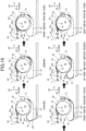
- FIGS. 14 , 15 , and 16 are simplified sectional views corresponding to FIG. 3 , schematically showing the movement of the sheet paper 201 when the printer 100 conducts printing on both the front and back surfaces of the sheet paper 201.
- FIG. 17 is a simplified sectional view corresponding to FIG. 3 , schematically showing the movement of the paper 203 when the printer 100 conducts printing on the roll paper 202.
- the sheet paper delivery roller 77a (see FIG. 2 , the same applies hereinafter) rotates to deliver the uppermost sheet paper 201 from the stack of the sheet paper 201 stored in the sheet paper storage 21. Further, as shown in the upper left of FIG. 14 , the rotations of the feeding roller 77b and the reversing roller 77c transport the sheet paper 201 in the feeding path 81 in the directions shown with the arrows.
- the sheet paper 201 is guided to the printing path 82 by switching the feeding switching flap 73 and travels in the printing path 82 by the rotation of the gripping roller 77d. Then, as shown in the upper right of FIG.14 , the sheet paper 201 is guided to the printing upstream path (first path) 86 by switching the printing discharge switching flap (first flap) 72.
- the gripping roller 77d reverses (its rotational direction becomes opposite) and passes through the printing portion 30. As shown in the lower left of FIG.14 , the sheet paper 201 is printed on the front surface while passing through the printing portion 30 and moves to the printing downstream path 87.
- the sheet paper 201 is transported to the feeding path 81 by the rotation of the reversing roller 77c and the front and back surfaces of the sheet paper 201 are reversed by passing the reversing portion 90, which consists of the printing downstream path 87 and the feeding path 81.
- the sheet paper 201 is turned over when passing through the reversing portion 90, and the surface to be printed by the printing portion 30 in the printing path 82 is reversed.
- the sheet paper 201 reversed by the reversing portion 90 is transported to the end of the printing upstream path 86 by the rotation of the gripping roller 77d which has been reversed again.
- the gripping roller 77d reverses again. Accordingly, as shown in the upper left of FIG. 15 , the sheet paper 201 passes through the printing portion 30 and travels to the printing downstream path 87 while being printed on the back surface of the sheet paper 201.
- the gripping roller 77d is reversed again. Accordingly, the sheet paper 201 passes through the printing path 82 as shown in the upper center of FIG. 15 from the condition shown in the upper left of FIG. 15 . Then, the cutter 40 (movable member 51) moves to the first position P1, and the printing discharge switching flap (first flap) 72 is switched to transport the sheet paper 201 to the discharge path (second path) 83a.
- the cutter 40 moves to the second position P2, and the de-curling switching flap (second flap) 74 is switched so that the sheet paper 201 is transported to the joined path 83d via the discharge path (fourth path) 83c in the condition of FIG. 11 .
- the sheet paper 201 travels to the cutter 40 by the rotation of the first sending roller 77e, and the unnecessary part at the rear end of the sheet paper 201 is cut by the cutter 40 in the condition shown by the upper right of FIG. 15 .
- the cut-off unnecessary part falls into the trash box 16 (see FIG. 2 ), which is disposed below the cutter 40, and is stored in the trash box 16.
- the sheet paper 201 whose unnecessary rear-end part has been cut off is transported toward the printing path 82 through the joined path 83d, the discharge path 83c, and the discharge path 83a by the reversal of the first sending roller 77e. Further, the gripping roller 77d reverses again, and accordingly, the sheet paper 201 passes through the printing path 82 and is pulled back to the printing downstream path 87 as shown in the lower left of the same drawing.
- the sheet paper 201 is transported to the printing path 82 by passing through the reversing portion 90 which consists of the printing downstream path 87 and the feeding path 81.
- the gripping roller 77d reverses again, thereby transporting the sheet paper 201 to the discharge path 83 as shown in the upper left of FIG. 9 .
- the sheet paper 201 is transported to the cutter 40 by the rotation of the first sending roller 77e in the discharge path 83.
- the unnecessary part at the front end of the sheet paper 201 is cut off by the cutter 40.
- the cut-off unnecessary part falls into the trash box 16 (see FIG. 2 ), which is disposed below the cutter 40, and is stored inside the trash box 16.
- the sheet paper 201 whose unnecessary front end part has been cut off passes through the cutter 40 and travels forward by the rotation of the first sending roller 77e.
- the sheet paper 201 traveled ahead of the cutter 40 is transported by the rotation of the first discharge roller 77f.
- the sheet paper is guided to the upper discharge path 85, and, as shown in the upper right of the same drawing, the sheet paper 201 is discharged from the upper outlet 13b by the rotation of the second discharge roller 77g which is located close to the upper outlet 13b.
- the sheet paper 201 is guided to the front discharge path 84, and, as shown in the lower right of the same drawing, the sheet paper 201 is discharged from the front outlet 13a.
- the roll paper delivery roller 77i (see FIG. 2 , the same applies hereinafter) rotates, and the rotation of the roll paper delivery roller 77i unwinds the paper 203 from the outermost circumference of the roll paper 202 stored in the roll paper storage 22.
- the unwound paper 203 is transported in the printing path 82 and the printing upstream path (first path) 86 by switching the feeding switching flap 73 to the rear side and the printing discharge switching flap 72 to the upper side as well as by rotating the roll paper delivery roller 77i and the gripping roller 77d, and the unwound paper 203 is delivered by a length necessary for the printing as shown in the upper center of FIG. 17 .
- the delivered paper 203 is pulled back to the printing path 82 and the roll paper feeding path 89 by reversing the gripping roller 77d and the roll paper delivery roller 77i.
- the printing portion 30 prints on the paper 203 while the paper 203 passes through the printing path 82.
- the cutter 40 (movable member 51) stays at the first position P1, and the roll paper 203 is transported to the joined path 83d through the de-curling treatment discharge path (third path) 83b.
- the paper 203 passes the cutter 40 by the rotation of the second sending roller 77e.
- the cutter 40 cuts the unnecessary part at the front end in the transport direction of the paper 203 if necessary.
- the cut-off unnecessary part of the paper 203 is stored in the trash box 16.
- the printed paper 203 whose unnecessary part has been cut off is transported to the front outlet 13a through the front discharge path 84 by the switch of the discharge path switching member 71 to the upper side at the separation point and the rotation of the first discharge roller 77f.
- the cutter cuts the paper 203 to cut off the paper 203 including the printed region from the paper 203 connected to the roll paper 202.
- the paper 203 on the side connected to the roll paper 202 is rewound around the roll paper 202 by reversing the second sending roller 77e, the gripping roller 77d, and the roll paper feeding roller 77i.
- the paper 203 including the printed region and separated from the roll paper 202 is discharged from the front outlet 13a, as shown in the lower right of the same drawing.
- the printed paper 203 may be discharged from the upper outlet 13b through the upper discharge path 85 by switching the discharge path switching member 71 to the lower side at the separation point.
- the printer 100 of the present embodiment can switch the first flap and the second flap as well as the four paths in which the paper travels with the single movable member 51. Further, the cutter 40 provided in the printer for cutting the paper also functions as the movable member 51, thereby reducing the number of components.
- the first flap 72 allows the paper to pass through the second path although the path is switched to the first path. In this way, it is possible to switch the paths with the single movable member 51 even if the paper passes over both the first flap 72 and the second flap 74.
- the printer 100 of the present embodiment is a dye-sublimation thermal printer, but the printer according to the present invention is not limited to the dye-sublimation thermal printer. It may be another printing-type printer other than the dye-sublimation thermal printer.
- the printer 100 of the present embodiment has shown an exemplary to include the switching mechanism that switches the two flaps of the first flap and the second flap.
- the printer according to the present invention can also have a configuration to perform switching three or more flaps with a single movable member.
- the printer according to the present invention can have a configuration to perform switching a plurality of flaps by a movable member.
- the second flap functions as the de-curling switching flap, but it may perform switching between other paths (for example, between the printing path and the discharge path, and/or between the front discharge path and the upper discharge path).
- the first and second positions in the width direction are not limited to the left and right ends in the width direction of the paper, but may be arranged side by side at one of the ends or may not be at the end or ends in the width direction of the paper as long as it does not affect the paper cutting operation.
Landscapes
- Engineering & Computer Science (AREA)
- Mechanical Engineering (AREA)
- Separation, Sorting, Adjustment, Or Bending Of Sheets To Be Conveyed (AREA)
- Handling Of Sheets (AREA)
Abstract
Description
- The present invention relates to a printer.
- A printer is required to switch paper transport paths within the printer when printing or discharging paper. At a point where the paper transport paths are switched, it is necessary to have a flap that switches the transport paths and a drive mechanism that drives and moves the flap by a command from a controller (e.g.,
Patent Literature 1, Patent Literature 2, etc.). -
- Patent Literature 1:
JP 2021-160899A - Patent Literature 2:
JP 2015-189204A - Adding a flap and its corresponding drive mechanism at each point where the paper transport paths are switched increases the number of components, thereby also increasing the production cost.
- An object of the present invention is to provide a printer that moves flaps by a drive mechanism whose number is less than that of the flaps, thereby reducing the number of components for driving the flaps.
- To achieve the object, a printer includes a first flap that is configured to switch a path for a paper transported in a transport direction, to one of a first path and a second path; a second flap that is provided downstream of the first flap in the transport direction and configured to switch the path for the paper transported through the first path, to one of a third path and a fourth path; a movable member that is configured to move in a width direction of the paper, the width direction being orthogonal to the transport direction; and a switching mechanism that is configured to switch the first flap between a state in which the movable member is disposed at a first position in the width direction and a state in which the movable member is disposed at a position other than the first position in the width direction, and to switch the second flap between a state in which the movable member is disposed at a second position in the width direction and a state in which the movable member is disposed at a position other than the second position in the width direction.
- This configuration allows a single movable member to switch the first and second flaps and the four paths through which the paper travels.
-
- [
FIG. 1] FIG. 1 is a perspective view showing an external appearance of a dye-sublimation thermal printer (hereinafter referred to as printer). - [
FIG. 2] FIG.2 is a cross-sectional view taken by a vertical plane passing the center in the width direction W of the printer along a front-rear direction L. - [
FIG. 3] FIG. 3 is a schematic view schematically showing a transport path by simplifyingFIG. 2 , for clarifying the transport path shown inFIG. 2 . - [
FIG. 4] FIG. 4 is a perspective view showing the printer with a front upper cover open and a roll paper storage pulled forward in the front-rear direction L. - [
FIG. 5] FIG. 5 is a front view of the printer in the condition ofFIG. 4 seen from the front. - [
FIG. 6] FIG. 6 is a sectional view of the printer in the condition ofFIG. 4 , corresponding toFIG. 2 . - [
FIG. 7] FIG. 7 is an enlarged sectional view showing a part ofFIG. 2 without the roll paper storage. - [
FIG. 8] FIG. 8 is a perspective view showing members that constitute a transport-path switching mechanism without other members. - [
FIG. 9] FIG. 9 is an enlarged sectional view showing a part ofFIG. 2 without the roll paper storage. - [
FIG. 10] FIG. 10 is a perspective view showing members that constitute a transport-path switching mechanism without other members. - [
FIG. 11] FIG. 11 is an enlarged sectional view showing a part ofFIG. 2 without the roll paper storage. - [
FIG. 12] FIG. 12 is an enlarged sectional view showing a part ofFIG. 2 for clarifying a discharge path switching mechanism section and showing a condition where a discharge path switching member is at a first position. - [
FIG. 13] FIG. 13 is an enlarged sectional view showing a part ofFIG. 2 for clarifying a discharge path switching mechanism section and showing a condition where the discharge path switching member is at a second position. - [
FIG. 14] FIG. 14 is a simplified sectional view (No. 1) corresponding toFIG. 3 , schematically showing the movement of a sheet paper when the printer conducts a printing on both front and back surfaces of the sheet paper. - [
FIG. 15] FIG. 15 is a simplified sectional view (No. 2) corresponding toFIG. 3 , schematically showing the movement of the sheet paper when the printer conducts the printing on both front and back surfaces of the sheet paper. - [
FIG. 16] FIG. 16 is a simplified sectional view (No. 3) corresponding toFIG. 3 , schematically showing the movement of the sheet paper when the printer conducts the printing on both front and back surfaces of the sheet paper. - [
FIG. 17] FIG. 17 is a simplified sectional view corresponding toFIG. 3 , schematically showing the movement of a paper when the printer conducts printing on the roll paper. - In the following, embodiments of the printer according to the present invention is described with reference to the drawings.
- (Configuration)
FIG. 1 is a perspective view showing an external appearance of a dye-sublimation thermal printer 100 (hereinafter, referred to as printer 100).FIG.2 is a cross-sectional view taken by a vertical plane passing the center in the width direction W of theprinter 100 along a front-rear direction L.FIG. 3 is a schematic view that is schematically shown by simplifyingFIG. 2 for clarifying thetransport path 80 shown inFIG. 2 .FIG. 4 is a perspective view showing the printer with afront top cover 13 of theprinter 100 open and aroll paper storage 22 pulled forward in the front-rear direction L.FIG. 5 is a front view of the printer in the condition ofFIG. 4 seen from the front.FIG. 6 is a sectional view of the printer in the condition ofFIG. 4 , which is corresponding toFIG. 2 . - The printer shown in the drawings is the printer in one embodiment of the present invention. The
printer 100 includes acase 10, asheet paper storage 21, aroll paper storage 22, aprinting portion 30, acutter 40, atransport portion 70, and atransport path 80. - A
top cover 12 is disposed to close a top opening in a height direction H of acase body 11. Thetop cover 12 is formed with a recess at the front-end portion and theinner portion 12a, excluding both side edges and the rear edge of the outer periphery to function as a stacker to receive a sheet paper 201 (hereinafter, also simply referred to as paper 201) or anunwound paper 203 from a roll paper 202 (hereinafter, also simply referred to as paper 203) is stored. - As shown in
FIG. 2 , abottom surface 12b of therecessed portion 12a of thetop cover 12 is inclined so that the front side is lower than the rear side. Due to the inclination of thebottom surface 12b, thepaper upper outlet 13b of thefront top cover 13, which is described later, is stacked on the front side of thebottom surface 12b of therecessed portion 12a. - The
front top cover 13 is disposed at the top of the front surface of theprinter 100. Afront bottom cover 15 is disposed at the bottom of the front surface of theprinter 100. Afront center cover 14 is disposed between thefront top cover 13 and thefront bottom cover 15 on the front surface of theprinter 100. - (Internal Drawer Unit) As shown in
FIGS. 4 and6 , thefront top cover 13 and thefront center cover 14 are provided in an internal drawer 60 (one example of a drawer unit). Theinternal drawer 60 is arranged within the inner part of the printer enclosed by thecase body 11 and thetop cover 12. Theinternal drawer 60 can be pulled forward relative to thecase body 11 and thetop cover 12 by pulling it forward in the front-rear direction L with a user's finger placed on afingerhold 14a formed at the bottom of thefront center cover 14. - In addition to the
front top cover 13 and thefront center cover 14, theinternal drawer 60 includes theroll paper storage 22, thecutter 40, thetransport portion 70, and thetransport path 80. - The
front top cover 13 is supported to be rotatable in the upper rearward direction shown with the arrow inFIGS. 4 and6 , in a condition that theinternal drawer 60 has been drawn forward from the inner part enclosed by thecase body 11 and thetop cover 12 as shown inFIGS. 4 and6 , from a condition that thefront top cover 13 is closed as shown inFIG. 1 . When thefront top cover 13 is opened by the upper rearward rotation, the front and the top of theroll paper storage 22 are partially exposed. This exposes theroll paper storage 22 formed within thecase 10, thereby enabling theroll paper 202 to be inserted into or removed from theroll paper storage 22. - The
front top cover 13 includes afront outlet 13a on the front surface. Thefront outlet 13a is configured to discharge the printedpaper front top cover 13 further includes anupper outlet 13b on the rear surface. Theupper outlet 13b is configured to discharge the printedpaper top cover 12 and located at the rear of theupper outlet 13b. -
FIGS. 4 ,5 , and6 show theprinter 100 with a trash box 16 (seeFIGS. 1 and2 ) removed from thefront center cover 14. Thetrash box 16 is attached to thefront center cover 14 and positioned below thecutter 40, which is described later. Thetrash box 16 is a member to receive cut-off pieces generated when thecutter 40 cuts thepaper trash box 16 is attached to thefront center cover 14 and can be removed by sliding it upward relative to thefront center cover 14. - Therefore, the
trash box 16 cannot be removed from thefront center cover 14 when thefront top cover 13 is closed, but can be removed from thefront center cover 14 when thefront top cover 13 is opened. The cut-off pieces and/or other waste within thetrash box 16 can be disposed of when thetrash box 16 is removed from thefront center cover 14. - As shown in
FIGS. 2 and6 , thefront bottom cover 15 is formed on the front side of thesheet paper storage 21, which is shaped like a tray (thefront bottom cover 15 is a part of the sheet paper storage 21). - (Sheet paper storage) As shown in
FIG. 2 , thesheet paper storage 21 is provided at the bottom of theprinter 100 and below theroll paper storage 22. Thesheet paper storage 21 stores a plurality ofsheet paper 201 that has been cut into a predetermined size and stacked up in the thickness direction. - The
sheet paper storage 21 can be pulled or drawn forward relative to thecase body 11 and thetop cover 12 independently of theinternal drawer 60, by pulling thesheet paper storage 21 forward in the front-rear direction L with a user's fingers placed on afingerhold 15a formed on an upper part of thefront bottom cover 15. Thesheet paper storage 21 is opened at its top when it is drawn forward relative to thecase body 11 and thetop cover 12, which allows thesheet paper 201 to be inserted into or removed from thesheet paper storage 21 through the open top. - (Roll paper storage) As mentioned above, the
roll paper storage 22 is formed in theinternal drawer 60. Theroll paper storage 22 is configured to store theroll paper 202 prepared by rolling theelongated paper 203. As shown inFIGS. 2 , and4 to 6 , theroll paper storage 22 holds theroll paper 202 in an orientation where the axis of theroll paper 202 is parallel to the width direction W of theprinter 100. - The
roll paper storage 22 is located above thesheet paper storage 21 when theinternal drawer 60 is stored within thecase 10 as shown inFIG. 2 . InFIG. 2 , theroll paper 202 is positioned to rotate in a counterclockwise direction when thepaper 203 is drawn and unwound from the lower end of theroll paper 202 toward the right in the drawing. - (Printing Portion) The
printing portion 30 is disposed on the rear side of theroll paper storage 22. Under the control of a controller (not illustrated) of theprinter 100, theprinting portion 30 is configured to perform printing on thepaper printing path 82 described below) of thetransport path 80 rising substantially in the vertical direction on the rear side theroll paper storage 22. - The
printing portion 30 includes athermal head 31, theink ribbon 32, and theplaten roller 33. A sublimation dye is applied to a ribbon of theink ribbon 32. Theink ribbon 32 is fed from a feedingside roll 32a to a windingside roll 32b in synchronization with the transport of thepaper ink ribbon 32 is diffusively transferred to thepaper thermal head 31 contacting theink ribbon 32. Thereby, the printing is performed on thepaper - The
ink ribbon 32 is provided in theinternal drawer 60. As shown inFIGS. 4 and6 , theink ribbon 32 can be drawn forward passing through a region above theroll paper storage 22 in an arc shape when theinternal drawer 60 is drawn to the front side from thecase body 11 and the fronttop cover 13 is not rotated to the upper rear side. - As a result, the
ink ribbon 32 can be removed upward from the open upper side of theinternal drawer 60 between thetop cover 12 and the fronttop cover 13, which facilitates the replacement of theink ribbon 32. - The
platen roller 33 is disposed on the opposite side of theink ribbon 32 and thethermal head 31 with thepaper platen roller 33 is configured to press thepaper ink ribbon 32. - (Cutter) The
cutter 40 is disposed in the fronttop cover 13 on the front side of theroll paper storage 22. Under the control of the controller (not illustrated) of theprinter 100, thecutter 40 cuts, along the width direction W, thepaper path 83d described below) of thetransport path 80 extending forward from the upper side of theroll paper storage 22. Cut pieces of thepaper 201 fall into and are stored in thetrash box 16 disposed below thecutter 40. - (Transport-path Switching Mechanism)
FIGS. 7 to 11 are views for clarifying the transport-path switching mechanism that switches between the printing on the paper and the discharge of the paper and is covered with the fronttop cover 13.FIGS. 7 ,9 , and11 are enlarged sectional views showing a part ofFIG. 2 without the roll paper storage.FIGS. 8 and10 are perspective views showing members that constitute the transport-path switching mechanism without other members for describing the operation of the transport-path switching mechanism. - The transport-
path switching mechanism 50 includes a first flap (printing discharge switching flap) 72, a second flap (de-curling switching flap) 74, amovable member 51, and aswitching mechanism 52. - The first flap (printing discharge switching flap) 72 is configured to switch the path of the
paper upstream path 86 described later) selected for printing on thepaper path 83a described later) selected for moving thepaper first flap 72 is configured to rotate about arotation shaft 72A over a predetermined angular range. Thefirst flap 72 includes a connectingportion 72B relating to thefirst link 53, which is described later, at one of the ends. - The second flap (de-curling switching flap) 74 is provided downstream of the first flap (printing discharge switching flap) 72 in the transport direction to switch the path of the
paper path 83a), to one of the third and fourth paths. Specifically, in the present embodiment, the third path is a de-curlingtreatment discharge path 83b that is configured to discharge the paper after a de-curling treatment to correct the curl of the paper (particularly paper 203). The fourth path is adischarge path 83c that is configured to make thepaper path 83a), travel directly toward the outlet. The de-curlingtreatment discharge path 83b and thedischarge path 83c join together on a downstream side to form the joinedpath 83d. Thesecond flap 74 is configured to rotate about arotation shaft 74A over a predetermined angular range. Thesecond flap 74 includes, at one of the ends, a connectingportion 74B relating to thesecond link 54 which is described later. - The
movable member 51 is configured to move in the width direction W of thepaper cutter 40 also functions as themovable member 51. - The
switching mechanism 52 switches thefirst flap 72 between a state in which themovable member 51 is disposed at a first position P1 and a state in which themovable member 51 is disposed at a position other than the first position P1. Theswitching mechanism 52 also switches thesecond flap 74 between a state in which the movable member is disposed at a second position P2 and a state in which themovable member 51 is disposed at a position other than the second position P2. In the present embodiment, specifically, theswitching mechanism 52 includes thefirst link 53 and thesecond link 54. Thefirst link 53 is configured to switch thefirst flap 72 between a state in which themovable member 51 is disposed at a first one (first position) P1 in the width direction W and a state in which themovable member 51 is disposed at a position other than the first end. Thesecond link 54 is configured to switch thesecond flap 74 between a state in which themovable member 51 is disposed at a second end (second position) P2 in the width direction W and a state in which themovable member 51 is disposed at a position other than the second end. - The
first link 53 includes arotation shaft portion 53A, a movablemember contact portion 53B, and a platespring attachment portion 53C. Therotation shaft portion 53A is configured to rotate about a rotation axis, which is partially shown in the drawings. The movablemember contact portion 53B is configured to contact themovable member 51 when themovable member 51 is positioned at the first end P1. A plate spring (elastic member) 53D is attached to the platespring attachment portion 53C. The plate spring (elastic member) 53D is in contact with the connectingportion 72B of thefirst flap 72. Thus, thefirst flap 72 and thefirst link 53 are connected via theplate spring 53D. - As shown in
FIGS. 7 and8 , when themovable member 51 is positioned at a position other than the first position P1 (when themovable member 51 is at the second position P2 in this example), thefirst link 53 pushes up thefirst flap 72 via theplate spring 53D. In this condition, the path is switched to the first path by thefirst flap 72. As shown inFIGS. 9 and10 , when themovable member 51 moves and is disposed at the first position P1 at the first end, themovable member 51 is brought into contact with the movablemember contact portion 53B to push up the movablemember contact portion 53B, and thefirst link 53 rotates about therotation shaft portion 53A. Then, thefirst link 53 pushes down thefirst flap 72 via theplate spring 53D. Thus, the path is switched to the second path by thefirst flap 72. - The
second link 54 includes arotation shaft portion 54A, a movablemember contact portion 54B, and a platespring attachment portion 54C. Therotation shaft portion 54A is configured to rotate about a rotation axis, which is partially shown in the drawings. The movablemember contact portion 54B is configured to contact themovable member 51 when themovable member 51 is positioned at the second end P2. A plate spring (elastic member) 54D is attached to the platespring attachment portion 54C. The plate spring (elastic member) 54D is in contact with the connectingportion 74B of thesecond flap 74. Thus, thesecond flap 74 and thesecond link 54 are connected via theplate spring 54D. - As shown in
FIGS. 9 and10 , when themovable member 51 is positioned at a position other than the second position P2, thesecond link 54 pushes up thesecond flap 74 via theplate spring 54D. In this condition, the path is switched to the third path by thesecond flap 74. As shown inFIGS. 7 and8 , when themovable member 51 moves and is disposed at the second position P2 at the second end, themovable member 51 is brought into contact with the movablemember contact portion 54B to push up the movablemember contact portion 54B, and thesecond link 54 rotates about therotation shaft portion 54A. Then, thesecond link 54 pushes down thesecond flap 74 via theplate spring 54D. Thus, the path is switched to the fourth path by thesecond flap 74. - According to the present embodiment, in the condition that the
paper movable member 51 is at the first position P1), thefirst flap 72 allows thepaper FIGS. 9 and10 and themovable member 51 moves to the second position P2 to switch the third path to the fourth path by thesecond flap 74, thefirst flap 72 is switched to the first path as shown inFIG. 11 . However, in this condition, thefirst flap 72 presses on the passingpaper plate spring 53D with a spring force to allow thepaper first flap 72, which rotates in a direction to prevent the paper from passing through the second path, is provided with a rotational force to contact the paper while allowing the paper to pass through the second path). If thefirst flap 72 has been switched to the first path before the paper passes through the second path, the paper will pass through the first path because thefirst flap 72 closes the second path. In this way, the singlemovable member 51 can switch the four paths, i.e., the first to fourth paths. - (Discharge path switching mechanism)
FIGS. 12 and 13 are enlarged sectional views showing a part ofFIG. 2 for clarifying a discharge path switching mechanism. In the present embodiment, as mentioned above, the printer includes thefront outlet 13a which is the first outlet to discharge thepaper upper outlet 13b which is the second outlet to discharge thepaper path switching member 71 that switches the passages between the first discharge passage (front discharge path 84 described later), which communicates with thefront outlet 13a, and the second discharge passage (upper discharge path 85 described later), which communicates with theupper outlet 13b to connect the transport passage (joinedpath 83d) with the first discharge passage or the second discharge passage. - As shown in
FIG. 12 , when the dischargepath switching member 71 is at a first position P11 where the first discharge passage (front discharge path 84) is not blocked, the transport passage (joinedpath 83d) and the first discharge passage (front discharge path 84) are connected. Upon this, when abottom wall 71B of the discharge path switching member is at the first position P11, it constitutes a part of the first discharge passage (front discharge path 84). - As shown in
FIG. 13 , when the dischargepath switching member 71 is at a second position P12 where the first discharge passage (front discharge path 84) is blocked, aninner wall 71A of the dischargepath switching member 71 constitutes a part of a connecting passage that connects the transport passage (joinedpath 83d) and the second discharge passage (upper discharge path 85). Theinner wall 71A of the dischargepath switching member 71 is curved such that, when an end of thepaper paper path 83d) in the front-rear direction L is guided in an upward direction L and smoothly discharged from theupper outlet 13b. In the present embodiment, the first position P11 and the second position P12 are aligned in the vertical direction H of theprinter 100. - The discharge
path switching member 71 includes anextended wall 71C that projects toward the front surface side of theprinter 100 and that extends continuously to be flush with thebottom wall 71B. When switching the outlet of thepaper extended wall 71C to move the dischargepath switching member 71 between the first position P11 and the second position P12. The dischargepath switching member 71 may be provided on a surface of theprinter 100 other than the front surface, for example, on a side surface in a projecting manner. - The features and the advantageous effects of a printer including a discharge path switching mechanism are described.
- (1) A printer including a first outlet that is configured to discharge a paper; a second outlet that is configured to discharge the paper, wherein the second outlet is different from the first outlet; and a discharge path switching member that is configured to switch a transport passage for transporting the paper to one of a first discharge passage communicating with the first outlet, and a second discharge passage communicating with the second outlet to connect the transport passage with one of the first and second discharge passages. When the discharge path switching member is at a first position where the first discharge passage is not blocked, the transport passage and the first discharge passage are connected. When the discharge path switching member is at a second position where the first discharge passage is blocked, an inner wall of the discharge path switching member constitutes a part of a connecting passage that connects the transport passage and the second discharge passage.
Therefore, the discharge path switching member can switch between the first and second discharge passages. The discharge path switching member constitutes a part of the connecting passage. Accordingly, it is not necessary to separately prepare a component that constitutes the passage, thereby reducing the number of components. - (2) In the printer according to (1), the first outlet is a front outlet that is configured to discharge the paper to the front surface side. The second outlet is an upper outlet that is provided above the first outlet and configured to discharge the paper to an upper side. The discharge path switching member is movable between the first position and the second position.
Therefore, a simple operation of moving the discharge path switching member upward or downward makes it possible to switch the paper discharging outlet between the front outlet and the upper outlet. - (3) In the printer according to (2), the inner wall of the discharge path switching member has a curved shape to guide the paper, which has been transported through the transport passage in the front-rear direction orthogonal to the vertical direction, in an upward direction when an end of the paper contacts the inner wall.
Therefore, the paper is bent along the curved shape to be smoothly discharged from the upper outlet. - (4) In the printer according to (1), when a bottom wall of the discharge path switching member is at the first position where the first discharge passage is not blocked, it constitutes a part of the first discharge passage.
The discharge path switching member constitutes a part of the connecting passage. Accordingly, it is not necessary to separately prepare a component that constitutes the path, thereby reducing the number of components. - (5) In the printer according to (4), the discharge path switching member includes an extended wall that projects toward the front surface side of the printer and extends continuously to be flush with the bottom wall.
- Therefore, when switching the outlet of the paper, a user can pinch the extended wall to move the discharge path switching member between the first position and the second position. When discharging from the first discharge passage, the first discharge passage is opened. When discharging from the second discharge passage, the first discharge passage is closed. In this operation, it is possible to intuitively understand where the paper is discharged from. By such an easily understood operation, it is possible to switch the outlets of the paper.
- (Transport Path) The
transport path 80 is a path for transporting thepaper transport path 80 for transporting thesheet paper 201 is described. - As shown by a single-point chain line in
FIGS. 2 and3 , the part of thetransport path 80 where thesheet paper 201 is transported includes afeeding path 81, theprinting path 82, thedischarge path 83a, the de-curlingtreatment discharge path 83b, thedischarge path 83c, the joinedpath 83d, thefront discharge path 84, theupper discharge path 85, the printingupstream path 86, and a printingdownstream path 87. - The feeding
path 81 extends upward from the front end of thesheet paper storage 21, then extends to turn back rearward and downward in a space formed in front of theroll paper storage 22 and behind thefront center cover 14. Then, the feedingpath 81 extends below theroll paper storage 22 and above thesheet paper storage 21 toward the rear of theroll paper storage 22 and then extends to an upwardly raised position at the rear of theroll paper storage 22. - Following the feeding
path 81, theprinting path 82 extends upward at the rear of theroll paper storage 22 along the rear of theroll paper storage 22. Then, theprinting path 82 extends forward and above theroll paper storage 22 to the front part above theroll paper storage 22. Theprinting portion 30 is disposed at theprinting path 82. - Following the
printing path 82, thedischarge path 83a extends forward from the front part above theroll paper storage 22 along the front-rear direction L. Thedischarge path 83a is separated into the de-curlingtreatment discharge path 83b and thedischarge path 83c by the de-curling switching flap (second flap) 74. The de-curlingtreatment discharge path 83b and thedischarge path 83c join together on a downstream side to form the joinedpath 83d. Thecutter 40 is disposed at the joinedpath 83d. The joinedpath 83d extends to a position that is forward of thecutter 40. - Following the joined
path 83d, thefront discharge path 84 extends forward to thefront outlet 13a. Following the joinedpath 83d, theupper discharge path 85 extends upward and rearward in a curved manner. - Following the
printing path 82, the printingupstream path 86 extends from the front part above theroll paper storage 22 toward below theroll paper storage 22 to a position just before reaching the feedingpath 81. The printingupstream path 86 extends concentrically with the outer periphery of theroll paper storage 22. - At a separation point between the printing
upstream path 86 and the discharge path 83, the printing discharge switching flap (first flap) 72 is provided. The printingdischarge switching flap 72 is rotatably provided so that its tip is displaced upward or downward and rotates by the control of the controller of theprinter 100 not shown in the drawings. In a condition shown inFIG. 2 , the printingdischarge switching flap 72 is in a condition where the tip is displaced downwardly within its displaceable range. - In the condition where the tip of the printing
discharge switching flap 72 is displaced downwardly within the displaceable range, thepaper 201 that has traveled forward in theprinting path 82 is switched to travel to the discharge path 83. In the condition where the tip of the printingdischarge switching flap 72 is displaced upwardly within the displaceable range, thepaper 201 that has traveled forward in theprinting path 82 is switched to travel to the printingupstream path 86. - The printing
downstream path 87 follows the end of theprinting path 82 on the side of the feedingpath 81. The printingdownstream path 87 extends from the rear to the front of theroll paper storage 22 below theroll paper storage 22 and the feedingpath 81 and above thesheet paper storage 21. A tip on the front side of the printingdownstream path 87 rises upwardly and is formed to smoothly join thefeeding path 81 similarly rising upwardly. - Here, a reversing
portion 90 that reverses the front and back sides of thepaper 201 is described. Thepaper 201 is printed on its surface with which theink ribbon 32 comes into contact in theprinting path 82, that is, on its surface facing rearward in the front-rear direction L inFIGS. 2 and3 . The surface printed in theprinting path 82 faces downward in the height direction H when thepaper 201 is transported to the printingdownstream path 87. - The
paper 201 is transported forward in the printingdownstream path 87 and then in thefeeding path 81 rising upward. The printed surface of thepaper 201 faces upward in the height direction H below theroll paper storage 22 when thepaper 201 is transported in thefeeding path 81. - Further, the
paper 201 is transported rearward in thefeeding path 81 and then in theprinting path 82 rising upward. The printed surface of thepaper 201 faces forward in the front-rear direction when thepaper 201 is transported in theprinting path 82. In other words, thepaper 201 is turned over while transported in thefeeding path 81 from the printingdownstream path 87, and as a result, the front and back sides of thepaper 201 are reversed. Therefore, the printingdownstream path 87 and the feedingpath 81 constitute the reversingportion 90 which reverses the front and back sides of thepaper 201. The reversingportion 90 is a part of thetransport path 80, and accordingly, it is provided in theinternal drawer 60, similar to other parts of thetransport path 80. - As shown in
FIG. 3 , the feedingpath 81 includes a curved portion M1 that is convex upward and corresponds to at least a part of the reversingportion 90. The curved portion M1 is a portion that reverses the transport direction of thesheet paper 201, which is transported in thefeeding path 81, from upward to downward. The curved portion M1 is formed in front of theroll paper storage 22 and overlaps with theroll paper storage 22 when it is viewed from the front (front in the front-rear direction L) of theprinter 100 in the front-rear direction L. The curved portion M1 is formed, for example, to have a radius of curvature of 30 [mm]. - If the radius of curvature of the curved portion M1 is less than 30 [mm], the smoothness of transport of the
sheet paper 201 may be impaired. Accordingly, it is preferable that the curved portion M1 has a radius of curvature of 30 [mm] or greater. However, the radius of curvature of the curved portion M1 is not limited to 30 [mm] or greater. The radius of curvature of the curved portion M1 may be set at less than 30 [mm] depending on the thickness, property, etc. of thepaper - Some
sheet paper 201 is hardly impaired by the curved portion M1 in terms of the transport smoothness, depending on the thickness or property of the paper. In this case, thesheet paper 201, which is hardly impaired in terms of the transport smoothness, can be selected and used as long as the radius of curvature of the curved portion M1 is 20 [mm] or greater. - A portion M2 of the feeding
path 81 and the printingdownstream path 87 passes below theroll paper storage 22 and corresponds to at least another part of the reversingportion 90. The portion M2 is formed below theroll paper storage 22 and overlaps with theroll paper storage 22 when it is viewed downward in the height direction H from above. - On the other hand, the reversing
portion 90 does not overlap at all with theroll paper storage 22 when it is viewed from one side to the other side of theprinter 100 in the width direction W. - Next, a part of the
transport path 80 for transporting thepaper 203 unwound from theroll paper 202 is described. In addition to the part where thesheet paper 201 is transported, the part of thetransport path 80, where thepaper 203 is unwound from theroll paper 202 is transported, includes a rollpaper feeding path 89 as shown by a single-point chain line inFIGS. 2 and3 . - The roll
paper feeding path 89 extends rearward from substantially the bottom of theroll paper 202 stored in theroll paper storage 22 to an upwardly rising position at the rear of theroll paper storage 22. - At a part where the feeding
path 81 and the rollpaper feeding path 89 join, afeeding switching flap 73 is provided. Thefeeding switching flap 73 is rotatably provided so that its tip can be displaced forward or rearward. In a condition shown inFIG. 2 , the tip of thefeeding switching flap 73 is biased toward the front side within its displaceable range by a spring not shown in the drawings. - In a condition where the tip is biased toward the front side within the displaceable range of the
feeding switching flap 73, thepaper 201 transported through the feedingpath 81 is switched to travel to theprinting path 82, and thepaper 201 transported from theprinting path 82 is switched to travel to the printingdownstream path 87. - On the other hand, in a condition where the tip is biased toward the front side in the displaceable range of the
feeding switching flap 73, when thepaper 203 unwound from theroll paper 202 and transported through the rollpaper feeding path 89 travels toward theprinting path 82, thepaper 203 presses thefeeding switching flap 73 against the biasing force of the spring toward the rear side in the displaceable range of the tip, thereby traveling theprinting path 82. - When the
paper 203 unwound from theroll paper 202 is printed at theprinting portion 30 of theprinting path 82, thepaper 203 remains unseparated from theroll paper 202. Therefore, thefeeding switching flap 73 remains pressed toward the rear side in the displaceable range of the tip by a part of thepaper 203 passing through the rollpaper feeding path 89. - The
feeding switching flap 73 may also be rotated by the control of the controller (not shown in the drawings) of theprinter 100. - (Transport Portion) The
transport portion 70 includes a sheetpaper delivery roller 77a, a feedingroller 77b, a reversingroller 77c, agripping roller 77d, a first sendingroller 77e, afirst discharge roller 77f, asecond discharge roller 77g, and a rollpaper delivery roller 77i. - Each of these
transport rollers 77a to 77i contacts the front or back surface of at least one of thesheet paper 201 or thepaper 203, and rotates by the control of the controller (not shown in the drawings) of theprinter 100, thereby transporting thepaper transport path 80. - The sheet
paper delivery roller 77a is disposed above the vicinity of the front end of thesheet paper storage 21. The sheetpaper delivery roller 77a contacts theuppermost sheet paper 201 among thepaper 201 stored in thesheet paper storage 21 and rotates to deliver thesheet paper 201 to thefeeding path 81. The sheetpaper delivery roller 77a can rotate in a direction opposite to the delivery direction so that thesheet paper 201 delivered to thefeeding path 81 is pulled back into thesheet paper storage 21. - The feeding
roller 77b is disposed at a position of the feedingpath 81 that is close to the sheetpaper delivery roller 77a. The feedingroller 77b contacts the sheet paper 20 delivered to thefeeding path 81 by the sheetpaper delivery roller 77a and transports thesheet paper 201 upward along the feedingpath 81. The feedingroller 77b can also rotate in a direction opposite to the transport direction, thereby pulling thesheet paper 201 back. - The reversing
roller 77c, the grippingroller 77d, the first sendingroller 77e, thefirst discharge roller 77f, thesecond discharge roller 77g, and a second sending roller 77h, which are described later, can also rotate in directions opposite to their transport directions, similar to thefeeding roller 77b, thereby pulling thesheet paper 201 back. - The reversing
roller 77c is disposed in a part of the feedingpath 81 above the feedingroller 77b. The reversingroller 77c contacts thesheet paper 201 traveled in thefeeding path 81 by the feedingroller 77b and transports thesheet paper 201 along the feeding path toward theprinting path 82. - The
gripping roller 77d is disposed in a part of theprinting path 82 that is on the side closer to thefeeding path 81 and at a position ahead of the tip of thefeeding switching flap 73. Thegripping roller 77d contacts thesheet paper 201 transported to theprinting path 82 and transports thesheet paper 201 through theprinting portion 30 toward thedischarge path 83a or the printingupstream path 86. At this time, thefeeding switching flap 73 is switched forward, thereby allowing thesheet paper 201 transported through the feeding path to be transported to theprinting path 82. - The
first sending roller 77e is disposed in a part of the joinedpath 83d closer to theprinting path 82 than thecutter 40. Thefirst sending roller 77e contacts thesheet paper 201 transported to the joinedpath 83d and transports thesheet paper 201 to thefirst discharge roller 77f through thecutter 40. - The
first discharge roller 77f is disposed near the end of the joinedpath 83d that is on the side farther from theprinting path 82 and at a position before the dischargepath switching member 71. Thefirst discharge roller 77f contacts thesheet paper 201 transported to the joinedpath 83d and transports thesheet paper 201 to thefront discharge path 84 or theupper discharge path 85 depending on the position of the dischargepath switching member 71. - The
second discharge roller 77g is disposed near theupper outlet 13b of theupper discharge path 85. Thesecond discharge roller 77g contacts thesheet paper 201 transported to theupper discharge path 85 and discharges thesheet paper 201 from theupper outlet 13b into the recessedportion 12a which functions as a stacker of thetop cover 12. - The roll
paper delivery roller 77i is disposed in a part of the rollpaper feeding path 89 on the side closer to theprinting path 82 and at a position ahead of the tip of thefeeding switching flap 73. The rollpaper delivery roller 77i contacts thepaper 203 wound around the outermost circumference of theroll paper 202 stored in theroll paper storage 22 and rotates to deliver thepaper 203 toward thegripping roller 77d. - The roll
paper delivery roller 77i also can rotate in a direction opposite to the delivery direction so that thepaper 203 delivered toward thegripping roller 77d is rewound around theroll paper 202 of theroll paper storage 22. - (Operation) The operation of the
printer 100 with the configuration is described. Firstly, the printing operation on thesheet paper 201 is described. -
FIGS. 14 ,15 , and16 are simplified sectional views corresponding toFIG. 3 , schematically showing the movement of thesheet paper 201 when theprinter 100 conducts printing on both the front and back surfaces of thesheet paper 201.FIG. 17 is a simplified sectional view corresponding toFIG. 3 , schematically showing the movement of thepaper 203 when theprinter 100 conducts printing on theroll paper 202. - (Operation on Sheet Paper) The operation of the printer for printing on the
sheet paper 201 and discharging thesheet paper 201 is described with reference toFIGS. 14 to 16 . - Firstly, the sheet
paper delivery roller 77a (seeFIG. 2 , the same applies hereinafter) rotates to deliver theuppermost sheet paper 201 from the stack of thesheet paper 201 stored in thesheet paper storage 21. Further, as shown in the upper left ofFIG. 14 , the rotations of the feedingroller 77b and the reversingroller 77c transport thesheet paper 201 in thefeeding path 81 in the directions shown with the arrows. - As shown in the upper center of
FIG.14 , thesheet paper 201 is guided to theprinting path 82 by switching thefeeding switching flap 73 and travels in theprinting path 82 by the rotation of thegripping roller 77d. Then, as shown in the upper right ofFIG.14 , thesheet paper 201 is guided to the printing upstream path (first path) 86 by switching the printing discharge switching flap (first flap) 72. - When the
sheet paper 201 travels to the end of the printingupstream path 86, the grippingroller 77d reverses (its rotational direction becomes opposite) and passes through theprinting portion 30. As shown in the lower left ofFIG.14 , thesheet paper 201 is printed on the front surface while passing through theprinting portion 30 and moves to the printingdownstream path 87. - When color printing is performed on the front surface of the
sheet paper 201 and overcoating is additionally performed with theink ribbon 32 by replacing the color of theink ribbon 32, the transport and the printing are repeated between the condition of the upper right and that of the lower left ofFIG.14 by switching the rotational direction of thegripping roller 77d. Then, the color printing and overcoating treatment of the front surface are completed. - When the printing on the front surface of the
sheet paper 201 is completed, as shown in the lower left and the lower center ofFIG. 14 , thesheet paper 201 is transported to thefeeding path 81 by the rotation of the reversingroller 77c and the front and back surfaces of thesheet paper 201 are reversed by passing the reversingportion 90, which consists of the printingdownstream path 87 and the feedingpath 81. In other words, thesheet paper 201 is turned over when passing through the reversingportion 90, and the surface to be printed by theprinting portion 30 in theprinting path 82 is reversed. - As shown in the lower center and the lower right of
FIG. 14 , thesheet paper 201 reversed by the reversingportion 90 is transported to the end of the printingupstream path 86 by the rotation of thegripping roller 77d which has been reversed again. - When the
sheet paper 201 travels to the end of the printingupstream path 86, the grippingroller 77d reverses again. Accordingly, as shown in the upper left ofFIG. 15 , thesheet paper 201 passes through theprinting portion 30 and travels to the printingdownstream path 87 while being printed on the back surface of thesheet paper 201. - When color printing is performed on the back surface of the
sheet paper 201 and overcoating is additionally performed with theink ribbon 32 by replacing the color of theink ribbon 32, the transport is repeated between the condition of the lower right ofFIG. 14 and that of the upper left ofFIG. 15 . Then, the color printing and overcoating treatment of the back surface are completed. - When the printing on the back surface of the
sheet paper 201 is completed, the grippingroller 77d is reversed again. Accordingly, thesheet paper 201 passes through theprinting path 82 as shown in the upper center ofFIG. 15 from the condition shown in the upper left ofFIG. 15 . Then, the cutter 40 (movable member 51) moves to the first position P1, and the printing discharge switching flap (first flap) 72 is switched to transport thesheet paper 201 to the discharge path (second path) 83a. - Then, the cutter 40 (movable member 51) moves to the second position P2, and the de-curling switching flap (second flap) 74 is switched so that the
sheet paper 201 is transported to the joinedpath 83d via the discharge path (fourth path) 83c in the condition ofFIG. 11 . - In the joined
path 83d, thesheet paper 201 travels to thecutter 40 by the rotation of the first sendingroller 77e, and the unnecessary part at the rear end of thesheet paper 201 is cut by thecutter 40 in the condition shown by the upper right ofFIG. 15 . The cut-off unnecessary part falls into the trash box 16 (seeFIG. 2 ), which is disposed below thecutter 40, and is stored in thetrash box 16. - The
sheet paper 201 whose unnecessary rear-end part has been cut off is transported toward theprinting path 82 through the joinedpath 83d, thedischarge path 83c, and thedischarge path 83a by the reversal of the first sendingroller 77e. Further, the grippingroller 77d reverses again, and accordingly, thesheet paper 201 passes through theprinting path 82 and is pulled back to the printingdownstream path 87 as shown in the lower left of the same drawing. - Then, as shown in the lower right of the same drawing, the
sheet paper 201 is transported to theprinting path 82 by passing through the reversingportion 90 which consists of the printingdownstream path 87 and the feedingpath 81. In theprinting path 82, the grippingroller 77d reverses again, thereby transporting thesheet paper 201 to the discharge path 83 as shown in the upper left ofFIG. 9 . Thesheet paper 201 is transported to thecutter 40 by the rotation of the first sendingroller 77e in the discharge path 83. - Then, in the condition shown by the upper left of
FIG. 16 , the unnecessary part at the front end of thesheet paper 201 is cut off by thecutter 40. The cut-off unnecessary part falls into the trash box 16 (seeFIG. 2 ), which is disposed below thecutter 40, and is stored inside thetrash box 16. - The
sheet paper 201 whose unnecessary front end part has been cut off passes through thecutter 40 and travels forward by the rotation of the first sendingroller 77e. Thesheet paper 201 traveled ahead of thecutter 40 is transported by the rotation of thefirst discharge roller 77f. In a condition that the dischargepath switching member 71 has been switched to the lower side at the separation point, as shown in the upper center of the same drawing, the sheet paper is guided to theupper discharge path 85, and, as shown in the upper right of the same drawing, thesheet paper 201 is discharged from theupper outlet 13b by the rotation of thesecond discharge roller 77g which is located close to theupper outlet 13b. - On the other hand, in a condition that the discharge
path switching member 71 has been switched to the upper side at the separation point, as shown in the lower left of the same drawing, thesheet paper 201 is guided to thefront discharge path 84, and, as shown in the lower right of the same drawing, thesheet paper 201 is discharged from thefront outlet 13a. - (Operation on Roll Paper) Next, the operation of conducting printing on the
roll paper 202 and then discharging the same by theprinter 100 is described with reference toFIG. 17 . - Firstly, the roll
paper delivery roller 77i (seeFIG. 2 , the same applies hereinafter) rotates, and the rotation of the rollpaper delivery roller 77i unwinds thepaper 203 from the outermost circumference of theroll paper 202 stored in theroll paper storage 22. - As shown in the upper left of
FIG. 17 , the unwoundpaper 203 is transported in theprinting path 82 and the printing upstream path (first path) 86 by switching thefeeding switching flap 73 to the rear side and the printingdischarge switching flap 72 to the upper side as well as by rotating the rollpaper delivery roller 77i and thegripping roller 77d, and the unwoundpaper 203 is delivered by a length necessary for the printing as shown in the upper center ofFIG. 17 . - Next, the delivered
paper 203 is pulled back to theprinting path 82 and the rollpaper feeding path 89 by reversing thegripping roller 77d and the rollpaper delivery roller 77i. As shown in the upper center ofFIG. 17 , theprinting portion 30 prints on thepaper 203 while thepaper 203 passes through theprinting path 82. - When color printing is performed on the
paper 203 and overcoating is additionally performed with theink ribbon 32 by replacing the color of theink ribbon 32, the transport toward the outlet and the printing in the reverse transport are repeated similar to the case of thesheet paper 201. Then, the color printing and overcoating treatment are completed. - As shown in the upper right of the same drawing, when the printing on the
paper 203 is completed, the rollpaper feeding roller 77i and thegripping roller 77d are reversed. As a result, thepaper 203 passes through the rollpaper feeding path 89 and theprinting path 82. The cutter 40 (movable member 51) moves to the first position P1 and the printing discharge switching flap (first flap) 72 is switched to the lower side to transport thepaper 203 to the discharge path (second path) 83a. - Then, the cutter 40 (movable member 51) stays at the first position P1, and the
roll paper 203 is transported to the joinedpath 83d through the de-curling treatment discharge path (third path) 83b. - As shown in the lower left of
FIG. 17 , in the joinedpath 83d, thepaper 203 passes thecutter 40 by the rotation of the second sendingroller 77e. Thecutter 40 cuts the unnecessary part at the front end in the transport direction of thepaper 203 if necessary. The cut-off unnecessary part of thepaper 203 is stored in thetrash box 16. - Then, the printed
paper 203 whose unnecessary part has been cut off is transported to thefront outlet 13a through thefront discharge path 84 by the switch of the dischargepath switching member 71 to the upper side at the separation point and the rotation of thefirst discharge roller 77f. - As shown in the lower center of
FIG. 17 , when the printed region of thepaper 203 has passed thecutter 40, the cutter cuts thepaper 203 to cut off thepaper 203 including the printed region from thepaper 203 connected to theroll paper 202. - The
paper 203 on the side connected to theroll paper 202 is rewound around theroll paper 202 by reversing the second sendingroller 77e, the grippingroller 77d, and the rollpaper feeding roller 77i. Thepaper 203 including the printed region and separated from theroll paper 202 is discharged from thefront outlet 13a, as shown in the lower right of the same drawing. - The printed
paper 203 may be discharged from theupper outlet 13b through theupper discharge path 85 by switching the dischargepath switching member 71 to the lower side at the separation point. - (Advantageous Effects) As described above, the
printer 100 of the present embodiment can switch the first flap and the second flap as well as the four paths in which the paper travels with the singlemovable member 51. Further, thecutter 40 provided in the printer for cutting the paper also functions as themovable member 51, thereby reducing the number of components. - In a condition that the paper is passing through the second path due to switching to the second path, the
first flap 72 allows the paper to pass through the second path although the path is switched to the first path. In this way, it is possible to switch the paths with the singlemovable member 51 even if the paper passes over both thefirst flap 72 and thesecond flap 74. - The embodiments of the present invention have been described in detail, but the present invention is not limited to these embodiments. It is possible to modify them within the scope of the technical concept of the present invention.
- For example, the
printer 100 of the present embodiment is a dye-sublimation thermal printer, but the printer according to the present invention is not limited to the dye-sublimation thermal printer. It may be another printing-type printer other than the dye-sublimation thermal printer. - The
printer 100 of the present embodiment has shown an exemplary to include the switching mechanism that switches the two flaps of the first flap and the second flap. However, the printer according to the present invention can also have a configuration to perform switching three or more flaps with a single movable member. In other words, the printer according to the present invention can have a configuration to perform switching a plurality of flaps by a movable member. - In the present embodiment, the second flap functions as the de-curling switching flap, but it may perform switching between other paths (for example, between the printing path and the discharge path, and/or between the front discharge path and the upper discharge path).
- The first and second positions in the width direction are not limited to the left and right ends in the width direction of the paper, but may be arranged side by side at one of the ends or may not be at the end or ends in the width direction of the paper as long as it does not affect the paper cutting operation.
- The present application is based upon and claims the benefit of priority from
Japanese Patent Application No. 2022-073471 filed to the Japan Patent Office on April 27, 2022
Claims (7)
- A printer comprising:a first flap that is configured to switch a path for a paper transported in a transport direction, to one of a first path and a second path;a second flap that is provided downstream of the first flap in the transport direction, the second flap configured to switch the path for the paper transported through the second path, to one of a third path and a fourth path;a movable member that is configured to move in a width direction of the paper, the width direction being orthogonal to the transport direction; anda switching mechanism that is configured to switch the first flap between a state in which the movable member is disposed at a first position in the width direction and a state in which the movable member is disposed at a position other than the first position in the width direction, and to switch the second flap between a state in which the movable member is disposed at a second position in the width direction and a state in which the movable member is disposed at a position other than the second position in the width direction.
- The printer according to claim 1, wherein the switching mechanism is configured to apply a rotational force to the first flap which rotates in a direction to prevent the paper from passing through the second path to contact the paper and allow the paper to pass through the second path when the paper is passing through the second path after the path is switched to the second path, even if the movable member moves to a position at which the path for the paper is switched to the first path.
- The printer according to claim 2, wherein the switching mechanism comprises a first link that is configured to switch the first flap when the movable member is disposed at the first position in the width direction,wherein the first flap is connected to the first link via an elastic member, andwherein the elastic member has an elastic force that transmits the rotational force to the first flap, allowing the paper to pass through the second path.
- The printer according to claim 1, whereinthe first path is a printing path that is selected when printing is performed on the paper, andthe second path is a travelling path that is selected when the paper is directed toward an outlet.
- The printer according to claim 4, whereinthe third path is a de-curling treatment discharge path that is configured to discharge the paper after performing a de-curling treatment to correct a curl of the paper, andthe fourth path is a discharge path that is configured to direct the paper, which has passed through the second path, toward the outlet.
- The printer according to claim 5, wherein the third path and the fourth path join on a downstream side in the transport direction to form a joined path.
- The printer according to any one of claims 1 to 6, wherein the movable member is provided downstream of the second flap in the transport direction and comprises a movable blade of a cutter that is configured to cut the paper by moving in the width direction, and
wherein the first and second positions are provided respectively on first and second sides in the width direction of the paper, or the first and second positions are provided side by side on only one of the first and second sides in the width direction of the paper.
Applications Claiming Priority (2)
| Application Number | Priority Date | Filing Date | Title |
|---|---|---|---|
| JP2022073471A JP7711027B2 (en) | 2022-04-27 | 2022-04-27 | Printer |
| PCT/JP2023/007184 WO2023210145A1 (en) | 2022-04-27 | 2023-02-28 | Printer |
Publications (2)
| Publication Number | Publication Date |
|---|---|
| EP4516711A1 true EP4516711A1 (en) | 2025-03-05 |
| EP4516711A4 EP4516711A4 (en) | 2026-05-13 |
Family
ID=88518420
Family Applications (1)
| Application Number | Title | Priority Date | Filing Date |
|---|---|---|---|
| EP23795893.9A Pending EP4516711A4 (en) | 2022-04-27 | 2023-02-28 | PRINTING MACHINE |
Country Status (5)
| Country | Link |
|---|---|
| US (1) | US12697828B2 (en) |
| EP (1) | EP4516711A4 (en) |
| JP (1) | JP7711027B2 (en) |
| CN (1) | CN119095729A (en) |
| WO (1) | WO2023210145A1 (en) |
Families Citing this family (1)
| Publication number | Priority date | Publication date | Assignee | Title |
|---|---|---|---|---|
| WO2023112641A1 (en) * | 2021-12-14 | 2023-06-22 | シチズン時計株式会社 | Printer |
Family Cites Families (10)
| Publication number | Priority date | Publication date | Assignee | Title |
|---|---|---|---|---|
| JP3715390B2 (en) | 1996-12-12 | 2005-11-09 | 富士通株式会社 | Image forming apparatus |
| JP3927070B2 (en) * | 2002-05-10 | 2007-06-06 | 富士フイルム株式会社 | Printer with cutter |
| JP2015142990A (en) * | 2014-01-31 | 2015-08-06 | 船井電機株式会社 | printer |
| JP6289210B2 (en) * | 2014-03-28 | 2018-03-07 | シチズン時計株式会社 | Printer |
| JP6645021B2 (en) * | 2014-10-24 | 2020-02-12 | セイコーエプソン株式会社 | Medium transport unit, recording device |
| JP6455475B2 (en) | 2016-03-28 | 2019-01-23 | 京セラドキュメントソリューションズ株式会社 | Sheet conveying device, image reading device |
| JP6643163B2 (en) | 2016-03-30 | 2020-02-12 | シチズン時計株式会社 | Printer |
| JP6666497B1 (en) * | 2019-03-14 | 2020-03-13 | シチズン時計株式会社 | Printer |
| JP2021160899A (en) | 2020-04-01 | 2021-10-11 | 株式会社リコー | Sheet transfer device and image forming device |
| JP7561575B2 (en) | 2020-11-02 | 2024-10-04 | 東京エレクトロン株式会社 | How to update recipes |
-
2022
- 2022-04-27 JP JP2022073471A patent/JP7711027B2/en active Active
-
2023
- 2023-02-28 EP EP23795893.9A patent/EP4516711A4/en active Pending
- 2023-02-28 CN CN202380036171.7A patent/CN119095729A/en active Pending
- 2023-02-28 WO PCT/JP2023/007184 patent/WO2023210145A1/en not_active Ceased
- 2023-02-28 US US18/857,750 patent/US12697828B2/en active Active
Also Published As
| Publication number | Publication date |
|---|---|
| US12697828B2 (en) | 2026-08-04 |
| JP2023162814A (en) | 2023-11-09 |
| WO2023210145A1 (en) | 2023-11-02 |
| CN119095729A (en) | 2024-12-06 |
| JP7711027B2 (en) | 2025-07-22 |
| US20250269670A1 (en) | 2025-08-28 |
| EP4516711A4 (en) | 2026-05-13 |
Similar Documents
| Publication | Publication Date | Title |
|---|---|---|
| JP2009179414A (en) | Printing device | |
| EP4088938B1 (en) | Thermal printer | |
| EP1595710B1 (en) | Printer with movable paper guiding element | |
| JP2009179415A (en) | Paper discharge mechanism | |
| US11806991B2 (en) | Image forming apparatus configured to accommodate roll media and sheet-shaped media and feed tray therefor | |
| JP6666497B1 (en) | Printer | |
| US7410315B2 (en) | Paper discharge mechanism for a printer, and a printer | |
| US20250269670A1 (en) | Printer | |
| JP7119852B2 (en) | Media ejection device, media processing device, and recording system | |
| JP7131264B2 (en) | MEDIA TRANSPORT DEVICE, MEDIA HANDLING DEVICE AND RECORDING SYSTEM | |
| JP2014168921A (en) | Printer device | |
| JP7346833B2 (en) | Media ejection device and image reading device | |
| JP2017014008A (en) | Transport unit and printer | |
| JP2020050502A (en) | Medium conveying device, medium handling device and recording system | |
| JP7793646B2 (en) | printer | |
| JP3741003B2 (en) | Printer | |
| JP5874496B2 (en) | Recording device | |
| EP2783874B1 (en) | Recording apparatus | |
| JP7717667B2 (en) | printer | |
| JP2003001884A5 (en) | ||
| JP3944631B2 (en) | Printer | |
| JP7556916B2 (en) | System of record | |
| JP2010083149A (en) | Printer apparatus | |
| JP3744405B2 (en) | Printer | |
| JP2016050066A (en) | Recording device |
Legal Events
| Date | Code | Title | Description |
|---|---|---|---|
| STAA | Information on the status of an ep patent application or granted ep patent |
Free format text: STATUS: THE INTERNATIONAL PUBLICATION HAS BEEN MADE |
|
| PUAI | Public reference made under article 153(3) epc to a published international application that has entered the european phase |
Free format text: ORIGINAL CODE: 0009012 |
|
| STAA | Information on the status of an ep patent application or granted ep patent |
Free format text: STATUS: REQUEST FOR EXAMINATION WAS MADE |
|
| 17P | Request for examination filed |
Effective date: 20241016 |
|
| AK | Designated contracting states |
Kind code of ref document: A1 Designated state(s): AL AT BE BG CH CY CZ DE DK EE ES FI FR GB GR HR HU IE IS IT LI LT LU LV MC ME MK MT NL NO PL PT RO RS SE SI SK SM TR |
|
| DAV | Request for validation of the european patent (deleted) | ||
| DAX | Request for extension of the european patent (deleted) | ||
| A4 | Supplementary search report drawn up and despatched |
Effective date: 20260415 |
|
| RIC1 | Information provided on ipc code assigned before grant |
Ipc: B65H 29/58 20060101AFI20260409BHEP Ipc: B65H 29/60 20060101ALI20260409BHEP Ipc: B41J 11/00 20060101ALI20260409BHEP Ipc: B41J 11/70 20060101ALI20260409BHEP Ipc: B41J 3/60 20060101ALI20260409BHEP Ipc: B41J 13/00 20060101ALI20260409BHEP Ipc: B65H 85/00 20060101ALI20260409BHEP Ipc: B65H 29/00 20060101ALI20260409BHEP Ipc: B41J 2/325 20060101ALI20260409BHEP Ipc: B41J 15/04 20060101ALN20260409BHEP Ipc: B41J 11/48 20060101ALN20260409BHEP |