JP7561575B2 - How to update recipes - Google Patents
How to update recipes Download PDFInfo
- Publication number
- JP7561575B2 JP7561575B2 JP2020183470A JP2020183470A JP7561575B2 JP 7561575 B2 JP7561575 B2 JP 7561575B2 JP 2020183470 A JP2020183470 A JP 2020183470A JP 2020183470 A JP2020183470 A JP 2020183470A JP 7561575 B2 JP7561575 B2 JP 7561575B2
- Authority
- JP
- Japan
- Prior art keywords
- recipe
- maximum value
- mounting table
- temperature
- updating
- Prior art date
- Legal status (The legal status is an assumption and is not a legal conclusion. Google has not performed a legal analysis and makes no representation as to the accuracy of the status listed.)
- Active
Links
Images


Classifications
-
- H—ELECTRICITY
- H10—SEMICONDUCTOR DEVICES; ELECTRIC SOLID-STATE DEVICES NOT OTHERWISE PROVIDED FOR
- H10P—GENERIC PROCESSES OR APPARATUS FOR THE MANUFACTURE OR TREATMENT OF DEVICES COVERED BY CLASS H10
- H10P72/00—Handling or holding of wafers, substrates or devices during manufacture or treatment thereof
- H10P72/06—Apparatus for monitoring, sorting, marking, testing or measuring
- H10P72/0612—Production flow monitoring, e.g. for increasing throughput
-
- H—ELECTRICITY
- H10—SEMICONDUCTOR DEVICES; ELECTRIC SOLID-STATE DEVICES NOT OTHERWISE PROVIDED FOR
- H10P—GENERIC PROCESSES OR APPARATUS FOR THE MANUFACTURE OR TREATMENT OF DEVICES COVERED BY CLASS H10
- H10P72/00—Handling or holding of wafers, substrates or devices during manufacture or treatment thereof
- H10P72/70—Handling or holding of wafers, substrates or devices during manufacture or treatment thereof for supporting or gripping
- H10P72/72—Handling or holding of wafers, substrates or devices during manufacture or treatment thereof for supporting or gripping using electrostatic chucks
-
- G—PHYSICS
- G05—CONTROLLING; REGULATING
- G05B—CONTROL OR REGULATING SYSTEMS IN GENERAL; FUNCTIONAL ELEMENTS OF SUCH SYSTEMS; MONITORING OR TESTING ARRANGEMENTS FOR SUCH SYSTEMS OR ELEMENTS
- G05B19/00—Program-control systems
- G05B19/02—Program-control systems electric
- G05B19/18—Numerical control [NC], i.e. automatically operating machines, in particular machine tools, e.g. in a manufacturing environment, so as to execute positioning, movement or co-ordinated operations by means of program data in numerical form
- G05B19/404—Numerical control [NC], i.e. automatically operating machines, in particular machine tools, e.g. in a manufacturing environment, so as to execute positioning, movement or co-ordinated operations by means of program data in numerical form characterised by control arrangements for compensation, e.g. for backlash, overshoot, tool offset, tool wear, temperature, machine construction errors, load, inertia
-
- H—ELECTRICITY
- H01—ELECTRIC ELEMENTS
- H01J—ELECTRIC DISCHARGE TUBES OR DISCHARGE LAMPS
- H01J37/00—Discharge tubes with provision for introducing objects or material to be exposed to the discharge, e.g. for the purpose of examination or processing thereof
- H01J37/32—Gas-filled discharge tubes
- H01J37/32431—Constructional details of the reactor
- H01J37/32715—Workpiece holder
- H01J37/32724—Temperature
-
- H—ELECTRICITY
- H01—ELECTRIC ELEMENTS
- H01J—ELECTRIC DISCHARGE TUBES OR DISCHARGE LAMPS
- H01J37/00—Discharge tubes with provision for introducing objects or material to be exposed to the discharge, e.g. for the purpose of examination or processing thereof
- H01J37/32—Gas-filled discharge tubes
- H01J37/32917—Plasma diagnostics
- H01J37/32935—Monitoring and controlling tubes by information coming from the object and/or discharge
-
- H—ELECTRICITY
- H01—ELECTRIC ELEMENTS
- H01J—ELECTRIC DISCHARGE TUBES OR DISCHARGE LAMPS
- H01J37/00—Discharge tubes with provision for introducing objects or material to be exposed to the discharge, e.g. for the purpose of examination or processing thereof
- H01J37/32—Gas-filled discharge tubes
- H01J37/32917—Plasma diagnostics
- H01J37/3299—Feedback systems
-
- H—ELECTRICITY
- H01—ELECTRIC ELEMENTS
- H01J—ELECTRIC DISCHARGE TUBES OR DISCHARGE LAMPS
- H01J37/00—Discharge tubes with provision for introducing objects or material to be exposed to the discharge, e.g. for the purpose of examination or processing thereof
- H01J37/32—Gas-filled discharge tubes
- H01J37/34—Gas-filled discharge tubes operating with cathodic sputtering
- H01J37/3488—Constructional details of particle beam apparatus not otherwise provided for, e.g. arrangement, mounting, housing, environment; special provisions for cleaning or maintenance of the apparatus
- H01J37/3497—Temperature of target
-
- H—ELECTRICITY
- H10—SEMICONDUCTOR DEVICES; ELECTRIC SOLID-STATE DEVICES NOT OTHERWISE PROVIDED FOR
- H10P—GENERIC PROCESSES OR APPARATUS FOR THE MANUFACTURE OR TREATMENT OF DEVICES COVERED BY CLASS H10
- H10P72/00—Handling or holding of wafers, substrates or devices during manufacture or treatment thereof
- H10P72/04—Apparatus for manufacture or treatment
- H10P72/0431—Apparatus for thermal treatment
- H10P72/0432—Apparatus for thermal treatment mainly by conduction
-
- H—ELECTRICITY
- H10—SEMICONDUCTOR DEVICES; ELECTRIC SOLID-STATE DEVICES NOT OTHERWISE PROVIDED FOR
- H10P—GENERIC PROCESSES OR APPARATUS FOR THE MANUFACTURE OR TREATMENT OF DEVICES COVERED BY CLASS H10
- H10P72/00—Handling or holding of wafers, substrates or devices during manufacture or treatment thereof
- H10P72/06—Apparatus for monitoring, sorting, marking, testing or measuring
- H10P72/0602—Temperature monitoring
-
- G—PHYSICS
- G05—CONTROLLING; REGULATING
- G05B—CONTROL OR REGULATING SYSTEMS IN GENERAL; FUNCTIONAL ELEMENTS OF SUCH SYSTEMS; MONITORING OR TESTING ARRANGEMENTS FOR SUCH SYSTEMS OR ELEMENTS
- G05B2219/00—Program-control systems
- G05B2219/20—Pc systems
- G05B2219/26—Pc applications
- G05B2219/2602—Wafer processing
-
- G—PHYSICS
- G05—CONTROLLING; REGULATING
- G05B—CONTROL OR REGULATING SYSTEMS IN GENERAL; FUNCTIONAL ELEMENTS OF SUCH SYSTEMS; MONITORING OR TESTING ARRANGEMENTS FOR SUCH SYSTEMS OR ELEMENTS
- G05B2219/00—Program-control systems
- G05B2219/30—Nc systems
- G05B2219/45—Nc applications
- G05B2219/45031—Manufacturing semiconductor wafers
-
- G—PHYSICS
- G05—CONTROLLING; REGULATING
- G05B—CONTROL OR REGULATING SYSTEMS IN GENERAL; FUNCTIONAL ELEMENTS OF SUCH SYSTEMS; MONITORING OR TESTING ARRANGEMENTS FOR SUCH SYSTEMS OR ELEMENTS
- G05B2219/00—Program-control systems
- G05B2219/30—Nc systems
- G05B2219/49—Nc machine tool, till multiple
- G05B2219/49057—Controlling temperature of workpiece, tool, probe holder
Landscapes
- Engineering & Computer Science (AREA)
- Physics & Mathematics (AREA)
- Plasma & Fusion (AREA)
- Chemical & Material Sciences (AREA)
- Analytical Chemistry (AREA)
- Automation & Control Theory (AREA)
- Manufacturing & Machinery (AREA)
- General Physics & Mathematics (AREA)
- Human Computer Interaction (AREA)
- Drying Of Semiconductors (AREA)
- Plasma Technology (AREA)
- General Engineering & Computer Science (AREA)
- Quality & Reliability (AREA)
Description
本開示は、レシピ更新方法に関するものである。 This disclosure relates to a recipe update method.
従来、半導体ウエハ等の基板を載置する載置台に高周波電力を印加してプラズマを生成することにより、載置台に載置された基板に対してプラズマ処理を施す技術が知られている。 Conventionally, a technique is known in which high-frequency power is applied to a stage on which a substrate such as a semiconductor wafer is placed to generate plasma, thereby performing plasma processing on the substrate placed on the stage.
本開示は、高周波電力の印加後に載置台の温度が安定するまでの時間を短縮することができる技術を提供する。 This disclosure provides a technology that can shorten the time it takes for the temperature of the mounting table to stabilize after high-frequency power is applied.
本開示の一態様によるレシピ更新方法は、プラズマ生成用の高周波電力の印加タイミングを含む第1レシピを用いて、載置台に載置された基板に対してプラズマ処理を施す工程と、前記第1レシピに対応付けて、前記載置台の温度が最小値まで降下する基準タイミングと、前記載置台の温度の第1最大値とを計測する工程と、前記第1レシピの前記印加タイミングを前記基準タイミングに変更して得られる第2レシピを用いて、前記基板に対してプラズマ処理を施す工程と、前記第2レシピに対応付けて、前記載置台の温度の第2最大値を計測する工程と、前記第2最大値が前記第1最大値よりも小さい場合に、前記第1レシピを前記第2レシピに更新する工程とを含む。 A recipe updating method according to one aspect of the present disclosure includes the steps of: performing plasma processing on a substrate placed on a mounting table using a first recipe including a timing for applying high frequency power for generating plasma; measuring a reference timing at which the temperature of the mounting table drops to a minimum value and a first maximum value of the temperature of the mounting table in association with the first recipe; performing plasma processing on the substrate using a second recipe obtained by changing the application timing of the first recipe to the reference timing; measuring a second maximum value of the temperature of the mounting table in association with the second recipe; and updating the first recipe to the second recipe if the second maximum value is smaller than the first maximum value.
本開示によれば、高周波電力の印加後に載置台の温度が安定するまでの時間を短縮することができるという効果を奏する。 The present disclosure has the effect of shortening the time it takes for the temperature of the mounting table to stabilize after application of high-frequency power.
以下、図面を参照して種々の実施形態について詳細に説明する。なお、以下の実施形態により開示技術が限定されるものではない。 Various embodiments will be described in detail below with reference to the drawings. Note that the disclosed technology is not limited to the following embodiments.
ところで、載置台に載置された基板に対してプラズマ処理を施す場合、プラズマを生成するステップの間の中断期間において、載置台の温度が設定された設定温度に調整され、印加タイミングが到来した場合に、載置台にプラズマ生成用の高周波電力が印加される。このため、設定温度に調整された載置台が印加タイミングにおいて生成されるプラズマにより加熱され、結果として、載置台の温度が設定温度から大幅に上昇するオーバーシュートが発生する。高周波電力の印加後にオーバーシュートが発生すると、載置台の温度が再び設定温度に安定するまでの時間が長くなる。 When performing plasma processing on a substrate placed on a mounting table, the temperature of the mounting table is adjusted to a set temperature during interruptions between steps of generating plasma, and high-frequency power for generating plasma is applied to the mounting table when the application timing arrives. As a result, the mounting table, which has been adjusted to the set temperature, is heated by the plasma generated at the application timing, resulting in an overshoot in which the temperature of the mounting table rises significantly from the set temperature. If an overshoot occurs after application of high-frequency power, it takes a long time for the temperature of the mounting table to stabilize at the set temperature again.
そこで、高周波電力の印加後に載置台の温度が安定するまでの時間を短縮することが期待されている。 Therefore, it is hoped that the time it takes for the temperature of the mounting table to stabilize after the application of high-frequency power will be shortened.
(実施形態に係るプラズマ処理装置のレシピ更新方法の流れの一例)
図1は、実施形態に係るプラズマ処理装置のレシピ更新方法の流れの一例を示すフローチャートである。実施形態に係るレシピ更新方法は、プラズマ生成用の高周波電力の印加タイミングを含むレシピを更新することにより、基板が載置される載置台の温度が安定するまでの時間を短縮する。
(Example of Flow of Recipe Update Method for Plasma Processing Apparatus According to an Embodiment)
1 is a flowchart showing an example of the flow of a recipe updating method for a plasma processing apparatus according to an embodiment. The recipe updating method according to the embodiment updates a recipe including the application timing of high frequency power for generating plasma, thereby shortening the time until the temperature of a mounting table on which a substrate is placed is stabilized.
まず、プラズマ生成用の高周波電力の印加タイミングを含む第1レシピを用いて、載置台に載置された基板に対してプラズマ処理を施す(ステップS101)。第1レシピは、例えば、プラズマ処理装置が有する記憶部に格納されている。基板に対して施されるプラズマ処理は、プラズマを生成する複数のステップと、ステップの間の、プラズマを生成しない中断期間とからなる。中断期間においては、プラズマの消失に伴う抜熱によって、載置台の温度が設定温度から降下する。中断期間においては、例えば、載置台に設けられたヒータを用いて、載置台の温度が設定温度に調整される。第1レシピの印加タイミングは、例えば、中断期間の次のステップを開始するタイミングに設定されている。 First, a plasma process is performed on a substrate placed on a mounting table using a first recipe including the application timing of high frequency power for generating plasma (step S101). The first recipe is stored, for example, in a memory unit of the plasma processing apparatus. The plasma process performed on the substrate consists of a number of steps for generating plasma and interruption periods between steps during which plasma is not generated. During the interruption periods, the temperature of the mounting table drops from the set temperature due to heat dissipation accompanying the disappearance of the plasma. During the interruption periods, the temperature of the mounting table is adjusted to the set temperature, for example, using a heater provided on the mounting table. The application timing of the first recipe is set, for example, to the timing for starting the next step after the interruption period.
次に、第1レシピに対応付けて、載置台の温度が最小値まで降下する「基準タイミング」と、載置台の温度の「第1最大値」とを計測する(ステップS102)。基準タイミングは、中断期間に含まれる。載置台の温度は、高周波電力の印加タイミングにおいて生成されるプラズマにより載置台が加熱されることによって、第1最大値まで上昇する。載置台の温度は、第1レシピに対応する第1最大値まで上昇する。 Next, the "reference timing" at which the temperature of the mounting table drops to its minimum value and the "first maximum value" of the temperature of the mounting table are measured in association with the first recipe (step S102). The reference timing is included in the interruption period. The temperature of the mounting table rises to the first maximum value as the mounting table is heated by the plasma generated at the timing of application of the high-frequency power. The temperature of the mounting table rises to the first maximum value corresponding to the first recipe.
次に、第1レシピの印加タイミングを基準タイミングに変更して第2レシピを生成する(ステップS103)。 Next, the application timing of the first recipe is changed to the reference timing to generate the second recipe (step S103).
次に、第2レシピを用いて、載置台に載置された基板に対してプラズマ処理を施す(ステップS104)。第2レシピの印加タイミングは、載置台の温度が最小値まで降下する基準タイミングと一致するため、載置台の温度が設定温度から大幅に上昇するオーバーシュートが抑制され得る。 Next, the second recipe is used to perform plasma processing on the substrate placed on the mounting table (step S104). The application timing of the second recipe coincides with the reference timing at which the temperature of the mounting table drops to the minimum value, so that overshoot, in which the temperature of the mounting table rises significantly above the set temperature, can be suppressed.
次に、第2レシピに対応付けて、載置台の温度の「第2最大値」を計測する(ステップS105)。載置台の温度は、高周波電力の印加タイミングにおいて生成されるプラズマにより載置台が加熱されることによって、第2最大値まで上昇する。載置台の温度は、第2レシピに対応する第2最大値まで上昇する。 Next, the "second maximum value" of the temperature of the mounting table is measured in association with the second recipe (step S105). The temperature of the mounting table rises to the second maximum value as the mounting table is heated by the plasma generated at the timing of application of the high-frequency power. The temperature of the mounting table rises to the second maximum value corresponding to the second recipe.
次に、第2最大値が第1最大値よりも小さいか否かを判定する(ステップS106)。第2最大値が第1最大値以上であると判定した場合(ステップS106、No)、第1レシピの更新を中止し(ステップS107)、処理は終了する。 Next, it is determined whether the second maximum value is smaller than the first maximum value (step S106). If it is determined that the second maximum value is equal to or greater than the first maximum value (step S106, No), the update of the first recipe is stopped (step S107), and the process ends.
一方、第2最大値が第1最大値よりも小さいと判定した場合(ステップS106、Yes)、第1レシピを第2レシピに更新する(ステップS108)。第2レシピの印加タイミングを基準タイミングよりもさらに早めると、載置台の温度の最大値をより小さくできる可能性がある。このため、以降では、第2レシピよりも印加タイミングが早い他のレシピを生成する処理を繰り返す。図1中、第2レシピとは異なる他のレシピを識別する変数を「n」(nは3以上の自然数)で示し、ステップS108の第1レシピの更新時に「n=3」と設定されるものとする。 On the other hand, if it is determined that the second maximum value is smaller than the first maximum value (step S106, Yes), the first recipe is updated to the second recipe (step S108). If the application timing of the second recipe is made earlier than the reference timing, it is possible to further reduce the maximum temperature of the mounting table. For this reason, from this point on, the process of generating another recipe with an application timing earlier than the second recipe is repeated. In FIG. 1, the variable that identifies the other recipe different from the second recipe is indicated by "n" (n is a natural number of 3 or more), and is set to "n=3" when the first recipe is updated in step S108.
第1レシピを更新する工程(ステップS108)の後、第(n-1)レシピの印加タイミングを早めて第nレシピを生成する(ステップS109)。例えば、第2レシピの印加タイミングを基準タイミングから所定時間早めることによって、第3レシピが生成される。 After updating the first recipe (step S108), the application timing of the (n-1)th recipe is advanced to generate the nth recipe (step S109). For example, the third recipe is generated by advancing the application timing of the second recipe by a predetermined time from the reference timing.
次に、第nレシピを用いて、載置台に載置された基板に対してプラズマ処理を施す(ステップS110)。第nレシピの印加タイミングは、載置台の温度が最小値まで降下する基準タイミングよりも早いため、載置台の温度が設定温度から大幅に上昇するオーバーシュートが抑制され得る。 Next, using the nth recipe, plasma processing is performed on the substrate placed on the mounting table (step S110). The application timing of the nth recipe is earlier than the reference timing at which the temperature of the mounting table drops to the minimum value, so that overshoot, in which the temperature of the mounting table rises significantly above the set temperature, can be suppressed.
次に、第nレシピに対応付けて、載置台の温度の「第n最大値」を計測する(ステップS111)。載置台の温度は、高周波電力の印加タイミングにおいて生成されるプラズマにより載置台が加熱されることによって、第n最大値まで上昇する。載置台の温度は、第nレシピに対応する第n最大値まで上昇する。例えば、載置台の温度は、第3レシピに対応する第3最大値まで上昇する。 Next, the "nth maximum value" of the temperature of the mounting table is measured in association with the nth recipe (step S111). The temperature of the mounting table rises to the nth maximum value as the mounting table is heated by the plasma generated at the timing of application of the high-frequency power. The temperature of the mounting table rises to the nth maximum value corresponding to the nth recipe. For example, the temperature of the mounting table rises to the third maximum value corresponding to the third recipe.
次に、第n最大値が第(n-1)レシピに対応付けて計測された第(n-1)最大値よりも小さいか否かを判定する(ステップS112)。例えば、第3最大値が第2最大値よりも小さいか否かを判定する。第n最大値が第(n-1)最大値よりも小さいと判定した場合(ステップS112、Yes)、第(n-1)レシピを第nレシピに更新する(ステップS113)。例えば、第2レシピを第3レシピに更新する。第nレシピの印加タイミングをさらに早めると、載置台の温度の最大値をより小さくできる可能性がある。このため、第(n-1)レシピを更新する工程(ステップS113)の後、変数nを更新して(ステップS114、n=n+1)ステップS109に戻り、第nレシピを生成する。例えば、第2レシピを第3レシピに更新した後、第3レシピの印加タイミングを所定時間早めることによって、第4レシピが生成される。第4レシピが生成されると、ステップS110において、第4レシピを用いてプラズマ処理が施され、ステップS111において、第4レシピに対応付けて、載置台の温度の第4最大値が計測される。 Next, it is determined whether the nth maximum value is smaller than the (n-1)th maximum value measured in association with the (n-1)th recipe (step S112). For example, it is determined whether the third maximum value is smaller than the second maximum value. If it is determined that the nth maximum value is smaller than the (n-1)th maximum value (step S112, Yes), the (n-1)th recipe is updated to the nth recipe (step S113). For example, the second recipe is updated to the third recipe. If the application timing of the nth recipe is further advanced, it is possible to further reduce the maximum temperature of the mounting table. Therefore, after the process of updating the (n-1)th recipe (step S113), the variable n is updated (step S114, n = n + 1) and the process returns to step S109 to generate the nth recipe. For example, after updating the second recipe to the third recipe, the application timing of the third recipe is advanced by a predetermined time to generate the fourth recipe. Once the fourth recipe is generated, in step S110, plasma processing is performed using the fourth recipe, and in step S111, a fourth maximum value of the temperature of the mounting table is measured in association with the fourth recipe.
その後、第n最大値が第(n-1)最大値以上となるまでステップS109~S114の処理が繰り返される。第n最大値が第(n-1)最大値以上となると(ステップS112、No)、第(n-1)レシピの更新を中止し、処理は終了する。 Then, steps S109 to S114 are repeated until the nth maximum value is equal to or greater than the (n-1)th maximum value. When the nth maximum value is equal to or greater than the (n-1)th maximum value (step S112, No), the update of the (n-1)th recipe is stopped and the process ends.
(載置台の温度の安定時間の短縮)
図2は、実施形態に係るレシピ更新方法による載置台の温度の安定時間の短縮について説明するための図である。図2は、第1レシピを第2レシピに更新した場合の実験結果を示している。
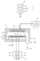
(Shortening of time required for temperature stabilization of the mounting table)
2 is a diagram for explaining a reduction in the time required for the temperature of the mounting table to become stable by the recipe updating method according to the embodiment, and shows an experimental result when a first recipe is updated to a second recipe.
図2の「第1レシピ」は、第1レシピを用いて載置台に載置された基板に対してプラズマ処理を施した結果を示す。第1レシピを用いる場合、プラズマを生成するステップS1、S2の間の中断期間において載置台の温度が設定温度(一例として、50℃)から降下し、印加タイミングの後に載置台の温度が第1レシピに対応する第1最大値である約52℃まで上昇している。載置台の温度が再び設定温度の50℃に安定するまでの時間は27secである。 "First recipe" in Figure 2 shows the results of performing plasma processing on a substrate placed on a mounting table using the first recipe. When the first recipe is used, the temperature of the mounting table drops from the set temperature (50°C, for example) during the interruption between steps S1 and S2 in which plasma is generated, and after the application timing, the temperature of the mounting table rises to about 52°C, which is the first maximum value corresponding to the first recipe. It takes 27 seconds for the temperature of the mounting table to stabilize again at the set temperature of 50°C.
図2の「第2レシピ」は、第2レシピを用いて載置台に載置された基板に対してプラズマ処理を施した結果を示す。第2レシピの印加タイミングは、載置台の温度が最小値まで降下する基準タイミングに変更されている。第2レシピを用いる場合、印加タイミングの後に載置台の温度が第2レシピに対応する第2最大値である約51.4℃まで上昇している。載置台の温度が再び設定温度の50℃に安定するまでの時間は約16secまで短縮されている。 "Second recipe" in Figure 2 shows the results of performing plasma processing on a substrate placed on a mounting table using the second recipe. The application timing of the second recipe has been changed to the reference timing at which the temperature of the mounting table drops to its minimum value. When the second recipe is used, the temperature of the mounting table rises to approximately 51.4°C, which is the second maximum value corresponding to the second recipe, after the application timing. The time until the temperature of the mounting table stabilizes again at the set temperature of 50°C has been reduced to approximately 16 seconds.
第1レシピによりプラズマ処理を施す場合、設定温度に調整された載置台が印加タイミングにおいて生成されるプラズマにより加熱される。このため、載置台の温度が設定温度から大幅に上昇し、第1レシピに対応する第1最大値が増大する。これに対して、第2レシピによりプラズマ処理を施す場合、載置台の温度が最小値まで降下する基準タイミングと印加タイミングとが一致するため、印加タイミングにおいて生成されるプラズマから載置台への入熱の影響が抑制される。このため、載置台の温度が設定温度に対してそれほど上昇せず、第2レシピに対応する第2最大値の増大が抑制される。結果として、載置台への高周波電力の印加後に発生するオーバーシュートが抑制され、載置台の温度の安定時間を短縮できる。 When plasma processing is performed according to the first recipe, the mounting table, adjusted to the set temperature, is heated by the plasma generated at the application timing. This causes the temperature of the mounting table to rise significantly from the set temperature, and the first maximum value corresponding to the first recipe increases. In contrast, when plasma processing is performed according to the second recipe, the reference timing at which the temperature of the mounting table drops to the minimum value coincides with the application timing, so the effect of heat input from the plasma generated at the application timing to the mounting table is suppressed. This causes the temperature of the mounting table to not rise as much above the set temperature, and the increase in the second maximum value corresponding to the second recipe is suppressed. As a result, the overshoot that occurs after the application of high-frequency power to the mounting table is suppressed, and the time it takes for the temperature of the mounting table to stabilize can be shortened.
(プラズマ処理装置の一例)
図3は、実施形態に係るレシピ更新方法の実行に用いられるプラズマ処理装置の一例を示す図である。図3に示すプラズマ処理装置1は、チャンバ10、ガス供給部20、高周波(RF:Radio Frequency)電力供給部30、排気システム40、及び制御部50を含む。
(An example of a plasma processing apparatus)
3 is a diagram showing an example of a plasma processing apparatus used in executing the recipe updating method according to the embodiment. The
本実施形態において、チャンバ10は、支持部11(載置台とも呼ぶ)及び上部電極シャワーヘッドアセンブリ12を含む。支持部11は、チャンバ10内の処理空間10sの下部領域に配置される。上部電極シャワーヘッドアセンブリ12は、支持部11の上方に配置され、チャンバ10の天板の一部として機能し得る。
In this embodiment, the
支持部11は、処理空間10sにおいて基板Wを支持するように構成される。本実施形態において、支持部11は、下部電極111、静電チャック112、及びエッジリング113を含む。静電チャック112は、下部電極111上に配置され、静電チャック112の上面で基板Wを支持するように構成される。エッジリング113は、下部電極111の周縁部上面において基板Wを囲むように配置される。支持部11の内部にはヒータ111aが設けられる。ヒータ111aは、ヒータ電源111bに接続される。ヒータ電源111bは、制御部50からの制御の下で、ヒータ111aに調整された電力を供給する。これにより、ヒータ111aが発する熱が制御され、支持部11の温度が調整される。
The support 11 is configured to support the substrate W in the
上部電極シャワーヘッドアセンブリ12は、ガス供給部20からの1又はそれ以上の処理ガスを処理空間10sに供給するように構成される。本実施形態において、上部電極シャワーヘッドアセンブリ12は、ガス入口12a、ガス拡散室12b、及び複数のガス出口12cを含む。ガス入口12aは、ガス供給部20及びガス拡散室12bと流体連通される。複数のガス出口12cは、ガス拡散室12b及び処理空間10sと流体連通される。本実施形態において、上部電極シャワーヘッドアセンブリ12は、1又はそれ以上の処理ガスをガス入口12aからガス拡散室12b及び複数のガス出口12cを介して処理空間10sに供給するように構成される。
The upper
ガス供給部20は、1又はそれ以上のガスソース21及び1又はそれ以上の流量制御器22を含んでもよい。本実施形態において、ガス供給部20は、1又はそれ以上の処理ガスを、各々のガスソース21から各々の流量制御器22を介してガス入口12aに供給するように構成される。流量制御器22は、例えばマスフローコントローラ又は圧力制御式の流量制御器を含んでもよい。更に、ガス供給部20は、1又はそれ以上の処理ガスの流量を変調又はパルス化する1又はそれ以上の流量変調デバイスを含んでもよい。
The
RF電力供給部30は、RF電力、例えば1又はそれ以上のRF信号を、下部電極111、上部電極シャワーヘッドアセンブリ12、又は、下部電極111及び上部電極シャワーヘッドアセンブリ12の双方のような1又はそれ以上の電極に供給するように構成される。本実施形態において、RF電力供給部30は、2つのRF生成部31a,31b及び2つの整合回路32a,32bを含む。本実施形態において示されたRF電力供給部30は、第1のRF信号を第1のRF生成部31aから第1の整合回路32aを介して下部電極111に供給するように構成される。RFスペクトルは、3Hz~3000GHzの範囲の電磁スペクトルの一部を包含する。半導体プロセスのような電子材料プロセスに関して、プラズマ生成のために用いられるRFスペクトルは、好ましくは100kHz~3GHz、より好ましくは200kHz~150MHzの範囲内である。例えば、第1のRF信号は、27MHz~100MHzの範囲内の周波数を有してもよい。また、本実施形態において示されたRF電力供給部30は、第2のRF信号を第2のRF生成部31bから第2の整合回路32bを介して下部電極111に供給するように構成される。例えば、第2のRF信号は、400kHz~13.56MHzの範囲内の周波数を有してもよい。代わりに、第2のRF生成部31bに代えて、DC(Direct Current)パルス生成部を用いてもよい。更に、図示は省略するが、ここでは他の実施形態が考慮される。例えば、代替実施形態において、RF電力供給部30は、第1のRF信号をRF生成部から下部電極111に供給し、第2のRF信号を他のRF生成部から下部電極111に供給し、第3のRF信号を更に他のRF生成部から下部電極111に供給するように構成されてもよい。加えて、他の代替実施形態において、DC電圧が上部電極シャワーヘッドアセンブリ12に印加されてもよい。また更に、種々の実施形態において、1又はそれ以上のRF信号(即ち、第1のRF信号、第2のRF信号等)の振幅がパルス化又は変調されてもよい。振幅変調は、オン状態とオフ状態との間、あるいは、2又はそれ以上の異なるオン状態の間でRF信号振幅をパルス化することを含んでもよい。RF信号の位相整合が制御されてもよく、2又はそれ以上のRF信号の振幅変調の位相整合は、同期化されてもよく、非同期であってもよい。
The
排気システム40は、例えばチャンバ10の底部に設けられた排気口10eに接続され得る。排気システム40は、圧力弁や、ターボ分子ポンプ、粗引きポンプ又はこれらの組み合わせのような真空ポンプを含んでもよい。
The
本実施形態において、制御部50は、ここで述べられる種々の工程をプラズマ処理装置1に実行させるコンピュータ実行可能な指示を処理する。制御部50は、ここで述べられる種々の工程を実行するようにプラズマ処理装置1の各要素を制御するように構成され得る。制御部50は、例えばコンピュータ51を含んでもよい。コンピュータ51は、例えば、処理部(CPU; Central Processing Unit)511、記憶部512、及び通信インターフェース513を含む。処理部511は、記憶部512に格納されたプログラムに基づいて種々の制御動作を行うように構成され得る。記憶部512は、RAM(Random Access Memory)、ROM(Read Only Memory)、及び、HDD(Hard Disk Drive)、SSD(Solid State Drive)等のような補助記憶装置からなるグループから選択される少なくとも1つのメモリタイプを含んでもよい。通信インターフェース513は、LAN(Local Area Network)等の通信回線を介してプラズマ処理装置1との間で通信してもよい。
In this embodiment, the
(実施形態の効果)
上記実施形態に係るレシピ更新方法は、プラズマ処理装置のレシピ更新方法である。実施形態に係るレシピ更新方法は、第1レシピを用いてプラズマ処理を施す工程と、基準タイミングと第1最大値とを計測する工程と、第2レシピを用いてプラズマ処理を施す工程と、第2最大値を計測する工程と、第1レシピを更新する工程とを含む。第1レシピを用いてプラズマ処理を施す工程は、プラズマ生成用の高周波電力の印加タイミングを含む第1レシピを用いて、載置台に載置された基板に対してプラズマ処理を施す。基準タイミングと第1最大値とを計測する工程は、第1レシピに対応付けて、載置台の温度が最小値まで降下する基準タイミングと、載置台の温度の第1最大値とを計測する。第2レシピを用いてプラズマ処理を施す工程は、第1レシピの印加タイミングを基準タイミングに変更して得られる第2レシピを用いて、基板に対してプラズマ処理を施す。第2最大値を計測する工程は、第2レシピに対応付けて、載置台の温度の第2最大値を計測する。第1レシピを更新する工程は、第2最大値が前記第1最大値よりも小さい場合に、前記第1レシピを前記第2レシピに更新する。これにより、実施形態に係るレシピ更新方法によれば、載置台への高周波電力の印加後に発生するオーバーシュートを抑制することができるため、高周波電力の印加後に載置台の温度が安定するまでの時間を短縮することができる。
(Effects of the embodiment)
The recipe updating method according to the embodiment is a recipe updating method for a plasma processing apparatus. The recipe updating method according to the embodiment includes a step of performing plasma processing using a first recipe, a step of measuring a reference timing and a first maximum value, a step of performing plasma processing using a second recipe, a step of measuring a second maximum value, and a step of updating the first recipe. The step of performing plasma processing using the first recipe performs plasma processing on a substrate placed on a mounting table using a first recipe including an application timing of high frequency power for plasma generation. The step of measuring the reference timing and the first maximum value measures a reference timing at which the temperature of the mounting table drops to a minimum value and a first maximum value of the temperature of the mounting table in association with the first recipe. The step of performing plasma processing using the second recipe performs plasma processing on a substrate using a second recipe obtained by changing the application timing of the first recipe to the reference timing. The step of measuring the second maximum value measures a second maximum value of the temperature of the mounting table in association with the second recipe. The step of updating the first recipe updates the first recipe to the second recipe when the second maximum value is smaller than the first maximum value. As a result, according to the recipe updating method of the embodiment, it is possible to suppress overshoot that occurs after application of high frequency power to the mounting table, and therefore it is possible to shorten the time until the temperature of the mounting table stabilizes after application of high frequency power.
また、実施形態に係るレシピ更新方法は、第nレシピ(nは3以上の自然数)を用いてプラズマ処理を施す工程と、第n最大値を計測する工程と、第(n-1)レシピを更新する工程とをさらに含む。第nレシピを用いてプラズマ処理を施す工程は、第1レシピを更新する工程の後、第(n-1)レシピの印加タイミングを早めて得られる第nレシピを用いて基板に対してプラズマ処理を施す。第n最大値を計測する工程は、第nレシピに対応付けて、載置台の温度の第n最大値を計測する。第(n-1)レシピを更新する工程は、第n最大値が第(n-1)レシピに対応付けて計測された第(n-1)最大値よりも小さい場合に、第(n-1)レシピを第nレシピに更新する。これにより、実施形態に係るレシピ更新方法によれば、第2レシピの印加タイミングをさらに早めて載置台の温度の最大値を小さくすることができ、載置台の温度が安定するまでの時間をより短縮することができる。 The recipe updating method according to the embodiment further includes a step of performing plasma processing using the nth recipe (n is a natural number of 3 or more), a step of measuring the nth maximum value, and a step of updating the (n-1)th recipe. In the step of performing plasma processing using the nth recipe, after the step of updating the first recipe, plasma processing is performed on the substrate using the nth recipe obtained by advancing the application timing of the (n-1)th recipe. In the step of measuring the nth maximum value, the nth maximum value of the temperature of the mounting table is measured in association with the nth recipe. In the step of updating the (n-1)th recipe, if the nth maximum value is smaller than the (n-1) maximum value measured in association with the (n-1)th recipe, the (n-1)th recipe is updated to the nth recipe. As a result, according to the recipe updating method according to the embodiment, the application timing of the second recipe can be further advanced to reduce the maximum value of the temperature of the mounting table, and the time until the temperature of the mounting table stabilizes can be further shortened.
また、実施形態において、第nレシピを用いてプラズマ処理を施す工程と、第n最大値を計測する工程と、第(n-1)レシピを更新する工程とは、第n最大値が第(n-1)最大値以上となるまで、繰り返される。そして、第(n-1)レシピを更新する工程は、第n最大値が第(n-1)最大値以上となる場合に、第(n-1)レシピの更新を中止する。これにより、実施形態に係るレシピ更新方法によれば、載置台の温度の最大値を最小化することができ、載置台の温度が安定するまでの時間をより短縮することができる。 In addition, in the embodiment, the process of performing plasma processing using the nth recipe, the process of measuring the nth maximum value, and the process of updating the (n-1)th recipe are repeated until the nth maximum value becomes equal to or greater than the (n-1)th maximum value. Then, in the process of updating the (n-1)th recipe, when the nth maximum value becomes equal to or greater than the (n-1)th maximum value, the updating of the (n-1)th recipe is stopped. As a result, according to the recipe updating method of the embodiment, the maximum value of the temperature of the mounting table can be minimized, and the time until the temperature of the mounting table stabilizes can be further shortened.
以上、実施形態について説明してきたが、今回開示された実施形態は、全ての点で例示であって制限的なものではないと考えられるべきである。実に、上記した実施形態は、多様な形態で具現され得る。また、上記の実施形態は、請求の範囲およびその趣旨を逸脱することなく、様々な形態で省略、置換、変更されてもよい。 Although the embodiments have been described above, the embodiments disclosed herein should be considered to be illustrative in all respects and not restrictive. Indeed, the above-described embodiments may be embodied in a variety of forms. Furthermore, the above-described embodiments may be omitted, substituted, or modified in various forms without departing from the scope and spirit of the claims.
例えば、上記の実施形態では、第1レシピの印加タイミングを基準タイミングに変更して得られる第2レシピを用いて載置台上の基板に対してプラズマ処理を施す場合を例に説明したが、開示の技術はこれに限定されない。例えば、第2レシピを用いてプラズマ処理を施す工程において、変更後の印加タイミングが到来した場合に、載置台に設けられたヒータへの供給電力を設定された設定電力から一時的に下げてもよい。これにより、載置台への高周波電力の印加時にヒータの加熱による温度上昇を抑制することができ、載置台の温度が安定するまでの時間をより短縮することができる。また、印加タイミングの後、載置台の温度が設定された設定温度に到達する時点で、ヒータへの供給電力を設定電力に戻してもよい。これにより、載置台への高周波電力の印加後に載置台の温度を設定温度に維持することができる。 For example, in the above embodiment, a case where plasma processing is performed on a substrate on a mounting table using a second recipe obtained by changing the application timing of the first recipe to a reference timing has been described as an example, but the disclosed technology is not limited to this. For example, in a process of performing plasma processing using the second recipe, when the changed application timing arrives, the power supplied to the heater provided on the mounting table may be temporarily reduced from the set power. This makes it possible to suppress the temperature rise caused by heating of the heater when high frequency power is applied to the mounting table, and further shortens the time until the temperature of the mounting table stabilizes. In addition, after the application timing, when the temperature of the mounting table reaches the set temperature, the power supplied to the heater may be returned to the set power. This makes it possible to maintain the temperature of the mounting table at the set temperature after the application of high frequency power to the mounting table.
1 プラズマ処理装置
11 支持部(載置台)
30 RF電力供給部
111a ヒータ
111b ヒータ電源
50 制御部
51 コンピュータ
511 処理部
512 記憶部
513 通信インターフェース
W 基板
1 Plasma processing apparatus 11 Support portion (mounting table)
30 RF
Claims (5)
プラズマ生成用の高周波電力の印加タイミングを含む第1レシピを用いて、載置台に載置された基板に対してプラズマ処理を施す工程と、
前記第1レシピに対応付けて、前記載置台の温度が最小値まで降下する基準タイミングと、前記載置台の温度の第1最大値とを計測する工程と、
前記第1レシピの前記印加タイミングを前記基準タイミングに変更して得られる第2レシピを用いて、前記基板に対してプラズマ処理を施す工程と、
前記第2レシピに対応付けて、前記載置台の温度の第2最大値を計測する工程と、
前記第2最大値が前記第1最大値よりも小さい場合に、前記第1レシピを前記第2レシピに更新する工程と
を含む、レシピ更新方法。 A recipe updating method for a plasma processing apparatus, comprising:
performing a plasma process on a substrate placed on a placement table using a first recipe including a timing for applying high frequency power for generating plasma;
measuring a reference time when the temperature of the mounting table drops to a minimum value and a first maximum value of the temperature of the mounting table in association with the first recipe;
performing a plasma process on the substrate using a second recipe obtained by changing the application timing of the first recipe to the reference timing;
measuring a second maximum value of the temperature of the mounting table in association with the second recipe;
if the second maximum value is less than the first maximum value, updating the first recipe to the second recipe.
前記第nレシピに対応付けて、前記載置台の温度の第n最大値を計測する工程と、
前記第n最大値が前記第(n-1)レシピに対応付けて計測された第(n-1)最大値よりも小さい場合に、前記第(n-1)レシピを前記第nレシピに更新する工程と
をさらに含む、請求項1に記載のレシピ更新方法。 After updating the first recipe, performing a plasma process on the substrate using an n-th recipe obtained by advancing the application timing of the (n-1)-th recipe (n is a natural number of 3 or more);
measuring an n-th maximum value of the temperature of the mounting table in association with the n-th recipe;
and updating the (n-1) recipe to the n recipe when the nth maximum value is smaller than the (n-1)th maximum value measured in association with the (n-1) recipe.
前記第(n-1)レシピを更新する工程は、前記第n最大値が前記第(n-1)最大値以上となる場合に、前記第(n-1)レシピの更新を中止する、請求項2に記載のレシピ更新方法。 the steps of performing plasma processing using the nth recipe, measuring the nth maximum value, and updating the (n-1)th recipe are repeated until the nth maximum value becomes equal to or greater than the (n-1)th maximum value;
3. The recipe updating method according to claim 2, wherein the step of updating the (n-1) recipe includes canceling updating of the (n-1) recipe when the n maximum value becomes equal to or greater than the (n-1) maximum value.
Priority Applications (3)
| Application Number | Priority Date | Filing Date | Title |
|---|---|---|---|
| JP2020183470A JP7561575B2 (en) | 2020-11-02 | 2020-11-02 | How to update recipes |
| KR1020210147750A KR102888083B1 (en) | 2020-11-02 | 2021-11-01 | Recipe updating method |
| US17/517,253 US12211678B2 (en) | 2020-11-02 | 2021-11-02 | Recipe updating method |
Applications Claiming Priority (1)
| Application Number | Priority Date | Filing Date | Title |
|---|---|---|---|
| JP2020183470A JP7561575B2 (en) | 2020-11-02 | 2020-11-02 | How to update recipes |
Publications (2)
| Publication Number | Publication Date |
|---|---|
| JP2022073471A JP2022073471A (en) | 2022-05-17 |
| JP7561575B2 true JP7561575B2 (en) | 2024-10-04 |
Family
ID=81379921
Family Applications (1)
| Application Number | Title | Priority Date | Filing Date |
|---|---|---|---|
| JP2020183470A Active JP7561575B2 (en) | 2020-11-02 | 2020-11-02 | How to update recipes |
Country Status (3)
| Country | Link |
|---|---|
| US (1) | US12211678B2 (en) |
| JP (1) | JP7561575B2 (en) |
| KR (1) | KR102888083B1 (en) |
Families Citing this family (2)
| Publication number | Priority date | Publication date | Assignee | Title |
|---|---|---|---|---|
| JP7561575B2 (en) * | 2020-11-02 | 2024-10-04 | 東京エレクトロン株式会社 | How to update recipes |
| JP7711027B2 (en) | 2022-04-27 | 2025-07-22 | シチズン時計株式会社 | Printer |
Citations (4)
| Publication number | Priority date | Publication date | Assignee | Title |
|---|---|---|---|---|
| JP2003017471A (en) | 2001-06-29 | 2003-01-17 | Hitachi Ltd | Plasma processing apparatus and processing method |
| JP2013102041A (en) | 2011-11-08 | 2013-05-23 | Tokyo Electron Ltd | Temperature control method, control apparatus, and plasma processing apparatus |
| JP2019091880A (en) | 2017-11-16 | 2019-06-13 | 東京エレクトロン株式会社 | Plasma processing apparatus, temperature control method and temperature control program |
| JP2020115498A (en) | 2019-01-17 | 2020-07-30 | 東京エレクトロン株式会社 | Etching method and etching equipment |
Family Cites Families (17)
| Publication number | Priority date | Publication date | Assignee | Title |
|---|---|---|---|---|
| US7459100B2 (en) * | 2004-12-22 | 2008-12-02 | Lam Research Corporation | Methods and apparatus for sequentially alternating among plasma processes in order to optimize a substrate |
| JP5165878B2 (en) * | 2006-10-20 | 2013-03-21 | 東京エレクトロン株式会社 | Substrate processing apparatus control device, control method, and storage medium storing control program |
| US9059101B2 (en) * | 2011-07-07 | 2015-06-16 | Lam Research Corporation | Radiofrequency adjustment for instability management in semiconductor processing |
| US9280151B2 (en) * | 2012-05-15 | 2016-03-08 | Wafertech, Llc | Recipe management system and method |
| US9263350B2 (en) * | 2014-06-03 | 2016-02-16 | Lam Research Corporation | Multi-station plasma reactor with RF balancing |
| JP6525751B2 (en) * | 2015-06-11 | 2019-06-05 | 東京エレクトロン株式会社 | Temperature control method and plasma processing apparatus |
| JP6570894B2 (en) * | 2015-06-24 | 2019-09-04 | 東京エレクトロン株式会社 | Temperature control method |
| JP7161896B2 (en) * | 2018-09-20 | 2022-10-27 | 株式会社Screenホールディングス | Substrate processing apparatus and substrate processing system |
| JP7280113B2 (en) * | 2018-10-05 | 2023-05-23 | 東京エレクトロン株式会社 | PLASMA PROCESSING APPARATUS, MONITORING METHOD AND MONITORING PROGRAM |
| CN114450779B (en) * | 2019-09-27 | 2025-02-25 | 松下知识产权经营株式会社 | Cutting system and cutting method |
| JP7561575B2 (en) * | 2020-11-02 | 2024-10-04 | 東京エレクトロン株式会社 | How to update recipes |
| US20220269177A1 (en) * | 2021-02-23 | 2022-08-25 | Tokyo Electron Limited | Sensor technology integration into coating track |
| JP2022185241A (en) * | 2021-06-02 | 2022-12-14 | 東京エレクトロン株式会社 | Plasma processing device and plasma processing method |
| JP7813563B2 (en) * | 2021-11-19 | 2026-02-13 | 東京エレクトロン株式会社 | Substrate processing apparatus and substrate processing method |
| CN117917188B (en) * | 2022-03-08 | 2025-03-21 | 东京毅力科创株式会社 | Methods for reducing leakage of heat transfer gas |
| JP2023169963A (en) * | 2022-05-18 | 2023-12-01 | 東京エレクトロン株式会社 | Recipe display method and substrate processing system |
| TW202507556A (en) * | 2023-02-01 | 2025-02-16 | 日商東京威力科創股份有限公司 | Computer program, information processing method and information processing device |
-
2020
- 2020-11-02 JP JP2020183470A patent/JP7561575B2/en active Active
-
2021
- 2021-11-01 KR KR1020210147750A patent/KR102888083B1/en active Active
- 2021-11-02 US US17/517,253 patent/US12211678B2/en active Active
Patent Citations (4)
| Publication number | Priority date | Publication date | Assignee | Title |
|---|---|---|---|---|
| JP2003017471A (en) | 2001-06-29 | 2003-01-17 | Hitachi Ltd | Plasma processing apparatus and processing method |
| JP2013102041A (en) | 2011-11-08 | 2013-05-23 | Tokyo Electron Ltd | Temperature control method, control apparatus, and plasma processing apparatus |
| JP2019091880A (en) | 2017-11-16 | 2019-06-13 | 東京エレクトロン株式会社 | Plasma processing apparatus, temperature control method and temperature control program |
| JP2020115498A (en) | 2019-01-17 | 2020-07-30 | 東京エレクトロン株式会社 | Etching method and etching equipment |
Also Published As
| Publication number | Publication date |
|---|---|
| US12211678B2 (en) | 2025-01-28 |
| US20220137603A1 (en) | 2022-05-05 |
| JP2022073471A (en) | 2022-05-17 |
| KR20220059422A (en) | 2022-05-10 |
| KR102888083B1 (en) | 2025-11-18 |
Similar Documents
| Publication | Publication Date | Title |
|---|---|---|
| JP7455174B2 (en) | RF generator and method | |
| JP2024097015A (en) | Plasma processing apparatus and power supply system | |
| JP7638168B2 (en) | Plasma processing apparatus and plasma processing method | |
| JP2020092036A (en) | Control method and plasma processing apparatus | |
| JP7766765B2 (en) | Plasma processing equipment | |
| TWI905447B (en) | Plasma processing apparatus and plasma processing method | |
| JP7561575B2 (en) | How to update recipes | |
| TW202418887A (en) | Plasma processing apparatus, plasma processing method, pressure valve control device, pressure valve control method, and pressure regulation system | |
| US12451336B2 (en) | Substrate processing apparatus and substrate processing method | |
| WO2023127655A1 (en) | Plasma treatment device, power supply system, control method, program, and storage medium | |
| JP7419611B1 (en) | Method for reducing the amount of heat transfer gas leakage | |
| CN110634758B (en) | Substrate processing apparatus, storage medium, and substrate processing method | |
| KR20250157479A (en) | Plasma processing apparatus and plasma processing method | |
| JP7671717B2 (en) | Plasma processing apparatus and plasma processing method | |
| JP7825531B2 (en) | Plasma processing apparatus and method for suppressing abnormal discharge | |
| JP7582749B2 (en) | Temperature control method and temperature control device | |
| JP7504004B2 (en) | SUBSTRATE PROCESSING APPARATUS AND SUBSTRATE PROCESSING METHOD | |
| JP2023178190A (en) | Plasma processing equipment, plasma processing method, pressure valve control device, pressure valve control method, and pressure adjustment system | |
| KR20230032975A (en) | Plasma processing apparatus and abnormal discharge control method | |
| WO2025182632A1 (en) | Plasma processing device | |
| WO2024204321A1 (en) | Etching device and etching method | |
| KR20210117165A (en) | Substrate processing method and substrate processing apparatus | |
| CN117174563A (en) | Plasma processing device and method, pressure valve control device and method, and pressure regulating system | |
| JP2022102855A (en) | Plasma processing device and plasma processing method |
Legal Events
| Date | Code | Title | Description |
|---|---|---|---|
| A621 | Written request for application examination |
Free format text: JAPANESE INTERMEDIATE CODE: A621 Effective date: 20230704 |
|
| A977 | Report on retrieval |
Free format text: JAPANESE INTERMEDIATE CODE: A971007 Effective date: 20240328 |
|
| A131 | Notification of reasons for refusal |
Free format text: JAPANESE INTERMEDIATE CODE: A131 Effective date: 20240423 |
|
| A521 | Request for written amendment filed |
Free format text: JAPANESE INTERMEDIATE CODE: A523 Effective date: 20240502 |
|
| TRDD | Decision of grant or rejection written | ||
| A01 | Written decision to grant a patent or to grant a registration (utility model) |
Free format text: JAPANESE INTERMEDIATE CODE: A01 Effective date: 20240827 |
|
| A61 | First payment of annual fees (during grant procedure) |
Free format text: JAPANESE INTERMEDIATE CODE: A61 Effective date: 20240924 |
|
| R150 | Certificate of patent or registration of utility model |
Ref document number: 7561575 Country of ref document: JP Free format text: JAPANESE INTERMEDIATE CODE: R150 |