EP4516641A1 - Seitenteilstruktur einer fahrzeugkarosserie - Google Patents
Seitenteilstruktur einer fahrzeugkarosserie Download PDFInfo
- Publication number
- EP4516641A1 EP4516641A1 EP23815690.5A EP23815690A EP4516641A1 EP 4516641 A1 EP4516641 A1 EP 4516641A1 EP 23815690 A EP23815690 A EP 23815690A EP 4516641 A1 EP4516641 A1 EP 4516641A1
- Authority
- EP
- European Patent Office
- Prior art keywords
- vehicle
- collision energy
- width direction
- battery pack
- collision
- Prior art date
- Legal status (The legal status is an assumption and is not a legal conclusion. Google has not performed a legal analysis and makes no representation as to the accuracy of the status listed.)
- Pending
Links
Images


Classifications
-
- B—PERFORMING OPERATIONS; TRANSPORTING
- B62—LAND VEHICLES FOR TRAVELLING OTHERWISE THAN ON RAILS
- B62D—MOTOR VEHICLES; TRAILERS
- B62D21/00—Understructures, i.e. chassis frame on which a vehicle body may be mounted
- B62D21/15—Understructures, i.e. chassis frame on which a vehicle body may be mounted having impact absorbing means, e.g. a frame designed to permanently or temporarily change shape or dimension upon impact with another body
- B62D21/157—Understructures, i.e. chassis frame on which a vehicle body may be mounted having impact absorbing means, e.g. a frame designed to permanently or temporarily change shape or dimension upon impact with another body for side impacts
-
- F—MECHANICAL ENGINEERING; LIGHTING; HEATING; WEAPONS; BLASTING
- F16—ENGINEERING ELEMENTS AND UNITS; GENERAL MEASURES FOR PRODUCING AND MAINTAINING EFFECTIVE FUNCTIONING OF MACHINES OR INSTALLATIONS; THERMAL INSULATION IN GENERAL
- F16F—SPRINGS; SHOCK-ABSORBERS; MEANS FOR DAMPING VIBRATION
- F16F7/00—Vibration-dampers; Shock-absorbers
- F16F7/12—Vibration-dampers; Shock-absorbers using plastic deformation of members
-
- B—PERFORMING OPERATIONS; TRANSPORTING
- B60—VEHICLES IN GENERAL
- B60K—ARRANGEMENT OR MOUNTING OF PROPULSION UNITS OR OF TRANSMISSIONS IN VEHICLES; ARRANGEMENT OR MOUNTING OF PLURAL DIVERSE PRIME-MOVERS IN VEHICLES; AUXILIARY DRIVES FOR VEHICLES; INSTRUMENTATION OR DASHBOARDS FOR VEHICLES; ARRANGEMENTS IN CONNECTION WITH COOLING, AIR INTAKE, GAS EXHAUST OR FUEL SUPPLY OF PROPULSION UNITS IN VEHICLES
- B60K1/00—Arrangement or mounting of electrical propulsion units
- B60K1/04—Arrangement or mounting of electrical propulsion units of the electric storage means for propulsion
-
- B—PERFORMING OPERATIONS; TRANSPORTING
- B62—LAND VEHICLES FOR TRAVELLING OTHERWISE THAN ON RAILS
- B62D—MOTOR VEHICLES; TRAILERS
- B62D21/00—Understructures, i.e. chassis frame on which a vehicle body may be mounted
- B62D21/15—Understructures, i.e. chassis frame on which a vehicle body may be mounted having impact absorbing means, e.g. a frame designed to permanently or temporarily change shape or dimension upon impact with another body
-
- B—PERFORMING OPERATIONS; TRANSPORTING
- B62—LAND VEHICLES FOR TRAVELLING OTHERWISE THAN ON RAILS
- B62D—MOTOR VEHICLES; TRAILERS
- B62D25/00—Superstructure or monocoque structure sub-units; Parts or details thereof not otherwise provided for
- B62D25/02—Side panels
- B62D25/025—Side sills thereof
-
- B—PERFORMING OPERATIONS; TRANSPORTING
- B62—LAND VEHICLES FOR TRAVELLING OTHERWISE THAN ON RAILS
- B62D—MOTOR VEHICLES; TRAILERS
- B62D25/00—Superstructure or monocoque structure sub-units; Parts or details thereof not otherwise provided for
- B62D25/20—Floors or bottom sub-units
-
- B—PERFORMING OPERATIONS; TRANSPORTING
- B62—LAND VEHICLES FOR TRAVELLING OTHERWISE THAN ON RAILS
- B62D—MOTOR VEHICLES; TRAILERS
- B62D25/00—Superstructure or monocoque structure sub-units; Parts or details thereof not otherwise provided for
- B62D25/20—Floors or bottom sub-units
- B62D25/2009—Floors or bottom sub-units in connection with other superstructure subunits
- B62D25/2036—Floors or bottom sub-units in connection with other superstructure subunits the subunits being side panels, sills or pillars
-
- H—ELECTRICITY
- H01—ELECTRIC ELEMENTS
- H01M—PROCESSES OR MEANS, e.g. BATTERIES, FOR THE DIRECT CONVERSION OF CHEMICAL ENERGY INTO ELECTRICAL ENERGY
- H01M50/00—Constructional details or processes of manufacture of the non-active parts of electrochemical cells other than fuel cells, e.g. hybrid cells
- H01M50/20—Mountings; Secondary casings or frames; Racks, modules or packs; Suspension devices; Shock absorbers; Transport or carrying devices; Holders
- H01M50/233—Mountings; Secondary casings or frames; Racks, modules or packs; Suspension devices; Shock absorbers; Transport or carrying devices; Holders characterised by physical properties of casings or racks, e.g. dimensions
- H01M50/242—Mountings; Secondary casings or frames; Racks, modules or packs; Suspension devices; Shock absorbers; Transport or carrying devices; Holders characterised by physical properties of casings or racks, e.g. dimensions adapted for protecting batteries against vibrations, collision impact or swelling
-
- H—ELECTRICITY
- H01—ELECTRIC ELEMENTS
- H01M—PROCESSES OR MEANS, e.g. BATTERIES, FOR THE DIRECT CONVERSION OF CHEMICAL ENERGY INTO ELECTRICAL ENERGY
- H01M50/00—Constructional details or processes of manufacture of the non-active parts of electrochemical cells other than fuel cells, e.g. hybrid cells
- H01M50/20—Mountings; Secondary casings or frames; Racks, modules or packs; Suspension devices; Shock absorbers; Transport or carrying devices; Holders
- H01M50/249—Mountings; Secondary casings or frames; Racks, modules or packs; Suspension devices; Shock absorbers; Transport or carrying devices; Holders specially adapted for aircraft or vehicles, e.g. cars or trains
-
- B—PERFORMING OPERATIONS; TRANSPORTING
- B60—VEHICLES IN GENERAL
- B60K—ARRANGEMENT OR MOUNTING OF PROPULSION UNITS OR OF TRANSMISSIONS IN VEHICLES; ARRANGEMENT OR MOUNTING OF PLURAL DIVERSE PRIME-MOVERS IN VEHICLES; AUXILIARY DRIVES FOR VEHICLES; INSTRUMENTATION OR DASHBOARDS FOR VEHICLES; ARRANGEMENTS IN CONNECTION WITH COOLING, AIR INTAKE, GAS EXHAUST OR FUEL SUPPLY OF PROPULSION UNITS IN VEHICLES
- B60K1/00—Arrangement or mounting of electrical propulsion units
- B60K1/04—Arrangement or mounting of electrical propulsion units of the electric storage means for propulsion
- B60K2001/0405—Arrangement or mounting of electrical propulsion units of the electric storage means for propulsion characterised by their position
- B60K2001/0438—Arrangement under the floor
-
- B—PERFORMING OPERATIONS; TRANSPORTING
- B60—VEHICLES IN GENERAL
- B60L—PROPULSION OF ELECTRICALLY-PROPELLED VEHICLES; SUPPLYING ELECTRIC POWER FOR AUXILIARY EQUIPMENT OF ELECTRICALLY-PROPELLED VEHICLES; ELECTRODYNAMIC BRAKE SYSTEMS FOR VEHICLES IN GENERAL; MAGNETIC SUSPENSION OR LEVITATION FOR VEHICLES; MONITORING OPERATING VARIABLES OF ELECTRICALLY-PROPELLED VEHICLES; ELECTRIC SAFETY DEVICES FOR ELECTRICALLY-PROPELLED VEHICLES
- B60L50/00—Electric propulsion with power supplied within the vehicle
- B60L50/50—Electric propulsion with power supplied within the vehicle using propulsion power supplied by batteries or fuel cells
- B60L50/60—Electric propulsion with power supplied within the vehicle using propulsion power supplied by batteries or fuel cells using power supplied by batteries
- B60L50/64—Constructional details of batteries specially adapted for electric vehicles
-
- B—PERFORMING OPERATIONS; TRANSPORTING
- B60—VEHICLES IN GENERAL
- B60L—PROPULSION OF ELECTRICALLY-PROPELLED VEHICLES; SUPPLYING ELECTRIC POWER FOR AUXILIARY EQUIPMENT OF ELECTRICALLY-PROPELLED VEHICLES; ELECTRODYNAMIC BRAKE SYSTEMS FOR VEHICLES IN GENERAL; MAGNETIC SUSPENSION OR LEVITATION FOR VEHICLES; MONITORING OPERATING VARIABLES OF ELECTRICALLY-PROPELLED VEHICLES; ELECTRIC SAFETY DEVICES FOR ELECTRICALLY-PROPELLED VEHICLES
- B60L50/00—Electric propulsion with power supplied within the vehicle
- B60L50/50—Electric propulsion with power supplied within the vehicle using propulsion power supplied by batteries or fuel cells
- B60L50/60—Electric propulsion with power supplied within the vehicle using propulsion power supplied by batteries or fuel cells using power supplied by batteries
- B60L50/66—Arrangements of batteries
-
- B—PERFORMING OPERATIONS; TRANSPORTING
- B60—VEHICLES IN GENERAL
- B60Y—INDEXING SCHEME RELATING TO ASPECTS CROSS-CUTTING VEHICLE TECHNOLOGY
- B60Y2200/00—Type of vehicle
- B60Y2200/90—Vehicles comprising electric prime movers
- B60Y2200/91—Electric vehicles
-
- B—PERFORMING OPERATIONS; TRANSPORTING
- B60—VEHICLES IN GENERAL
- B60Y—INDEXING SCHEME RELATING TO ASPECTS CROSS-CUTTING VEHICLE TECHNOLOGY
- B60Y2306/00—Other features of vehicle sub-units
- B60Y2306/01—Reducing damages in case of crash, e.g. by improving battery protection
-
- H—ELECTRICITY
- H01—ELECTRIC ELEMENTS
- H01M—PROCESSES OR MEANS, e.g. BATTERIES, FOR THE DIRECT CONVERSION OF CHEMICAL ENERGY INTO ELECTRICAL ENERGY
- H01M2220/00—Batteries for particular applications
- H01M2220/20—Batteries in motive systems, e.g. vehicle, ship, plane
Definitions
- the present invention relates to an automotive body side structure such as a battery powered vehicle (battery electric vehicle) in which a battery pack is disposed vehicle inside in the vehicle width direction relative to a side sill.
- a battery powered vehicle battery electric vehicle
- a battery pack is disposed vehicle inside in the vehicle width direction relative to a side sill.
- a battery pack accommodating a large battery is disposed on a floor portion of a lower part of a vehicle body.
- a lithium (Li) based material is often used for the battery, when the battery pack is damaged at the time of a collision and liquid leakage from the battery occurs, there is a possibility of fire, and thus a structure for protecting the battery pack is required.
- Side sills are provided on both outer sides in the vehicle width direction to protect the battery pack, and the battery pack is disposed between the side sills.
- the present invention has been made to solve the above problems, and an object of the present invention is to provide an automotive body side structure capable of efficiently and reliably absorbing collision energy and protecting a battery pack at a time of a side collision of a vehicle body including a side sill and the battery pack disposed vehicle inside in the vehicle width direction relative to the side sill.
- An automotive body side structure includes: a side sill extending in a vehicle length direction; and a battery pack disposed vehicle inside in a vehicle width direction relative to the side sill, wherein the automotive body side structure includes a collision energy absorptive part having a substantially U-shaped cross section, the substantially U-shaped cross section including: a bottom portion substantially parallel to a vehicle height direction; and a pair of side wall portions continuous from an upper end and a lower end of the bottom portion, the collision energy absorptive part is provided in a protruding shape toward vehicle outside in the vehicle width direction while securing a space with the side sill on an outer peripheral side in the vehicle width direction of the battery pack, and the collision energy absorptive part is made of a steel sheet having a tensile strength of 270 MPa-class or more and 340 MPa-class or less and a plate thickness of 1.0 mm or more and 1.4 mm or less, and at a time of a side collision in which a collision load is
- the collision energy absorptive part may have an aspect ratio of a width in the vehicle width direction with respect to a height in the vehicle height direction in a range of 0.4 or more and 2.5 or less.
- the collision energy absorptive part may be inclined in a direction in which the pair of side wall portions approach each other toward vehicle outside in the vehicle width direction.
- the collision energy absorptive part may include one of the side wall portions parallel to a horizontal line in the vehicle width direction and another one of the side wall portions inclined in a direction approaching the one of the side wall portions toward vehicle outside in the vehicle width direction.
- the present invention it is possible to make it difficult to transfer the collision load input to the vehicle to the battery pack at a time of a side collision of the vehicle in which the battery pack is disposed vehicle inside in the vehicle width direction relative to the side sill.
- deformation of the battery pack can be suppressed at the time of a side collision, the battery pack of a battery powered vehicle or the like can be protected, and a safe vehicle can be made.
- an automotive body side structure 1 includes a side sill 3 extending in the vehicle length direction, a battery pack 5 disposed vehicle inside in the vehicle width direction relative to the side sill 3, a floor cross member 7, and a ground side cross member 9.
- the automotive body side structure 1 according to the embodiment of the present invention includes a collision energy absorptive part 11 on the outer peripheral side in the vehicle width direction of the battery pack 5.
- an automotive body side structure 1 according to the present embodiment will be described with reference to FIG. 1 .
- elements having the same functional configuration are denoted by the same reference numerals, and redundant description will be omitted.
- the side sill 3 includes a side sill inner 3a having a groove shape that opens toward vehicle outside in the vehicle width direction, and a side sill outer 3b having a groove shape that opens toward vehicle inside in the vehicle width direction.
- the side sill inner 3a and the side sill outer 3b face each other on the opening side, and a vehicle body upper side end portion and a vehicle body lower side end portion are joined to form a closed cross section structure.
- the groove shape of the side sill inner 3a has a hat-shaped cross section by a bottom portion 3a1 substantially parallel to the vehicle height direction and a pair of side wall portions 3a2 and 3a3 continuous from the upper end and the lower end of the bottom portion 3a1.
- the battery pack 5 has a battery cell (not illustrated) mounted therein, and includes a battery pack upper 5a and a battery pack lower 5b.
- the battery pack 5 is supported by a battery frame assembly 13 disposed on the outer peripheral side in the vehicle width direction.
- the battery frame assembly 13 includes a plurality of steel sheet parts.
- the floor cross member 7 is disposed above the battery pack 5 in the vehicle, and a vehicle outer side end portion 7a in the vehicle width direction is connected to the upper part of the side sill inner 3a.
- the collision energy absorptive part 11 is made of a steel sheet having a tensile strength of 270 MPa-class or more and 340 MPa-class or less and a plate thickness of 1.0 mm or more and 1.4 mm or less.
- the collision energy absorptive part 11 is joined to the outer peripheral face of the battery frame assembly 13 along the battery frame assembly 13 over an entire length of or a partial length of the vehicle length direction.
- the range of the tensile strength and the plate thickness of the steel sheet used for the collision energy absorptive part 11 will be described in Examples described later.
- the collision energy absorptive part 11 is deformed to absorb the collision energy to reduce a load transferred to the battery pack 5.
- An impact absorption part (corresponding to the collision energy absorptive part of the present application) in the technique disclosed in Patent Literature 1 absorbs collision energy while deforming the impact absorption part itself at the time of a side collision of a vehicle.
- a collision load is transferred to the battery pack disposed vehicle inside in the vehicle width direction during deformation of the impact absorption part, and the battery pack may be damaged.
- the automotive body side structure 1 has a cross-sectional structure that easily deforms the collision energy absorptive part 11, and is made of a thin steel sheet having a low tensile strength of 270 MPa-class or more and 340 MPa-class or less and a plate thickness of 1.0 mm or more and 1.4 mm or less.
- the collision energy absorptive part 11 is deformed to absorb the collision energy.
- the collision energy absorptive part 11 is set so that the aspect ratio (W/H) of the width W in the vehicle width direction with respect to the height H in the vehicle height direction is within the range of 0.4 or more and 2.5 or less.
- the collision energy absorptive part 11 can be provided between the side sill 3 and the battery pack 5, and the collision energy can be sufficiently absorbed by the collision energy absorptive part 11 at the time of the side collision.
- the pair of side wall portions 11b and 11c are horizontal in the vehicle width direction.
- a substantially U-shaped cross section 23d having a bottom portion 23a substantially parallel to the vehicle height direction and a pair of side wall portions 23b and 23c continuous from upper and lower ends of the bottom portion 23a is provided, and the pair of side wall portions 23b and 23c is inclined in a direction approaching each other toward vehicle outside in the vehicle width direction.
- the inclination angles of the side wall portions 23b and 23c are preferably 20° or less with respect to the horizontal line in the vehicle width direction.
- the inclination angle of the side wall portion is an acute angle with respect to the horizontal line (hereinafter, the same shall apply).
- a substantially U-shaped cross section 27d having a bottom portion 27a substantially parallel to the vehicle height direction and a pair of side wall portions 27b and 27c continuous from upper and lower ends of the bottom portion 27a is provided, the side wall portion 27b is parallel to the horizontal line in the vehicle width direction, and the side wall portion 27c is inclined in a direction approaching the side wall portion 27b toward vehicle outside in the vehicle width direction.
- the inclined side wall portion 27c preferably has an inclination angle of 20° or less with respect to the horizontal line in the vehicle width direction.
- the collision energy absorptive part has an inclined side wall portion, and thus, the collision energy absorptive part has an inclined side wall portion in which the cross section expands as the deformation progresses, so that the collision energy absorptive part can be easily collapsed at the initial stage of contact, and can be greatly deformed at the later stage of contact. Therefore, it is possible to further reduce the load transferred to the battery pack at the time of a side collision.
- the reason why the inclination angle of the inclined side wall portions 23b and 23c or the inclination angle of the inclined side wall portion 27c has an upper limit of 20° is that when the inclination angle is larger than 20°, the side wall portions are less likely to be crushed or are buckled during plastic deformation so that the side wall portions are not completely crushed. On the other hand, when the inclination angle of the inclined side wall portions 23b and 23c or the inclined side wall portion 27c is 20° or less, the side wall portions 23b and 23c or the side wall portion 27b can be easily crushed, which is preferable in terms of absorbing collision energy.
- the automotive body side structure 1 includes the battery frame assembly 13, and the collision energy absorptive part 11 is provided on the outer peripheral face of the battery frame assembly 13 in the vehicle width direction.
- the automotive body side structure according to the present invention may not include the battery frame assembly.
- the collision energy absorptive part may be provided on the outer peripheral face of the battery pack in the vehicle width direction.
- the floor cross member 7 is disposed above the battery pack 5, and the ground side cross member 9 is disposed below the battery pack 5.
- the floor cross member 7 may be disposed. Even in this case, after the side sill is deformed and comes into contact with the collision energy absorptive part, the collision energy absorptive part is deformed and absorbs the collision energy, so that the load transferred to the battery pack can be reduced and the deformation of the battery pack can be suppressed.
- the collision energy absorptive part 11 is provided on the battery pack 5 while securing a predetermined space with the side sill 3.
- the width W of the collision energy absorptive part 11 is preferably set such that the bottom portion 11a of the collision energy absorptive part 11 is located vehicle inside in the vehicle width direction relative to the innermost position in the side sill 3 inside the vehicle (the position in the vehicle width direction of the bottom portion 3a1 of the side sill inner 3a).
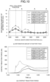
- the vehicle 101 was accelerated to 29 km/h in the vehicle width direction, and collided with the pole 103 which is a rigid body with respect to the side face of the vehicle 101.
- the side sill 3 (see FIG. 1 ) is locally deformed and advances inside the vehicle. Therefore, in the present example, the deformation amount of the battery pack 5 in the side collision process and the load input to the battery pack 5 were evaluated.
- the side wall portions 11b and 11c of the collision energy absorptive part 11 are both horizontal in the vehicle width direction, and the width W is 50 mm and the height H is 35 mm.
- the width W of the collision energy absorptive part 11 is set to be smaller than that in Invention Example 1 to be 40 mm.
Landscapes
- Engineering & Computer Science (AREA)
- Chemical & Material Sciences (AREA)
- Mechanical Engineering (AREA)
- Combustion & Propulsion (AREA)
- Transportation (AREA)
- General Engineering & Computer Science (AREA)
- Electrochemistry (AREA)
- General Chemical & Material Sciences (AREA)
- Chemical Kinetics & Catalysis (AREA)
- Aviation & Aerospace Engineering (AREA)
- Body Structure For Vehicles (AREA)
- Arrangement Or Mounting Of Propulsion Units For Vehicles (AREA)
- Vibration Dampers (AREA)
Applications Claiming Priority (2)
| Application Number | Priority Date | Filing Date | Title |
|---|---|---|---|
| JP2022090636A JP7394174B1 (ja) | 2022-06-03 | 2022-06-03 | 車体側部構造 |
| PCT/JP2023/017303 WO2023233929A1 (ja) | 2022-06-03 | 2023-05-08 | 車体側部構造 |
Publications (2)
| Publication Number | Publication Date |
|---|---|
| EP4516641A1 true EP4516641A1 (de) | 2025-03-05 |
| EP4516641A4 EP4516641A4 (de) | 2025-08-27 |
Family
ID=89023252
Family Applications (1)
| Application Number | Title | Priority Date | Filing Date |
|---|---|---|---|
| EP23815690.5A Pending EP4516641A4 (de) | 2022-06-03 | 2023-05-08 | Seitenteilstruktur einer fahrzeugkarosserie |
Country Status (7)
| Country | Link |
|---|---|
| US (1) | US20250313269A1 (de) |
| EP (1) | EP4516641A4 (de) |
| JP (1) | JP7394174B1 (de) |
| KR (1) | KR20250006247A (de) |
| CN (1) | CN119301033A (de) |
| MX (1) | MX2024014954A (de) |
| WO (1) | WO2023233929A1 (de) |
Families Citing this family (2)
| Publication number | Priority date | Publication date | Assignee | Title |
|---|---|---|---|---|
| KR20240157441A (ko) * | 2023-04-25 | 2024-11-01 | 현대자동차주식회사 | 차량의 사이드실 어셈블리 |
| WO2025204480A1 (ja) * | 2024-03-29 | 2025-10-02 | 日本製鉄株式会社 | サイドメンバ及び車体 |
Family Cites Families (11)
| Publication number | Priority date | Publication date | Assignee | Title |
|---|---|---|---|---|
| DE102011113912B4 (de) * | 2011-09-21 | 2023-08-10 | Mercedes-Benz Group AG | Schutzeinrichtung für eine Energiespeichereinrichtung eines Personenkraftwagens |
| JP2017197093A (ja) | 2016-04-28 | 2017-11-02 | トヨタ自動車株式会社 | 車両のバッテリ搭載構造 |
| JP6734709B2 (ja) * | 2016-06-23 | 2020-08-05 | 本田技研工業株式会社 | 車体の下部構造 |
| JP6523355B2 (ja) * | 2017-02-17 | 2019-05-29 | 本田技研工業株式会社 | 車体の下部構造 |
| JP2018188106A (ja) * | 2017-05-11 | 2018-11-29 | 本田技研工業株式会社 | 車体下部構造 |
| JP6580094B2 (ja) * | 2017-07-21 | 2019-09-25 | 本田技研工業株式会社 | スライドドア車の車体下部構造 |
| JP6930267B2 (ja) | 2017-07-25 | 2021-09-01 | トヨタ自動車株式会社 | 車両側部構造 |
| WO2019176792A1 (ja) | 2018-03-13 | 2019-09-19 | 日本製鉄株式会社 | フロア構造 |
| JP2019167060A (ja) | 2018-03-26 | 2019-10-03 | 三菱自動車工業株式会社 | 車両のバッテリーパック保護構造 |
| FR3093044B1 (fr) * | 2019-02-22 | 2021-02-26 | Renault Sas | Dispositif de protection d'un organe automobile monté sous caisse. |
| WO2020225590A1 (en) | 2019-05-07 | 2020-11-12 | Arcelormittal | Side sill part for an automotive vehicle |
-
2022
- 2022-06-03 JP JP2022090636A patent/JP7394174B1/ja active Active
-
2023
- 2023-05-08 EP EP23815690.5A patent/EP4516641A4/de active Pending
- 2023-05-08 WO PCT/JP2023/017303 patent/WO2023233929A1/ja not_active Ceased
- 2023-05-08 US US18/863,195 patent/US20250313269A1/en active Pending
- 2023-05-08 CN CN202380043243.0A patent/CN119301033A/zh active Pending
- 2023-05-08 KR KR1020247039293A patent/KR20250006247A/ko active Pending
-
2024
- 2024-12-02 MX MX2024014954A patent/MX2024014954A/es unknown
Also Published As
| Publication number | Publication date |
|---|---|
| JP2023177779A (ja) | 2023-12-14 |
| KR20250006247A (ko) | 2025-01-10 |
| MX2024014954A (es) | 2025-01-09 |
| EP4516641A4 (de) | 2025-08-27 |
| CN119301033A (zh) | 2025-01-10 |
| WO2023233929A1 (ja) | 2023-12-07 |
| US20250313269A1 (en) | 2025-10-09 |
| JP7394174B1 (ja) | 2023-12-07 |
Similar Documents
| Publication | Publication Date | Title |
|---|---|---|
| EP4516641A1 (de) | Seitenteilstruktur einer fahrzeugkarosserie | |
| US9981541B2 (en) | Protection structure of battery module mounted in rear of vehicle body | |
| US7984943B2 (en) | Vehicular hood structure | |
| US20210265690A1 (en) | Battery Housing | |
| CN101300166A (zh) | 车身的底部结构 | |
| CN113246707A (zh) | 用于为车辆,优选为电动车辆提供牵引力的电能源的附接装置 | |
| US10640149B2 (en) | Apron upper member of vehicle | |
| US12172702B2 (en) | Floor assembly for an electrically operable motor vehicle | |
| EP4410640A1 (de) | Innenstruktur für seitenschweller | |
| CN214451305U (zh) | 一种车身和具有其的车辆 | |
| CN113246706A (zh) | 为车辆,尤其是电动车辆提供牵引力即驱动车辆的电能源的附接装置 | |
| EP4501757A1 (de) | Struktur eines fahrzeugkarosserieseitenteils | |
| EP4671094A1 (de) | Untere struktur einer fahrzeugkarosserie eines elektrofahrzeugs | |
| CN117565978A (zh) | 一种车架总成 | |
| EP4501756A1 (de) | Struktur eines fahrzeugkarosserieseitenteils | |
| JP7609214B1 (ja) | 電気自動車の車体下部構造 | |
| CN217778760U (zh) | 门槛梁总成和车辆 | |
| RU2854438C1 (ru) | Верхняя обвязка боковой стенки полувагона и боковая стенка с верхней обвязкой (варианты) | |
| EP4656499A1 (de) | Hilfsrahmenstruktur eines kraftfahrzeugs | |
| CN220363394U (zh) | 车轮侵入防护装置及车辆 | |
| JP7567962B1 (ja) | 電気自動車の車体下部構造 | |
| CN219749959U (zh) | 一种车载轮毂包外板总成结构及车辆 | |
| US11718251B2 (en) | Vehicle front structure for improved compatibility during a frontal crash | |
| US20250360807A1 (en) | Battery housing | |
| JP2025014136A (ja) | 電気自動車の車体下部構造 |
Legal Events
| Date | Code | Title | Description |
|---|---|---|---|
| STAA | Information on the status of an ep patent application or granted ep patent |
Free format text: STATUS: THE INTERNATIONAL PUBLICATION HAS BEEN MADE |
|
| PUAI | Public reference made under article 153(3) epc to a published international application that has entered the european phase |
Free format text: ORIGINAL CODE: 0009012 |
|
| STAA | Information on the status of an ep patent application or granted ep patent |
Free format text: STATUS: REQUEST FOR EXAMINATION WAS MADE |
|
| 17P | Request for examination filed |
Effective date: 20241125 |
|
| AK | Designated contracting states |
Kind code of ref document: A1 Designated state(s): AL AT BE BG CH CY CZ DE DK EE ES FI FR GB GR HR HU IE IS IT LI LT LU LV MC ME MK MT NL NO PL PT RO RS SE SI SK SM TR |
|
| A4 | Supplementary search report drawn up and despatched |
Effective date: 20250728 |
|
| RIC1 | Information provided on ipc code assigned before grant |
Ipc: B62D 21/15 20060101AFI20250722BHEP Ipc: B62D 25/20 20060101ALI20250722BHEP Ipc: B60K 1/04 20190101ALI20250722BHEP Ipc: B62D 25/02 20060101ALN20250722BHEP Ipc: F16F 7/12 20060101ALN20250722BHEP |
|
| DAV | Request for validation of the european patent (deleted) | ||
| DAX | Request for extension of the european patent (deleted) |