EP4516455A1 - Elektrowerkzeug - Google Patents
Elektrowerkzeug Download PDFInfo
- Publication number
- EP4516455A1 EP4516455A1 EP23796068.7A EP23796068A EP4516455A1 EP 4516455 A1 EP4516455 A1 EP 4516455A1 EP 23796068 A EP23796068 A EP 23796068A EP 4516455 A1 EP4516455 A1 EP 4516455A1
- Authority
- EP
- European Patent Office
- Prior art keywords
- display
- fastening
- stopper
- electric tool
- motor
- Prior art date
- Legal status (The legal status is an assumption and is not a legal conclusion. Google has not performed a legal analysis and makes no representation as to the accuracy of the status listed.)
- Pending
Links
Images



Classifications
-
- B—PERFORMING OPERATIONS; TRANSPORTING
- B25—HAND TOOLS; PORTABLE POWER-DRIVEN TOOLS; MANIPULATORS
- B25B—TOOLS OR BENCH DEVICES NOT OTHERWISE PROVIDED FOR, FOR FASTENING, CONNECTING, DISENGAGING, OR HOLDING
- B25B21/00—Portable power-driven screw or nut setting or loosening tools; Attachments for drilling apparatus serving the same purpose
-
- B—PERFORMING OPERATIONS; TRANSPORTING
- B25—HAND TOOLS; PORTABLE POWER-DRIVEN TOOLS; MANIPULATORS
- B25F—COMBINATION OR MULTI-PURPOSE TOOLS NOT OTHERWISE PROVIDED FOR; DETAILS OR COMPONENTS OF PORTABLE POWER-DRIVEN TOOLS NOT PARTICULARLY RELATED TO THE OPERATIONS PERFORMED AND NOT OTHERWISE PROVIDED FOR
- B25F5/00—Details or components of portable power-driven tools not particularly related to the operations performed and not otherwise provided for
-
- B—PERFORMING OPERATIONS; TRANSPORTING
- B25—HAND TOOLS; PORTABLE POWER-DRIVEN TOOLS; MANIPULATORS
- B25F—COMBINATION OR MULTI-PURPOSE TOOLS NOT OTHERWISE PROVIDED FOR; DETAILS OR COMPONENTS OF PORTABLE POWER-DRIVEN TOOLS NOT PARTICULARLY RELATED TO THE OPERATIONS PERFORMED AND NOT OTHERWISE PROVIDED FOR
- B25F5/00—Details or components of portable power-driven tools not particularly related to the operations performed and not otherwise provided for
- B25F5/02—Construction of casings, bodies or handles
Definitions
- the present disclosure generally relates to electric tools.
- the present disclosure specifically relates to an electric tool configured to perform a fastening operation of fastening a fastening part to a work target.
- Patent Literature 1 discloses a rotary tool including a motor control means, a screw fastening tool, a rotation angle detection means, a fastening determination means, and a screw length determination means.
- the motor control means controls rotation and deactivation of a motor.
- the screw fastening tool is rotated by a rotation output transmitted thereto from the motor via an impact mechanism.
- the rotation angle detection means detects the angle of rotation of one of the motor and the tool.
- the fastening determination means determines fastening torque of a screw from the angle of rotation of the screw between generation timings of an impact force by the impact mechanism, and when the fastening torque reaches a specified value, the fastening determination means instructs the motor control means to deactivate the motor.
- the screw length determination means determines that the integrated value is normal.
- Patent Literature 1 discloses that a determination result by the screw length determination means is announced by visual annunciation using a lamp (display). However, Patent Literature 1 fails to disclose a specific installation location of the lamp. Depending on the installation location of the lamp, it may become difficult for a user of the rotary tool (electric tool) to check the determination result when the user fastens a screw (performs a fastening operation).
- An electric tool includes a motor, a holder, a display, and a housing.
- the motor is configured to perform rotation operation.
- the holder is configured to hold a tip tool to which a rotational force is to be transmitted from the motor.
- the display is configured to display a state of a fastening operation of fastening a fastening part to a work target by the tip tool.
- the housing houses the motor.
- the housing includes a grip and a stopper.
- the grip has an elongated shape and is configured to be held by a person.
- the stopper is disposed at an end of the grip, the end being at a side of the holder, the stopper protruding beyond the end in a protrusion direction intersecting a longitudinal direction of the grip.
- the display is disposed on the stopper.
- the electric tool 1 includes a motor 3, a holder 4, a display 5, and a housing 2.
- a worker is assumed to use the electric tool 1 to perform a fastening operation of fastening a fastening part(such as a screw, a bolt, or a nut) to a work target (such as an electric appliance or furniture).
- the motor 3 performs rotation operation.
- the holder 4 holds a tip tool B1 to which a rotational force is to be transmitted from the motor 3.
- the display 5 displays a state of the fastening operation of fastening the fastening part to the work target by the tip tool B1.
- the housing 2 includes a grip 22 and a stopper 23.
- the grip 22 has an elongated shape and is to be held by a person (e.g., the worker).
- the stopper 23 is disposed at an end 221 of the grip 22.
- the end 221 is located at the side of the holder 4.
- the stopper 23 protrudes beyond the end 221 in a protrusion direction intersecting a longitudinal direction of the grip 22.
- the display 5 is disposed on the stopper 23.
- the worker gazes the fastening part or the tip tool B1 during the fastening operation. Therefore, in the present embodiment, the display 5 is disposed on the stopper 23 which is closer to the tip tool B1 than the grip 22 is, and thereby, the worker can check the state of the fastening operation without widely moving his/her eyes from the fastening part or the tip tool B1 at the end of the fastening operation.
- the stopper 23 can prevent the display 5 from being uncheckable due to the cause that when the worker pushes the electric tool 1 against the fastening part during the fastening operation, the hand of the worker gripping the grip 22 moves toward the holder 4 and covers the display 5.
- the electric tool 1 of the present embodiment has the advantage that checking the state of the fastening operation is further facilitated.
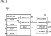
- the electric tool system 100 of the present embodiment includes the electric tool 1 and an external device C1.
- the electric tool 1 includes the housing 2, the motor 3, the holder 4, the first display 5, an operating member 6, a driver 7, a clutch 8, a control circuit 91, a communication interface 92, a second display 93, a forward reverse switch 94, a power supply connector 95, and a communication connector 96.
- the first display 5 corresponds to a display of the present invention.
- the grip 22 and the holder 4 are aligned with each other along a longitudinal direction, which will be described later, of the grip 22. That is, the electric tool 1 of the present embodiment is a vertical electric tool.
- the electric tool 1 may be a collapsible electric tool as long as it is an electric tool configured to perform the fastening operation in the state where the grip 22 and the holder 4 are aligned with each other along the longitudinal direction of the grip 22.
- the longitudinal direction of the grip 22 is defined as an up/down direction
- the holder 4 is defined to be located downward of the grip 22
- the grip 22 is defined to be located upward of the holder 4.
- the housing 2 includes a first part 21, the grip 22, the stopper 23, and the second part 24.
- the first part 21 is in the shape of a substantially rectangular parallelepiped.
- the first part 21 houses the control circuit 91 and the communication interface 92.
- the first part 21 has a surface 211 (see FIG. 1 ) and a back surface 212 (see FIG. 3 ) as two surfaces facing each other.
- the second display 93 is disposed on the surface 211.
- the grip 22 has an elongated shape and is to be gripped by a person. The worker can grip the grip 22 to perform the fastening operation.
- the grip 22 protrudes downward from a lower end of the first part 21.
- the grip 22 of the present embodiment is cylindrical.
- the grip 22 of the present embodiment houses the motor 3 and at least part of the driver 7.
- the stopper 23 is disposed at the end 221 of the grip 22.
- the end 221 is located at the side of the holder 4. That is, the stopper 23 is disposed at the end 221 at a lower side of the grip 22.
- the stopper 23 protrudes beyond the end 221 of the grip 22 in the protrusion direction intersecting the longitudinal direction (the up/down direction in FIG. 1 ) of the grip 22.
- the stopper 23 protrudes in the protrusion direction from the entire circumference of the end 221 of the grip 22.
- the stopper 23 protrudes in the protrusion direction in one round of the end 221 of the grip 22.
- the protrusion direction of the stopper 23 of the present embodiment is a direction vertical to the longitudinal direction of the grip 22.
- the stopper 23 of the present embodiment has a circularly annular shape. In the present embodiment, the stopper 23 has an outer diameter greater than an outer diameter of the grip 22.
- the second part 24 protrudes downward from a lower end of the stopper 23.
- the second part 24 is in the shape of a cylinder whose bottom has an opening 241.
- the second part 24 houses the clutch 8 and at least part of the driver 7.
- the motor 3 is housed in a lower portion of the grip 22.
- the motor 3 includes: a rotor having a rotary shaft and a permanent magnet; and a stator having a coil. Electromagnetic interaction between the permanent magnet and the coil rotates the rotor with respect to the stator. As a result, the motor 3 performs the rotation operation.
- the torque and the rotational velocity of the motor 3 change in accordance with control by the control circuit 91 (servo driver). More specifically, the control circuit 91 controls the operation of the motor 3 by feedback control of controlling such that the torque and the rotational velocity of the motor 3 approach respective target values.
- the driver 7 includes a planet gear mechanism connected to the rotary shaft of the motor 3. As a result, the driver 7 rotates in interconnection with the rotary shaft of the motor 3. That is, the driver 7 is rotated by the motor 3.
- the driver 7 is housed in the grip 22, the stopper 23, and the second part 24.
- the planet gear mechanism converts the rotational velocity and the torque of the rotary shaft of the motor 3 respectively into a rotational velocity and a torque required for the operation of turning a screw.
- the planet gear mechanism is a deceleration device.
- the torque of the rotary shaft of the motor 3 is transmitted from the planet gear mechanism to the driver 7.
- the clutch 8 When a fastening torque value of the fastening operation reaches the target value, the clutch 8 mechanically interrupts the transmission of the rotational force to the tip tool B1.
- the worker turns a dial ring (not shown) disposed on a side surface of the clutch 8, thereby manually setting the target value of the fastening torque value.
- the clutch 8 of the present embodiment disconnects a mechanical connection between the driver 7 and the holder 4.
- the "fastening torque value" is the value of torque applied to the fastening part by the tip tool B1 in the fastening operation.
- the clutch 8 is housed in the second part 24. That is, as shown in FIG. 6 , the clutch 8 is disposed between the stopper 23 and the holder 4.
- This configuration provides the effect that the distance between the holder 4 and the first display 5 to be increased. As a result, even when a part of the work target to which the fastening part is to be fastened is recessed, the first display 5 is suppressed from being hidden by the work target.
- the holder 4 holds the tip tool B1 to which the rotational force is to be transmitted from the motor 3. As shown in FIG. 4 , the holder 4 is disposed on an end surface of the clutch 8. The end surface is exposed from the opening 241 of the second part 24. That is, the holder 4 is disposed on a lower end surface of the clutch 8. The holder 4 is rotated together with the tip tool B1 by the motor 3.
- the tip tool B1 ( FIG. 1 ) is detachably and directly attached to the holder 4.
- the holder 4 may have a chuck to which the tip tool B1 is removably attached.
- the holder 4 may be integrally formed with the tip tool B1.
- the tip tool B1 is, for example, a driver bit. The holder 4 rotates in the state where the tip tool B1 is fit to the fastening part, thereby enabling an operation such as fastening or loosening the fastening part.
- the communication interface 92 communicates with a communication interface C11, which will be described later, of the external device C1.
- the communication interface 92 of the present embodiment communicates via a communication cable with the communication interface C11 of the external device C1.
- the communication interface 92 transmits, to the communication interface C11 of the external device C1, data on a motor current value which is the value of a current flowing through the motor 3. More specifically, the motor current value is the value of a current which flows through the motor 3 when the clutch 8 operates.
- the communication interface 92 of the present embodiment receives a determination result by a determiner C13 of the external device C1 from the communication interface C11 of the external device C1. That is, the communication interface 92 of the present embodiment receives, from the external device C1, the determination result as to whether or not the fastening operation has normally been performed. The communication interface 92 of the present embodiment outputs the determination result thus received to the first display 5.
- the first display 5 displays the state the fastening operation of fastening the fastening part to the work target by the tip tool B1.
- the first display 5 of the present embodiment displays whether or not the fastening operation has normally been performed. More specifically, the first display 5 of the present embodiment displays the determination result by the external device C1 as to whether or not the fastening operation has normally been performed.
- the first display 5 is disposed on the stopper 23.
- the worker gazes the fastening part or the tip tool B1 during the fastening operation. Therefore, disposing the first display 5 on the stopper 23, which is located closer to the tip tool B1 than the grip 22 is, provides the advantage that the worker can check the state of the fastening operation without widely moving his/her eyes from the fastening part or the tip tool B1 at the end of the fastening operation.
- the configuration that the first display 5 is disposed on the stopper 23 can suppress the hand of the worker gripping the grip 22 from moving toward the holder 4 and from covering the first display 5 when the worker pushes the electric tool 1 against the fastening part during the fastening operation. That is, there is also the advantage that the first display 5 can be prevented from being uncheckable.
- the first display 5 is disposed on the stopper 23 protruding in the protrusion direction intersecting the longitudinal direction of the grip 22. Therefore, even when a part of the work target to which the fastening part is to be fastened is recessed, the first display 5 is suppressed from being hidden by the work target. That is, there is the advantage that checking the state of the fastening operation is further facilitated.
- the first display 5 of the present embodiment is disposed on the entire circumference of an outer surface of the stopper 23. That is, the first display 5 of the present embodiment has a shape extending over the entire circumference of the outer surface of the stopper 23 as shown in FIGS. 1 and 3 . More specifically, the first display 5 has a shape extending one round along a circumferential direction of the outer surface of the stopper 23. In other words, the first display 5 of the present embodiment has a circularly annular shape along the circumferential direction of the outer surface of the stopper 23. This configuration provides the advantage that the worker can check the state of the fastening operation regardless of the position which the worker performing the fastening operation takes.
- the two light-emitting elements 51 each output light in a plurality of colors individually.
- each of the two light-emitting elements 51 is a color-tunable LED element.
- the transmission cover 53 transmits light output from each of the two light-emitting elements 51 to the outside of the electric tool 1. As shown in FIG. 5 , the transmission cover 53 has a circularly annular shape. The transmission cover 53 has a blasted outer surface so that light output from the light-emitting elements 51 is diffused.
- the "outer surface of the transmission cover 53" as used herein is a side surface which is one of side surfaces of the transmission cover 53 and which does not face the light-emitting elements 51. As shown in FIG. 4 , the transmission cover 53 of the present embodiment is disposed at a center part of the stopper 23 in the up/down direction.
- the holding pedestal 52 holds each of the two light-emitting elements 51.
- the two light-emitting elements 51 and the holding pedestal 52 are disposed at an upper portion of the stopper 23 in the up/down direction. That is, in the present embodiment, the two light-emitting elements 51 and the holding pedestal 52 are disposed at an upper end of the transmission cover 53.
- the holding pedestal 52 of the present embodiment is a U-shaped plate member which curves along the circumferential direction of the transmission cover 53.
- the holding pedestal 52 has a U-shaped inner edge extending along an outer perimeter of the driver 7.
- the holding pedestal 52 of the present embodiment has a lower surface 521 which is a surface facing the transmission cover 53 in the up/down direction, and the holding pedestal 52 holds the two light-emitting elements 51 on the lower surface 521. More specifically, the holding pedestal 52 holds the two light-emitting elements 51 on the lower surface 521 such that the two light-emitting elements 51 are disposed with a 180 degree-interval along the circumferential direction of the transmission cover 53. That is, the two light-emitting elements 51 are disposed along the outer perimeter of the driver 7 with an interval of 180 degrees.
- the stopper 23 has a groove 231 (see FIG. 4 ) which is located at an upper portion of an inner surface of the stopper 23 and which extends in a circumferential direction of the stopper 23. The two light-emitting elements 51 and the holding pedestal 52 are fixed to the stopper 23 by fitting an outer edge of the stopper 23 in the groove 231.
- the first display 5 switches, in accordance with the state of the fastening operation, the color of light output therefrom to any one of the plurality of colors.
- This configuration has the advantage that the worker can easily check the state of the fastening operation.
- the first display 5 of the present embodiment switches, depending on whether or not the fastening operation has normally been performed, the color of light output therefrom to any one of the plurality of colors.
- Each of the light-emitting elements 51 of the present embodiment can output green light and red light. That is, the first display 5 of the present embodiment is configured to output green light and red light. If the estimator C12 determines that the fastening operation has normally been performed, the first display 5 of the present embodiment outputs the green light. In contrast, if the estimator C12 determines that the fastening operation has not normally been performed, the first display 5 of the present embodiment outputs the red light.
- the operating member 6 is disposed on a side surface of the first part 21. More specifically, the operating member 6 is disposed to protrude downward from the side surface of the first part 21 as shown in FIGS. 1 and 3 .
- the operating member 6 receives an operation for controlling the rotation of the motor 3.
- the worker gives an operation of tilting the operating member 6 toward the grip 22, thereby switching ON/OFF of the rotation of the motor 3.
- a pulled amount of the operating member 6 indicating how much the operating member 6 is tilted can an adjust the rotational velocity of the motor 3. The greater the pulled amount is, the higher the rotational velocity of the motor 3.
- the forward reverse switch 94 is a switch for switching a rotational direction of the motor 3. As shown in FIGS. 1 and 3 , the forward reverse switch 94 of the present embodiment is disposed on a side surface which is one of side surfaces of the first part 21 and on which the operating member 6 is not disposed.
- the control circuit 91 rotates or deactivates the motor 3 or controls the rotational velocity of the motor 3 in accordance with the operation of tilting the operating member 6. Moreover, the control circuit 91 controls the rotational direction of the motor 3 in accordance with a position of the forward reverse switch 94.
- the control circuit 91 includes, for example, a microcontroller.
- the operating member 6 changes the rotational velocity of the motor 3, thereby changing the rotational velocity of the driver 7 and the tip tool B1.
- the control circuit 91 changes, for example, electric power to be supplied to the motor 3, thereby changing the rotational velocity of the motor 3.
- the second display 93 is configured to display numerical digits or alphabets. As shown in FIG. 1 , the second display 93 of the present embodiment is a 7-segment LED display. The second display 93 displays, for example, the number of fastening parts for which the fastening operation has been performed.
- the power supply connector 95 is a component to which a power supply cable is to be electrically connected. Through the power supply cable, the electric power is supplied to the electric tool 1.
- the communication connector 96 is a component to which a communication cable is to be connected. The communication cable allows the communication interface 92 of the electric tool 1 and the communication interface C11 of the external device C1 to communicate with each other.
- the power supply connector 95 and the communication connector 96 are disposed at an upper portion of the electric tool 1. More specifically, the power supply connector 95 and the communication connector 96 are disposed on an upper end surface of the first part 21 of the housing 2.
- the external device C1 is a device configured to: determine whether or not the fastening operation has normally been performed by the electric tool 1; and transmit the determination result to the electric tool 1.
- the external device C1 of the present embodiment includes the communication interface C11, an estimator C12, and the determiner C13.
- the communication interface C11 communicates with the communication interface 92 of the electric tool 1. More specifically, the communication interface C11 receives data on the motor current value transmitted from the communication interface 92 of the electric tool 1. The communication interface C11 outputs the data, thus received, on the motor current value to the estimator C12.
- the estimator C12 calculates the rotational velocity, a change in rotation amount, and the like of the motor 3. Based on a calculation result, the estimator C12 estimates the value of fastening torque which is applied to the fastening part when the clutch 8 operates. That is, the estimator C12 estimates, based on the motor current value when the clutch 8 operates, the value of the fastening torque, which is applied to the fastening part when the clutch 8 operates.
- the determiner C13 determines, based on the value of the fastening torque estimated by the estimator C12, whether or not the fastening operation has normally been performed. More specifically, the determiner C13 determines whether or not the value of the fastening torque estimated by the estimator C12 is within a set range set in advance, and if the value is within the set range, the determiner C13 determines that the fastening operation has normally been performed. In contrast, the determiner C13 determines whether or not the value of the fastening torque estimated by the estimator C12 is within the set range set in advance, and if the value is out of the set range, the determiner C13 determines that the fastening operation has not normally been performed.
- the set range is set such that the set range includes a predetermined error range from a target value of the fastening torque of the fastening operation.
- the communication interface C11 transmits the determination result by the determiner C13 to the communication interface 92 of the electric tool 1.
- the electric tool 1 starts the fastening operation (S1). More specifically, the worker tilts the operating member 6 toward the grip 22 in the state where the tip tool B1 held by the holder 4 is in contact with the fastening part, and thereby, the electric tool 1 starts the fastening operation. Then, when the fastening torque value of the fastening operation reaches the target value, the clutch 8 operates to mechanically interrupt the transmission of the rotational force to the tip tool B1 (S2). Thereafter, the worker returns the operating member 6 to a position which the operating member 6 took at a time point before a start of the fastening operation, and thereby, the electric tool 1 ends the fastening operation (S3).
- the communication interface 92 of the electric tool 1 transmits, to the communication interface C11 of the external device C1, data on the motor current value, which is the value of the current which flows through the motor 3 when the clutch 8 operates.
- the communication interface 92 of the electric tool 1 receives the determination result by the determiner C13 from the communication interface C11 of the external device C1 (S9) and outputs the determination result to the first display 5.
- the first display 5 displays the determination result by the determiner C13 (S10). That is, the first display 5 displays whether or not the fastening operation has normally been performed. Specifically, if the estimator C12 determines that the fastening operation has normally been performed, the first display 5 of the present embodiment outputs green light. In contrast, if the estimator C12 determines that the fastening operation has not normally been performed, the first display 5 of the present embodiment outputs red light.
- the first display 5 of the embodiment described above switches, in accordance with the state of the fastening operation, the color of light output therefrom to any one of the plurality of colors.
- the first display 5 may be configured to display at least one of characters, numerical digits, or symbols, and in accordance with the state of the fastening operation, the first display 5 may display at least one of the characters, the numerical digits, or the symbols.
- the first display 5 may be a liquid crystal display or an organic EL display configured to display at least one of the characters, the numerical digits, or the symbols. This configuration provides the advantage that grasping the state of the fastening operation is facilitated.
- the first display 5 may display a string of the characters such as "normal” or “OK”, or a symbol such as " ⁇ ".
- the estimator C12 determines that the fastening operation has not normally been performed, the first display 5 may display a string of the characters such as "abnormal” or "NG”, or a symbol such as " ⁇ ".
- the first display 5 may have a function of the second display 93 and may display, for example, the number of fastening parts and the like for which the fastening operation has been performed.
- the first display 5 may be configured such that the outer surface of the transmission cover 53 has holes in the shape of characters, numerical digits, or symbols, and the character(s), the numerical digit(s), or the symbol(s) emerges when the light-emitting elements 51 output light.
- the first display 5 of the embodiment described above includes the two light-emitting elements 51, the holding pedestal 52, and the transmission cover 53.
- the structure of the first display 5 is not limited.
- the first display 5 may include one or more light-emitting elements directly disposed on the outer surface of the stopper 23.
- the electric tool 1 may include, as the first display 5, a color-tunable LED element directly disposed on the outer surface of the stopper 23.
- the communication interface 92 of the embodiment described above transmits, to the communication interface C11 of the external device C1, data on the motor current value when the clutch 8 operates.
- the communication interface 92 may transmit, to the communication interface C11 of the external device C1, data on a motor current value immediately before the clutch 8 operates.
- the estimator C12 of the external device C1 estimates, based on the data on the motor current value immediately before the clutch 8 operates, the value of the fastening torque which is applied to the fastening part immediately before the clutch 8 operates.
- the communication interface 92 may transmit, to the communication interface C11 of the external device C1, data on a motor current value in a time period from when the electric tool 1 starts the fastening operation until the clutch 8 operates.
- the estimator C12 of the external device C1 estimates, based on the data on the motor current value in the time period from when the electric tool 1 starts the fastening operation until the clutch 8 operates, a maximum value of the fastening torque which is applied to the fastening part in the time period from when the electric tool 1 starts the fastening operation until the clutch 8 operates.
- An electric tool (1) of a first aspect includes a motor (3), a holder (4), a display (5), and a housing (2).
- the motor (3) is configured to perform rotation operation.
- the holder (4) is configured to hold a tip tool (B1) to which a rotational force is to be transmitted from the motor (3).
- the display (5) is configured to display a state of a fastening operation of fastening a fastening part to a work target by the tip tool (B1).
- the housing (2) houses the motor (3).
- the housing (2) includes a grip (22) and a stopper (23).
- the grip (22) has an elongated shape and is configured to be gripped by a person.
- This aspect provides the advantage that checking the state of the fastening operation is further facilitated.
- the stopper (23) protrudes in the protrusion direction from an entire circumference of the end (221).
- This aspect provides the effect that the hand of the worker is suppressed from slipping downward from the grip (22) during the fastening operation. This consequently provides the advantage that the display (5) disposed on the stopper (23) is suppressed from being hidden by the hand of the worker during the fastening operation.
- the display (5) has a shape extending over an entire circumference of an outer surface of the stopper (23).
- This aspect provides the advantage that the worker can check the state of the fastening operation regardless of the position which the worker performing the fastening operation takes.
- the display (5) is configured to display whether or not the fastening operation has normally been performed.
- This aspect provides the advantage that the worker can check whether or not the fastening operation has normally been performed.
- An electric tool (1) of a fifth aspect referring to any one of the first to fourth aspects further includes a clutch (8).
- the clutch (8) is configured to mechanically interrupt transmission of the rotational force to the tip tool (B1) when a fastening torque value of the fastening operation reaches a target value.
- the clutch (8) is disposed between the stopper (23) and the holder (4).
- This aspect provides the advantage that even when a part of the work target where the fastening part is to be fastened is recessed, the work target is suppressed from hiding the display (5).
- the display (5) is configured to output light in a plurality of colors individually.
- the display (5) is configured to switch, in accordance with the state of the fastening operation, a color of the light which the display (5) outputs to any one of the plurality of colors.
- This aspect provides the advantage that the worker can easily check the fastening operation.
- the display (5) is configured to display at least one of a character, a numerical digit, or a symbol.
- This aspect provides the advantage that grasping the state of the fastening operation is facilitated.
Landscapes
- Engineering & Computer Science (AREA)
- Mechanical Engineering (AREA)
- Details Of Spanners, Wrenches, And Screw Drivers And Accessories (AREA)
- Portable Power Tools In General (AREA)
Applications Claiming Priority (2)
| Application Number | Priority Date | Filing Date | Title |
|---|---|---|---|
| JP2022073604A JP7821033B2 (ja) | 2022-04-27 | 2022-04-27 | 電動工具 |
| PCT/JP2023/014522 WO2023210322A1 (ja) | 2022-04-27 | 2023-04-10 | 電動工具 |
Publications (2)
| Publication Number | Publication Date |
|---|---|
| EP4516455A1 true EP4516455A1 (de) | 2025-03-05 |
| EP4516455A4 EP4516455A4 (de) | 2025-08-13 |
Family
ID=88518394
Family Applications (1)
| Application Number | Title | Priority Date | Filing Date |
|---|---|---|---|
| EP23796068.7A Pending EP4516455A4 (de) | 2022-04-27 | 2023-04-10 | Elektrowerkzeug |
Country Status (4)
| Country | Link |
|---|---|
| EP (1) | EP4516455A4 (de) |
| JP (1) | JP7821033B2 (de) |
| CN (1) | CN118984761A (de) |
| WO (1) | WO2023210322A1 (de) |
Family Cites Families (7)
| Publication number | Priority date | Publication date | Assignee | Title |
|---|---|---|---|---|
| JPH0486170U (de) * | 1990-11-30 | 1992-07-27 | ||
| JP4882802B2 (ja) | 2007-03-02 | 2012-02-22 | 船井電機株式会社 | ホログラム記録装置及びホログラム再生装置 |
| JP5709087B2 (ja) | 2011-02-04 | 2015-04-30 | 日立工機株式会社 | 電動工具 |
| DE102011077440A1 (de) | 2011-06-14 | 2012-12-20 | Robert Bosch Gmbh | Handwerkzeugmaschine |
| JP5992763B2 (ja) | 2012-08-17 | 2016-09-14 | 株式会社東日製作所 | トルクドライバー |
| WO2021060015A1 (ja) | 2019-09-27 | 2021-04-01 | 日東工器株式会社 | 電動工具の制御回路、制御装置、および電動工具 |
| TWI780371B (zh) | 2019-10-29 | 2022-10-11 | 朝程工業股份有限公司 | 可感測手動操作扭力之電動扭力扳手 |
-
2022
- 2022-04-27 JP JP2022073604A patent/JP7821033B2/ja active Active
-
2023
- 2023-04-10 EP EP23796068.7A patent/EP4516455A4/de active Pending
- 2023-04-10 WO PCT/JP2023/014522 patent/WO2023210322A1/ja not_active Ceased
- 2023-04-10 CN CN202380033245.1A patent/CN118984761A/zh active Pending
Also Published As
| Publication number | Publication date |
|---|---|
| JP7821033B2 (ja) | 2026-02-26 |
| WO2023210322A1 (ja) | 2023-11-02 |
| EP4516455A4 (de) | 2025-08-13 |
| CN118984761A (zh) | 2024-11-19 |
| JP2023162896A (ja) | 2023-11-09 |
Similar Documents
| Publication | Publication Date | Title |
|---|---|---|
| US9923249B2 (en) | Rechargeable battery pack for a handheld power tool | |
| EP3552768A1 (de) | Elektrowerkzeug und verfahren zur steuerung eines elektrowerkzeugs | |
| CN108406663B (zh) | 电动工具 | |
| EP2223783B1 (de) | Licht für ein Werkzeug und Verfahren zur Werkstückbeleuchtung | |
| EP2807000B1 (de) | Tragbare schnurlose elektrowerkzeuge für präzisionsfixierung | |
| EP2576146B1 (de) | Angetriebenes werkzeug | |
| CN111421511A (zh) | 电动工具 | |
| JP5354363B2 (ja) | 電動工具 | |
| US20180215029A1 (en) | Quick double trigger configuration change | |
| EP4177018A1 (de) | Kopplung und entkopplung eines hauptgehäuses und eines funktionalen aufsatzes einer handgehaltenen körperpflegevorrichtung | |
| US10780565B2 (en) | Housing device for a hand-held power tool | |
| JP5206084B2 (ja) | 電動工具 | |
| JP2012254519A (ja) | 電動工具及び電動工具用の通信プラグ | |
| EP4144483A1 (de) | Arbeitsmaschine | |
| EP3427900B1 (de) | Werkzeugmaschine mit einer mit werkzeugarbeitsgeräten koppelbaren werkzeugmaschinenbasis | |
| CN107666195B (zh) | 电动工具用电机中的绕组的形成方法和电动工具 | |
| EP4516455A1 (de) | Elektrowerkzeug | |
| CN214175954U (zh) | 断路器 | |
| CN103230230A (zh) | 手持式搅拌棒及其处理方法 | |
| KR20160001373A (ko) | 프리전압 구동을 위한 전동공구의 제어장치 | |
| EP3352324A1 (de) | Ladeadapter für zwei akkus | |
| CN109571205B (zh) | 一种动力机构及角磨机 | |
| KR101770574B1 (ko) | 회전방향 조절 기능이 구비된 의료용 드릴장치 | |
| CN210246640U (zh) | 一种三相电输入稳定型固态继电器模块 | |
| CN112542359A (zh) | 断路器 |
Legal Events
| Date | Code | Title | Description |
|---|---|---|---|
| STAA | Information on the status of an ep patent application or granted ep patent |
Free format text: STATUS: THE INTERNATIONAL PUBLICATION HAS BEEN MADE |
|
| PUAI | Public reference made under article 153(3) epc to a published international application that has entered the european phase |
Free format text: ORIGINAL CODE: 0009012 |
|
| STAA | Information on the status of an ep patent application or granted ep patent |
Free format text: STATUS: REQUEST FOR EXAMINATION WAS MADE |
|
| 17P | Request for examination filed |
Effective date: 20241031 |
|
| AK | Designated contracting states |
Kind code of ref document: A1 Designated state(s): AL AT BE BG CH CY CZ DE DK EE ES FI FR GB GR HR HU IE IS IT LI LT LU LV MC ME MK MT NL NO PL PT RO RS SE SI SK SM TR |
|
| DAV | Request for validation of the european patent (deleted) | ||
| DAX | Request for extension of the european patent (deleted) | ||
| A4 | Supplementary search report drawn up and despatched |
Effective date: 20250716 |
|
| RIC1 | Information provided on ipc code assigned before grant |
Ipc: B25B 23/14 20060101AFI20250710BHEP Ipc: B25B 23/157 20060101ALI20250710BHEP Ipc: B25F 5/00 20060101ALI20250710BHEP Ipc: B25F 5/02 20060101ALI20250710BHEP Ipc: B25B 21/00 20060101ALI20250710BHEP |