EP4516237A2 - Injizierbare hämodynamische überwachungssysteme - Google Patents
Injizierbare hämodynamische überwachungssysteme Download PDFInfo
- Publication number
- EP4516237A2 EP4516237A2 EP24213455.9A EP24213455A EP4516237A2 EP 4516237 A2 EP4516237 A2 EP 4516237A2 EP 24213455 A EP24213455 A EP 24213455A EP 4516237 A2 EP4516237 A2 EP 4516237A2
- Authority
- EP
- European Patent Office
- Prior art keywords
- sensor
- data
- data stream
- blood vessel
- patient
- Prior art date
- Legal status (The legal status is an assumption and is not a legal conclusion. Google has not performed a legal analysis and makes no representation as to the accuracy of the status listed.)
- Pending
Links
Images


Classifications
-
- A—HUMAN NECESSITIES
- A61—MEDICAL OR VETERINARY SCIENCE; HYGIENE
- A61B—DIAGNOSIS; SURGERY; IDENTIFICATION
- A61B8/00—Diagnosis using ultrasonic, sonic or infrasonic waves
- A61B8/12—Diagnosis using ultrasonic, sonic or infrasonic waves in body cavities or body tracts, e.g. by using catheters
-
- A—HUMAN NECESSITIES
- A61—MEDICAL OR VETERINARY SCIENCE; HYGIENE
- A61B—DIAGNOSIS; SURGERY; IDENTIFICATION
- A61B17/00—Surgical instruments, devices or methods
- A61B17/34—Trocars; Puncturing needles
- A61B17/3468—Trocars; Puncturing needles for implanting or removing devices, e.g. prostheses, implants, seeds, wires
-
- A—HUMAN NECESSITIES
- A61—MEDICAL OR VETERINARY SCIENCE; HYGIENE
- A61B—DIAGNOSIS; SURGERY; IDENTIFICATION
- A61B8/00—Diagnosis using ultrasonic, sonic or infrasonic waves
- A61B8/02—Measuring pulse or heart rate
-
- A—HUMAN NECESSITIES
- A61—MEDICAL OR VETERINARY SCIENCE; HYGIENE
- A61B—DIAGNOSIS; SURGERY; IDENTIFICATION
- A61B8/00—Diagnosis using ultrasonic, sonic or infrasonic waves
- A61B8/04—Measuring blood pressure
-
- A—HUMAN NECESSITIES
- A61—MEDICAL OR VETERINARY SCIENCE; HYGIENE
- A61B—DIAGNOSIS; SURGERY; IDENTIFICATION
- A61B8/00—Diagnosis using ultrasonic, sonic or infrasonic waves
- A61B8/08—Clinical applications
- A61B8/0891—Clinical applications for diagnosis of blood vessels
-
- A—HUMAN NECESSITIES
- A61—MEDICAL OR VETERINARY SCIENCE; HYGIENE
- A61B—DIAGNOSIS; SURGERY; IDENTIFICATION
- A61B8/00—Diagnosis using ultrasonic, sonic or infrasonic waves
- A61B8/42—Details of probe positioning or probe attachment to the patient
- A61B8/4209—Details of probe positioning or probe attachment to the patient by using holders, e.g. positioning frames
-
- A—HUMAN NECESSITIES
- A61—MEDICAL OR VETERINARY SCIENCE; HYGIENE
- A61B—DIAGNOSIS; SURGERY; IDENTIFICATION
- A61B8/00—Diagnosis using ultrasonic, sonic or infrasonic waves
- A61B8/44—Constructional features of the ultrasonic, sonic or infrasonic diagnostic device
- A61B8/4444—Constructional features of the ultrasonic, sonic or infrasonic diagnostic device related to the probe
- A61B8/4472—Wireless probes
-
- A—HUMAN NECESSITIES
- A61—MEDICAL OR VETERINARY SCIENCE; HYGIENE
- A61B—DIAGNOSIS; SURGERY; IDENTIFICATION
- A61B8/00—Diagnosis using ultrasonic, sonic or infrasonic waves
- A61B8/44—Constructional features of the ultrasonic, sonic or infrasonic diagnostic device
- A61B8/4477—Constructional features of the ultrasonic, sonic or infrasonic diagnostic device using several separate ultrasound transducers or probes
-
- A—HUMAN NECESSITIES
- A61—MEDICAL OR VETERINARY SCIENCE; HYGIENE
- A61B—DIAGNOSIS; SURGERY; IDENTIFICATION
- A61B8/00—Diagnosis using ultrasonic, sonic or infrasonic waves
- A61B8/52—Devices using data or image processing specially adapted for diagnosis using ultrasonic, sonic or infrasonic waves
- A61B8/5207—Devices using data or image processing specially adapted for diagnosis using ultrasonic, sonic or infrasonic waves involving processing of raw data to produce diagnostic data, e.g. for generating an image
-
- A—HUMAN NECESSITIES
- A61—MEDICAL OR VETERINARY SCIENCE; HYGIENE
- A61B—DIAGNOSIS; SURGERY; IDENTIFICATION
- A61B8/00—Diagnosis using ultrasonic, sonic or infrasonic waves
- A61B8/52—Devices using data or image processing specially adapted for diagnosis using ultrasonic, sonic or infrasonic waves
- A61B8/5215—Devices using data or image processing specially adapted for diagnosis using ultrasonic, sonic or infrasonic waves involving processing of medical diagnostic data
- A61B8/5223—Devices using data or image processing specially adapted for diagnosis using ultrasonic, sonic or infrasonic waves involving processing of medical diagnostic data for extracting a diagnostic or physiological parameter from medical diagnostic data
-
- A—HUMAN NECESSITIES
- A61—MEDICAL OR VETERINARY SCIENCE; HYGIENE
- A61B—DIAGNOSIS; SURGERY; IDENTIFICATION
- A61B8/00—Diagnosis using ultrasonic, sonic or infrasonic waves
- A61B8/52—Devices using data or image processing specially adapted for diagnosis using ultrasonic, sonic or infrasonic waves
- A61B8/5269—Devices using data or image processing specially adapted for diagnosis using ultrasonic, sonic or infrasonic waves involving detection or reduction of artifacts
- A61B8/5276—Devices using data or image processing specially adapted for diagnosis using ultrasonic, sonic or infrasonic waves involving detection or reduction of artifacts due to motion
-
- A—HUMAN NECESSITIES
- A61—MEDICAL OR VETERINARY SCIENCE; HYGIENE
- A61B—DIAGNOSIS; SURGERY; IDENTIFICATION
- A61B8/00—Diagnosis using ultrasonic, sonic or infrasonic waves
- A61B8/56—Details of data transmission or power supply
- A61B8/565—Details of data transmission or power supply involving data transmission via a network
-
- A—HUMAN NECESSITIES
- A61—MEDICAL OR VETERINARY SCIENCE; HYGIENE
- A61B—DIAGNOSIS; SURGERY; IDENTIFICATION
- A61B2562/00—Details of sensors; Constructional details of sensor housings or probes; Accessories for sensors
- A61B2562/02—Details of sensors specially adapted for in-vivo measurements
- A61B2562/0219—Inertial sensors, e.g. accelerometers, gyroscopes, tilt switches
-
- A—HUMAN NECESSITIES
- A61—MEDICAL OR VETERINARY SCIENCE; HYGIENE
- A61B—DIAGNOSIS; SURGERY; IDENTIFICATION
- A61B2562/00—Details of sensors; Constructional details of sensor housings or probes; Accessories for sensors
- A61B2562/02—Details of sensors specially adapted for in-vivo measurements
- A61B2562/0271—Thermal or temperature sensors
-
- A—HUMAN NECESSITIES
- A61—MEDICAL OR VETERINARY SCIENCE; HYGIENE
- A61B—DIAGNOSIS; SURGERY; IDENTIFICATION
- A61B2562/00—Details of sensors; Constructional details of sensor housings or probes; Accessories for sensors
- A61B2562/02—Details of sensors specially adapted for in-vivo measurements
- A61B2562/028—Microscale sensors, e.g. electromechanical sensors [MEMS]
Definitions
- the present disclosure generally relates to the field of miniaturized implantable vital signs monitoring devices and methods.
- the present disclosure is directed to subcutaneously injectable blood pressure monitoring systems and methods suitable, inter alia, for long-term monitoring of cardiovascular signals.
- Hypertension is a significant precursor to cardiovascular disease and death. It is estimated that there are 1.6 billion people worldwide with hypertension, over 100 million in the United States alone, and less than one-third are under control. Hypertension is costly and deadly. There are an estimated 7.8 million deaths each year due to hypertension, and it costs the United States an estimated $131 billion annually due to lost productivity and healthcare costs. Due to its deadliness and costs, it has been a target of government, academic, for-profit, and non-profit organizations. A recent task force has been formed to help reduce the incidence and prevalence of hypertension.
- ABPM Ambulatory Blood Pressure Monitoring
- the present disclosure is directed to a hemodynamic sensor system.
- the system includes a sensor implant, comprising a housing configured and dimensioned to be delivered subcutaneously through a hollow introducer sheath into tissue adjacent a target blood vessel in a patient, and at least one tissue fixation feature on an outer surface of the housing, the sensor implant further comprising within the housing: at least one sensor modules configured to detect changes in one or more physiological parameters indicative of patient hemodynamic condition, wherein at least one the sensor module comprises an ultrasound transducer; and a communication module communicating with the at least one sensor module to transmit one or more signals comprising signals representative of the detected changes to an external receiver.
- Embodiments of the present disclosure provide unobtrusive, minimally invasive, active implantable sensor devices, sensor systems and methods that meet current clinical needs.
- Disclosed devices, systems and methods use one or more micro-electrical mechanical system (MEMS) sensors for the accurate and continuous measurement of physiological hemodynamic signals such as diastolic and systolic blood pressure.
- MEMS micro-electrical mechanical system
- embodiments disclosed herein may include any, or all, of the following additional clinical signals of overall patient status: heart rate, activity level (patient movement or position), temperature, heart rate variability, and stenosis.
- Disclosed embodiments can provide a long-term sensor system will provide accurate (equivalent to current standard of care) blood pressure over an extended duration (for instance, months or years), enabling the clinician to provide appropriate treatment recommendations.
- MEMS microelectromechanical systems
- MEMS-based-sensor module that incorporates one or more of sensors (strain/piezoelectric resistive transducer, piezoelectric/capacitive ultrasound); biocompatible nano-coatings to minimize encapsulation/biofouling; and ability to continuously capture and store cardiovascular signals for an extended duration.
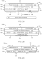
- components of a basic system 100 may comprise injectable sensor implant 102, injection device 104, local control module 106, network-based analytics and data management modules 108 and clinician module 110 comprising user interfaces/applications for data access, analysis and alerts.
- Local control module 106 may take a variety of forms.
- module 106 may comprise simply a communications module, facilitating communication between sensor implant 102 and network-based modules 108 and/or clinician module 110.
- local module in addition to a communications sub-module, local module may include processing and/or data storage sub-modules configured to store patient data from sensor implant 102 and/or determine patient parameters, such as blood pressure and fluid status, as described herein below.
- Module 106 also may function as an edge device for communication with network-based analytics, storage and data management modules.
- Module 106 thus may comprise one or more processors, memories and associated computing components commensurate with the functionality of module 106 in a specific configuration as may be devised by persons skilled in the art based on the teachings of the present disclosure.
- local control module 106 may comprise a personal mobile device, such as a cell phone or tablet, running an downloadable app.
- Clinician module 110 may comprise wirelessly connected devices such as computers, cell phones or tablets. Clinician module 110 also may be configured as a patient interface. In some embodiments, particularly where configured as a patient interface, module 110 may comprise an app running on the same device as running an app for local module 106. In some embodiments, the functionality of both modules 106 and 110 may be incorporated into a single app executed on a mobile device.
- Wireless communication links 112a and 112b are provided between sensor 102, local module 106 and network-based analytics or data management modules 108.
- Communication link l 12b also may comprise a wired communication link.
- Communication links 113 between local module 106 and user interfaces 110 may be wired or wireless.
- clinician module 110 may communicate directly with network-based analytics module 108.
- Communication links l 12a, l 12b and 113 may comprise any of a number of known communication protocols.
- communication link l 12a may comprise a personal area network (PAN) using communications based on technologies such as IrDA, Wireless USB, Bluetooth or ZigBee.
- Communication links l 12b, 113 may comprise longer range, larger bandwidth communications such as LAN, WLAN or IAN.
- one or more sensor implants 102 may communicate wirelessly with other sensor types of sensor modules via a body area network (BAN).
- BAN body area network
- sensor implants 102 may generally comprise a layered MEMS structure with typically three functional layers made up of functional modules and sub-modules: power supply and communication layer 114 comprising elements such as a primary cell batteries conventionally used to power micro-sized medical implants or, in some embodiments, a solid state lithium ion rechargeable battery and RF antenna for charging and communication, ASIC and memory layer 116 comprising amplifiers, filters, processing and memory storage, and sensor layer 118 comprising one or more sensor modules, which may comprise piezoelectric micromachined ultrasonic transducers (pMUT) or capacitive micromachined ultrasonic transducers (cMUT). In some embodiments, capacitive pressure sensing may be employed.
- power supply and communication layer 114 comprising elements such as a primary cell batteries conventionally used to power micro-sized medical implants or, in some embodiments, a solid state lithium ion rechargeable battery and RF antenna for charging and communication
- ASIC and memory layer 116 comprising amplifiers, filters, processing and memory storage
- sensor layer 118
- sensing modules may be configured as patient status sensors with additional sensing capabilities as described herein below.
- Functional layers 114, 116 and 118, together comprise a sensor package contained within a biocompatible housing 120.
- power supply and communication layer 114 may be configured for inductive coupling for charging and/or communications.
- FIGS. 2A, 2B and 2C illustrate a number of alternative configurations for sensor implant 102 that achieve these advantages.
- Sensor implant 102a includes power module 121 and communications module 122 in functional layer 114.
- the power module 121 and communications module 122 may be integrated as a single communications/power source module.
- Control and signal processing module 123 resides in functional layer 116.
- MUT sensor array 124, along with status sensor module 130 and optional acoustic lens 125 comprise sensor layer 118.
- This layered MEMS structure is contained within biocompatible housing 120.
- housing 120 may comprise rigid materials such as titanium, stainless steel or nitinol. Biocompatible plastics or silicone also may be used as a housing material.
- US transmissive window(s) 127 may be provided aligned with US sensor array 124, such that housing 120 may comprise non-US transmissive portions 126 and transmissive portions 127.
- Materials for US transmissive window(s) 127 include biocompatible materials such as polydimethylsiloxane (PDMS), silicone, glass, ceramic or parylene coatings
- Outer surfaces of housing 126 may be provided with a coating of materials to promote tissue adhesion, such as collagen, fibrin, chitosan, hyaluronic acid, and alginate, and/or may have textured, roughened or featured surfaces for this purpose.
- Other surfaces such as US transmissive windows 127, may have coatings to prevent tissue adhesion.
- adhesion preventative coatings include polymer brushes and self-assembled monolayers.
- fixation features 128 may comprise three-dimensional surface irregularities designed to create friction and prevent device migration over time. These irregularities may be rigid structures or compliant structures, such as fabric mesh or loops.
- retractable tines with memory and flexibility are optimally placed to promote stable implant position over time.
- Fixation tines are collapsible and are collapsed inside of an insertion tool and engage when released from the insertion tool.
- one or more wings, or flaps are optimally placed to promote stable implant position over time, and may be configured to collapse when inside the insertion tool and engage when released from the insertion tool.
- fixation features 128 also may be configured as antennas as a part of communications module 122.
- Sensor implants 102 also may include an attachment and release feature 129 on an outer surface of housing 126. Attachment and release feature 129 may comprise a loop or recess that is releasably engageable by a delivery and retrieval mechanism as described in more detail below.
- extravascular sensor implants are preferably positioned at a known distance from the outer wall of the blood vessel (BV) to be interrogated.
- BV blood vessel
- Optimum placement distance from the blood vessel may be set by persons of ordinary skill based on the teachings of the present disclosure taking into account parameters such as a sensor array configuration, tuning of the US signal using system electronics and selection of an acoustic lens.
- An advantage of injection devices 104 hereinafter described is that they allow for precise placement at a preferred sensing distance using visualization such as external ultrasound visualization.
- sensing distance from the blood vessel outer wall will be in the range of about 2 mm to about 50 mm. In other embodiments, a narrower distance range of about 3 mm to about 15 mm may be preferable and, in some cases, a placement of 5 mm to 7 mm may be ideal.
- FIG. 2C illustrates a further alternative embodiment, including multiple (NI through Nn) sensor arrays 124, wherein sensor implant 102c is entirely a flexible construction including housing 120 being made of flexible material that also permits US signal transmission and communication signal transmission from communication module 122.
- a housing material includes certain polymers and ceramic.
- Flexible functional layers 114, 116 and 118 may be fabricated using carbon nanotubes or ultrathin silicon integrated circuit technologies.
- FIG. 2C also illustrates a further alternative fixation feature 128, in the form of micro hooks.
- Such hooks may be comprised of resilient materials such as nitinol wire or biocompatible fabrics formed as hooks of hook and loop fasteners material.
- Embodiments of sensor implants disclosed herein are physically arranged in a manner to promote accurate readings regardless of migration or changes in orientation after implantation. This will include a combination of unique sensor fabrication that physically orients transducers in a fashion that will maintain focus on vessel of interest regardless of modest migration or movement of sensor away from vessel of interest. Aspects of this physical arrangement include the elongated configuration of housing 126 with plural spaced-apart sensor arrays 124 positioned on one side of the sensor implant, with appropriately positioned fixation features 128.
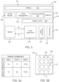
- FIG. 3 presents a representative block diagram of major functional blocks within embodiments of implant sensors 102 as disclosed herein.
- power module 121 provides a power source in the form of a power supply comprising battery 131 and power management sub-module 132.
- the battery can be generalized to any suitable implantable primary cell or rechargeable power source as may be devised by persons of ordinary skill.
- Power management sub-module 132 is configured for battery optimization to power US wireless communication, etc., with no required patient interaction to power the device, which is a substantial improvement over prior devices. Long-term monitoring can be achieved through the application of algorithms that reduce power consumption during idle times and optimize overall battery consumption, including detecting power requirements and automatedly switching appropriate modules or sub-modules to "power off' mode when power is not required in those modules or sub-modules.
- Communications module 122 comprises a transceiver sub-module configured for the selected communications mode and corresponding antenna, which is preferably positioned opposite the sensor modules at or through housing 120.
- the antenna may comprise fixation features 128 (e.g., FIGS. 2A-C ).
- Control and signal processing module 123 may comprise memory 133, digital control 134, transmit and receive electronics sub-module 135, data converter 137 and processing sub-module 136 including at least one microprocessor. These components may be configured by persons skilled in the art based on the teachings contained herein. As will be appreciated, sensor integration with ASIC provides efficiency gains in power and size by integrating the MEMS sensor into the ASIC design.
- FIG. 3A illustrates sensor array state configurations.
- sensor implant I 02c shown in FIG. 2C
- each additional sensor array its operation state during use (Tx or Rx) is flexible.
- Tx or Rx a configuration where Sensor NI and Sensor N2 are present is shown in FIG. 3A , wherein each sensor array has options of receive, transmit and active switching between receive and transmit.
- Sensor state is programmable via electronics sub-module 135.
- sensor module 124 comprises substrate 138 with an array of sensor elements 139.
- the array parameters, Ds (sensor element diameter), Hs (array height) and Ls (array length) are optimized for performance within a specific sensor implant and system.
- Ds is preferably selected based at least in part on a desired frequency of operation, thus defining a minimum vessel diameter change that can be detected by the sensor implant.
- Hs and Ls define number of sensor elements and are selected at least in part to optimize signal-to-noise ratio (SNR) as the pulse echo amplitude is defined by these parameters.
- SNR signal-to-noise ratio
- Sensor array size can also be selected in combination with the number of plural sensor modules (as in, for example, sensor implant 102c ( FIG. 2C ) in order to facilitate position identification and compensation as discussed below.
- a preferred material for sensor array 138/139 is aluminium nitride (AlN), which provides US power-efficient and biocompatible sensor array substrate compatible with human implantation.
- AlN aluminium nitride
- Previous lead-based ultrasound transducers require 1OOx more energy to power sensor and are also not biocompatible for implantable use in living beings. Further details of MUT sensor constructs suitable for use in sensor implants according to the present disclosure can be found, for example, in U.S. Patent No.
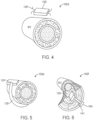
- sensor implant 102d comprises housing 120 containing a sensor package as described in various embodiments above.
- Sensor implant 102d includes tissue-engaging tines as fixation features 128 for securing the implant in proximity to blood vessel (BV) within which measurements are to be made.
- Tissue-engaging tines as fixation features 128 may be configured to engage and anchor in tissues such as muscle tissue, skin tissue, outer layers of the blood vessel itself or other suitable tissues in sufficient proximity to the vessel in which measurements are to be made.
- the tines may have barbs or other retention features (not shown) to increase the anchoring function.
- sensor implant 102f comprises housing 120 with fixation feature 128 comprised of anchor element 140 disposed on the end of flexible member 141 extending from the sensor housing.
- housing 120 of sensor implant 102f may be disposed on the inside of the blood vessel (BV) with flexible member 141 extending through the blood vessel wall, capped with anchor element 140.
- BV blood vessel
- Sensor implant 102f may be placed with instrumentation and procedures as used for vascular electrode placement or for certain vascular closure devices having anchor member placed within the vascular lumen.
- FIG. 7 shows deployment may be accomplished with alternative injection device 104a, including an outer sheath 142 with a sharpened, needle-like distal end terminating in a shovel-like protective extension 143.
- Injection device 104a otherwise may in general be configured similar to a larger-sized syringe device, wherein only the distal end portion is shown in FIG. 7 .
- Outer sheath 142 is inserted through tissue such that protective shovel portion 143 is disposed at the intended deployment site.
- Tether 144 serves as both a pusher and retrieval member for deployment of sensor 102d including anchoring tines as shown in FIG. 4 .
- tether 144 When the distal end of injection device 104a is properly positioned, tether 144 is used to move sensor 102d to an exposed position over shovel-like extension 143. This allows the tines forming fixation feature 128 of sensor 102d to engage overlying tissue while protecting the blood vessel disposed below shovel-like projection 143. Tether 144 may then be disengaged and with the tines of sensor 102d engaged on overlying tissue, injection device 104a may be withdrawn. Alternatively, if positioning is not as desired, tether 144 may be used to draw sensor 102d back within sheath 142 for repositioning. Tether 144 may engage with attachment and release feature 129 as previously described. Outer sheath 142, shown in FIG. 7 with a slight distal bend, may alternatively be straight.
- FIGS. 8 , 8A-C and 9 illustrate an embodiment of injection device 150, configured for delivering an injectable sensor such as sensor 102e ( FIG. 5 ) utilizing a resilient cuff as a passive fixation feature 128.
- Injection device 150 is configured generally as a syringe-type device with an outer introducer 152 surrounding an inner sheath 154 having a resiliently curved distal tip.
- Device injector 156 e.g. a pusher
- the release mechanism may comprise pull wire 158 ( FIG. 8B ).
- inner sheath 154 is extended and its resilient curvature causes it to wrap around the BV at the site of interest as shown in FIGS. 8C and 9 .
- Device injector 156 is used to position or maintain sensor 102e at the distal end of inner sheath 154 as it surrounds the blood vessel.
- inner sheath 154 may be withdrawn to expose sensor 102e as in FIG. 9 .
- Resilient anchor cuff 128 then surrounds the blood vessel (BV) while still secured to device injector 156 by retrieval mechanism hook 157.
- position may be confirmed by visualization such as by ultrasound or fluoroscopy.
- hook 157 may be disengaged by pulling release wire 158.
- atraumatic passive ball 160 may be disposed on the end of cuff 128 opposite sensor housing 120.
- Anchor cuff 128 may be made of resilient, shape-memory materials such as nitinol.
- FIGS. 10 , lOA and lOB illustrate a further alternative injection device 170 suitable for placement of a number of different sensor implants 102 at monitoring locations in tissue adjacent to targeted blood vessels according to the present disclosure.
- injection device 170 comprises outer introducer 172 with a sharpened, needle or syringe-like distal end, an inner atraumatic curved sheath 174 and device injector 176 sliding within inner sheath 174.
- Injection device 170 is also generally configured as a syringe-type device.
- introducer 172 is positioned subcutaneously at the desired location, preferably under visualization, such as with ultrasound.
- inner sheath 174 is advanced out of the distal end of introducer 172.
- Atraumatic distal end of inner sheath 174 facilitates positioning in close proximity to a blood vessel of interest while minimizing possibility of trauma to the blood vessel during the sensor injection procedure.
- Distal end of inner sheath 174 may have a pre-set curve as shown in FIGS. lOA and lOB such that after exiting outer introducer the inner sheath automatically assumes the pre-set curvature thereby facilitating placement with reduced risk of trauma to the adjacent blood vessel.
- sensor 102 is advanced out of the distal end by device injector 176.
- the distal end of device injector 176 may be provided with a retrieval mechanism such as a hook as described herein. After position of sensor 102 and engagement of the fixation feature is confirmed, inner sheath 174 may be withdrawn and then the sensor disengaged from device injector 176. Injection device 170 as a whole is then withdrawn.
- a retrieval mechanism such as a hook as described herein.
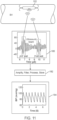
- FIG. 11 illustrates the use of MEMS ultrasound in sensor implant 102 to determine blood pressure and other vitals based on pulse transit time and pulse wave velocity measurements 180, which are amplified, filtered and processed 182 to provide a data stream from which blood pressure over time 184 may be calculated according to known correlations between blood pressure and pulse wave velocity.
- Ultrasound is the transmission of sound waves through a medium. When the ultrasound sound waves reach a surface or differing medium, the wave reflects and travels back in the originating direction. The time it takes for the ultrasound wave to travel can be used to calculate the distance from the reflecting surface.
- This ultrasound concept may be used in embodiments of the present disclosure to calculate the diameter of the vessel wall and can be used to estimate volumetric changes in the vessel as a pulse wave travels through the vessel. Based on the wave transmission and properties, the ability to differentiate the variability in reflecting mediums, such as hard plaque or wall stiffness, is also possible.
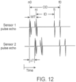
- vessel dimensions as well as PWV can be determined as illustrated in FIG. 12 .
- vessel dimensions as well as PWV can be determined as illustrated in FIG. 12 .
- four separate US pulses can be defined, representing the outer surface of the near (proximal) wall, the inner surface of the near (proximal) wall, the inner surface of the far (distal) wall, and the outer surface of the far (distal) wall. This allows determination of not only the diameter of the inner vessel, but also the thickness of the arterial wall. Heart rate is also directly determinable from this signal over time.
- Table 1 sets forth the parameters identified in FIG. 12 . Table 1- FIG.
- FIG. 13 depicts an embodiment of a process flow for determination of patient blood pressure and general hemodynamic state.
- Placement of sensor implants 102 according to the present disclosure as described above may be performed as an in- or outpatient procedure, employing clinically accepted practices for subcutaneous insertion.
- Typical placement sites include the upper arm targeting the brachial artery for monitoring, or the thoracic region targeting the subclavian artery in the delta pectoral groove for monitoring.
- patient diastolic blood pressure is measured and input to the system, for example via interface 110 (step 186).
- Other patient data may be input at this time to improve accuracy of hemodynamic state assessment.
- Such other information may include patient age, sex, weight, height and any known comorbidities.
- the system is initialized (step 187).
- monitoring begins with US sensor modules 124 and status sensor module 130 (step 188).
- body position or changes in body position are detected (step 188) with an accelerometer included in status sensor module 130 to permit adjustment of the calculated blood pressure to take into account variations based on body position and movement.
- Sensor module operation may be programmed on an intermittent basis at specific periods or may be continuous or near-continuous.
- US pulse echo signals are received (step 189) initially by electronics sub-module 135 for processing in control and signal processing module 123.
- processing at this point may be minimal, such as filtering and signal amplification, with the signal data thereafter transmitted via communications module for further signal processing in external module 106 or in other networked processing environments such as network-based systems 108 or a computing system associated with user interface 110.
- further signal as described in the following steps 190-194 is executed within control and signal processing module 123 of sensor implant 102 according to instructions stored in memory sub-module 133.
- envelope detection step 190
- region-of-interest detection step 191
- peak detection step 192
- envelope detection step 190
- region-of-interest detection step 191
- peak detection step 192
- signal-processing algorithms for processing of US signals.
- signal data appropriately processed for interpretation by the designated computing device (internal, external or networked)
- vessel diameter as a function of time is determined based on analysis of the US signals (step 193).
- Measured and recorded data stored in memory module 133 may include, for example, vessel inner and outer diameters at each US sensor array, L'.1T between the different US sensor array readings, heart rate/interval, temperature and patient or sensor implant orientation.
- Pulse wave velocity is determined and recorded at step 194 based on parameters determined in prior steps. Based on determined PWV and at least the previously measured and entered Diastole BP (step 186), blood pressure is calculated (step 195), according to correlations known in the art, for example, using algorithms described by Ma et al. as explained above. Additional inputs to blood pressure calculation (step 195), which may increase accuracy of the calculated blood pressure, may include other measured parameters (step 188) such as patient activity or orientation (as determined by accelerometer or IMU in status sensor module 130) and body temperature (as determined by temperature sensor in module 130). Other parameters as described hereinabove also may be factored in by persons of ordinary skill based on the teachings of the present disclosure.
- Patient blood pressure and other hemodynamic parameters as measured and determined, along with measured parameters are delivered to the clinician/patient interface, such as interface 110 (step 196).
- calculation of blood pressure is executed in network-based systems through appropriate network connections with local control module 106.
- FIG. 14 illustrates a further alternative embodiment of a system 1OOa according to the present disclosure.
- sensor implant 102 includes at least two ultrasound sensor modules comprised of micromachined ultrasonic transducer arrays, a status sensor module comprised of at least an accelerometer, and a control module including at least one microprocessor and at least one memory containing instructions and configured to allow the sensor implant to perform at least sensing and processing steps 188 through 193.
- communication module 122 uses Bluetooth communication to transmit a processed data stream containing blood vessel dimension, timing and accelerometer information as needed to permit calculation of pulse wave velocity and patient blood pressure.
- Parameters utilized in processing may include those parameters that are determined during initial implantation of implant sensor 102 and as may be updated as needed with periodic calibration.
- periodic calibration may include analysis to determine placement relative to initial placement location.
- analysis of returned US signals allows for continually accurate PWV calculation by using changes in the US-viewed orientation relative to the observed vascular structure to determine a skew factor for correcting PWV calculations.
- the system may determine that the longitudinal axis of the sensor implant, originally preferably implanted in alignment with direction of blood flow or at a known orientation with respect thereto, has become skewed relative to flow direction by a determined skew angle.
- devices, systems and methods disclosed herein given the large and varied amount of physiological and specifically hemodynamic data generated, allow for accurate detection and classification of arrythmias, such as bradycardia, ventricular tachy-cardia, atrial fibrillation, atrial tachycardia, and sinus pause using data generated in accordance with the teaching of the present disclosure in known diagnostic algorithms.
- arrythmias such as bradycardia, ventricular tachy-cardia, atrial fibrillation, atrial tachycardia, and sinus pause
- one or more of the following vital signals systolic BP, diastolic BP, mean arterial BP, Pulse Wave Velocity (PWV), blood flow, arterial stiffness, elasticity modulus, ECG waveform, heart rate, heart rhythm, atrial fibrillation, bradycardia, tachycardia, sinus pause, activity, body position, blood pressure variability, heart rate variability, endothelial function, coronary artery disease, blood oxygen saturation (02 sat), composite score or indication of cardiovascular health and risk may be calculated, stored and uploaded to network-based systems for accurate patient assessments over extended times without requiring in-patient or clinic visits for data collection.
- patient-centered engagement apps employing user interfaces on mobile devices or home computing devices to encourage adherence and patient behaviors may be driven based on collected data and analysis thereof.
- various aspects of the present disclosure may be executed as one or more computing devices 200 as illustrated in FIG. 15 .
- computing device 200 includes one or more processors 202, memory 204, storage device 206, high-speed interface 208 connecting to memory 204 and high-speed expansion ports 210, and a low speed interface 212 connecting to low speed bus 214 and storage device 206.
- Each of the components 202, 204, 206, 208, 210, and 212 are interconnected using various busses or other suitable connections as indicated in FIG. 15 by arrows connecting components.
- Processor 202 can process instructions for execution within the computing device 200, including instructions stored in the memory 204 or on the storage device 206 to display graphical information via GUI 218 with display 220, or on an external user interface device, coupled to high speed interface 208.
- multiple processors and/or multiple busses may be used, as appropriate, along with multiple memories and types of memory.
- multiple computing devices 200 may be connected, with each device providing portions of the necessary operations (e.g., as a server bank, a group of blade servers, or a multi-processor system).
- Memory 204 stores information within the computing device 200.
- the memory 204 is a computer-readable medium.
- the memory 204 is a volatile memory unit or units.
- the memory 204 is a non-volatile memory unit or units.
- Memory within implant 102 may store, for example data from ultrasound readings representing vessel dimensions and sensor timing and patient movement based on accelerometer data. Such data also may comprise a data stream communicated from the sensor implant computing device and may be stored in a network-based memory along with pulse wave velocity and blood pressure calculations executed in a network-based computing device
- Storage device 206 is capable of providing mass storage for the computing device 200, and may contain information such as the database of tile display information described hereinabove.
- storage device 206 is a computer-readable medium.
- storage device 206 may be a floppy disk device, a hard disk device, an optical disk device, or a tape device, a flash memory or other similar solid state memory device, or an array of devices, including devices in a storage area network or other configurations.
- a computer program product is tangibly embodied in an information carrier.
- the computer program product contains instructions that, when executed, perform one or more methods, such as those described above.
- the information carrier is a computer- or machine-readable medium, such as the memory 204, the storage device 206, or memory on processor 202.
- High speed controller 208 manages bandwidth-intensive operations for the computing device 200, while low speed controller 212 manages lower bandwidth-intensive operations. Such allocation of duties is exemplary only.
- high-speed controller 208 is coupled to memory 204, display 220 (e.g., through a graphics processor or accelerator), and to high-speed expansion ports 210, which may accept various expansion cards (not shown).
- low-speed controller 212 is coupled to storage device 206 and low-speed expansion port 214.
- the low-speed expansion port which may include various communication ports (e.g., USB, Bluetooth, Ethernet, wireless Ethernet) may be coupled to one or more input/output devices as part of GUI 218 or as a further external user interface, such as a keyboard, a pointing device, a scanner, or a networking device such as a switch or router, e.g., through a network adapter.
- input/output devices e.g., USB, Bluetooth, Ethernet, wireless Ethernet
- implementations of the systems and techniques described here can be realized in digital electronic circuitry, integrated circuitry, specially designed ASICs (application specific integrated circuits), computer hardware, firmware, software, and/or combinations thereof.
- ASICs application specific integrated circuits
- These various implementations can include implementation in one or more computer programs that are executable and/or interpretable on a programmable system including at least one programmable processor, which may be special or general purpose, coupled to receive data and instructions from, and to transmit data and instructions to, a storage system, at least one input device, and at least one output device.
- the systems and techniques described here can be implemented in a computing system that includes a back end component (e.g., as a data server), or that includes a middleware component (e.g., an application server), or that includes a front end component (e.g., a client computer having a graphical user interface or a Web browser through which a user can interact with an implementation of the systems and techniques described here), or any combination of such back end, middleware, or front end components.
- the components of the system can be interconnected by any form or medium of wired or wireless digital data communication (e.g., a communication network). Examples of communication networks include a local area network ("LAN”), a wide area network (“WAN”), and the Internet.
- LAN local area network
- WAN wide area network
- the Internet the global information network
- the computing system can include clients and servers.
- a client and server are generally remote from each other and typically interact through a communication network.
- the relationship of client and server arises by virtue of computer programs running on the respective computers and having a client-server relationship to each other.
- Implanted/injectable sensor systems as disclosed herein may also store sensor signal data (for instance, up to a week) in the memory chip that is designed into the ASIC and memory module of the implanted sensor system. This can further reduce the burden to the patient to be in range of the external charging and communication system and reduces the risk of lost data.
- Disclosed delivery embodiments also provide an ability to retract and reposition the implanted/injectable sensor prior to final fixation to find optimal sensor placement. This is due to the functions of the injection tool in combination with the fixation design of the implanted sensor system.
- One benefit of this feature is to enable sensor repositioning for optimal sensor accuracy.
- Implanted/injectable sensor systems as disclosed may employ an RF communication module to enable transfer of implanted sensor signal data to the external charging and communication system.
- the RF communication module optionally may be designed to support charging of the implanted sensor system.
- Implanted/injectable sensors as disclosed are hermetically sealed to protect the sensor components for chronic implantation.
- the sensor package may be coated with a biocompatible material that prevents tissue growth and blood clotting.
- the conjunctive phrases in the foregoing examples in which the conjunctive list consists of X, Y, and Z shall each encompass: one or more of X; one or more of Y; one or more of Z; one or more of X and one or more of Y; one or more of Y and one or more of Z; one or more of X and one or more of Z; and one or more of X, one or more of Y and one or more of Z.
Landscapes
- Health & Medical Sciences (AREA)
- Life Sciences & Earth Sciences (AREA)
- Engineering & Computer Science (AREA)
- Surgery (AREA)
- Public Health (AREA)
- Nuclear Medicine, Radiotherapy & Molecular Imaging (AREA)
- Biomedical Technology (AREA)
- Heart & Thoracic Surgery (AREA)
- Medical Informatics (AREA)
- Molecular Biology (AREA)
- Animal Behavior & Ethology (AREA)
- General Health & Medical Sciences (AREA)
- Pathology (AREA)
- Veterinary Medicine (AREA)
- Physics & Mathematics (AREA)
- Biophysics (AREA)
- Radiology & Medical Imaging (AREA)
- Computer Vision & Pattern Recognition (AREA)
- Computer Networks & Wireless Communication (AREA)
- Hematology (AREA)
- Cardiology (AREA)
- Physiology (AREA)
- Gynecology & Obstetrics (AREA)
- Vascular Medicine (AREA)
- Measuring Pulse, Heart Rate, Blood Pressure Or Blood Flow (AREA)
- Ultra Sonic Daignosis Equipment (AREA)
Applications Claiming Priority (4)
| Application Number | Priority Date | Filing Date | Title |
|---|---|---|---|
| US202063026878P | 2020-05-19 | 2020-05-19 | |
| EP23184333.5A EP4285834B1 (de) | 2020-05-19 | 2021-05-19 | Injizierbare hämodynamische überwachungssysteme |
| EP21732683.4A EP4090249B1 (de) | 2020-05-19 | 2021-05-19 | Injizierbare hämodynamische überwachungssysteme |
| PCT/US2021/033138 WO2021236756A1 (en) | 2020-05-19 | 2021-05-19 | Injectable hemodynamic monitoring devices, systems and methods |
Related Parent Applications (2)
| Application Number | Title | Priority Date | Filing Date |
|---|---|---|---|
| EP23184333.5A Division EP4285834B1 (de) | 2020-05-19 | 2021-05-19 | Injizierbare hämodynamische überwachungssysteme |
| EP21732683.4A Division EP4090249B1 (de) | 2020-05-19 | 2021-05-19 | Injizierbare hämodynamische überwachungssysteme |
Publications (2)
| Publication Number | Publication Date |
|---|---|
| EP4516237A2 true EP4516237A2 (de) | 2025-03-05 |
| EP4516237A3 EP4516237A3 (de) | 2025-04-16 |
Family
ID=76444599
Family Applications (3)
| Application Number | Title | Priority Date | Filing Date |
|---|---|---|---|
| EP23184333.5A Active EP4285834B1 (de) | 2020-05-19 | 2021-05-19 | Injizierbare hämodynamische überwachungssysteme |
| EP24213455.9A Pending EP4516237A3 (de) | 2020-05-19 | 2021-05-19 | Injizierbare hämodynamische überwachungssysteme |
| EP21732683.4A Active EP4090249B1 (de) | 2020-05-19 | 2021-05-19 | Injizierbare hämodynamische überwachungssysteme |
Family Applications Before (1)
| Application Number | Title | Priority Date | Filing Date |
|---|---|---|---|
| EP23184333.5A Active EP4285834B1 (de) | 2020-05-19 | 2021-05-19 | Injizierbare hämodynamische überwachungssysteme |
Family Applications After (1)
| Application Number | Title | Priority Date | Filing Date |
|---|---|---|---|
| EP21732683.4A Active EP4090249B1 (de) | 2020-05-19 | 2021-05-19 | Injizierbare hämodynamische überwachungssysteme |
Country Status (5)
| Country | Link |
|---|---|
| US (3) | US11452497B2 (de) |
| EP (3) | EP4285834B1 (de) |
| JP (1) | JP2023526673A (de) |
| AU (1) | AU2021273801A1 (de) |
| WO (1) | WO2021236756A1 (de) |
Families Citing this family (9)
| Publication number | Priority date | Publication date | Assignee | Title |
|---|---|---|---|---|
| US12465324B2 (en) | 2015-02-12 | 2025-11-11 | Foundry Innovation & Research 1, Ltd. | Patient fluid management systems and methods employing integrated fluid status sensing |
| WO2018031714A1 (en) | 2016-08-11 | 2018-02-15 | Foundry Innovation & Research 1, Ltd. | Systems and methods for patient fluid management |
| US11206992B2 (en) | 2016-08-11 | 2021-12-28 | Foundry Innovation & Research 1, Ltd. | Wireless resonant circuit and variable inductance vascular monitoring implants and anchoring structures therefore |
| WO2018220143A1 (en) | 2017-05-31 | 2018-12-06 | Foundry Innovation And Research 1, Ltd | Implantable ultrasonic vascular sensor |
| AU2021273801A1 (en) * | 2020-05-19 | 2022-12-22 | Coravie Medical, Inc. | Injectable hemodynamic monitoring devices, systems and methods |
| WO2023100175A1 (en) * | 2021-12-01 | 2023-06-08 | Novapulse Ltd | A device for affecting vascular blood flow and methods thereof |
| US20250194941A1 (en) * | 2022-03-24 | 2025-06-19 | United States Government As Represented By The Department Of Veterans Affairs | Wireless, batteryless blood pressure sensor implant |
| WO2024023791A1 (en) | 2022-07-29 | 2024-02-01 | Foundry Innovation & Research 1, Ltd. | Multistranded conductors adapted to dynamic in vivo environments |
| EP4611626A1 (de) * | 2022-10-31 | 2025-09-10 | Qura, Inc. | Implantierbare messvorrichtung zur messung des blutdrucks |
Citations (2)
| Publication number | Priority date | Publication date | Assignee | Title |
|---|---|---|---|---|
| US10820888B2 (en) | 2015-03-10 | 2020-11-03 | The Regents Of The University Of California | Miniature ultrasonic imaging system |
| US10864553B2 (en) | 2015-01-16 | 2020-12-15 | The Regents Of The University Of California | Piezoelectric transducers and methods of making and using the same |
Family Cites Families (70)
| Publication number | Priority date | Publication date | Assignee | Title |
|---|---|---|---|---|
| US4770184A (en) * | 1985-12-17 | 1988-09-13 | Washington Research Foundation | Ultrasonic doppler diagnostic system using pattern recognition |
| EP0467853B1 (de) * | 1990-07-18 | 1996-01-10 | AVL Medical Instruments AG | Einrichtung und Verfahren zur Blutdruckmessung |
| US5113869A (en) * | 1990-08-21 | 1992-05-19 | Telectronics Pacing Systems, Inc. | Implantable ambulatory electrocardiogram monitor |
| US5207644A (en) * | 1991-03-04 | 1993-05-04 | Strecker Ernst P | Device with implantable infusion chamber and a catheter extending therefrom |
| US5633552A (en) * | 1993-06-04 | 1997-05-27 | The Regents Of The University Of California | Cantilever pressure transducer |
| US5564434A (en) | 1995-02-27 | 1996-10-15 | Medtronic, Inc. | Implantable capacitive absolute pressure and temperature sensor |
| AU717916B2 (en) * | 1997-01-03 | 2000-04-06 | Biosense, Inc. | Pressure-sensing stent |
| US6398734B1 (en) * | 1997-10-14 | 2002-06-04 | Vascusense, Inc. | Ultrasonic sensors for monitoring the condition of flow through a cardiac valve |
| US6409674B1 (en) | 1998-09-24 | 2002-06-25 | Data Sciences International, Inc. | Implantable sensor with wireless communication |
| US6024704A (en) * | 1998-04-30 | 2000-02-15 | Medtronic, Inc | Implantable medical device for sensing absolute blood pressure and barometric pressure |
| US6077227A (en) | 1998-12-28 | 2000-06-20 | Medtronic, Inc. | Method for manufacture and implant of an implantable blood vessel cuff |
| US6106477A (en) | 1998-12-28 | 2000-08-22 | Medtronic, Inc. | Chronically implantable blood vessel cuff with sensor |
| US6970742B2 (en) | 2000-01-11 | 2005-11-29 | Savacor, Inc. | Method for detecting, diagnosing, and treating cardiovascular disease |
| US6354999B1 (en) * | 2000-01-14 | 2002-03-12 | Florence Medical Ltd. | System and method for detecting, localizing, and characterizing occlusions and aneurysms in a vessel |
| US6468219B1 (en) * | 2000-04-24 | 2002-10-22 | Philip Chidi Njemanze | Implantable telemetric transcranial doppler device |
| US20080177366A1 (en) | 2000-09-27 | 2008-07-24 | Cvrx, Inc. | Cuff electrode arrangement for nerve stimulation and methods of treating disorders |
| JP2003061957A (ja) * | 2001-08-28 | 2003-03-04 | Seiko Instruments Inc | 圧電トランスデューサ及び該圧電トランスデューサを用いた脈波検出装置 |
| US7686762B1 (en) | 2002-10-03 | 2010-03-30 | Integrated Sensing Systems, Inc. | Wireless device and system for monitoring physiologic parameters |
| US7035684B2 (en) | 2003-02-26 | 2006-04-25 | Medtronic, Inc. | Method and apparatus for monitoring heart function in a subcutaneously implanted device |
| US7416530B2 (en) | 2003-11-04 | 2008-08-26 | L & P 100 Limited | Medical devices |
| US7050849B2 (en) * | 2003-11-06 | 2006-05-23 | Ebr Systems, Inc. | Vibrational therapy device used for resynchronization pacing in a treatment for heart failure |
| US20050149132A1 (en) | 2003-12-24 | 2005-07-07 | Imad Libbus | Automatic baroreflex modulation based on cardiac activity |
| US9020595B2 (en) | 2003-12-24 | 2015-04-28 | Cardiac Pacemakers, Inc. | Baroreflex activation therapy with conditional shut off |
| US7125383B2 (en) * | 2003-12-30 | 2006-10-24 | General Electric Company | Method and apparatus for ultrasonic continuous, non-invasive blood pressure monitoring |
| EP1769573A4 (de) * | 2004-02-27 | 2010-08-18 | Georgia Tech Res Inst | Mehrfach-element-elektroden-cmut-bauelemente und herstellungsverfahren |
| EP1688094A4 (de) * | 2004-05-21 | 2009-08-05 | Panasonic Corp | Ultraschalldiagnosevorrichtung und verfahren zur steuerung derselben |
| US8750983B2 (en) * | 2004-09-20 | 2014-06-10 | P Tech, Llc | Therapeutic system |
| US9089691B2 (en) | 2004-12-07 | 2015-07-28 | Cardiac Pacemakers, Inc. | Stimulator for auricular branch of vagus nerve |
| US7621876B2 (en) * | 2005-03-17 | 2009-11-24 | Ge Medical Systems Information Technologies, Inc. | Continuous, non-invasive technique for determining blood pressure using a transmission line model and transcutaneous ultrasound measurements |
| DE102005035022A1 (de) | 2005-05-19 | 2006-11-23 | Universitätsklinikum Freiburg | Implantierbarer Blutdrucksensor |
| US20070088214A1 (en) * | 2005-10-14 | 2007-04-19 | Cardiac Pacemakers Inc. | Implantable physiologic monitoring system |
| US7616990B2 (en) * | 2005-10-24 | 2009-11-10 | Cardiac Pacemakers, Inc. | Implantable and rechargeable neural stimulator |
| US7682313B2 (en) | 2005-11-23 | 2010-03-23 | Vital Sensors Holding Company, Inc. | Implantable pressure monitor |
| US8968204B2 (en) * | 2006-06-12 | 2015-03-03 | Transonic Systems, Inc. | System and method of perivascular pressure and flow measurement |
| JP2009544366A (ja) | 2006-07-21 | 2009-12-17 | カーディアック ペースメイカーズ, インコーポレイテッド | 金属製キャビティが植え込まれた医療器具に用いる超音波トランスデューサ |
| US20080091255A1 (en) | 2006-10-11 | 2008-04-17 | Cardiac Pacemakers | Implantable neurostimulator for modulating cardiovascular function |
| EP1930045A1 (de) * | 2006-12-08 | 2008-06-11 | BIOTRONIK CRM Patent AG | Implantierbares medizinisches System mit einem Schallsensor zur Messung des Mitralblutflusses |
| US7996092B2 (en) | 2007-01-16 | 2011-08-09 | Ndi Medical, Inc. | Devices, systems, and methods employing a molded nerve cuff electrode |
| US8231538B2 (en) | 2007-02-20 | 2012-07-31 | University Of Louisville Research Foundation, Inc. | Perivascular pressure sensor and sensing system |
| US8127618B1 (en) | 2007-05-18 | 2012-03-06 | Pacesetter, Inc. | Implantable micro-electromechanical system sensor |
| US8162841B2 (en) * | 2007-08-31 | 2012-04-24 | Pacesetter, Inc. | Standalone systemic arterial blood pressure monitoring device |
| US20090287120A1 (en) * | 2007-12-18 | 2009-11-19 | Searete Llc, A Limited Liability Corporation Of The State Of Delaware | Circulatory monitoring systems and methods |
| EP2268358B1 (de) * | 2008-03-07 | 2013-05-22 | Cameron Health, Inc. | Akkurate erfassung von herzereignissen in einer implantierbaren herzstimulationsvorrichtung |
| CA2722987A1 (en) | 2008-05-02 | 2009-11-05 | Medtronic, Inc. | Electrode lead system |
| US20100298720A1 (en) | 2009-04-16 | 2010-11-25 | Potkay Joseph Allen | In Situ Energy Harvesting Systems for Implanted Medical Devices |
| US8321017B2 (en) | 2009-07-08 | 2012-11-27 | Pacesetter, Inc. | Electromechanical delay (EMD) monitoring devices, systems and methods |
| US8602999B2 (en) | 2009-09-16 | 2013-12-10 | Darrin J. Young | Implantable flat blood pressure sensing cuff structure and implantable blood pressure monitoring device using the cuff structure |
| AU2010302270B2 (en) | 2009-09-30 | 2014-11-27 | Healthwatch Ltd. | Continuous non-interfering health monitoring and alert system |
| US11253159B2 (en) * | 2010-01-31 | 2022-02-22 | Vladimir Shusterman | Tracking cardiac forces and arterial blood pressure using accelerometers |
| US20120172891A1 (en) * | 2010-12-29 | 2012-07-05 | Medtronic, Inc. | Implantable medical device fixation testing |
| US20120215117A1 (en) * | 2011-02-23 | 2012-08-23 | Pacesetter, Inc. | Systems and methods for estimating central arterial blood pressure of a patient |
| WO2013096548A1 (en) * | 2011-12-23 | 2013-06-27 | Volcano Corporation | Methods and apparatus for regulating blood pressure |
| US10173069B2 (en) | 2012-01-26 | 2019-01-08 | Medtronic, Inc. | Medical device fixation |
| US9220906B2 (en) | 2012-03-26 | 2015-12-29 | Medtronic, Inc. | Tethered implantable medical device deployment |
| US9295393B2 (en) * | 2012-11-09 | 2016-03-29 | Elwha Llc | Embolism deflector |
| EP2959937A1 (de) | 2014-06-26 | 2015-12-30 | BIOTRONIK SE & Co. KG | Manschettenelektrode mit einem sensor und mit kontaktstücken zur stimulation des vagusnervs |
| JP2016043162A (ja) * | 2014-08-26 | 2016-04-04 | セイコーエプソン株式会社 | 超音波血圧計測装置及び血圧計測方法 |
| US10905393B2 (en) * | 2015-02-12 | 2021-02-02 | Foundry Innovation & Research 1, Ltd. | Implantable devices and related methods for heart failure monitoring |
| EP3067091B1 (de) * | 2015-03-13 | 2020-07-29 | BIOTRONIK SE & Co. KG | Dislokationssensor |
| WO2017127758A1 (en) | 2016-01-20 | 2017-07-27 | Setpoint Medical Corporation | Implantable microstimulators and inductive charging systems |
| US11058830B2 (en) * | 2016-04-15 | 2021-07-13 | The Regents Of The University Of Michigan | Assistive device for subcutaneous injections or implants |
| CN109152538A (zh) * | 2016-05-20 | 2019-01-04 | 皇家飞利浦有限公司 | 用于基于血管内压力和横截面管腔测量的针对肾脏去神经支配的患者分层的设备和方法 |
| WO2017198871A1 (en) * | 2016-05-20 | 2017-11-23 | Koninklijke Philips N.V. | Determining pulse wave velocity using intravascular pressure measurement and external ultrasound imaging, and associated devices, systems, and methods |
| DE202017007291U1 (de) | 2016-11-29 | 2020-11-30 | Foundry Innovation & Research 1, Ltd. | Drahtlose Resonanzschaltung und auf variabler Induktivität beruhende Gefäßimplantate zur Überwachung des Gefäßsystems und Fluidstatus eines Patienten sowie Systeme, die diese verwenden |
| WO2018136135A1 (en) * | 2017-01-18 | 2018-07-26 | Physio-Control, Inc. | Non-invasive blood pressure measurement using ultrasound |
| WO2018220143A1 (en) * | 2017-05-31 | 2018-12-06 | Foundry Innovation And Research 1, Ltd | Implantable ultrasonic vascular sensor |
| EP3488775A1 (de) * | 2017-11-22 | 2019-05-29 | Koninklijke Philips N.V. | Pulswellengeschwindigkeitsbestimmung |
| EP3520706A1 (de) * | 2018-01-31 | 2019-08-07 | Koninklijke Philips N.V. | Implantatvorrichtung zur überwachung von ultraschallabtastung im körper |
| WO2020131727A1 (en) | 2018-12-17 | 2020-06-25 | Foundry Innovation & Research 1, Ltd. | Pulse wave velocity measurement |
| AU2021273801A1 (en) * | 2020-05-19 | 2022-12-22 | Coravie Medical, Inc. | Injectable hemodynamic monitoring devices, systems and methods |
-
2021
- 2021-05-19 AU AU2021273801A patent/AU2021273801A1/en active Pending
- 2021-05-19 WO PCT/US2021/033138 patent/WO2021236756A1/en not_active Ceased
- 2021-05-19 JP JP2022571772A patent/JP2023526673A/ja active Pending
- 2021-05-19 EP EP23184333.5A patent/EP4285834B1/de active Active
- 2021-05-19 EP EP24213455.9A patent/EP4516237A3/de active Pending
- 2021-05-19 EP EP21732683.4A patent/EP4090249B1/de active Active
- 2021-10-04 US US17/493,500 patent/US11452497B2/en active Active
-
2022
- 2022-08-31 US US17/900,430 patent/US11826195B2/en active Active
-
2023
- 2023-10-18 US US18/381,385 patent/US20240041427A1/en active Pending
Patent Citations (2)
| Publication number | Priority date | Publication date | Assignee | Title |
|---|---|---|---|---|
| US10864553B2 (en) | 2015-01-16 | 2020-12-15 | The Regents Of The University Of California | Piezoelectric transducers and methods of making and using the same |
| US10820888B2 (en) | 2015-03-10 | 2020-11-03 | The Regents Of The University Of California | Miniature ultrasonic imaging system |
Non-Patent Citations (1)
| Title |
|---|
| MA ET AL.: "Relation between blood pressure and pulse wave velocity for human arteries", PROC. NATL. ACAD. SCI. USA, vol. 115, no. 44, 15 October 2018 (2018-10-15), pages 11144 - 11149 |
Also Published As
| Publication number | Publication date |
|---|---|
| US20240041427A1 (en) | 2024-02-08 |
| US11452497B2 (en) | 2022-09-27 |
| EP4285834C0 (de) | 2024-11-20 |
| EP4285834B1 (de) | 2024-11-20 |
| EP4090249A1 (de) | 2022-11-23 |
| US11826195B2 (en) | 2023-11-28 |
| EP4090249C0 (de) | 2023-07-12 |
| US20230000463A1 (en) | 2023-01-05 |
| US20220022844A1 (en) | 2022-01-27 |
| EP4285834A2 (de) | 2023-12-06 |
| EP4516237A3 (de) | 2025-04-16 |
| AU2021273801A1 (en) | 2022-12-22 |
| WO2021236756A1 (en) | 2021-11-25 |
| EP4285834A3 (de) | 2023-12-13 |
| EP4090249B1 (de) | 2023-07-12 |
| JP2023526673A (ja) | 2023-06-22 |
Similar Documents
| Publication | Publication Date | Title |
|---|---|---|
| EP4285834B1 (de) | Injizierbare hämodynamische überwachungssysteme | |
| US20240298999A1 (en) | Patient monitoring and treatment systems and methods | |
| EP3559952B1 (de) | Messung des durch eine übung ausgelösten kardiovaskulären drucks | |
| EP3280315B1 (de) | Implantierbarer vitalzeichensensor | |
| US20240293035A1 (en) | Measuring cardiovascular pressure based on patient state | |
| US20090024042A1 (en) | Method and system for monitoring ventricular function of a heart | |
| EP4061207B1 (de) | Durchführung einer oder mehrerer pulslaufzeitmessungen basierend auf einem elektrogrammsignal und einem fotoplethysmografischen signal | |
| Najafi et al. | Initial animal studies of a wireless, batteryless, MEMS implant for cardiovascular applications | |
| US11000195B2 (en) | Implantable vital sign sensor | |
| US20090048524A1 (en) | Implantable pressure measuring unit and configuration for internal pressure measurement in a blood vessel | |
| US20180055386A1 (en) | Systems and methods for monitoring hemodynamic status | |
| CN107106054A (zh) | 使用多功能腕戴式设备进行血压监测 | |
| WO2011104236A1 (en) | Monitoring cardiovascular function during stress and at rest | |
| CN118401166A (zh) | 基于光体积变化描记图法的血压监测设备 | |
| US20230172552A1 (en) | Cardiovascular monitoring system | |
| Hsu et al. | Skin-surface-coupled personal health monitoring system | |
| WO2024196647A1 (en) | System and method for training a model to monitor health parameters |
Legal Events
| Date | Code | Title | Description |
|---|---|---|---|
| PUAI | Public reference made under article 153(3) epc to a published international application that has entered the european phase |
Free format text: ORIGINAL CODE: 0009012 |
|
| STAA | Information on the status of an ep patent application or granted ep patent |
Free format text: STATUS: THE APPLICATION HAS BEEN PUBLISHED |
|
| AC | Divisional application: reference to earlier application |
Ref document number: 4090249 Country of ref document: EP Kind code of ref document: P Ref document number: 4285834 Country of ref document: EP Kind code of ref document: P |
|
| AK | Designated contracting states |
Kind code of ref document: A2 Designated state(s): AL AT BE BG CH CY CZ DE DK EE ES FI FR GB GR HR HU IE IS IT LI LT LU LV MC MK MT NL NO PL PT RO RS SE SI SK SM TR |
|
| REG | Reference to a national code |
Ref country code: DE Ref legal event code: R079 Free format text: PREVIOUS MAIN CLASS: A61B0008000000 Ipc: A61B0008040000 |
|
| PUAL | Search report despatched |
Free format text: ORIGINAL CODE: 0009013 |
|
| AK | Designated contracting states |
Kind code of ref document: A3 Designated state(s): AL AT BE BG CH CY CZ DE DK EE ES FI FR GB GR HR HU IE IS IT LI LT LU LV MC MK MT NL NO PL PT RO RS SE SI SK SM TR |
|
| RIC1 | Information provided on ipc code assigned before grant |
Ipc: A61B 8/00 20060101ALI20250307BHEP Ipc: A61B 8/12 20060101ALI20250307BHEP Ipc: A61B 8/08 20060101ALI20250307BHEP Ipc: A61B 8/04 20060101AFI20250307BHEP |
|
| STAA | Information on the status of an ep patent application or granted ep patent |
Free format text: STATUS: REQUEST FOR EXAMINATION WAS MADE |
|
| 17P | Request for examination filed |
Effective date: 20251016 |