EP4516232A2 - Tischsystem und verfahren zur pet/ct-bildgebung - Google Patents
Tischsystem und verfahren zur pet/ct-bildgebung Download PDFInfo
- Publication number
- EP4516232A2 EP4516232A2 EP25151857.7A EP25151857A EP4516232A2 EP 4516232 A2 EP4516232 A2 EP 4516232A2 EP 25151857 A EP25151857 A EP 25151857A EP 4516232 A2 EP4516232 A2 EP 4516232A2
- Authority
- EP
- European Patent Office
- Prior art keywords
- plate
- pet
- scan
- height
- scanner
- Prior art date
- Legal status (The legal status is an assumption and is not a legal conclusion. Google has not performed a legal analysis and makes no representation as to the accuracy of the status listed.)
- Pending
Links
Images





Classifications
-
- A—HUMAN NECESSITIES
- A61—MEDICAL OR VETERINARY SCIENCE; HYGIENE
- A61B—DIAGNOSIS; SURGERY; IDENTIFICATION
- A61B6/00—Apparatus or devices for radiation diagnosis; Apparatus or devices for radiation diagnosis combined with radiation therapy equipment
- A61B6/52—Devices using data or image processing specially adapted for radiation diagnosis
- A61B6/5258—Devices using data or image processing specially adapted for radiation diagnosis involving detection or reduction of artifacts or noise
- A61B6/5264—Devices using data or image processing specially adapted for radiation diagnosis involving detection or reduction of artifacts or noise due to motion
- A61B6/5276—Devices using data or image processing specially adapted for radiation diagnosis involving detection or reduction of artifacts or noise due to motion involving measuring table sag
-
- A—HUMAN NECESSITIES
- A61—MEDICAL OR VETERINARY SCIENCE; HYGIENE
- A61B—DIAGNOSIS; SURGERY; IDENTIFICATION
- A61B6/00—Apparatus or devices for radiation diagnosis; Apparatus or devices for radiation diagnosis combined with radiation therapy equipment
- A61B6/02—Arrangements for diagnosis sequentially in different planes; Stereoscopic radiation diagnosis
- A61B6/03—Computed tomography [CT]
- A61B6/032—Transmission computed tomography [CT]
-
- A—HUMAN NECESSITIES
- A61—MEDICAL OR VETERINARY SCIENCE; HYGIENE
- A61B—DIAGNOSIS; SURGERY; IDENTIFICATION
- A61B6/00—Apparatus or devices for radiation diagnosis; Apparatus or devices for radiation diagnosis combined with radiation therapy equipment
- A61B6/02—Arrangements for diagnosis sequentially in different planes; Stereoscopic radiation diagnosis
- A61B6/03—Computed tomography [CT]
- A61B6/037—Emission tomography
-
- A—HUMAN NECESSITIES
- A61—MEDICAL OR VETERINARY SCIENCE; HYGIENE
- A61B—DIAGNOSIS; SURGERY; IDENTIFICATION
- A61B6/00—Apparatus or devices for radiation diagnosis; Apparatus or devices for radiation diagnosis combined with radiation therapy equipment
- A61B6/04—Positioning of patients; Tiltable beds or the like
- A61B6/0407—Supports, e.g. tables or beds, for the body or parts of the body
-
- A—HUMAN NECESSITIES
- A61—MEDICAL OR VETERINARY SCIENCE; HYGIENE
- A61B—DIAGNOSIS; SURGERY; IDENTIFICATION
- A61B6/00—Apparatus or devices for radiation diagnosis; Apparatus or devices for radiation diagnosis combined with radiation therapy equipment
- A61B6/44—Constructional features of apparatus for radiation diagnosis
- A61B6/4417—Constructional features of apparatus for radiation diagnosis related to combined acquisition of different diagnostic modalities
Definitions
- This application generally relates to medical diagnosis, and specifically, relates to a table system and method for PET/CT imaging.
- imaging has obtained great development, and more imaging modes have become available, such as X-Ray photography, magnetic resonance imaging (MRI), computed tomography (CT), positron emission tomography (PET) and so on, each of which with its strengths may complement each other.
- MRI magnetic resonance imaging
- CT computed tomography
- PET positron emission tomography
- PET is a fairly advanced clinical imaging technique in the field of nuclear medicine.
- a positron generated by the decay of a radionuclide gets in collision with a negatron in vivo, then the positron and the negatron are annihilated with each other, two gamma photons are emitted in almost opposite directions.
- Functional information relating to metabolic activities may be obtained by way of detectable gamma rays to diagnose a disease.
- a PET image may show the functional information and identify a tumor. However, the resolution of the PET image may be low.
- CT is another clinical imaging technique in which a specific part of a body with a certain thickness may be scanned. For instance, when X rays pass through human tissues, a portion of the X rays may be absorbed by the tissues, and a portion passing through the body may be detected by a detector on the basis of which a corresponding signal may be generated. Corresponding to the differences in densities of various tissues and the differences in the x-ray penetration abilities, the detected rays may be different. The signal corresponding to the detected rays may be converted to a digital signal. The digital signal may be processed by a computer, and then an image may be generated and displayed. A minor lesion in vivo may be identified based on the image. The CT may generate an anatomical image with a high resolution and a high sensitivity in identifying the morphology of a tissue. However, CT may lack the capacity to determine other characteristics of the lesion.
- PET/CT is a technology combining CT with PET. It may provide the information of CT and PET with only one diagnostic examination using a same table and a same image processing workstation.
- Fused images may be obtained by image reconstruction and image fusion.
- the fused images may show both functional and anatomical information.
- the fused images with more complementary information and higher resolution may improve diagnostic accuracy. For instance, the fused images may provide more information for making a treatment plan for tumor.
- a PET/CT fused image may be obtained by superimposing one image on another of a same anatomical location or level.
- the vertical position of the table on which a patient may be placed for examination may need to be controlled to facilitate the image fusion.
- a plate of the table supported at only one end may be displaced relative to the CT scanner in an axial direction during a CT scanning.
- the plate When the plate extends out, because of the weight of a patient placed on the plate, the plate may bend within a scanning cross-section.
- the scanning cross-section may be a plane perpendicular to the rotation axis and through an iso-center of the CT scanner.
- the plate may also bend during a PET scanning.
- the CT image and the PET image at a same anatomical location or level may need to be matched so that the CT image and the PET image may be fused. Hence, the bending of the plate may need to be corrected in order to match a CT image with a corresponding PET image.
- a table unit 13 includes a base 133, a bracket 132 and a plate 131.
- Plate 131 may move relatively to the bracket 132 along the axial direction.
- There is a position 1331 for a CT scan shown as a dotted line in FIG. 1(a)
- a position 1332 for a PET scan shown as a dotted line in FIG. 1(a) ) on the base 133 along the z axis parallel to the rotation axis of the CT scanner 11 (i.e., the length direction of the plate 131).
- a patient When the bracket 132 is placed at position 1331 for a CT scan, a patient may be placed onto or removed from the table unit 13 (e.g., the plate 131 of the table unit 13).
- the plate 131 may exit from the bore of CT scanner 11 completely to avoid collision with CT scanner 11 when the plate 131 is moved up or down. In this case, the distance between one end of the plate 131 close to CT scanner 11 and the scanning cross-section is large. CT scan may not be performed before the plate 131 arrives at the scanning cross-section. In the case of a fixed maximum moving distance of the plate 131, the further an initial position of the plate 131 is away from the scanning cross-section, the smaller the scanning range of CT scanner 11 is.
- a first aspect of the present disclosure relates to a table.
- the table may include a base, a bracket, and a plate.
- the plate may be configured to move relatively to the bracket.
- There may be various positions on the base along a length direction of the plate including a position at which a patient may be placed onto or removed from the table (or referred to as a releasing position), a position for CT scan (or referred to as a CT scan position), and a position for PET scan (or referred to as a PET scan position).
- the position of the plate is adjustable (e.g., by moving the plate up or down) and the distance between the floor and the plate may be in the range from 450mm to 1000mm, from 500mm to 1000mm, from 550mm to 950mm, or from 550mm to 945mm.
- the position of the plate is adjustable (e.g., by moving the plate up or down) and the distance between the floor and the plate may be in the range from 700mm to 1000mm, from 750mm to 1000mm, from 800mm to 950mm, or from 820mm to 945mm.
- the plate is movable (e.g., by moving the plate up or down) for a first distance from the floor when the bracket is placed at the PET scan position of the base and the plate is movable (e.g., by moving the plate up or down) for a second distance from the floor when the bracket is placed at the CT scan position, wherein the first distance is the same as the second distance.
- a second aspect of the present disclosure relates to a PET/CT system.
- the PET/CT system may include a CT scanner configured to perform CT scanning, a PET scanner configured to perform PET scanning, and a table unit.
- the table unit may include a base, a bracket, and a plate.
- the plate may be configured to move relatively to the bracket. There is a releasing position, a CT scan position, and a PET scan position on the base of the table unit.
- the position of the plate is adjustable (e.g., by moving the plate up or down) and the distance between the floor and the plate may be in a range from 450mm to 1000mm, from 500mm to 1000mm, from 550mm to 950mm, or from 550mm to 945mm.
- the position of the plate is adjustable (e.g., by moving the plate up or down) and the distance between the floor and the plate may be in a range from 700mm to 1000mm, from 750mm to 1000mm, from 800mm to 950mm, or from 820mm to 945mm.
- the plate is movable (e.g., by moving the plate up or down) for a first distance from the floor when the bracket is placed at the PET scan position of the base and the plate is movable (e.g., by moving the plate up or down) for a second distance from the floor when the bracket is placed at the CT scan position, wherein the first distance is the same as the second distance.
- a maximum scan range of the CT scanner may be from 1700mm to 2100mm, 2060mm, 2000mm, 1960mm, or 1900mm.
- the PET scanner may achieve a whole body scan with one scan.
- a field of view of the PET scanner may be from 1700mm to 2000mm, from 1800 to 2000mm, or from 1900mm to 2000mm.
- the PET/CT system may further include a measuring unit and a height adjustment unit.
- the measuring unit may be configured to measure the distance of the plate from the floor (or referred to as the height of the plate) at the scanning cross-section during the CT scanning.
- the height adjustment unit may be configured to adjust the height of the plate according to the height of the plate measured by the measuring unit during the CT scanning.
- the PET/CT system may further include an obtaining unit configured to obtain images, a determining unit configured to determine a relationship between the heights of the plate from a floor in the images and the distances of the plate moving along the length direction of the plate (or referred to as the axial direction), and a height adjustment unit configured to adjust the height of the plate according to the relationship such that the movement (including, for example, the movement along the length direction, the height adjustment, and the bending) of the adjusted plate fitting the relationship.
- the images may be CT images or topograms.
- the relationship may be linear or essentially linear. In some embodiments, the relationship may be non-linear.
- the PET/CT system may further include a correcting unit configured to correct data acquired in the PET scanning.
- a third aspect of the present disclosure relates to a method for PET/CT imaging.
- the method may include loading a patient when the bracket is placed at a releasing position, performing a CT scan when the bracket is placed at the position for CT scan and performing a PET scan when the bracket is placed at the position for PET scan.
- the method may include adjusting a first height of the plate from the floor according to a second height of the plate from the floor at the scanning cross-section during the CT scanning so that a changing trend of the first height of the adjusted plate from the floor is consistent with a changing trend of the second height of the plate from the floor during the CT scanning.
- the adjustment may be made before performing a PET scan.
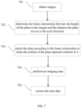
- the method may include obtaining CT images or topograms, determining the relationship between the heights of the plate from the floor in the CT images or topograms and the distances of the plate moving in the length direction of the plate, and adjusting the plate according to the relationship to make the movement of the adjusted plate fitting the relationship.
- the relationship may be linear or essentially linear.
- the method may include correcting the PET data after performing a PET scan.
- system means, “unit,” “module,” and/or “block” used herein are one method to distinguish different components, elements, parts, section or assembly of different level in ascending order. However, the terms may be displaced by other expression if they may achieve the same purpose.
- a relationship between the heights of the plate from a floor and the distances of the plate moving in an axial direction (or a length direction) of the plate is determined from images in advance.
- the plate may be adjusted so that the movement of the plate (including, for example, the movement along the axial direction, the height adjustment, and the bending of the plate) may conform to the relationship.
- an image of a patient may be obtained.
- Scan data may be corrected according to the position error between a height of the plate from the floor in previously acquired images and a height of the plate from the floor during imaging.
- the previously acquired images and the current images may be matched to facilitate image fusion.
- the imaging system or method according to the present disclosure may compensate a difference of the bending of the plate between different imaging modes. Consequently, the image matching or fusion may be simplified and the quality of image fusion may be improved.
- the system in the present disclosure may be CT, MRI, PET or any combination thereof.
- a PET/CT system combining CT with PET described below is merely provided for illustration purposes, and not intended to limit the scope of the present disclosure.
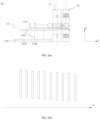
- FIG. 1(a) is a diagram of a prior art PET/CT system in which a CT scan is being performed
- FIG. 1(b) is a diagram illustrating the bending of the plate of a table in a CT scan
- FIG. 2(a) is a diagram of a prior art PET/CT system in which a PET scan is being performed
- FIG. 2(b) is a diagram illustrating the bending of the plate of a table in a PET scan.
- a PET/CT system may include a CT scanner 11, a PET scanner 12, and a table unit 13.
- the CT scanner 11 may be configured to run a CT scan and the PET scanner 12 may be configured to run a PET scan.
- the table unit 13 may include a base 133, a bracket 132 and a plate 131.
- the plate 131 may be configured to move relatively to the bracket 132 in an axial direction.
- There may be a position 1331 for CT scan (shown as dotted line) and a position 1332 for PET scan (shown as dotted line) on the base 133 along z axis which is parallel to a rotation axis of the CT scanner 11 (i.e., length direction of the plate 131).
- the bracket 132 at position 1331 may be used for CT scan, and the bracket 132 at position 1332 may be used for PET scan.
- the table 131 may be configured to support and transport the patient from a region to be imaged to a scanning cross-section of CT scanner 11 or a field of view (FOV) of PET scanner 12.
- the scanning cross-section is a plane perpendicular to the rotation axis and through an iso-center of the CT scanner 11.
- the distance between position 1331 and position 1332 along z axis may be equal to the distance between the iso-center of the CT scanner 11 and the center of FOV of the PET scanner 12.
- the bracket 132 may be placed at position 1331, and the plate 131 supporting the patient moves along the positive direction of the z axis t, and transfer the region to be imaged (e.g., head of the patient) to the scanning cross-section of the CT scanner 11.
- An x-ray tube of the CT scanner 11 may be configured to emit radiation rays and a detector of the CT scanner 11 may be configured to detect radiation rays traverses the region to be imaged.
- a reconstruction unit may be configured to reconstruct CT images based on a processed detected signal.
- the plate 131 may bend when moving towards the CT scanner 11 because of the weight of the patient and/or the weight of the plate itself. The further the plate 131 extends out, the more the plate 131 may bend.
- the height of the plate 131 at the scanning cross-section may be different.
- the height of the plate 131 may be the distance between the plate 131 and the floor on which the table (e.g., the base of the table) is placed.
- the bending of the plate 131 may increase along an inverse direction of the z axis, as shown in FIG. 1(b) . Please note that the bending of the plate 131 shown in FIG. 1(b) is exaggerated for illustration purposes.
- the bracket 132 at position 1332 and the plate 131 may operate in concert to transfer the region to be imaged of the patient to the FOV of the PET scanner 12.
- the plate 131 may bend due to the weight of the patient and/or the weight of the plate 131 itself.
- the plate 131 may be stationary. In the PET images so acquired, the bending of the plate 131 may increase along a positive direction of the z axis, as shown in FIG. 2(b) . Please note that the bending of the plate 131 shown in FIG. 2(b) is exaggerated for illustration purposes.
- the trends of the bending of the plate 131 in these two imaging modes are different. Because the distance between position 1331 and position 1332 is equal to the distance between the iso-center of the CT scanner 11 and the center of FOV of the PET scanner 12, the bending of the plate 131 at or around the portion corresponding to the middle of the region to be imaged in a CT image may be approximately equal to the bending of plate 131 in a corresponding PET image. The bending of other portions of the plate 131 in the CT image may be different from the bending of the plate in the corresponding PET image.
- an image showing both functional and anatomical information may be obtained by fusing a CT image and a PET image.
- an imaging system in some embodiments of the present disclosure may compensate a difference in the bending of the plate 131 between different imaging modes.
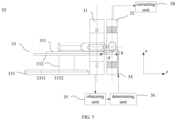
- FIG. 3 a diagram illustrating an exemplary PET/CT system according to some embodiments of the present disclosure.
- the PET/CT system 30 may include a CT scanner 31, a PET scanner 32, and a table unit 33.
- the CT scanner 31 and the PET scanner 32 may be coaxial.
- the CT scanner 31 and the PET scanner 32 may be non-coaxial.
- the table unit 33 may include a base 333, a bracket 332, and a plate 331.
- the plate 331 may be configured to move relatively to the bracket 332 along a length direction of the plate 331.
- a position 3331 for CT scan (indicated by a dotted line) and a position 3332 for PET scan (indicated by a dotted line) on the base 333 along the z axis.
- the z direction may be parallel to the rotation axis of the CT scanner 31 (also the length direction of the plate 331).
- a CT scan may be performed.
- a PET scan may be performed.
- the plate 331 may be configured to support and/or transport the patient so that the region to be imaged may be moved to the scanning cross-section of the CT scanner 31 or a field of view (FOV) of the PET scanner 32.
- FOV field of view
- the scanning cross-section is a plane through the iso-center and perpendicular to the rotation axis of the CT scanner 31.
- the PET/CT system 30 may further include an obtaining unit 35 and a determining unit 36.
- the obtaining unit 35 may be configured to obtain images.
- the obtaining unit 35 may be connected to the CT scanner 31.
- the obtaining unit 35 may acquire a CT image, instead of CT scan data.
- the CT scan data may be sent to a data acquisition unit and then reconstructed in an image reconstruction unit to generate the CT image provided to the obtaining unit 35.
- obtaining CT images is merely provided for illustration purposes, and not intended to limit the scope of the present disclosure.
- CT images may be computed tomographic images.
- the images obtained by the obtaining unit 35 may be topograms.
- a topogram may be a photograph acquired by setting the radiation source at a certain projection angle.
- CT images and topograms may be obtained through the CT unit 31 of the PET/CT system 30, or through one or more stand-alone CT apparatuses.
- the CT images or topograms may be images retrieved from a storage.
- the determining unit 36 may be configured to determine a relationship between the heights of the plate in the images (e.g., CT images, topograms, etc.) and the distances of the plate moving in the axial direction of the plate.
- a coordinate system may have its origin set at the iso-center of the CT scanner 31. Every pixel in a CT image may have a coordinate value.
- a minimal coordinate value in the x axis of the pixels corresponding to the plate 331 of CT images may be designated as a lowest point of the plate 331.
- the coordinate value in the x axis of the lowest point may represent a height of the plate 331.
- the height of the plate 331 may be the distance of the plate 331 from the floor on which the table unit 33 is placed.
- Coordinate values of the other pixels may be selected to represent the height of the plate 331.
- the height of the plate 331 of CT images may be obtained by other means.
- a measuring unit may measure the height of the plate 331 when the different portions of the plate 331 pass through the scanning cross-section.
- a distance measuring unit may measure the distance along the x axis between the portion of the plate 331 at the scanning cross-section and the distance measuring unit.
- the distance measuring unit may be a sonar or a laser rangefinder. Other devices that may measure the height of the plate 331 are within the scope of present disclosure.
- a displacement of the plate 331 along the z axis may be recorded.
- a relationship between the heights and the displacements of the plate 331 may be determined.
- the relationship between the heights and the displacements of the plate 331 may be approximately linear.
- the relationship between the heights and the displacements of the plate 331 may be determined by linear fitting.
- the displacements of the plate 331 may be the same as or relate to the distances of the plate moving in the axial direction. The shorter the scanning range is, the closer to being linear the relationship between the bending or the heights and the displacement of the plate 331 may be.
- the gradient of the linear relationship may be the ratio of a change in the bending to the corresponding change in the displacement of the plate 331 based on a geometric relationship.
- the ratio of the maximum change in the bending to the maximum relative displacement of the plate 331 may be calculated to obtain the gradient of the linear relationship.
- the maximum change in the bending of the plate 331 may refer to the maximum difference between the height of a first portion of the plate 331 in a first CT image and the height of a second portion of the plate 331 in a last CT image.
- the maximum relative displacement may refer to the difference between the position of the plate 331 in the z axis corresponding to the first CT image and the position of the plate 331 in the z axis corresponding to the last CT image.
- the gradient of the linear relationship may be symbolized by a parameter k .
- the linear relationship may be symbolized by one or more other parameters, for example, an angle with respect to the z axis.
- the plate 331 may be adjusted by the height adjustment unit 34 to conform to the linear relationship.
- the plate 331 may be supported by the bracket 332.
- the height adjustment unit 34 drives one end away from the bracket 332 of the plate 331 to move in a positive direction of the x axis, the plate 331 may not be separated from the bracket 332 completely.
- One unsupported end of the plate 131 may be raised by the height adjustment unit 34 to tilt the plate 331, such that a surface of the plate 331 may rise in a positive direction of the z axis.
- the height adjustment unit 34 may be installed underneath the plate 331.
- the height adjustment unit 34 may include a drive element configured to provide a driving force, a transform element configured to transform a rotation movement to a linear movement, and a transfer element connected to the transform element.
- the drive element may be, for example, a motor, etc.
- the transform element may include a lead screw and a nut. When the motor operates, the lead screw driven by the motor may rotate, and the nut may move in a straight line along the x axis. Meanwhile, the transfer element may move in a straight line together with the nut.
- the transfer element may drive one end of the plate 331 to rise together, as shown in FIG. 3 .
- the height adjustment unit 34 may adjust the height of the plate 331 to be level first, and then continue to raise one end of the plate 331.
- the distance between the bracket 332 and the height adjustment unit 34 in the z axis is symbolized by a parameter d .
- the distance of one end of the plate 331 away from the bracket 332 raised from the level is symbolized by a parameter h.
- the distance h may be monitored while the plate rises.
- a determination may be made as to whether the relationship among k , h , and d satisfies the following formula (1). If the formula (1) is satisfied, the plate 331 may have been adjusted in place. Otherwise, the plate 331 the plate 331 may continue to be adjusted as to the height of the plate 331.
- k h d .
- an encoder may monitor the rotation of the motor in order to monitor the distance h in real time.
- a distance measuring unit installed on the floor may monitor the distance h in real time by monitoring the distance between one end of the plate 331 and the distance measuring unit.
- Other devices for measuring the distance h are within the scope of the present disclosure and won't be enumerated here.
- the height adjustment unit 34 may include a device configured to drive one end of the plate 331 to rise and are not enumerated here.
- the height adjustment unit 34 may be installed on the floor, or on the gantry of the PET scanner 32.
- the height adjustment unit 34 may drive the plate 331 to move in the x axis and not affect imaging.
- the method and the location of installment of the height adjustment unit 34 are not limited to those exemplified in the present disclosure.
- the shape of the plate 331 may be kept and a PET scan may be performed.
- PET images may be obtained by reconstructing the PET scan data.
- the changing trend of the height of the plate 331 in the PET images may conform to the linear relationship.
- the relationship may be linear or essentially linear.
- the relationship may represent the changing trend of the height of the plate 331 in the CT images or topograms.
- the PET/CT system in the some embodiments may obtain CT images and PET images with the same or essentially the same changing trends of the height of the plate 331.
- the problem of different changing trends of the height of the plate 331 in different imaging modes may be solved.
- the fusion or matching of the images obtained in different imaging modes may be simplified.
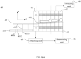
- FIG. 4 illustrates an exemplary PET/CT system according to some embodiments of the present disclosure.
- the PET/CT system is similar to the PET/CT system illustrated in FIG. 3 .
- the PET/CT system in FIG. 4 may include a computing unit 37 configured to compute a distance of the plate 331 that needs to be raised according to the relationship determined by the determining unit 36 described above.
- the gradient k may be obtained by the determining unit 36.
- the distance d between the bracket 332 and the height adjustment unit 34 in the z axis may be obtained as described elsewhere in the present disclosure.
- the distance h 0 of one end of the plate 331 away from the bracket 332 that needs to be raised from the horizontal level may be computed by the computing unit 37 according to the above formula (1).
- the height adjustment unit 34 may raise the end of the plate 331 by h 0 from the horizontal level. Similar with the description with reference to FIG.
- the height adjustment unit 34 may drive the plate 331 to a horizontal level, and then continue to drive the end of the plate 331 away from the bracket 332 to be raised by h 0 in the positive direction of the x axis so that the surface of the plate may fit the relationship described above.
- a PET scan may be performed. The problem of the different changing trends of the height of the plate in the CT imaging mode and the PET imaging mode may be solved. More descriptions may be found elsewhere in the present disclosure. See, for example, FIG. 3 and the description thereof.
- the position of the plate 331 in a CT image may be below the horizontal level, while the position of the plate 331 in a PET image may be above the horizontal level.
- the position error symbolized by a parameter ⁇ , may exist between the CT image and the PET image for a same slice.
- a changing trend of a position of the plate in the CT image mode and a changing trend of the same position of the plate in the PET imaging mode may be essentially the same.
- the position error ⁇ between each slice of a CT image and a corresponding portion of a PET image in the x axis may be approximately equal.
- a portion of a PET image may be referred to as corresponding to a slice of a CT image when the portion of the PET image and the slice of the CT image represent or depict a same portion of an object that is scanned.
- the position error ⁇ may be corrected to compensate the difference of the height of the plate between the CT imaging mode and the PET imaging mode and to match a CT image with a corresponding PET image.
- FIG. 5 is a diagram illustrating an exemplary PET/CT system according to some embodiments of the present disclosure.
- the PET/CT system may include a correcting unit 38 configured to correct the position error of the plate between the CT imaging mode and the PET imaging mode. Position errors in different systems may be different and may be obtained by experiments.
- CT images may be obtained by performing CT scans.
- the relationship between the heights of the plate and the distances of the plate moving in the axial direction may be determined based on CT images. Then the plate may be adjusted so that the heights of the plate conform to the relationship.
- PET images may be obtained by performing a PET scan at a height.
- Each position error of the plate between the CT image and the PET image in the x axis for each slice may be determined, and the mean value of all position errors may be used as the final position error ⁇ .
- the experiment may be repeated for multiple times using a water phantom and loads of different weights (e.g., wedges of different weights, etc.).
- loads of different weights e.g., wedges of different weights, etc.
- ⁇ 1 , ⁇ 2 , ..., ⁇ n may be obtained, in which n ⁇ 1 and n represents the times of the experiments.
- the times of the experiments for at least two loads of different weights may be the same or different.
- the mean value of ⁇ 1 , ⁇ 2 ... ⁇ n may be determined and used as the final position error ⁇ .
- the position errors ⁇ for loads of different weights may be obtained by experiments and may be stored for future use.
- the position errors ⁇ may be acquired directly based on the weight of a patient during a scan when needed.
- the correcting unit 38 may acquire the position error ⁇ corresponding to the patient and correct the data acquired in the PET scanning.
- the reconstruction unit of the PET scanner 32 may reconstruct the corrected data to obtain the PET images in which the positions of the plate of PET images may match the positions of the plate in the CT images. Because such experiments may be performed for a limited number of times, the number of position errors that may be obtained by experiments is limited.
- the weight of a patient may vary widely. When the weight of a patient is not already determined by experiment, the position error may be obtained by interpolation or extrapolation.
- the region to be examined is the head of a patient.
- the scanning range is short and the position error may be minor, for example, about a few millimeters.
- the correcting unit 38 may correct the position error as follows.
- the obtaining unit 35 may be configured to obtain images.
- the images may be CT images or topograms.
- the determining unit 36 may be configured to determine the relationship between the heights of the plate in the images and the distances of the plate moving in the axial direction.
- the height adjustment unit 34 may be configured to adjust the height of the plate based on the relationship, in order to make the movement of the adjusted plate fit the relationship.
- the correcting unit 38 may be configured to acquire the position error ⁇ based on the patient and send it to the controller of the table unit 33 and the height adjustment unit 34 such that the entire plate may be lowered by ⁇ in the x axis.
- the PET images in which the positions of the plate match the positions in CT images may be obtained by performing a PET scan.
- the distance ⁇ may be short, and thus the region to be examined may be still substantially within the center of FOV of the PET scanner 32.
- the PET/CT system may operate as follows.
- the obtaining unit 35 may be configured to obtain images.
- the images may be CT images or topograms.
- the determining unit 36 may be configured to determine the relationship between the heights of the plate in the images and the distances of the plate moving in the axial direction. The relationship may be linear or approximately linear.
- the correcting unit 38 may be configured to acquire the position error ⁇ corresponding to a patient and send the position error ⁇ to the controller of the table unit 33.
- the controller may make the plate 331 lower by ⁇ in the x axis.
- the region to be examined is the head of the patient.
- the scanning range is long, for example, in a whole body scan, at least a portion of the plate may bend greatly, and thus the need to compensate the height of the plate may be great.
Landscapes
- Health & Medical Sciences (AREA)
- Life Sciences & Earth Sciences (AREA)
- Engineering & Computer Science (AREA)
- Medical Informatics (AREA)
- Heart & Thoracic Surgery (AREA)
- Animal Behavior & Ethology (AREA)
- Biophysics (AREA)
- Nuclear Medicine, Radiotherapy & Molecular Imaging (AREA)
- Optics & Photonics (AREA)
- Pathology (AREA)
- Radiology & Medical Imaging (AREA)
- Biomedical Technology (AREA)
- Physics & Mathematics (AREA)
- Molecular Biology (AREA)
- Surgery (AREA)
- High Energy & Nuclear Physics (AREA)
- General Health & Medical Sciences (AREA)
- Public Health (AREA)
- Veterinary Medicine (AREA)
- Pulmonology (AREA)
- Theoretical Computer Science (AREA)
- Computer Vision & Pattern Recognition (AREA)
- Apparatus For Radiation Diagnosis (AREA)
- Magnetic Resonance Imaging Apparatus (AREA)
- Nuclear Medicine (AREA)
Applications Claiming Priority (2)
| Application Number | Priority Date | Filing Date | Title |
|---|---|---|---|
| US15/281,577 US10568596B2 (en) | 2016-06-30 | 2016-09-30 | Table system and method for PET/CT imaging |
| EP16207508.9A EP3300666B1 (de) | 2016-09-30 | 2016-12-30 | Tischsystem und verfahren zur pet-/ct-bildgebung |
Related Parent Applications (1)
| Application Number | Title | Priority Date | Filing Date |
|---|---|---|---|
| EP16207508.9A Division EP3300666B1 (de) | 2016-09-30 | 2016-12-30 | Tischsystem und verfahren zur pet-/ct-bildgebung |
Publications (2)
| Publication Number | Publication Date |
|---|---|
| EP4516232A2 true EP4516232A2 (de) | 2025-03-05 |
| EP4516232A3 EP4516232A3 (de) | 2025-05-07 |
Family
ID=57794088
Family Applications (2)
| Application Number | Title | Priority Date | Filing Date |
|---|---|---|---|
| EP25151857.7A Pending EP4516232A3 (de) | 2016-09-30 | 2016-12-30 | Tischsystem und verfahren zur pet/ct-bildgebung |
| EP16207508.9A Active EP3300666B1 (de) | 2016-09-30 | 2016-12-30 | Tischsystem und verfahren zur pet-/ct-bildgebung |
Family Applications After (1)
| Application Number | Title | Priority Date | Filing Date |
|---|---|---|---|
| EP16207508.9A Active EP3300666B1 (de) | 2016-09-30 | 2016-12-30 | Tischsystem und verfahren zur pet-/ct-bildgebung |
Country Status (1)
| Country | Link |
|---|---|
| EP (2) | EP4516232A3 (de) |
Families Citing this family (1)
| Publication number | Priority date | Publication date | Assignee | Title |
|---|---|---|---|---|
| CN112617877B (zh) * | 2021-01-05 | 2023-04-25 | 南京安科医疗科技有限公司 | 移动ct系统的自主扫描方法、存储介质和ct扫描装置 |
Family Cites Families (10)
| Publication number | Priority date | Publication date | Assignee | Title |
|---|---|---|---|---|
| CN2873102Y (zh) * | 2005-11-18 | 2007-02-28 | 沈阳东软派斯通医疗系统有限公司 | 多重成像系统 |
| CN100512759C (zh) * | 2006-04-13 | 2009-07-15 | Ge医疗系统环球技术有限公司 | 台装备识别方法和医疗成像装备 |
| US8175220B2 (en) * | 2008-08-05 | 2012-05-08 | General Electric Company | Method and apparatus for shortening footprint of multi-modality imaging system |
| US8063376B2 (en) * | 2008-08-15 | 2011-11-22 | Koninklijke Philips Electronics N.V. | Large bore PET and hybrid PET/CT scanners and radiation therapy planning using same |
| US8191190B2 (en) * | 2009-05-15 | 2012-06-05 | Koninklijke Philips Electronics N.V. | Deflection compensating mechanism for patient imaging table |
| JP5812756B2 (ja) * | 2011-08-19 | 2015-11-17 | 株式会社東芝 | 寝台装置及び機能画像/形態画像診断装置 |
| US20130298328A1 (en) * | 2012-05-11 | 2013-11-14 | General Electric Company | Positioning apparatus for positioning a patient in medical imaging system |
| JP6222795B2 (ja) * | 2012-06-20 | 2017-11-01 | 東芝メディカルシステムズ株式会社 | 画像診断装置及びその制御方法 |
| WO2014109338A1 (ja) * | 2013-01-08 | 2014-07-17 | 株式会社 東芝 | 医用画像診断装置、核医学診断装置、x線ct装置、及び寝台装置 |
| US20160113598A1 (en) * | 2013-05-01 | 2016-04-28 | Koninklijke Philips N.V. | Imaging system subject support tabletop deflection delta correction |
-
2016
- 2016-12-30 EP EP25151857.7A patent/EP4516232A3/de active Pending
- 2016-12-30 EP EP16207508.9A patent/EP3300666B1/de active Active
Also Published As
| Publication number | Publication date |
|---|---|
| EP4516232A3 (de) | 2025-05-07 |
| EP3300666B1 (de) | 2025-01-15 |
| EP3300666A1 (de) | 2018-04-04 |
Similar Documents
| Publication | Publication Date | Title |
|---|---|---|
| US10820868B2 (en) | Table system and method for PET/CT imaging | |
| CN107334485B (zh) | 使用外部图像捕获来限定ct扫描的扫描参数 | |
| US7269246B2 (en) | X-ray angiography apparatus | |
| US7607833B2 (en) | Method for operating a medical image apparatus to correct for deflection of the patient support board | |
| CN116777901B (zh) | 一种用于医学成像中的生成对象的三维模型的系统 | |
| US8107730B2 (en) | Imaging system sag correction method and apparatus | |
| JP7176689B2 (ja) | 生体磁気計測装置及び生体磁気計測方法 | |
| US8633945B2 (en) | X-ray diagnostic apparatus and image processing apparatus | |
| US20070053503A1 (en) | Methods and systems for automatic patient table positioning | |
| CN100387193C (zh) | 多重成像系统 | |
| CN106175810A (zh) | 一种成像装置及方法、pet/ct成像装置 | |
| US20170325754A1 (en) | Imaging system subject support | |
| EP3146900A1 (de) | Vorrichtung zum fotografieren medizinischer bilder und verfahren zur korrektur medizinischer bilder mit verwendung einer tiefenkamera | |
| CN114269236B (zh) | 具有运动检测系统的断层摄影成像系统 | |
| WO2026011886A1 (zh) | 医用放射检测装置、放射检测姿态ai识别及训练方法 | |
| EP3300666B1 (de) | Tischsystem und verfahren zur pet-/ct-bildgebung | |
| JP6045820B2 (ja) | コンピュータ断層撮影装置 | |
| US20180168528A1 (en) | X-ray diagnostic apparatus, medical image diagnostic system and control method | |
| US20190069862A1 (en) | Medical table and medical imaging apparatus including same | |
| JP2009000209A (ja) | 医用画像診断装置及びクレードル駆動装置の制御方法 | |
| US20240081754A1 (en) | Histotripsy water bath sensors to check registration and methods thereof | |
| CN106175816A (zh) | 一种病床装置、pet/ct成像装置及方法 | |
| JPWO2017022495A1 (ja) | 医用画像診断装置及びその制御方法 | |
| JP2005348841A (ja) | 画像診断装置 | |
| CN103889333A (zh) | 图像诊断装置及其控制方法 |
Legal Events
| Date | Code | Title | Description |
|---|---|---|---|
| PUAI | Public reference made under article 153(3) epc to a published international application that has entered the european phase |
Free format text: ORIGINAL CODE: 0009012 |
|
| STAA | Information on the status of an ep patent application or granted ep patent |
Free format text: STATUS: REQUEST FOR EXAMINATION WAS MADE |
|
| 17P | Request for examination filed |
Effective date: 20250114 |
|
| AC | Divisional application: reference to earlier application |
Ref document number: 3300666 Country of ref document: EP Kind code of ref document: P |
|
| AK | Designated contracting states |
Kind code of ref document: A2 Designated state(s): AL AT BE BG CH CY CZ DE DK EE ES FI FR GB GR HR HU IE IS IT LI LT LU LV MC MK MT NL NO PL PT RO RS SE SI SK SM TR |
|
| REG | Reference to a national code |
Ref country code: DE Ref legal event code: R079 Free format text: PREVIOUS MAIN CLASS: A61B0006000000 Ipc: A61B0006030000 |
|
| PUAL | Search report despatched |
Free format text: ORIGINAL CODE: 0009013 |
|
| AK | Designated contracting states |
Kind code of ref document: A3 Designated state(s): AL AT BE BG CH CY CZ DE DK EE ES FI FR GB GR HR HU IE IS IT LI LT LU LV MC MK MT NL NO PL PT RO RS SE SI SK SM TR |
|
| RIC1 | Information provided on ipc code assigned before grant |
Ipc: A61B 6/00 20240101ALI20250403BHEP Ipc: A61B 6/04 20060101ALI20250403BHEP Ipc: A61B 6/03 20060101AFI20250403BHEP |
|
| STAA | Information on the status of an ep patent application or granted ep patent |
Free format text: STATUS: EXAMINATION IS IN PROGRESS |
|
| 17Q | First examination report despatched |
Effective date: 20260105 |