EP4513643A1 - Batteriemodul und batteriepack - Google Patents
Batteriemodul und batteriepack Download PDFInfo
- Publication number
- EP4513643A1 EP4513643A1 EP23936787.3A EP23936787A EP4513643A1 EP 4513643 A1 EP4513643 A1 EP 4513643A1 EP 23936787 A EP23936787 A EP 23936787A EP 4513643 A1 EP4513643 A1 EP 4513643A1
- Authority
- EP
- European Patent Office
- Prior art keywords
- cell
- cooling plates
- liquid outlet
- current collectors
- liquid inlet
- Prior art date
- Legal status (The legal status is an assumption and is not a legal conclusion. Google has not performed a legal analysis and makes no representation as to the accuracy of the status listed.)
- Pending
Links
Images


Classifications
-
- H—ELECTRICITY
- H01—ELECTRIC ELEMENTS
- H01M—PROCESSES OR MEANS, e.g. BATTERIES, FOR THE DIRECT CONVERSION OF CHEMICAL ENERGY INTO ELECTRICAL ENERGY
- H01M10/00—Secondary cells; Manufacture thereof
- H01M10/60—Heating or cooling; Temperature control
- H01M10/61—Types of temperature control
- H01M10/613—Cooling or keeping cold
-
- H—ELECTRICITY
- H01—ELECTRIC ELEMENTS
- H01M—PROCESSES OR MEANS, e.g. BATTERIES, FOR THE DIRECT CONVERSION OF CHEMICAL ENERGY INTO ELECTRICAL ENERGY
- H01M10/00—Secondary cells; Manufacture thereof
- H01M10/60—Heating or cooling; Temperature control
- H01M10/62—Heating or cooling; Temperature control specially adapted for specific applications
- H01M10/625—Vehicles
-
- H—ELECTRICITY
- H01—ELECTRIC ELEMENTS
- H01M—PROCESSES OR MEANS, e.g. BATTERIES, FOR THE DIRECT CONVERSION OF CHEMICAL ENERGY INTO ELECTRICAL ENERGY
- H01M10/00—Secondary cells; Manufacture thereof
- H01M10/60—Heating or cooling; Temperature control
- H01M10/65—Means for temperature control structurally associated with the cells
- H01M10/653—Means for temperature control structurally associated with the cells characterised by electrically insulating or thermally conductive materials
-
- H—ELECTRICITY
- H01—ELECTRIC ELEMENTS
- H01M—PROCESSES OR MEANS, e.g. BATTERIES, FOR THE DIRECT CONVERSION OF CHEMICAL ENERGY INTO ELECTRICAL ENERGY
- H01M10/00—Secondary cells; Manufacture thereof
- H01M10/60—Heating or cooling; Temperature control
- H01M10/65—Means for temperature control structurally associated with the cells
- H01M10/655—Solid structures for heat exchange or heat conduction
- H01M10/6551—Surfaces specially adapted for heat dissipation or radiation, e.g. fins or coatings
-
- H—ELECTRICITY
- H01—ELECTRIC ELEMENTS
- H01M—PROCESSES OR MEANS, e.g. BATTERIES, FOR THE DIRECT CONVERSION OF CHEMICAL ENERGY INTO ELECTRICAL ENERGY
- H01M10/00—Secondary cells; Manufacture thereof
- H01M10/60—Heating or cooling; Temperature control
- H01M10/65—Means for temperature control structurally associated with the cells
- H01M10/655—Solid structures for heat exchange or heat conduction
- H01M10/6556—Solid parts with flow channel passages or pipes for heat exchange
- H01M10/6557—Solid parts with flow channel passages or pipes for heat exchange arranged between the cells
-
- H—ELECTRICITY
- H01—ELECTRIC ELEMENTS
- H01M—PROCESSES OR MEANS, e.g. BATTERIES, FOR THE DIRECT CONVERSION OF CHEMICAL ENERGY INTO ELECTRICAL ENERGY
- H01M10/00—Secondary cells; Manufacture thereof
- H01M10/60—Heating or cooling; Temperature control
- H01M10/65—Means for temperature control structurally associated with the cells
- H01M10/656—Means for temperature control structurally associated with the cells characterised by the type of heat-exchange fluid
- H01M10/6567—Liquids
- H01M10/6568—Liquids characterised by flow circuits, e.g. loops, located externally to the cells or cell casings
-
- H—ELECTRICITY
- H01—ELECTRIC ELEMENTS
- H01M—PROCESSES OR MEANS, e.g. BATTERIES, FOR THE DIRECT CONVERSION OF CHEMICAL ENERGY INTO ELECTRICAL ENERGY
- H01M10/00—Secondary cells; Manufacture thereof
- H01M10/60—Heating or cooling; Temperature control
- H01M10/65—Means for temperature control structurally associated with the cells
- H01M10/658—Means for temperature control structurally associated with the cells by thermal insulation or shielding
-
- H—ELECTRICITY
- H01—ELECTRIC ELEMENTS
- H01M—PROCESSES OR MEANS, e.g. BATTERIES, FOR THE DIRECT CONVERSION OF CHEMICAL ENERGY INTO ELECTRICAL ENERGY
- H01M50/00—Constructional details or processes of manufacture of the non-active parts of electrochemical cells other than fuel cells, e.g. hybrid cells
- H01M50/20—Mountings; Secondary casings or frames; Racks, modules or packs; Suspension devices; Shock absorbers; Transport or carrying devices; Holders
- H01M50/204—Racks, modules or packs for multiple batteries or multiple cells
- H01M50/207—Racks, modules or packs for multiple batteries or multiple cells characterised by their shape
- H01M50/209—Racks, modules or packs for multiple batteries or multiple cells characterised by their shape adapted for prismatic or rectangular cells
-
- H—ELECTRICITY
- H01—ELECTRIC ELEMENTS
- H01M—PROCESSES OR MEANS, e.g. BATTERIES, FOR THE DIRECT CONVERSION OF CHEMICAL ENERGY INTO ELECTRICAL ENERGY
- H01M50/00—Constructional details or processes of manufacture of the non-active parts of electrochemical cells other than fuel cells, e.g. hybrid cells
- H01M50/20—Mountings; Secondary casings or frames; Racks, modules or packs; Suspension devices; Shock absorbers; Transport or carrying devices; Holders
- H01M50/249—Mountings; Secondary casings or frames; Racks, modules or packs; Suspension devices; Shock absorbers; Transport or carrying devices; Holders specially adapted for aircraft or vehicles, e.g. cars or trains
-
- H—ELECTRICITY
- H01—ELECTRIC ELEMENTS
- H01M—PROCESSES OR MEANS, e.g. BATTERIES, FOR THE DIRECT CONVERSION OF CHEMICAL ENERGY INTO ELECTRICAL ENERGY
- H01M50/00—Constructional details or processes of manufacture of the non-active parts of electrochemical cells other than fuel cells, e.g. hybrid cells
- H01M50/20—Mountings; Secondary casings or frames; Racks, modules or packs; Suspension devices; Shock absorbers; Transport or carrying devices; Holders
- H01M50/258—Modular batteries; Casings provided with means for assembling
-
- H—ELECTRICITY
- H01—ELECTRIC ELEMENTS
- H01M—PROCESSES OR MEANS, e.g. BATTERIES, FOR THE DIRECT CONVERSION OF CHEMICAL ENERGY INTO ELECTRICAL ENERGY
- H01M50/00—Constructional details or processes of manufacture of the non-active parts of electrochemical cells other than fuel cells, e.g. hybrid cells
- H01M50/20—Mountings; Secondary casings or frames; Racks, modules or packs; Suspension devices; Shock absorbers; Transport or carrying devices; Holders
- H01M50/289—Mountings; Secondary casings or frames; Racks, modules or packs; Suspension devices; Shock absorbers; Transport or carrying devices; Holders characterised by spacing elements or positioning means within frames, racks or packs
-
- H—ELECTRICITY
- H01—ELECTRIC ELEMENTS
- H01M—PROCESSES OR MEANS, e.g. BATTERIES, FOR THE DIRECT CONVERSION OF CHEMICAL ENERGY INTO ELECTRICAL ENERGY
- H01M50/00—Constructional details or processes of manufacture of the non-active parts of electrochemical cells other than fuel cells, e.g. hybrid cells
- H01M50/30—Arrangements for facilitating escape of gases
- H01M50/317—Re-sealable arrangements
-
- H—ELECTRICITY
- H01—ELECTRIC ELEMENTS
- H01M—PROCESSES OR MEANS, e.g. BATTERIES, FOR THE DIRECT CONVERSION OF CHEMICAL ENERGY INTO ELECTRICAL ENERGY
- H01M50/00—Constructional details or processes of manufacture of the non-active parts of electrochemical cells other than fuel cells, e.g. hybrid cells
- H01M50/30—Arrangements for facilitating escape of gases
- H01M50/342—Non-re-sealable arrangements
- H01M50/3425—Non-re-sealable arrangements in the form of rupturable membranes or weakened parts, e.g. pierced with the aid of a sharp member
-
- H—ELECTRICITY
- H01—ELECTRIC ELEMENTS
- H01M—PROCESSES OR MEANS, e.g. BATTERIES, FOR THE DIRECT CONVERSION OF CHEMICAL ENERGY INTO ELECTRICAL ENERGY
- H01M50/00—Constructional details or processes of manufacture of the non-active parts of electrochemical cells other than fuel cells, e.g. hybrid cells
- H01M50/50—Current conducting connections for cells or batteries
- H01M50/502—Interconnectors for connecting terminals of adjacent batteries; Interconnectors for connecting cells outside a battery casing
- H01M50/507—Interconnectors for connecting terminals of adjacent batteries; Interconnectors for connecting cells outside a battery casing comprising an arrangement of two or more busbars within a container structure, e.g. busbar modules
-
- H—ELECTRICITY
- H01—ELECTRIC ELEMENTS
- H01M—PROCESSES OR MEANS, e.g. BATTERIES, FOR THE DIRECT CONVERSION OF CHEMICAL ENERGY INTO ELECTRICAL ENERGY
- H01M10/00—Secondary cells; Manufacture thereof
- H01M10/60—Heating or cooling; Temperature control
- H01M10/64—Heating or cooling; Temperature control characterised by the shape of the cells
- H01M10/647—Prismatic or flat cells, e.g. pouch cells
-
- H—ELECTRICITY
- H01—ELECTRIC ELEMENTS
- H01M—PROCESSES OR MEANS, e.g. BATTERIES, FOR THE DIRECT CONVERSION OF CHEMICAL ENERGY INTO ELECTRICAL ENERGY
- H01M2220/00—Batteries for particular applications
- H01M2220/20—Batteries in motive systems, e.g. vehicle, ship, plane
-
- Y—GENERAL TAGGING OF NEW TECHNOLOGICAL DEVELOPMENTS; GENERAL TAGGING OF CROSS-SECTIONAL TECHNOLOGIES SPANNING OVER SEVERAL SECTIONS OF THE IPC; TECHNICAL SUBJECTS COVERED BY FORMER USPC CROSS-REFERENCE ART COLLECTIONS [XRACs] AND DIGESTS
- Y02—TECHNOLOGIES OR APPLICATIONS FOR MITIGATION OR ADAPTATION AGAINST CLIMATE CHANGE
- Y02E—REDUCTION OF GREENHOUSE GAS [GHG] EMISSIONS, RELATED TO ENERGY GENERATION, TRANSMISSION OR DISTRIBUTION
- Y02E60/00—Enabling technologies; Technologies with a potential or indirect contribution to GHG emissions mitigation
- Y02E60/10—Energy storage using batteries
Definitions
- the present disclosure relates to the technical field of batteries, in particular to a battery module and a battery pack.
- power batteries are the energy center of electric vehicles. As power battery technology becomes more and more widely used, the market puts forward higher requirements for the cruising range and safety of power batteries.
- CTP cell to pack
- the embodiments of the present disclosure provide a battery module and a battery pack for solving or at least partially solving the shortcomings of the above background.
- the embodiments of the present disclosure provide a battery module, including:
- the embodiments of the present disclosure provide a battery pack, including:
- the embodiment of the present disclosure provides a battery module and a battery pack.
- the battery module includes a cell assembly and a tray.
- the cell assembly includes a plurality of cell groups arranged at intervals along a first direction.
- Each of the cell groups includes a plurality of cells arranged at intervals along a second direction.
- the tray includes a plurality of cell accommodating grooves arranged at intervals along the first direction.
- One of the cell accommodating grooves is arranged corresponding to one of the cell sub groups.
- a coolant flow channel is arranged in a side wall of each of the cell accommodating grooves.
- connection and “coupled” are used broadly, and may be, for example, fixed connections or detachable connections; may also be mechanical connections or electrical connections; may also be direct connections or indirect connections via intervening structures; may also be inner communications of two elements or interaction relationships between two elements.
- connection and “coupled” are used broadly, and may be, for example, fixed connections or detachable connections; may also be mechanical connections or electrical connections; may also be direct connections or indirect connections via intervening structures; may also be inner communications of two elements or interaction relationships between two elements.
- a structure in which a first feature is “on” or “below” a second feature may include an embodiment in which the first feature is in direct contact with the second feature, and may also include an embodiment in which the first feature and the second feature are not in direct contact with each other, but are contacted via an additional feature formed therebetween.
- a first feature "on”, “above”, or “on top of” a second feature may include an embodiment in which the first feature is right or obliquely “on”, “above”, or “on top of” the second feature, or just means that the first feature is at a height higher than that of the second feature.
- a first feature "below”, “under”, or “on bottom of” a second feature may include an embodiment in which the first feature is right or obliquely “below”, “under”, or “on bottom of” the second feature, or just means that the first feature is at a height lower than that of the second feature.
- the embodiments of the present disclosure provide a battery module and a battery pack. Hereinafter, each of them will be described in detail. It should be noted that the order of description of the following embodiments is not intended to limit the preferred order of the embodiments.
- the battery module 1 includes a cell assembly 10 and a tray 21.
- the cell assembly 10 includes a plurality of cell sub groups 11.
- the plurality of cell sub groups 11 are arranged at intervals along a first direction X.
- the cell sub group 11 includes a plurality of cells 111. In any one of the cell sub groups 11, the plurality of cells 111 are arranged at intervals along a second direction Y.
- the tray 21 includes a plurality of cell accommodating grooves 21A arranged at intervals along the first direction X.
- One cell accommodating groove is arranged corresponding to one cell sub group 11.
- a coolant flow channel 221 is arranged in a side wall of the cell accommodating groove 21A.
- CTP cell to pack
- the coolant flow channel 221 in the side wall of the cell accommodating groove 21A by providing the coolant flow channel 221 in the side wall of the cell accommodating groove 21A, the coolant flow channel 221 and the tray 21 are integrated into a whole without providing an additional liquid cooling plate.
- the structure is more simplified, the space utilization of the battery module 1 can be effectively improved, and the manufacturing cost of the battery module 1 can be reduced.
- FIG. 1 is a schematic structural view of the battery module provided by the embodiments of the present disclosure
- FIG. 2 is an explosion view of the battery module provided by the embodiments of the present disclosure.
- the embodiments provide a battery module 1 including a cell assembly 10 and a tray 21.
- the cell assembly 10 includes a plurality of cell sub groups 11.
- the plurality of cell sub groups 11 are arranged at intervals along a first direction X.
- the cell sub group 11 includes a plurality of cells 111. In any one of the cell sub groups 11, the plurality of cells 111 are arranged at intervals along a second direction Y.
- the tray 21 includes a plurality of cell accommodating grooves 21A arranged at intervals along the first direction X.
- One cell accommodating groove is arranged corresponding to one cell sub group 11.
- a coolant flow channel 221 is arranged in a side wall of the cell accommodating groove 21A.
- the battery module 1 further includes a plurality of current collectors 24 disposed at both ends of the side wall of the cell accommodating groove 21A.
- a plurality of connecting members 23 are disposed between adjacent current collectors 24.
- the current collectors 24 on one side are provided with a liquid inlet hole 24A, and the current collectors 24 on another side are provided with a liquid outlet hole 24B.
- the coolant flow channel 221 is filled with coolant, and the coolant circulates in and out of the coolant flow channel 221 through the liquid inlet hole 24A and the liquid outlet hole 24B.
- the connecting member 23 includes, but is not limited to, a bellows 231.
- the first direction is marked by X
- the second direction is marked by Y
- the first direction X and the second direction Y form a preset included angle.
- the present disclosure is illustrated by taking the preset included angle as a right angle as an example.
- FIG. 3 is a schematic cross-sectional view at position A-A' in FIG. 1 .
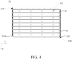
- FIG. 4 is a top view of a liquid cooling assembly provided by the embodiments of the present disclosure.
- FIG. 5 is a schematic cross-sectional view of a cooling plate provided by the embodiments of the present disclosure.
- the tray 21 includes a baseplate 211 and a plurality of cooling plates 22 located on the baseplate 211.
- the plurality of cooling plates 22 are arranged at intervals along the first direction X.
- One cell accommodating groove 21A is located between adjacent cooling plates 22.
- the tray 21 and the cooling plates 22 may be integrally formed.
- the cooling plates 22 and the current collectors 24 may be fixed by welding, thereby simplifying the structure of the tray 21 and reducing costs.
- the cooling plate 22 includes a plurality of coolant flow channels 221.
- the plurality of coolant flow channels 221 are arranged at intervals along the third direction Z.
- the coolant flow channels 221 penetrate the cooling plate 22 along the second direction Y. Both ends of the coolant flow channel 221 are provided with a liquid inlet port 221A and a liquid outlet port 221B, respectively.
- the liquid inlet port 221A is in communication with the liquid inlet hole 24A.
- Aliquid outlet port 221B is in communication with the liquid outlet hole 24B.
- the third direction is marked by Z.
- the third direction Z is provided perpendicular to the first direction X.
- the third direction Z is provided perpendicular to the second direction Y.
- the battery module 1 includes a plurality of first current collectors 241 and a plurality of second current collectors 242.
- the first current collectors 241 are provided with the liquid inlet hole 24A.
- the second current collectors 242 are provided with the liquid outlet hole 24B.
- Both ends of the coolant flow channel 221 are provided with a liquid inlet 221A and a liquid outlet 221B, respectively.
- the liquid inlet port 221A is in communication with the first current collectors 241.
- the liquid outlet port 221B is in communication with the second current collectors 242.
- the coolant flow channel 221 is preferably a linear channel. The coolant circulates in and out of the cooling plate 22 through the liquid inlet hole 24A, the liquid inlet port 221A, the coolant flow channel 221, the liquid outlet port 221B, and the liquid outlet hole 24B.
- the coolant flow channel 221 is provided in the side wall of the cell accommodating tank 21A, that is, in the cooling plate 22, the coolant flow channel 221 and the tray 21 are integrated into a whole.
- the cooling plate 22 is filled with coolant, and the coolant circulates in and out of the cooling plate 22 through the liquid inlet hole 24A, the liquid inlet port 221A, the coolant flow channel 221, the liquid outlet port 221B, and the liquid outlet hole 24B, so that liquid cooling heat dissipation of the cell 111 can be achieved.
- the cell 111 includes a first side surface 111A and a second side surface 111B.
- the first side surface 111A is disposed close to a side wall of the cell accommodating groove 21A.
- the second side surface 111B is located between adjacent cells 111.
- a length of the first side surface 111A is greater than a length of the second side surface 111B.
- the battery module 1 further includes a plurality of heat insulating layers 12 and a plurality of thermally conductive structural adhesives 13.
- the heat insulating layer 12 is located between the second side surfaces 111B of the adjacent cells 111.
- the thermally conductive structural adhesive 13 is located between the side wall of the cell accommodating groove 21A and the cell 111.
- the heat insulating layer 12 is preferably one or more of a fiber layer, a heat insulating foam, a heat insulating cotton, and a heat conductive adhesive.
- the cell 111 is a square shell cell.
- the cooling plate 22 has a flat structure to be adapted to the first side surface 111A of the square shell cell. It can be understood that in some embodiments, by providing the heat insulating layer 12 to be filled between the adjacent cells 111, the cooling efficiency of the cells 111 is improved. Further, by providing the thermally conductive structural adhesive 13 to be filled between the cell 111 and the cooling plate 22, the cell 111 and the cooling plate 22 are closely attached to each other, thereby improving the tightness and stiffness of the liquid cooling assembly 20, thereby preventing the cell 111 from expanding to affect the service life of the battery module 1. In some embodiments, a structural adhesive (not shown in the figure) may also be used to fixedly connect the cell 111 with the tray 21. The connection is convenient and reliable, and the cell 111 is effectively prevented from loosening and falling off.
- the cell 111 includes a thermal runaway nozzle.
- the thermal runaway nozzle is provided correspondingly to the explosion-proof valve 111C.
- the explosion-proof valve 111C is installed on the thermal runaway nozzle. It can be understood that when thermal runaway occurs in one of the cells 111 on the tray 21, the chemicals and gases of the cell 111 are directionally ejected from the thermal runaway nozzle.
- the thermal runaway nozzle of the cell 111 is aligned with the pressure relief hole 210, so that both the chemicals and gases of the cell 111 are directionally ejected into the pressure relief hole 210, thereby releasing pressure from the pressure relief hole 210 to the outside of the battery module 1.
- FIG. 6 is a schematic structural view of a battery pack provided by some embodiments of the present disclosure.
- FIG. 7 is a cross-sectional top view of the battery pack provided by some embodiments of the present disclosure.
- the present embodiments provide a battery pack 2 including a box 2A and a plurality of cell modules 2B.
- the box 2A includes a bottom plate 2A1 and a plurality of side beams 2A2.
- the plurality of side beams 2A2 are fixedly arranged on the edges of the bottom plate 2A1 to enclose to form a accommodation cavity 2C.
- the plurality of cell modules 2B are located in the accommodation cavity 2C.
- the plurality of cell modules 2B are arranged at intervals along the first direction X.
- the plurality of cell module 2B includes a plurality of cell modules 1 arranged at intervals along the second direction Y.
- the battery modules 1 include the battery module 1 described in any one of the above embodiments.
- the plurality of side beams 2A2 are sequentially connected to enclose to form a plurality of annular structures 2D.
- the annular structures 2D and the battery modules 1 are in one-to-one correspondence.
- the annular structures 2D are disposed around the battery modules 1.
- the bottom plate 2A1 and the plurality of side beams 2A2 form a plurality of accommodating sub cavities 2C1 for placing the battery modules 1.
- One of the accommodating sub cavities 2C1 is provided corresponding to one of the battery modules 1.
- the technical solution of the present disclosure is illustrated by taking the battery pack 2 including a first battery module 1A, a second battery module 1B, a third battery module 1C, and a fourth battery module 1D as an example.
- the plurality of cooling plates 22 include two first cooling plates 22A and a plurality of second cooling plates 22B.
- the two first cooling plates 22A are disposed opposite each other along the first direction X.
- the plurality of second cooling plates 22B are disposed between the two first cooling plates 22A at intervals.
- the first cooling plate 22A includes an extension portion 22A1 extending from an end of the first cooling plate 22A towards a direction away from the second cooling plate 22B, and the extension portion 22A1 is fixedly connected to the side beam 2A2.
- the extension portion 22A1 includes a plurality of first openings 22A11 provided at intervals along the second direction Y.
- the side beam 2A2 includes a plurality of second openings provided at intervals along the second direction Y.
- the first openings 22A11 and the second openings are in one-to-one correspondence.
- the extension portion 22A1 and the side beam 2A2 are connected by threads.
- the first cooling plate 22A includes an extension portion 22A1, the extension portion 22A1 extends from the end of the first cooling plate 22A towards the direction away from the second cooling plate 22B, and the extension portion 22A1 is fixedly connected to the side beam 2A2, so that the battery module 1 is limited, the battery module 1 can be prevented from moving when the battery pack 2 is subjected to external impact, and the stability of the battery pack 2 can be improved.
- the extension portion 22A1 and the side beam 2A2 by providing a threaded connection between the extension portion 22A1 and the side beam 2A2, the disassembly, assembly and maintenance are facilitated.
- the box 2A further includes a liquid outlet pipeline 2A4 located between adjacent cell modules 2B, and two liquid inlet pipelines 2A3 opposite each other along the first direction X.
- the liquid inlet pipeline 2A3 is located on a side of the battery module 1 away from the liquid outlet pipeline 2A4.
- the liquid outlet pipeline 2A4 is provided with a plurality of liquid outlet openings 2A41 sequentially arranged along the second direction Y.
- the liquid inlet pipeline 2A3 is provided with a plurality of liquid inlet openings 2A31 sequentially arranged along the second direction Y.
- one of the liquid inlet openings 2A31 is provided corresponding to one of the first cooling plates 22A, and the liquid inlet opening 2A31 is in communication with the liquid inlet hole 24A of the current collector 24 corresponding to the one of the first cooling plates 22A.
- One of the liquid outlet openings 2A41 is provided corresponding to the other of the first cooling plates 22A, and the liquid outlet opening 2A41 is in communication with the liquid outlet hole 24B of the current collector 24 corresponding to the other of first cooling plate 22A.
- the liquid inlet pipeline 2A3 includes a liquid inlet nozzle 2A32
- the liquid outlet pipeline 2A4 includes a liquid outlet nozzle 2A42.
- the liquid inlet nozzle 2A32 is connected to an external device (not shown in the figure), and the liquid outlet nozzle 2A42 is connected to an external device.
- the external device is a conventional device, and is capable of supplying a coolant to the liquid cooling module 20 and recovering the coolant flowing out of the liquid cooling module 20.
- the coolant enters the cooling plate 22 from the liquid inlet nozzle 2A32.
- the coolant circulates in and out of the cooling plate 22 through the liquid inlet hole 24A and the liquid outlet hole 24B.
- the coolant flows back from the liquid outlet nozzle 2A42 to the external device.
- the flow direction of the coolant is: a1 ⁇ b1 ⁇ c1 ⁇ d1 ⁇ e1.
- the flow direction of the coolant is: a1 ⁇ b2 ⁇ c2 ⁇ d2 ⁇ e2.
- the flow direction of the coolant is: a2 ⁇ b3 ⁇ c3 ⁇ d3 ⁇ e2.
- the flow direction of the coolant is: a2 ⁇ b4 ⁇ c4 ⁇ d4 ⁇ e2.
- the box 2A further includes a liquid outlet pipeline 2A4 located between the adjacent cell modules 2B and two liquid inlet pipelines 2A3 opposite each other along the first direction X, so that the structure is simplified, the installation space is reduced, the disassembly, assembly and maintenance are facilitated, and the cost is also reduced. Further, the coolant flows in from both sides of the box 2A and then flows out between the adjacent cell modules 2B, thereby reducing the flow resistance of the coolant inlet in the liquid cooling assembly 20 and improving the heat dissipation effect of the cooling plate 22.
- the coolant flows from the liquid inlet pipeline 2A3 on both sides into the cooling plate 22 of each module and then collects in the liquid outlet pipeline 2A4 in the middle portion.
- the space is saved, and the temperature uniformity of heat dissipation can be improved by the way of collecting from both sides to the middle portion.
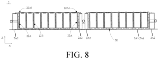
- FIG. 8 is a schematic cross-sectional view of a battery pack provided by the embodiments of the present disclosure.
- the tray 21, the bottom plate 2A1, and the side beam 2A2 are surrounded to form a pressure relief channel 2E.
- the pressure relief hole 210 is in communication with the pressure relief channel 2E.
- the hole diameter of the pressure relief hole 210 is smaller than the diameter of the cell 111.
- the design of the pressure relief channel 2E reduces the impact generated when the cell 111 bursts, and improves the safety of the operation of the battery module 1.
- providing the pressure relief hole 210 can quickly dissipate the heat of the cell 111 or the gas generated when thermal runaway occurs in the battery from the bottom of the cell 111.
- the heat dissipation effect is enhanced, the safety performance of the structure of the battery pack 2 is increased, the gas pressure inside the battery pack 2 is reduced, and the gas generated by the cell 111 is prevented from entering the accommodation cavity 2C, thereby ensuring that the temperature of the accommodation cavity 2C does not rise rapidly.
- a material of the box 2A is a metal.
- the tray 21 is made of plastic or other material with good insulation, which can prevent the bottom surface of the cell 111 from coming into contact with the bottom plate 2A1 and play an insulation protection role.
- a mica plate may also be provided between the tray 21 and the bottom plate 2A1, and the mica plate covers the pressure relief hole 210. The chemicals and gases sprayed by the cells 111 are sprayed onto the mica plate first, thereby preventing the box 2A from being burned through.
- the present embodiments provide an electrical device including the battery module in any one of the above embodiments.
- the electrical device includes the battery module, and the battery module is used as a power supply for the electrical device. Therefore, the electrical device also has various advantages of the battery module, thereby helping to simplify the overall structure of the electrical device.
- the electrical device may be an automobile, an aircraft, a mechanical production apparatus, or the like.
Landscapes
- Chemical & Material Sciences (AREA)
- Chemical Kinetics & Catalysis (AREA)
- Electrochemistry (AREA)
- General Chemical & Material Sciences (AREA)
- Engineering & Computer Science (AREA)
- Manufacturing & Machinery (AREA)
- Aviation & Aerospace Engineering (AREA)
- Secondary Cells (AREA)
- Battery Mounting, Suspending (AREA)
- Gas Exhaust Devices For Batteries (AREA)
- Connection Of Batteries Or Terminals (AREA)
Applications Claiming Priority (2)
| Application Number | Priority Date | Filing Date | Title |
|---|---|---|---|
| CN202321591191.4U CN220021368U (zh) | 2023-06-20 | 2023-06-20 | 电池模组和电池包 |
| PCT/CN2023/132534 WO2024259885A1 (zh) | 2023-06-20 | 2023-11-20 | 电池模组和电池包 |
Publications (2)
| Publication Number | Publication Date |
|---|---|
| EP4513643A1 true EP4513643A1 (de) | 2025-02-26 |
| EP4513643A4 EP4513643A4 (de) | 2026-02-11 |
Family
ID=88681672
Family Applications (1)
| Application Number | Title | Priority Date | Filing Date |
|---|---|---|---|
| EP23936787.3A Pending EP4513643A4 (de) | 2023-06-20 | 2023-11-20 | Batteriemodul und batteriepack |
Country Status (6)
| Country | Link |
|---|---|
| US (1) | US20250140982A1 (de) |
| EP (1) | EP4513643A4 (de) |
| JP (1) | JP2025525283A (de) |
| KR (1) | KR20240178257A (de) |
| CN (1) | CN220021368U (de) |
| WO (1) | WO2024259885A1 (de) |
Families Citing this family (3)
| Publication number | Priority date | Publication date | Assignee | Title |
|---|---|---|---|---|
| CN220021368U (zh) * | 2023-06-20 | 2023-11-14 | 惠州亿纬锂能股份有限公司 | 电池模组和电池包 |
| KR20250141972A (ko) * | 2024-03-21 | 2025-09-30 | 주식회사 엘지에너지솔루션 | 압출형 팩 하우징 및 그 제조방법 |
| EP4647704A1 (de) * | 2024-05-10 | 2025-11-12 | Eve Energy Co., Ltd. | Kühlkomponente und batteriepack |
Family Cites Families (14)
| Publication number | Priority date | Publication date | Assignee | Title |
|---|---|---|---|---|
| DE102014200983B4 (de) * | 2014-01-21 | 2023-12-14 | Robert Bosch Gmbh | Batteriesystem mit mehreren Batteriezellen und einem Gehäuse, Gehäusesystem für eine Batterie und Verfahren zur Montage eines Batteriesystems |
| KR102803108B1 (ko) * | 2018-12-21 | 2025-05-07 | 아와 세이시 가부시키가이샤 | 전원 장치 및 전원 장치용 단열 시트 |
| CN215299355U (zh) * | 2021-07-30 | 2021-12-24 | 蜂巢能源科技有限公司 | 电池包和用于电池包的冷却系统 |
| EP4187698A1 (de) * | 2021-11-26 | 2023-05-31 | Volvo Car Corporation | Kühlsystem für ein- und mehraufnahme-ev-strukturbatterien |
| CN116724453A (zh) * | 2021-11-30 | 2023-09-08 | 宁德时代新能源科技股份有限公司 | 电池模块、电池包、用电装置和制造电池模块的方法 |
| WO2024031413A1 (zh) * | 2022-08-10 | 2024-02-15 | 宁德时代新能源科技股份有限公司 | 电池以及用电装置 |
| EP4468452A4 (de) * | 2022-06-27 | 2025-01-08 | Contemporary Amperex Technology Co., Limited | Wärmeverwaltungsvorrichtung, batterie und elektrische vorrichtung |
| CN218123570U (zh) * | 2022-09-23 | 2022-12-23 | 楚能新能源股份有限公司 | 一种电池模组 |
| CN218568986U (zh) * | 2022-10-24 | 2023-03-03 | 湖北亿纬动力有限公司 | 模组托盘以及电池模组 |
| CN218731481U (zh) * | 2022-10-27 | 2023-03-24 | 赛格威科技有限公司 | 电池模组外壳、电池模组和全地形车 |
| CN115441121B (zh) * | 2022-11-08 | 2023-02-07 | 楚能新能源股份有限公司 | 一种延缓热失控的电池模组、电池包及电动车 |
| CN218632348U (zh) * | 2022-11-22 | 2023-03-14 | 浙江极氪智能科技有限公司 | 电池包及汽车 |
| CN115966808A (zh) * | 2023-01-13 | 2023-04-14 | 惠州亿纬锂能股份有限公司 | 一种集成式侧面液冷电池包及电动汽车 |
| CN220021368U (zh) * | 2023-06-20 | 2023-11-14 | 惠州亿纬锂能股份有限公司 | 电池模组和电池包 |
-
2023
- 2023-06-20 CN CN202321591191.4U patent/CN220021368U/zh active Active
- 2023-11-20 WO PCT/CN2023/132534 patent/WO2024259885A1/zh active Pending
- 2023-11-20 EP EP23936787.3A patent/EP4513643A4/de active Pending
- 2023-11-20 JP JP2024564952A patent/JP2025525283A/ja active Pending
- 2023-11-20 KR KR1020247035775A patent/KR20240178257A/ko active Pending
-
2024
- 2024-12-29 US US19/004,406 patent/US20250140982A1/en active Pending
Also Published As
| Publication number | Publication date |
|---|---|
| US20250140982A1 (en) | 2025-05-01 |
| CN220021368U (zh) | 2023-11-14 |
| KR20240178257A (ko) | 2024-12-30 |
| EP4513643A4 (de) | 2026-02-11 |
| JP2025525283A (ja) | 2025-08-05 |
| WO2024259885A1 (zh) | 2024-12-26 |
Similar Documents
| Publication | Publication Date | Title |
|---|---|---|
| EP4513643A1 (de) | Batteriemodul und batteriepack | |
| CN219203266U (zh) | 电池以及用电装置 | |
| US20250038300A1 (en) | Battery cooling system, battery pack, and vehicle | |
| US20250023199A1 (en) | Battery, electrical apparatus and battery forming method | |
| WO2023004720A1 (zh) | 电池、用电装置以及电池的制造方法和制造系统 | |
| US20250079605A1 (en) | Thermal management component, battery, and electric apparatus | |
| US20250112296A1 (en) | Thermal management component, thermal management system, battery, and electric apparatus | |
| US20250087831A1 (en) | Battery and electric apparatus | |
| WO2024037655A1 (zh) | 电池模组上盖结构、电池模组及电池包 | |
| CN116169415A (zh) | 电池箱体及电池包 | |
| CN118315747A (zh) | 一种圆柱电池包及其组装方法 | |
| US20250279504A1 (en) | Heat exchange assembly, battery and electrical device | |
| US20250246710A1 (en) | Heat exchanging assembly, battery module, battery, electrical device | |
| WO2024124689A1 (zh) | 电池及用电装置 | |
| US20250293342A1 (en) | Battery and electric device | |
| US20250372799A1 (en) | Pressure relief assembly, battery module, battery pack, and powered device | |
| CN222939996U (zh) | 一种冷却单元以及电池包 | |
| WO2024250694A1 (zh) | 电池及用电设备 | |
| CN114421086B (zh) | 一种汽车动力锂离子电池模组结构 | |
| CN223296959U (zh) | 一种电池包以及用电设备 | |
| CN222338392U (zh) | 新能源汽车的电池包总成及新能源汽车 | |
| CN116799428B (zh) | 具有防止热扩散功能的液冷电池模组 | |
| CN218602557U (zh) | 电池包 | |
| US20250309466A1 (en) | Pressure relief structure for double-layer battery and battery pack | |
| CN220774513U (zh) | 换热组件、电池及用电设备 |
Legal Events
| Date | Code | Title | Description |
|---|---|---|---|
| STAA | Information on the status of an ep patent application or granted ep patent |
Free format text: STATUS: UNKNOWN |
|
| STAA | Information on the status of an ep patent application or granted ep patent |
Free format text: STATUS: THE INTERNATIONAL PUBLICATION HAS BEEN MADE |
|
| PUAI | Public reference made under article 153(3) epc to a published international application that has entered the european phase |
Free format text: ORIGINAL CODE: 0009012 |
|
| STAA | Information on the status of an ep patent application or granted ep patent |
Free format text: STATUS: REQUEST FOR EXAMINATION WAS MADE |
|
| 17P | Request for examination filed |
Effective date: 20241119 |
|
| AK | Designated contracting states |
Kind code of ref document: A1 Designated state(s): AL AT BE BG CH CY CZ DE DK EE ES FI FR GB GR HR HU IE IS IT LI LT LU LV MC ME MK MT NL NO PL PT RO RS SE SI SK SM TR |
|
| A4 | Supplementary search report drawn up and despatched |
Effective date: 20260114 |
|
| RIC1 | Information provided on ipc code assigned before grant |
Ipc: H01M 50/209 20210101AFI20260108BHEP Ipc: H01M 50/244 20210101ALI20260108BHEP Ipc: H01M 50/249 20210101ALI20260108BHEP Ipc: H01M 50/258 20210101ALI20260108BHEP Ipc: H01M 10/613 20140101ALI20260108BHEP Ipc: H01M 10/625 20140101ALI20260108BHEP Ipc: H01M 10/6567 20140101ALI20260108BHEP Ipc: H01M 50/289 20210101ALI20260108BHEP Ipc: H01M 10/653 20140101ALI20260108BHEP Ipc: H01M 10/6557 20140101ALI20260108BHEP Ipc: H01M 10/658 20140101ALI20260108BHEP |