EP4513636A1 - Batteriezelle, batteriemodul und batteriepack - Google Patents
Batteriezelle, batteriemodul und batteriepack Download PDFInfo
- Publication number
- EP4513636A1 EP4513636A1 EP23216288.3A EP23216288A EP4513636A1 EP 4513636 A1 EP4513636 A1 EP 4513636A1 EP 23216288 A EP23216288 A EP 23216288A EP 4513636 A1 EP4513636 A1 EP 4513636A1
- Authority
- EP
- European Patent Office
- Prior art keywords
- reinforcing member
- cell
- cover plate
- outer casing
- cells
- Prior art date
- Legal status (The legal status is an assumption and is not a legal conclusion. Google has not performed a legal analysis and makes no representation as to the accuracy of the status listed.)
- Granted
Links
Images


Classifications
-
- H—ELECTRICITY
- H01—ELECTRIC ELEMENTS
- H01M—PROCESSES OR MEANS, e.g. BATTERIES, FOR THE DIRECT CONVERSION OF CHEMICAL ENERGY INTO ELECTRICAL ENERGY
- H01M50/00—Constructional details or processes of manufacture of the non-active parts of electrochemical cells other than fuel cells, e.g. hybrid cells
- H01M50/20—Mountings; Secondary casings or frames; Racks, modules or packs; Suspension devices; Shock absorbers; Transport or carrying devices; Holders
- H01M50/233—Mountings; Secondary casings or frames; Racks, modules or packs; Suspension devices; Shock absorbers; Transport or carrying devices; Holders characterised by physical properties of casings or racks, e.g. dimensions
- H01M50/242—Mountings; Secondary casings or frames; Racks, modules or packs; Suspension devices; Shock absorbers; Transport or carrying devices; Holders characterised by physical properties of casings or racks, e.g. dimensions adapted for protecting batteries against vibrations, collision impact or swelling
-
- H—ELECTRICITY
- H01—ELECTRIC ELEMENTS
- H01M—PROCESSES OR MEANS, e.g. BATTERIES, FOR THE DIRECT CONVERSION OF CHEMICAL ENERGY INTO ELECTRICAL ENERGY
- H01M50/00—Constructional details or processes of manufacture of the non-active parts of electrochemical cells other than fuel cells, e.g. hybrid cells
- H01M50/10—Primary casings; Jackets or wrappings
- H01M50/147—Lids or covers
- H01M50/166—Lids or covers characterised by the methods of assembling casings with lids
- H01M50/169—Lids or covers characterised by the methods of assembling casings with lids by welding, brazing or soldering
-
- H—ELECTRICITY
- H01—ELECTRIC ELEMENTS
- H01M—PROCESSES OR MEANS, e.g. BATTERIES, FOR THE DIRECT CONVERSION OF CHEMICAL ENERGY INTO ELECTRICAL ENERGY
- H01M10/00—Secondary cells; Manufacture thereof
- H01M10/04—Construction or manufacture in general
- H01M10/0481—Compression means other than compression means for stacks of electrodes and separators
-
- H—ELECTRICITY
- H01—ELECTRIC ELEMENTS
- H01M—PROCESSES OR MEANS, e.g. BATTERIES, FOR THE DIRECT CONVERSION OF CHEMICAL ENERGY INTO ELECTRICAL ENERGY
- H01M50/00—Constructional details or processes of manufacture of the non-active parts of electrochemical cells other than fuel cells, e.g. hybrid cells
- H01M50/10—Primary casings; Jackets or wrappings
- H01M50/102—Primary casings; Jackets or wrappings characterised by their shape or physical structure
- H01M50/103—Primary casings; Jackets or wrappings characterised by their shape or physical structure prismatic or rectangular
-
- H—ELECTRICITY
- H01—ELECTRIC ELEMENTS
- H01M—PROCESSES OR MEANS, e.g. BATTERIES, FOR THE DIRECT CONVERSION OF CHEMICAL ENERGY INTO ELECTRICAL ENERGY
- H01M50/00—Constructional details or processes of manufacture of the non-active parts of electrochemical cells other than fuel cells, e.g. hybrid cells
- H01M50/10—Primary casings; Jackets or wrappings
- H01M50/14—Primary casings; Jackets or wrappings for protecting against damage caused by external factors
-
- H—ELECTRICITY
- H01—ELECTRIC ELEMENTS
- H01M—PROCESSES OR MEANS, e.g. BATTERIES, FOR THE DIRECT CONVERSION OF CHEMICAL ENERGY INTO ELECTRICAL ENERGY
- H01M50/00—Constructional details or processes of manufacture of the non-active parts of electrochemical cells other than fuel cells, e.g. hybrid cells
- H01M50/10—Primary casings; Jackets or wrappings
- H01M50/147—Lids or covers
- H01M50/148—Lids or covers characterised by their shape
- H01M50/15—Lids or covers characterised by their shape for prismatic or rectangular cells
-
- H—ELECTRICITY
- H01—ELECTRIC ELEMENTS
- H01M—PROCESSES OR MEANS, e.g. BATTERIES, FOR THE DIRECT CONVERSION OF CHEMICAL ENERGY INTO ELECTRICAL ENERGY
- H01M50/00—Constructional details or processes of manufacture of the non-active parts of electrochemical cells other than fuel cells, e.g. hybrid cells
- H01M50/20—Mountings; Secondary casings or frames; Racks, modules or packs; Suspension devices; Shock absorbers; Transport or carrying devices; Holders
- H01M50/204—Racks, modules or packs for multiple batteries or multiple cells
- H01M50/207—Racks, modules or packs for multiple batteries or multiple cells characterised by their shape
- H01M50/209—Racks, modules or packs for multiple batteries or multiple cells characterised by their shape adapted for prismatic or rectangular cells
-
- H—ELECTRICITY
- H01—ELECTRIC ELEMENTS
- H01M—PROCESSES OR MEANS, e.g. BATTERIES, FOR THE DIRECT CONVERSION OF CHEMICAL ENERGY INTO ELECTRICAL ENERGY
- H01M50/00—Constructional details or processes of manufacture of the non-active parts of electrochemical cells other than fuel cells, e.g. hybrid cells
- H01M50/50—Current conducting connections for cells or batteries
- H01M50/572—Means for preventing undesired use or discharge
- H01M50/584—Means for preventing undesired use or discharge for preventing incorrect connections inside or outside the batteries
- H01M50/588—Means for preventing undesired use or discharge for preventing incorrect connections inside or outside the batteries outside the batteries, e.g. incorrect connections of terminals or busbars
-
- H—ELECTRICITY
- H01—ELECTRIC ELEMENTS
- H01M—PROCESSES OR MEANS, e.g. BATTERIES, FOR THE DIRECT CONVERSION OF CHEMICAL ENERGY INTO ELECTRICAL ENERGY
- H01M50/00—Constructional details or processes of manufacture of the non-active parts of electrochemical cells other than fuel cells, e.g. hybrid cells
- H01M50/50—Current conducting connections for cells or batteries
- H01M50/572—Means for preventing undesired use or discharge
- H01M50/584—Means for preventing undesired use or discharge for preventing incorrect connections inside or outside the batteries
- H01M50/59—Means for preventing undesired use or discharge for preventing incorrect connections inside or outside the batteries characterised by the protection means
- H01M50/595—Tapes
-
- B—PERFORMING OPERATIONS; TRANSPORTING
- B23—MACHINE TOOLS; METAL-WORKING NOT OTHERWISE PROVIDED FOR
- B23K—SOLDERING OR UNSOLDERING; WELDING; CLADDING OR PLATING BY SOLDERING OR WELDING; CUTTING BY APPLYING HEAT LOCALLY, e.g. FLAME CUTTING; WORKING BY LASER BEAM
- B23K2101/00—Articles made by soldering, welding or cutting
- B23K2101/36—Electric or electronic devices
-
- B—PERFORMING OPERATIONS; TRANSPORTING
- B23—MACHINE TOOLS; METAL-WORKING NOT OTHERWISE PROVIDED FOR
- B23K—SOLDERING OR UNSOLDERING; WELDING; CLADDING OR PLATING BY SOLDERING OR WELDING; CUTTING BY APPLYING HEAT LOCALLY, e.g. FLAME CUTTING; WORKING BY LASER BEAM
- B23K26/00—Working by laser beam, e.g. welding, cutting or boring
- B23K26/20—Bonding
- B23K26/21—Bonding by welding
- B23K26/24—Seam welding
- B23K26/244—Overlap seam welding
-
- Y—GENERAL TAGGING OF NEW TECHNOLOGICAL DEVELOPMENTS; GENERAL TAGGING OF CROSS-SECTIONAL TECHNOLOGIES SPANNING OVER SEVERAL SECTIONS OF THE IPC; TECHNICAL SUBJECTS COVERED BY FORMER USPC CROSS-REFERENCE ART COLLECTIONS [XRACs] AND DIGESTS
- Y02—TECHNOLOGIES OR APPLICATIONS FOR MITIGATION OR ADAPTATION AGAINST CLIMATE CHANGE
- Y02E—REDUCTION OF GREENHOUSE GAS [GHG] EMISSIONS, RELATED TO ENERGY GENERATION, TRANSMISSION OR DISTRIBUTION
- Y02E60/00—Enabling technologies; Technologies with a potential or indirect contribution to GHG emissions mitigation
- Y02E60/10—Energy storage using batteries
Definitions
- the disclosure belongs to the technical field of batteries, and in particular, relates to a cell, a battery module and a battery pack.
- the assembly of the top cover and the aluminum casing relies on the embedding of the side steps of the aluminum casing and the surrounding steps below the top cover piece, and laser welding is then performed to complete the assembly of the casing and the cover.
- the square casing cell uses the aluminum casing as a current collector container. When the cell is charged and discharged, gas will be produced and the electrode sheets will expand, causing the aluminum casing to be pushed outward and expand. The gas produced by the cell, the expansion of the electrode sheets, and resulting outward expansion of the aluminum casing cause the welded seam of the casing cover at the corresponding position to be torn. Long-term exposure to the fatigue expansion force may cause the strength of the welded seam of the casing cover to be weakened, or the welded seam may even be torn and fails, so the safety of the cell is thus affected.
- the disclosure aims to provide a cell and a battery module, so as to address the problems of cell safety being affected, strength of a casing cover welded seam being weakened, and the casing cover welded seam being torn and failing caused by long-term exposure to a fatigue expansion force as the casing cover welded seam at the corresponding position is torn by the outward expansion of an aluminum casing resulted from generation of gas and expansion of electrode sheets when the cell is charged and discharged.
- the disclosure provides a cell including an outer casing, a cover plate, and a reinforcing member.
- the cover plate is welded to a top portion of the outer casing.
- the reinforcing member at least includes a first surface and a second surface.
- the first surface is fixedly connected to one of the cover plate and the outer casing, and the second surface faces the other one of the cover plate and the outer casing.
- the cell further includes an electrode assembly stacked in the outer casing in a thickness direction, a length direction, or a height direction of the cell.
- the first surface is fixedly connected to the cover plate, and the second surface faces a large surface of the outer casing.
- the first surface is fixedly connected to the cover plate, and the second surface faces a narrow surface of the outer casing.
- the first surface is fixedly connected to the outer casing, and the second surface faces the cover plate.
- the reinforcing member is a L-shaped reinforcing member, a C-shaped reinforcing member, a T-shaped reinforcing member, or an annular reinforcing member.
- a ratio of a length of the reinforcing member to a length of the cover plate is less than or equal to 1
- the reinforcing membe includes a plurality of segmented reinforcing members, and the plurality of segmented reinforcing members are arranged at intervals, when the reinforcing member is the L-shaped reinforcing member, a width of the L-shaped reinforcing member on the cover plate close to an explosion-proof valve is less than or equal to (a-b)/2, where a is a width of the cover plate and b is a width of the explosion-proof valve, and when the reinforcing member is the C-shaped reinforcing member, the C-shaped reinforcing member further includes a third surface, and the third surface and the second surface face two opposite large surfaces of the outer casing respectively.
- An escape groove is provided on the first surface, and the escape groove faces an explosion-proof valve on the cover plate.
- the cell further includes a top patch, a groove is provided on a side of the top patch close to the reinforcing member to form an escape zone, and a portion of the reinforcing member arranged on the cover plate is located in the escape zone.
- an insulating layer including a heat shrinkable sleeve film, an insulating tape, or a blue film is further provided.
- the heat shrinkable sleeve film surrounds a top portion top of the cell and covers a surface of the reinforcing member.
- the insulating tape or the blue film is attached to the surface of the reinforcing member.
- the disclosure further provides a battery module including a casing body, a cell stack, and reinforcing members.
- the cell stack includes a plurality of cells, and each of the cells includes an outer casing and a cover plate welded to a top portion of the outer casing.
- the reinforcing members are at least arranged on outer sides of the two outermost cells of the cell stack, and each of the reinforcing members at least includes a first surface and a second surface.
- the first surface is fixedly connected to one of the cover plate and the outer casing, and the second surface faces the other one of the cover plate and the outer casing.
- each of the cells are provided with one of the reinforcing members.
- the cell stack includes a plurality of single cell groups.
- the reinforcing members are provided on the two cells located on two sides of each of the single cell groups.
- the disclosure provides a cell, a battery module and a battery pack.
- the disclosure provides a cell, a battery module and a battery pack.
- the cell stack includes an even number of the cells and the positive and negative electrodes of the cells are arranged in an alternating manner, the L-shaped reinforcing members are provided only on the outer sides of the two outermost cells of the cell stack. In this way, the welded seam is ensured not to fail during the cyclic swelling process of the cells. Further, when the number of the cells is an even number, the two outermost cells are completely identical, so only one production line is needed to produce the cells with the reinforcing members, and production costs may be effectively reduced.
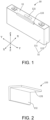
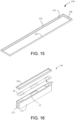
- a cell 10 includes an outer casing 11, a cover plate 12, and a reinforcing member 13, and a top portion of the outer casing 11 is provided with an opening.
- the cover plate 12 is installed on the top portion of outer casing 11, and specifically, is installed at the opening on the top portion of the outer casing 11 and is welded and fixed to the outer casing 11.
- the reinforcing member 13 is arranged between the cover plate 12 and the outer casing 11 and is configured to improve strength of a welded seam between the cover plate 12 and the outer casing 11.
- the reinforcing member 13 at least includes a first surface 131 and a second surface 132.
- the first surface 131 is fixedly connected to one of the cover plate 12 and the outer casing 11, and the second surface 132 faces the other one of the cover plate 12 and the outer casing 11.
- the second surface 132 faces the cover plate 12 or the outer casing 11 from the front.
- the first surface 131 is fixedly connected to the cover plate 12, and the second surface 132 faces a surface of the outer casing 11 from the front.
- the first surface 131 is fixedly connected to the outer casing 11, and the second surface 132 faces the cover plate 12 from the front.
- first surface 131 and the cover plate 12 or the outer casing 11 may be connected by laser welding or gluing.
- the second surface 132 and the outer casing 11 or the cover plate 12 may be connected by laser welding or gluing or may be arranged directly opposite each other and are not fixedly connected to each other. In this way, when the cell 10 swells, the swelling of the cell 10 is limited, so that the relative displacement of the outer casing 11 and the cover plate 12 in the cell 10 is limited, so it is ensured that the welded seam does not fail during the cycle, and a casing cover welded seam is effectively protected.
- a ratio of an aspect ratio of the cell 10 is greater than 12, and the cell under this aspect ratio is more likely to swell, thereby causing the casing cover welded seam to fail. Therefore, the reinforcing member 13 is provided on the cell 10, so as to limit the swelling of the cell 10 when the cell 10 swells.
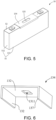
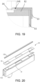
- the reinforcing member 13 may be any one of a L-shaped reinforcing member 133, a C-shaped reinforcing member 134, a T-shaped reinforcing member 135, and an annular reinforcing member 136.
- the reinforcing member 13 may be connected to the cover plate 12 and the outer casing 11 through laser welding or glue 1301, so an additional device is not required, and it is easy and efficient to operate.
- the first surface 131 being fixedly connected to the cover plate 12 and the second surface 132 facing the large surface 111 of the outer casing 11 is taken as an example for description.
- the L-shaped reinforcing member 133 includes one first surface 131 and one second surface 132.
- the first surface 131 and the second surface are located on one side of the first surface 131 and are bent opposite to the first surface 131.
- the first surface 131 is welded and fixed to the cover plate 12 through laser welding, and the second surface 132 faces the large surface 111 of the outer casing 11.
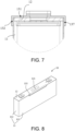
- the T-shaped reinforcing member 135 includes a wing plate 1351, a sub-plate 1352, two first surfaces 131, and two second surfaces 132.
- the two second surfaces 132 are arranged respectively on two sides of the sub-plate 1352, and the two second surfaces 132 are respectively arranged on a bottom portion of the wing plate 1351 on the two sides of the sub-plate 1352.
- the sub-plate 1352 and the wing plate 1352 are arranged perpendicularly to each other.
- the T-shaped reinforcing member 135 may be disposed between two cells 10.
- the two first surfaces 131 are welded and fixed to the cover plates 12 of the two cells 10 through laser welding respectively, and the two second surfaces 132 face the large surfaces 111 of the outer casings 11 of the two cells 10 respectively, so that one T-shaped reinforcing member 135 may limit the outward expansion of the large surfaces 111 of the outer casings 11 of the two cells 10 together.
- the first surface 131 and the second surface 132 may be fixedly connected to the cover plate 12 and the large surface 111 of the outer casing 11 respectively through the glue 1301.
- a ratio of a length of each of the L-shaped reinforcing member 133, the C-shaped reinforcing member 134, and the T-shaped reinforcing member 135 to a length of the cover plate 12 is set to be less than or equal to 1. That is, the lengths of the L-shaped reinforcing member 133, the C-shaped reinforcing member 134, and the T-shaped reinforcing member T 135 are less than the length of the cover plate 12. Further, a width of a contact zone between the reinforcing member 13 and the outer casing 11 is set to be between 1 mm and 10 mm to ensure that the reinforcing member 13 limits the swelling of the cell 10.
- a width of the L-shaped reinforcing member 133 on the cover plate 12 close to an explosion-proof valve 121 is less than or equal to (a-b)/2, where a is a width of the cover plate 12 and b is a width of the explosion-proof valve 121, so that the L-shaped reinforcing member 133 is prevented from interfering with the explosion-proof valve 121.
- a ratio of a height of the second surface 132 of the reinforcing member 13 to a height of the outer casing 11 of the cell is greater than 3%, and a width of the first surface 131 of the reinforcing member 13 is greater than one-tenth of the width of the cover plate. In this way, it is ensured that the reinforcing member 13 may be reliably fixed onto the cell 10 and the reliability of limiting the swelling of the cell 10 may be ensured.
- one large surface 111 of the outer casing 11 may be provided with the L-shaped reinforcing member 133 or the T-shaped reinforcing member 13, or two large surfaces 111 of the outer casing 11 may both be provided with the L-shaped reinforcing members 133 or T-shaped reinforcing members 135.
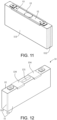
- the C-shaped reinforcing member 134 further includes a third surface 137.
- the second surface 132 and the third surface 137 are respectively located on two sides of the first surface 131 and are bent relative to the first surface 131.
- the second surface 132 and the third surface 137 are both perpendicular to the first surface 137, and the third surface 137 and the second surface 132 face the two opposite large surfaces 111 of the outer casing 1 respectively.
- an escape groove 1311 is provided on the first surface 13, and the escape groove 1311 faces the explosion-proof valve 121 on the cover plate 12 to avoid the explosion-proof valve 121.
- the C-shaped reinforcing member 134 may also be configured as a segmented structure. That is, the C-shaped reinforcing member 134 includes a plurality of segmented reinforcing members, and the plurality of segmented reinforcing members are arranged at intervals to avoid the explosion-proof valve 121. Further, the segmented reinforcing members may be arranged to target a key zone of the welded seam between the cover plate 12 and the outer casing 11, so that the casing cover welded seam may be effectively protected.
- each of the L-shaped reinforcing member 133 and the T-shaped reinforcing member 135 may be configured as a segmented structure as well. That is, each of the L-shaped reinforcing member 133 and the T-shaped reinforcing member 135 includes a plurality of segmented reinforcing members respectively.
- the segmented reinforcing members may be arranged at intervals to target the key zone of the welded seam between the cover plate 12 and the outer casing 11, so that the casing cover welded seam may be effectively protected.
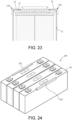
- the annular reinforcing member 136 surrounds the welded part of the outer casing 11 and the cover plate 12 to wrap the welded seam between the outer casing 11 and the cover plate 12, so that the relative displacement of the outer casing 11 and the cover plate 12 is limited, and the welded seam is ensured not to fail during the cycle, and that the casing cover welded seam is effectively protected.
- the annular reinforcing member 136 includes the first surface 131, the second surface 132, the third surface 137, and two opposite fourth surfaces 138.
- the second surface 132 and the third surface 137 are respectively located on two sides of the first surface 131
- the fourth surfaces 138 are located on the other two sides of the first surface 131
- the second surface 132, the third surface 137, and the fourth surfaces 138 are bent relative to the first surface 131.
- the second surface 132, the third surface 137, and the fourth surfaces 138 are respectively perpendicularly to the first surface 131, and the first surface 131 is fixedly connected to the cover plate 12.
- the third surface 137 and the second surface 132 face the two opposite large surfaces 111 of the outer casing 11 respectively.
- the two opposite fourth surfaces 138 face the two opposite narrow surfaces 112 of the outer casing 11 respectively, so that the relative displacement of the outer casing 11 and the cover plate 12 is limited, and the casing cover welded seam is effectively protected.
- the reinforcing member 13 occupies an envelope space of a side surface and a top surface of an original cell, that is, the reinforcing member 13 occupies the space on the side and top surfaces of the original cell.
- the raised part forms a plurality of outer surfaces, making insulation application more difficult and making conventional top patches, blue film structures, and gluing methods no longer applicable.
- the main body or part of the reinforcing member is exposed, an external insulating exposure point is formed, so the risk of external short circuit increases significantly, and the insulation performance of the cell is affected.
- the side surface of the reinforcing member 13 greatly increase the difficulty of insulating film application.
- an escape zone 141 is provided on a top patch 14, and to be specific, a groove is provided on a side of the top patch 14 close to the reinforcing member 13 to form the escape zone 141.
- the groove is formed by partially cutting a side of the top patch 14 close to the reinforcing member 13.
- a shape of the groove matches a shape of a portion of the reinforcing member 13 arranged on the cover plate 12, and an insulating layer is added to the reinforcing member 13 to ensure its insulation performance.
- the escape zone 141 may also be formed by performing corresponding heat pressing on a local zone of the top patch 14 close to one side of the reinforcing member 13 to form a protrusion.
- the portion of the reinforcing member 13 provided on the cover plate 12 is located in the escape zone 141.
- the reinforcing member 13 is a L-shaped reinforcing member 133
- the portion of the L-shaped reinforcing member 133 provided on the cover plate 12 is located in the escape zone 141.
- an insulating layer is provided on a surface of the reinforcing member 13 to solve the problem of aluminum exposure on one side edge of the top cover caused by the welding of the reinforcing member 13, so that a good external insulation effect is provided, and the external insulation performance of the cell is ensured.
- the insulating layer may be provided as a heat shrinkable sleeve film 151.
- the heat shrinkable sleeve film 151 surrounds a top portion top of the cell 10 and covers the surface of the reinforcing member 13. By heating and shrinking, the heat shrinkable sleeve film 151 is attached around the top portion of the cell 10 to cover the top patch 1, and insulation protection is thereby achieved.
- the insulating layer may also be configured as an insulating material such as an insulating tape 152 or a blue film and is attached to the surface of the reinforcing member 13.
- an insulating material such as an insulating tape 152 or a blue film and is attached to the surface of the reinforcing member 13.
- Two ends of the insulating tape 152 or the blue film protrude from two ends of the reinforcing member 13, and portions protruding from the reinforcing member 13 are folded and cover side surfaces of the reinforcing member 13.
- the side surfaces of the reinforcing member 13 are special-shaped surfaces when the insulating film is applied. It is difficult to form the insulating film at one time, and it is easy to form exposed points, so the risk of insulation increases.
- the surface of the reinforcing member 13 has insulating capability by addition of a heating shrinkable insulating sleeve, integral immersing, or insulating material spraying. As described above, after the reinforcing member 13 is welded, the insulating layer is attached to its exposed surface, so that its external insulation effect is further improved.
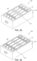
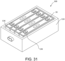
- a battery module 100 includes a casing body 110, a cell stack 120, and reinforcing members 13.
- the cell stack 120 is installed in the casing body 110 and includes a plurality of cells 10 stacked together.
- the swelling of outer surfaces of the two outermost cells 10 in the cell stack 120 is most obvious.
- the relative displacement between an outer casing 11 and a cover plate 12 located outside the two outermost cells 10 is relatively large, so that a welded seam at this location is most susceptible to failure during the cyclic swelling process. Therefore, in this embodiment, the reinforcing members 13 at least are provided on the outer sides of the two outermost cells 10 of the cell stack 120.
- each of the cells 10 may be provided with one of the reinforcing members 13.
- each reinforcing member 13 may be any one of a L-shaped reinforcing member 133, a C-shaped reinforcing member 134, a T-shaped reinforcing member 135, and an annular reinforcing member 136.
- the cell stack 120 includes a plurality of single cell groups.
- Each of the single cell groups includes at least one of the cells 10, and the single cell groups are connected in series or in parallel.
- the number of the single cell groups is preferably an even number, and the plurality of single cell groups are preferably connected in series. That is, the cell stack includes an even number of cells 10 connected in series, and positive and negative electrodes of the even number of cells 10 connected in series are arranged in an alternating manner.
- each of the reinforcing members 13 is preferably a L-shaped reinforcing member 133 or a T-shaped reinforcing member 135.
- the two outermost cells 10 in the cell stack 120 are completely identical and may share a single production line for production.
- the reinforcing members 13 require the least consumable materials, so the reinforcing members 13 can effectively protect a casing cover welded seam and protect the swelled cells, and its production costs are also preferably reduced.
- the reinforcing members 13 may be provided on the two cells 10 located on two sides of each of the single cell groups.
- the plurality of cells 10 in each single cell group are connected in series or in parallel.
- the reinforcing members 13 are provided on the sides of the two cells 10 away from each other in the single cell group, and the reinforcing members 13 are preferably the L-shaped reinforcing members 133.
- one T-shaped reinforcing member 135 is arranged on sides close to each other of the two adjacent single cell groups. That is, the T-shaped reinforcing member 135 is located between two adjacent cells 10 in the two adjacent single cell groups, so that one T-shaped reinforcing member 135 can limit the outward swelling of two cells 10 at the same time.
- the reinforcing members 13 are preferably the C-shaped reinforcing members 134 or the annular reinforcing members 136.
- the two outermost cells 10 in the cell stack 120 are completely identical and may share a single production line for production.
- the reinforcing members 13 therefore can effectively protect the casing cover welded seam and protect the swelled cells, and its production costs are also preferably reduced.
- the positive and negative electrodes of the plurality of cells 10 are preferably arranged in an alternating manner.
- the positive and negative electrodes of the plurality of cells 10 are preferably arranged on the same side.
- the disclosure further provides a battery pack including the cell as described above or the battery module as described above.
- the disclosure provides a cell, a battery module and a battery pack.
- the reinforcing member By arranging the reinforcing member on the cell, the problem of cyclic cracking caused by insufficient strength of the welded seam is solved. Further, the relative displacement between the casing body and the top cover of the cell is limited, so it is ensured that the welded seam does not fail during the cycle, the casing cover welded seam is effectively protected, and the swelled cell is protected. Further, the reinforcing member is connected to the cover plate and the casing body through laser welding or gluing, so an additional device is not required, and the operation is easy and efficient.
- the disclosure provides a cell, a battery module and a battery pack.
- the disclosure provides a cell, a battery module and a battery pack.
- the disclosure provides a cell, a battery module and a battery pack.
- the cell stack includes an even number of the cells and the positive and negative electrodes of the cells are arranged in an alternating manner, the L-shaped reinforcing members are provided only on the outer sides of the two outermost cells of the cell stack. In this way, the welded seam is ensured not to fail during the cyclic swelling process of the cells. Further, when the number of the cells is an even number, the two outermost cells are completely identical, so only one production line is needed to produce the cells with the reinforcing members, and production costs may be effectively reduced.
- the "plurality” described in the above embodiments includes two and more than two.
- the "faces” in which a specific surface of the reinforcing member faces the cover plate or the outer casing means that a specific surface of the reinforcing member falls on the cover plate along a projection perpendicular to the cover plate, or a specific surface of the reinforcing member falls on the large surface or the narrow surface along the projection perpendicular to the large surface or the narrow surface of the outer casing.
- the second surface faces the large surface of the outer casing means that the second surface of the reinforcing member falls on the large surface along a projection perpendicular to the large surface.
Landscapes
- Chemical & Material Sciences (AREA)
- Chemical Kinetics & Catalysis (AREA)
- Electrochemistry (AREA)
- General Chemical & Material Sciences (AREA)
- Engineering & Computer Science (AREA)
- Manufacturing & Machinery (AREA)
- Sealing Battery Cases Or Jackets (AREA)
- Battery Mounting, Suspending (AREA)
Applications Claiming Priority (1)
| Application Number | Priority Date | Filing Date | Title |
|---|---|---|---|
| CN202322275807.3U CN220731650U (zh) | 2023-08-23 | 2023-08-23 | 一种电芯及电池模组 |
Publications (2)
| Publication Number | Publication Date |
|---|---|
| EP4513636A1 true EP4513636A1 (de) | 2025-02-26 |
| EP4513636B1 EP4513636B1 (de) | 2025-10-15 |
Family
ID=89222411
Family Applications (1)
| Application Number | Title | Priority Date | Filing Date |
|---|---|---|---|
| EP23216288.3A Active EP4513636B1 (de) | 2023-08-23 | 2023-12-13 | Batteriezelle, batteriemodul und batteriepack |
Country Status (5)
| Country | Link |
|---|---|
| US (1) | US20250070340A1 (de) |
| EP (1) | EP4513636B1 (de) |
| JP (1) | JP7766071B2 (de) |
| CN (1) | CN220731650U (de) |
| ES (1) | ES3050084T3 (de) |
Families Citing this family (1)
| Publication number | Priority date | Publication date | Assignee | Title |
|---|---|---|---|---|
| EP4668421A3 (de) * | 2024-05-24 | 2026-01-21 | Samsung Sdi Co., Ltd. | Sekundärbatterie und batteriemodul damit |
Citations (4)
| Publication number | Priority date | Publication date | Assignee | Title |
|---|---|---|---|---|
| JP4951814B2 (ja) * | 2001-03-21 | 2012-06-13 | 新神戸電機株式会社 | 扁平型二次電池及び電池モジュール |
| JP2014170678A (ja) * | 2013-03-04 | 2014-09-18 | Mitsubishi Motors Corp | 二次電池 |
| US20220123421A1 (en) * | 2018-12-28 | 2022-04-21 | GS Yuasa lnternational Ltd. | Energy storage apparatus |
| JP2023501742A (ja) * | 2019-11-18 | 2023-01-18 | ビーワイディー カンパニー リミテッド | 電池パック及び電気自動車 |
Family Cites Families (2)
| Publication number | Priority date | Publication date | Assignee | Title |
|---|---|---|---|---|
| JP6288215B2 (ja) * | 2016-11-14 | 2018-03-07 | 三菱自動車工業株式会社 | 二次電池 |
| CN116648813A (zh) * | 2021-08-27 | 2023-08-25 | 宁德时代新能源科技股份有限公司 | 电池单体、电池及用电装置 |
-
2023
- 2023-08-23 CN CN202322275807.3U patent/CN220731650U/zh active Active
- 2023-12-06 US US18/531,613 patent/US20250070340A1/en active Pending
- 2023-12-12 JP JP2023209678A patent/JP7766071B2/ja active Active
- 2023-12-13 ES ES23216288T patent/ES3050084T3/es active Active
- 2023-12-13 EP EP23216288.3A patent/EP4513636B1/de active Active
Patent Citations (4)
| Publication number | Priority date | Publication date | Assignee | Title |
|---|---|---|---|---|
| JP4951814B2 (ja) * | 2001-03-21 | 2012-06-13 | 新神戸電機株式会社 | 扁平型二次電池及び電池モジュール |
| JP2014170678A (ja) * | 2013-03-04 | 2014-09-18 | Mitsubishi Motors Corp | 二次電池 |
| US20220123421A1 (en) * | 2018-12-28 | 2022-04-21 | GS Yuasa lnternational Ltd. | Energy storage apparatus |
| JP2023501742A (ja) * | 2019-11-18 | 2023-01-18 | ビーワイディー カンパニー リミテッド | 電池パック及び電気自動車 |
Also Published As
| Publication number | Publication date |
|---|---|
| JP2025031455A (ja) | 2025-03-07 |
| ES3050084T3 (en) | 2025-12-19 |
| CN220731650U (zh) | 2024-04-05 |
| EP4513636B1 (de) | 2025-10-15 |
| JP7766071B2 (ja) | 2025-11-07 |
| US20250070340A1 (en) | 2025-02-27 |
Similar Documents
| Publication | Publication Date | Title |
|---|---|---|
| US11437683B2 (en) | Battery cell of venting structure using taping | |
| JP5277231B2 (ja) | 二次電池 | |
| EP4513636A1 (de) | Batteriezelle, batteriemodul und batteriepack | |
| JPWO2023132181A5 (de) | ||
| CN115443576B (zh) | 外装材料、在外装材料形成图案的方法及包括外装材料的电池的制造方法 | |
| KR20170047651A (ko) | 이차전지 | |
| KR20230051076A (ko) | 이차전지 | |
| CN107785605B (zh) | 单体蓄电池、封装膜和蓄电组件 | |
| JP2020057485A (ja) | ラミネート型二次電池およびその製造方法 | |
| KR102792207B1 (ko) | 전지 모듈 및 그 제조 방법 | |
| US12191510B2 (en) | Rechargeable battery | |
| JP7344123B2 (ja) | 蓄電モジュールの製造方法及び蓄電モジュール | |
| KR20220073260A (ko) | 전극 조립체 및 이를 포함하는 이차 전지 | |
| JP7038957B2 (ja) | 電池セルおよび電極リードの製造方法 | |
| JP2010161053A (ja) | 平板型固体酸化物形燃料電池スタック | |
| KR20170138305A (ko) | 외주변 부위가 접착된 분리막을 포함하는 전극조립체 | |
| KR20230084882A (ko) | 파우치형 이차전지 및 이를 포함하는 배터리 모듈 | |
| US20220407141A1 (en) | Cylindrical battery and method for manufacturing the same | |
| EP4362196B1 (de) | Batteriezelle und batteriemodul damit | |
| KR102886514B1 (ko) | 전극 조립체 | |
| JP7194331B2 (ja) | ラミネート型電池 | |
| EP3890086B1 (de) | Elektrodenanordnung mit verschiedenen farbbeschichtungsabschnitten und verfahren zu ihrer herstellung | |
| JP2025120844A (ja) | 電池 | |
| KR20230053514A (ko) | 전지 셀 및 이를 포함하는 전지 모듈 | |
| KR20240029223A (ko) | 이차 전지 및 이의 제조 방법 |
Legal Events
| Date | Code | Title | Description |
|---|---|---|---|
| PUAI | Public reference made under article 153(3) epc to a published international application that has entered the european phase |
Free format text: ORIGINAL CODE: 0009012 |
|
| STAA | Information on the status of an ep patent application or granted ep patent |
Free format text: STATUS: REQUEST FOR EXAMINATION WAS MADE |
|
| 17P | Request for examination filed |
Effective date: 20231213 |
|
| AK | Designated contracting states |
Kind code of ref document: A1 Designated state(s): AL AT BE BG CH CY CZ DE DK EE ES FI FR GB GR HR HU IE IS IT LI LT LU LV MC ME MK MT NL NO PL PT RO RS SE SI SK SM TR |
|
| REG | Reference to a national code |
Ref country code: DE Ref legal event code: R079 Free format text: PREVIOUS MAIN CLASS: H01M0050103000 Ipc: H01M0050209000 Ref country code: DE Ref legal event code: R079 Ref document number: 602023007535 Country of ref document: DE Free format text: PREVIOUS MAIN CLASS: H01M0050103000 Ipc: H01M0050209000 |
|
| GRAP | Despatch of communication of intention to grant a patent |
Free format text: ORIGINAL CODE: EPIDOSNIGR1 |
|
| STAA | Information on the status of an ep patent application or granted ep patent |
Free format text: STATUS: GRANT OF PATENT IS INTENDED |
|
| RIC1 | Information provided on ipc code assigned before grant |
Ipc: H01M 50/209 20210101AFI20250722BHEP Ipc: H01M 50/103 20210101ALI20250722BHEP Ipc: H01M 50/14 20210101ALI20250722BHEP Ipc: H01M 50/147 20210101ALI20250722BHEP Ipc: H01M 50/242 20210101ALI20250722BHEP Ipc: H01M 10/04 20060101ALI20250722BHEP Ipc: B23K 26/244 20140101ALN20250722BHEP Ipc: B23K 101/36 20060101ALN20250722BHEP |
|
| GRAS | Grant fee paid |
Free format text: ORIGINAL CODE: EPIDOSNIGR3 |
|
| INTG | Intention to grant announced |
Effective date: 20250806 |
|
| GRAA | (expected) grant |
Free format text: ORIGINAL CODE: 0009210 |
|
| STAA | Information on the status of an ep patent application or granted ep patent |
Free format text: STATUS: THE PATENT HAS BEEN GRANTED |
|
| P01 | Opt-out of the competence of the unified patent court (upc) registered |
Free format text: CASE NUMBER: UPC_APP_4041_4513636/2025 Effective date: 20250822 |
|
| AK | Designated contracting states |
Kind code of ref document: B1 Designated state(s): AL AT BE BG CH CY CZ DE DK EE ES FI FR GB GR HR HU IE IS IT LI LT LU LV MC ME MK MT NL NO PL PT RO RS SE SI SK SM TR |
|
| REG | Reference to a national code |
Ref country code: GB Ref legal event code: FG4D Ref country code: CH Ref legal event code: F10 Free format text: ST27 STATUS EVENT CODE: U-0-0-F10-F00 (AS PROVIDED BY THE NATIONAL OFFICE) Effective date: 20251015 |
|
| REG | Reference to a national code |
Ref country code: DE Ref legal event code: R096 Ref document number: 602023007535 Country of ref document: DE |
|
| REG | Reference to a national code |
Ref country code: IE Ref legal event code: FG4D |
|
| REG | Reference to a national code |
Ref country code: ES Ref legal event code: FG2A Ref document number: 3050084 Country of ref document: ES Kind code of ref document: T3 Effective date: 20251219 |
|
| PGFP | Annual fee paid to national office [announced via postgrant information from national office to epo] |
Ref country code: DE Payment date: 20251022 Year of fee payment: 3 |
|
| PGFP | Annual fee paid to national office [announced via postgrant information from national office to epo] |
Ref country code: AT Payment date: 20260113 Year of fee payment: 3 |
|
| PGFP | Annual fee paid to national office [announced via postgrant information from national office to epo] |
Ref country code: FR Payment date: 20251023 Year of fee payment: 3 |
|
| REG | Reference to a national code |
Ref country code: NL Ref legal event code: MP Effective date: 20251015 |
|
| REG | Reference to a national code |
Ref country code: AT Ref legal event code: MK05 Ref document number: 1847855 Country of ref document: AT Kind code of ref document: T Effective date: 20251015 |
|
| PG25 | Lapsed in a contracting state [announced via postgrant information from national office to epo] |
Ref country code: NL Free format text: LAPSE BECAUSE OF FAILURE TO SUBMIT A TRANSLATION OF THE DESCRIPTION OR TO PAY THE FEE WITHIN THE PRESCRIBED TIME-LIMIT Effective date: 20251015 |
|
| PGFP | Annual fee paid to national office [announced via postgrant information from national office to epo] |
Ref country code: ES Payment date: 20260114 Year of fee payment: 3 |
|
| REG | Reference to a national code |
Ref country code: LT Ref legal event code: MG9D |
|
| PG25 | Lapsed in a contracting state [announced via postgrant information from national office to epo] |
Ref country code: NO Free format text: LAPSE BECAUSE OF FAILURE TO SUBMIT A TRANSLATION OF THE DESCRIPTION OR TO PAY THE FEE WITHIN THE PRESCRIBED TIME-LIMIT Effective date: 20260115 |
|
| PG25 | Lapsed in a contracting state [announced via postgrant information from national office to epo] |
Ref country code: FI Free format text: LAPSE BECAUSE OF FAILURE TO SUBMIT A TRANSLATION OF THE DESCRIPTION OR TO PAY THE FEE WITHIN THE PRESCRIBED TIME-LIMIT Effective date: 20251015 Ref country code: HR Free format text: LAPSE BECAUSE OF FAILURE TO SUBMIT A TRANSLATION OF THE DESCRIPTION OR TO PAY THE FEE WITHIN THE PRESCRIBED TIME-LIMIT Effective date: 20251015 Ref country code: AT Free format text: LAPSE BECAUSE OF FAILURE TO SUBMIT A TRANSLATION OF THE DESCRIPTION OR TO PAY THE FEE WITHIN THE PRESCRIBED TIME-LIMIT Effective date: 20251015 |
|
| PG25 | Lapsed in a contracting state [announced via postgrant information from national office to epo] |
Ref country code: RS Free format text: LAPSE BECAUSE OF FAILURE TO SUBMIT A TRANSLATION OF THE DESCRIPTION OR TO PAY THE FEE WITHIN THE PRESCRIBED TIME-LIMIT Effective date: 20260115 |
|
| PG25 | Lapsed in a contracting state [announced via postgrant information from national office to epo] |
Ref country code: IS Free format text: LAPSE BECAUSE OF FAILURE TO SUBMIT A TRANSLATION OF THE DESCRIPTION OR TO PAY THE FEE WITHIN THE PRESCRIBED TIME-LIMIT Effective date: 20260215 |
|
| PG25 | Lapsed in a contracting state [announced via postgrant information from national office to epo] |
Ref country code: PT Free format text: LAPSE BECAUSE OF FAILURE TO SUBMIT A TRANSLATION OF THE DESCRIPTION OR TO PAY THE FEE WITHIN THE PRESCRIBED TIME-LIMIT Effective date: 20260216 |
|
| PG25 | Lapsed in a contracting state [announced via postgrant information from national office to epo] |
Ref country code: PL Free format text: LAPSE BECAUSE OF FAILURE TO SUBMIT A TRANSLATION OF THE DESCRIPTION OR TO PAY THE FEE WITHIN THE PRESCRIBED TIME-LIMIT Effective date: 20251015 |
|
| PG25 | Lapsed in a contracting state [announced via postgrant information from national office to epo] |
Ref country code: LV Free format text: LAPSE BECAUSE OF FAILURE TO SUBMIT A TRANSLATION OF THE DESCRIPTION OR TO PAY THE FEE WITHIN THE PRESCRIBED TIME-LIMIT Effective date: 20251015 |