EP4512447A1 - Co2- und andere gaskompensationsvorrichtung und system, das mit einem allgemeinen ventilator verbunden ist - Google Patents
Co2- und andere gaskompensationsvorrichtung und system, das mit einem allgemeinen ventilator verbunden ist Download PDFInfo
- Publication number
- EP4512447A1 EP4512447A1 EP24710585.1A EP24710585A EP4512447A1 EP 4512447 A1 EP4512447 A1 EP 4512447A1 EP 24710585 A EP24710585 A EP 24710585A EP 4512447 A1 EP4512447 A1 EP 4512447A1
- Authority
- EP
- European Patent Office
- Prior art keywords
- carbon dioxide
- respiratory
- gas
- airway
- compensation
- Prior art date
- Legal status (The legal status is an assumption and is not a legal conclusion. Google has not performed a legal analysis and makes no representation as to the accuracy of the status listed.)
- Granted
Links
Images


Classifications
-
- A—HUMAN NECESSITIES
- A61—MEDICAL OR VETERINARY SCIENCE; HYGIENE
- A61M—DEVICES FOR INTRODUCING MEDIA INTO, OR ONTO, THE BODY; DEVICES FOR TRANSDUCING BODY MEDIA OR FOR TAKING MEDIA FROM THE BODY; DEVICES FOR PRODUCING OR ENDING SLEEP OR STUPOR
- A61M16/00—Devices for influencing the respiratory system of patients by gas treatment, e.g. ventilators; Tracheal tubes
- A61M16/10—Preparation of respiratory gases or vapours
- A61M16/12—Preparation of respiratory gases or vapours by mixing different gases
-
- A—HUMAN NECESSITIES
- A61—MEDICAL OR VETERINARY SCIENCE; HYGIENE
- A61M—DEVICES FOR INTRODUCING MEDIA INTO, OR ONTO, THE BODY; DEVICES FOR TRANSDUCING BODY MEDIA OR FOR TAKING MEDIA FROM THE BODY; DEVICES FOR PRODUCING OR ENDING SLEEP OR STUPOR
- A61M16/00—Devices for influencing the respiratory system of patients by gas treatment, e.g. ventilators; Tracheal tubes
- A61M16/0003—Accessories therefor, e.g. sensors, vibrators, negative pressure
-
- A—HUMAN NECESSITIES
- A61—MEDICAL OR VETERINARY SCIENCE; HYGIENE
- A61M—DEVICES FOR INTRODUCING MEDIA INTO, OR ONTO, THE BODY; DEVICES FOR TRANSDUCING BODY MEDIA OR FOR TAKING MEDIA FROM THE BODY; DEVICES FOR PRODUCING OR ENDING SLEEP OR STUPOR
- A61M16/00—Devices for influencing the respiratory system of patients by gas treatment, e.g. ventilators; Tracheal tubes
- A61M16/021—Devices for influencing the respiratory system of patients by gas treatment, e.g. ventilators; Tracheal tubes operated by electrical means
- A61M16/022—Control means therefor
- A61M16/024—Control means therefor including calculation means, e.g. using a processor
-
- A—HUMAN NECESSITIES
- A61—MEDICAL OR VETERINARY SCIENCE; HYGIENE
- A61M—DEVICES FOR INTRODUCING MEDIA INTO, OR ONTO, THE BODY; DEVICES FOR TRANSDUCING BODY MEDIA OR FOR TAKING MEDIA FROM THE BODY; DEVICES FOR PRODUCING OR ENDING SLEEP OR STUPOR
- A61M16/00—Devices for influencing the respiratory system of patients by gas treatment, e.g. ventilators; Tracheal tubes
- A61M16/06—Respiratory or anaesthetic masks
-
- A—HUMAN NECESSITIES
- A61—MEDICAL OR VETERINARY SCIENCE; HYGIENE
- A61M—DEVICES FOR INTRODUCING MEDIA INTO, OR ONTO, THE BODY; DEVICES FOR TRANSDUCING BODY MEDIA OR FOR TAKING MEDIA FROM THE BODY; DEVICES FOR PRODUCING OR ENDING SLEEP OR STUPOR
- A61M16/00—Devices for influencing the respiratory system of patients by gas treatment, e.g. ventilators; Tracheal tubes
- A61M16/08—Bellows; Connecting tubes ; Water traps; Patient circuits
- A61M16/0875—Connecting tubes
-
- A—HUMAN NECESSITIES
- A61—MEDICAL OR VETERINARY SCIENCE; HYGIENE
- A61M—DEVICES FOR INTRODUCING MEDIA INTO, OR ONTO, THE BODY; DEVICES FOR TRANSDUCING BODY MEDIA OR FOR TAKING MEDIA FROM THE BODY; DEVICES FOR PRODUCING OR ENDING SLEEP OR STUPOR
- A61M16/00—Devices for influencing the respiratory system of patients by gas treatment, e.g. ventilators; Tracheal tubes
- A61M16/10—Preparation of respiratory gases or vapours
- A61M16/1075—Preparation of respiratory gases or vapours by influencing the temperature
-
- A—HUMAN NECESSITIES
- A61—MEDICAL OR VETERINARY SCIENCE; HYGIENE
- A61M—DEVICES FOR INTRODUCING MEDIA INTO, OR ONTO, THE BODY; DEVICES FOR TRANSDUCING BODY MEDIA OR FOR TAKING MEDIA FROM THE BODY; DEVICES FOR PRODUCING OR ENDING SLEEP OR STUPOR
- A61M16/00—Devices for influencing the respiratory system of patients by gas treatment, e.g. ventilators; Tracheal tubes
- A61M16/20—Valves specially adapted to medical respiratory devices
- A61M16/201—Controlled valves
- A61M16/202—Controlled valves electrically actuated
- A61M16/203—Proportional
-
- A—HUMAN NECESSITIES
- A61—MEDICAL OR VETERINARY SCIENCE; HYGIENE
- A61M—DEVICES FOR INTRODUCING MEDIA INTO, OR ONTO, THE BODY; DEVICES FOR TRANSDUCING BODY MEDIA OR FOR TAKING MEDIA FROM THE BODY; DEVICES FOR PRODUCING OR ENDING SLEEP OR STUPOR
- A61M16/00—Devices for influencing the respiratory system of patients by gas treatment, e.g. ventilators; Tracheal tubes
- A61M16/08—Bellows; Connecting tubes ; Water traps; Patient circuits
- A61M16/0816—Joints or connectors
- A61M16/0833—T- or Y-type connectors, e.g. Y-piece
-
- A—HUMAN NECESSITIES
- A61—MEDICAL OR VETERINARY SCIENCE; HYGIENE
- A61M—DEVICES FOR INTRODUCING MEDIA INTO, OR ONTO, THE BODY; DEVICES FOR TRANSDUCING BODY MEDIA OR FOR TAKING MEDIA FROM THE BODY; DEVICES FOR PRODUCING OR ENDING SLEEP OR STUPOR
- A61M16/00—Devices for influencing the respiratory system of patients by gas treatment, e.g. ventilators; Tracheal tubes
- A61M16/10—Preparation of respiratory gases or vapours
- A61M16/105—Filters
- A61M16/106—Filters in a path
- A61M16/107—Filters in a path in the inspiratory path
-
- A—HUMAN NECESSITIES
- A61—MEDICAL OR VETERINARY SCIENCE; HYGIENE
- A61M—DEVICES FOR INTRODUCING MEDIA INTO, OR ONTO, THE BODY; DEVICES FOR TRANSDUCING BODY MEDIA OR FOR TAKING MEDIA FROM THE BODY; DEVICES FOR PRODUCING OR ENDING SLEEP OR STUPOR
- A61M16/00—Devices for influencing the respiratory system of patients by gas treatment, e.g. ventilators; Tracheal tubes
- A61M16/20—Valves specially adapted to medical respiratory devices
- A61M16/208—Non-controlled one-way valves, e.g. exhalation, check, pop-off non-rebreathing valves
-
- A—HUMAN NECESSITIES
- A61—MEDICAL OR VETERINARY SCIENCE; HYGIENE
- A61M—DEVICES FOR INTRODUCING MEDIA INTO, OR ONTO, THE BODY; DEVICES FOR TRANSDUCING BODY MEDIA OR FOR TAKING MEDIA FROM THE BODY; DEVICES FOR PRODUCING OR ENDING SLEEP OR STUPOR
- A61M16/00—Devices for influencing the respiratory system of patients by gas treatment, e.g. ventilators; Tracheal tubes
- A61M16/0003—Accessories therefor, e.g. sensors, vibrators, negative pressure
- A61M2016/0027—Accessories therefor, e.g. sensors, vibrators, negative pressure pressure meter
-
- A—HUMAN NECESSITIES
- A61—MEDICAL OR VETERINARY SCIENCE; HYGIENE
- A61M—DEVICES FOR INTRODUCING MEDIA INTO, OR ONTO, THE BODY; DEVICES FOR TRANSDUCING BODY MEDIA OR FOR TAKING MEDIA FROM THE BODY; DEVICES FOR PRODUCING OR ENDING SLEEP OR STUPOR
- A61M16/00—Devices for influencing the respiratory system of patients by gas treatment, e.g. ventilators; Tracheal tubes
- A61M16/0003—Accessories therefor, e.g. sensors, vibrators, negative pressure
- A61M2016/003—Accessories therefor, e.g. sensors, vibrators, negative pressure with a flowmeter
- A61M2016/0033—Accessories therefor, e.g. sensors, vibrators, negative pressure with a flowmeter electrical
- A61M2016/0039—Accessories therefor, e.g. sensors, vibrators, negative pressure with a flowmeter electrical in the inspiratory circuit
-
- A—HUMAN NECESSITIES
- A61—MEDICAL OR VETERINARY SCIENCE; HYGIENE
- A61M—DEVICES FOR INTRODUCING MEDIA INTO, OR ONTO, THE BODY; DEVICES FOR TRANSDUCING BODY MEDIA OR FOR TAKING MEDIA FROM THE BODY; DEVICES FOR PRODUCING OR ENDING SLEEP OR STUPOR
- A61M16/00—Devices for influencing the respiratory system of patients by gas treatment, e.g. ventilators; Tracheal tubes
- A61M16/10—Preparation of respiratory gases or vapours
- A61M16/1005—Preparation of respiratory gases or vapours with O2 features or with parameter measurement
- A61M2016/102—Measuring a parameter of the content of the delivered gas
- A61M2016/103—Measuring a parameter of the content of the delivered gas the CO2 concentration
-
- A—HUMAN NECESSITIES
- A61—MEDICAL OR VETERINARY SCIENCE; HYGIENE
- A61M—DEVICES FOR INTRODUCING MEDIA INTO, OR ONTO, THE BODY; DEVICES FOR TRANSDUCING BODY MEDIA OR FOR TAKING MEDIA FROM THE BODY; DEVICES FOR PRODUCING OR ENDING SLEEP OR STUPOR
- A61M2202/00—Special media to be introduced, removed or treated
- A61M2202/02—Gases
- A61M2202/0225—Carbon oxides, e.g. Carbon dioxide
-
- A—HUMAN NECESSITIES
- A61—MEDICAL OR VETERINARY SCIENCE; HYGIENE
- A61M—DEVICES FOR INTRODUCING MEDIA INTO, OR ONTO, THE BODY; DEVICES FOR TRANSDUCING BODY MEDIA OR FOR TAKING MEDIA FROM THE BODY; DEVICES FOR PRODUCING OR ENDING SLEEP OR STUPOR
- A61M2205/00—General characteristics of the apparatus
- A61M2205/10—General characteristics of the apparatus with powered movement mechanisms
-
- A—HUMAN NECESSITIES
- A61—MEDICAL OR VETERINARY SCIENCE; HYGIENE
- A61M—DEVICES FOR INTRODUCING MEDIA INTO, OR ONTO, THE BODY; DEVICES FOR TRANSDUCING BODY MEDIA OR FOR TAKING MEDIA FROM THE BODY; DEVICES FOR PRODUCING OR ENDING SLEEP OR STUPOR
- A61M2205/00—General characteristics of the apparatus
- A61M2205/33—Controlling, regulating or measuring
- A61M2205/3331—Pressure; Flow
- A61M2205/3334—Measuring or controlling the flow rate
-
- A—HUMAN NECESSITIES
- A61—MEDICAL OR VETERINARY SCIENCE; HYGIENE
- A61M—DEVICES FOR INTRODUCING MEDIA INTO, OR ONTO, THE BODY; DEVICES FOR TRANSDUCING BODY MEDIA OR FOR TAKING MEDIA FROM THE BODY; DEVICES FOR PRODUCING OR ENDING SLEEP OR STUPOR
- A61M2205/00—General characteristics of the apparatus
- A61M2205/33—Controlling, regulating or measuring
- A61M2205/3331—Pressure; Flow
- A61M2205/3344—Measuring or controlling pressure at the body treatment site
-
- A—HUMAN NECESSITIES
- A61—MEDICAL OR VETERINARY SCIENCE; HYGIENE
- A61M—DEVICES FOR INTRODUCING MEDIA INTO, OR ONTO, THE BODY; DEVICES FOR TRANSDUCING BODY MEDIA OR FOR TAKING MEDIA FROM THE BODY; DEVICES FOR PRODUCING OR ENDING SLEEP OR STUPOR
- A61M2205/00—General characteristics of the apparatus
- A61M2205/33—Controlling, regulating or measuring
- A61M2205/3365—Rotational speed
-
- A—HUMAN NECESSITIES
- A61—MEDICAL OR VETERINARY SCIENCE; HYGIENE
- A61M—DEVICES FOR INTRODUCING MEDIA INTO, OR ONTO, THE BODY; DEVICES FOR TRANSDUCING BODY MEDIA OR FOR TAKING MEDIA FROM THE BODY; DEVICES FOR PRODUCING OR ENDING SLEEP OR STUPOR
- A61M2205/00—General characteristics of the apparatus
- A61M2205/36—General characteristics of the apparatus related to heating or cooling
- A61M2205/3653—General characteristics of the apparatus related to heating or cooling by Joule effect, i.e. electric resistance
-
- A—HUMAN NECESSITIES
- A61—MEDICAL OR VETERINARY SCIENCE; HYGIENE
- A61M—DEVICES FOR INTRODUCING MEDIA INTO, OR ONTO, THE BODY; DEVICES FOR TRANSDUCING BODY MEDIA OR FOR TAKING MEDIA FROM THE BODY; DEVICES FOR PRODUCING OR ENDING SLEEP OR STUPOR
- A61M2205/00—General characteristics of the apparatus
- A61M2205/50—General characteristics of the apparatus with microprocessors or computers
- A61M2205/502—User interfaces, e.g. screens or keyboards
-
- A—HUMAN NECESSITIES
- A61—MEDICAL OR VETERINARY SCIENCE; HYGIENE
- A61M—DEVICES FOR INTRODUCING MEDIA INTO, OR ONTO, THE BODY; DEVICES FOR TRANSDUCING BODY MEDIA OR FOR TAKING MEDIA FROM THE BODY; DEVICES FOR PRODUCING OR ENDING SLEEP OR STUPOR
- A61M2206/00—Characteristics of a physical parameter; associated device therefor
- A61M2206/10—Flow characteristics
- A61M2206/20—Flow characteristics having means for promoting or enhancing the flow, actively or passively
-
- A—HUMAN NECESSITIES
- A61—MEDICAL OR VETERINARY SCIENCE; HYGIENE
- A61M—DEVICES FOR INTRODUCING MEDIA INTO, OR ONTO, THE BODY; DEVICES FOR TRANSDUCING BODY MEDIA OR FOR TAKING MEDIA FROM THE BODY; DEVICES FOR PRODUCING OR ENDING SLEEP OR STUPOR
- A61M2230/00—Measuring parameters of the user
- A61M2230/20—Blood composition characteristics
- A61M2230/202—Blood composition characteristics partial carbon oxide pressure, e.g. partial dioxide pressure (P-CO2)
-
- A—HUMAN NECESSITIES
- A61—MEDICAL OR VETERINARY SCIENCE; HYGIENE
- A61M—DEVICES FOR INTRODUCING MEDIA INTO, OR ONTO, THE BODY; DEVICES FOR TRANSDUCING BODY MEDIA OR FOR TAKING MEDIA FROM THE BODY; DEVICES FOR PRODUCING OR ENDING SLEEP OR STUPOR
- A61M2230/00—Measuring parameters of the user
- A61M2230/40—Respiratory characteristics
- A61M2230/43—Composition of exhalation
- A61M2230/432—Composition of exhalation partial CO2 pressure (P-CO2)
Definitions
- the invention relates to the medical technology field, particularly to a CO2 and other gas compensation device and system connected to a universal ventilator.
- an invention disclosed under the publication number " CN103536995B " reveals an oxygen mask, including a mask body and a gas storage device.
- a first one-way valve is set between the mask body and the gas storage device, and a first air hole and a second air hole are set between the first one-way valve and the gas storage device.
- the mask body and the gas storage device are connected through a pipeline structure, which includes interconnected first and second pipelines.
- the first pipeline has a first air hole and a third air hole on its wall
- the second pipeline has a fourth air hole.
- the fourth air hole is connected to the second air hole.
- the above-mentioned oxygen mask cannot precisely control the amount of carbon dioxide gas needed by the patient, nor can it precisely monitor and adjust the incoming carbon dioxide, failing to reflect the patient's end-tidal carbon dioxide situation, thus affecting the treatment effect of the ventilator.
- This invention provides a CO2 and other gas compensation device and system connected to a universal ventilator, aiming to solve the technical problem of current devices not being able to precisely control the amount of carbon dioxide gas needed by the patient, nor precisely monitor and adjust the incoming carbon dioxide, failing to reflect the patient's end-tidal carbon dioxide situation, thus affecting the treatment effect of the ventilator.
- this invention discloses a CO2 and other gas compensation device connected to a universal ventilator, including: the device body, which contains a respiratory gas CO2 compensation device. Inside the respiratory gas CO2 compensation device, an airway is set up. The output end of the airway is connected to a respiratory parameter detection module, which is connected to the respiratory terminal. Inside the respiratory terminal, a proximal pressure sensor and an end-tidal carbon dioxide sensor are installed. The proximal pressure sensor is used to detect the gas pressure inside the respiratory terminal, and the end-tidal carbon dioxide sensor is used to detect the end-tidal carbon dioxide value inside the respiratory terminal.
- the proximal pressure sensor and the end-tidal carbon dioxide sensor are electrically connected to the respiratory gas CO2 compensation device, respectively.
- the respiratory gas CO2 compensation device delivers carbon dioxide into the respiratory terminal based on the detection values of the proximal pressure sensor and the end-tidal carbon dioxide sensor through the respiratory parameter detection module.
- the respiratory terminal is either a mask or a breathing tube intubation.
- an intake filter is set near the input end of the airway, and an exhaust filter is set near the output end of the airway.
- the device body also includes an adjustment control system, which consists of a control unit, an execution unit, and a detection unit.
- the control unit includes a controller, which is set inside the respiratory gas CO2 compensation device.
- the controller is electrically connected to the proximal pressure sensor through the first cable and to the end-tidal carbon dioxide sensor through the second cable.
- the execution unit includes a solenoid valve and a carbon dioxide regulation proportional valve, both set on the airway.
- the solenoid valve and the carbon dioxide regulation proportional valve are sequentially set between the intake filter and the exhaust filter and are electrically connected to the controller, respectively.
- the detection unit includes an intake pressure sensor, a carbon dioxide flowmeter, and a carbon dioxide supply pressure sensor, sequentially set on the airway.
- the intake pressure sensor, carbon dioxide flowmeter, and carbon dioxide supply pressure sensor are electrically connected to the controller, respectively.
- the intake pressure sensor is located between the intake filter and the solenoid valve
- the carbon dioxide flowmeter is located between the carbon dioxide regulation proportional valve and the exhaust filter
- the carbon dioxide supply pressure sensor is located between the carbon dioxide flowmeter and the exhaust filter.
- the respiratory parameter detection module includes a compensation mixing tube.
- the compensation mixing tube uses a three-way tube.
- the first end of the compensation mixing tube is used for the airflow from the ventilator.
- the second end of the compensation mixing tube is connected to the output end of the airway through a connecting tube.
- a one-way valve is set inside the second end of the compensation mixing tube.
- the third end of the compensation mixing tube is connected to the interior of the respiratory terminal through a gas supply circuit.
- the detection unit also includes a flowmeter and a carbon dioxide concentration sensor.
- the flowmeter is set near the first end of the compensation mixing tube, and the carbon dioxide concentration sensor is set near the third end of the compensation mixing tube.
- the flowmeter is electrically connected to the controller through the third cable, and the carbon dioxide concentration sensor is electrically connected to the controller through the fourth cable.
- a supporting plate is set outside the airway.
- An electric heating plate is set inside the airway, located between the intake filter and the intake pressure sensor.
- the electric heating plate is electrically connected to the controller and is coaxially set inside the airway.
- Several through holes are opened on the electric heating plate.
- a fixed shaft is set in the center of the electric heating plate. Near the fixed shaft side of the electric heating plate, a fixed ring and a rotating ring are sequentially set. The outer circumference of the fixed ring is fixedly connected to the inner wall of the airway.
- a first convex ring is set on the side of the fixed ring away from the electric heating plate. The first convex ring is coaxially set with the fixed ring.
- the outer circumference of the rotating ring is rotatably connected to the inner wall of the airway.
- a second convex ring is set on the side of the rotating ring near the fixed ring.
- the inner side wall of the second convex ring is rotatably connected to the outer side wall of the first convex ring.
- baffles are set around the outer circumference of the fixed shaft.
- the baffles are made of flexible sheet material.
- Several baffles are arranged in a circular array around the center of the fixed shaft.
- One end of the baffle is connected to the outer circle of the fixed shaft, and the end of the baffle away from the fixed shaft is connected to the inner circumferential surface of the fixed ring on the side near the fixed ring and to the inner circumferential surface of the rotating ring on the side near the rotating ring.
- a driving component is set outside the airway. The driving component is used to drive the rotation of the rotating ring.
- the driving component includes a drive rod and an electric telescopic rod.
- One end of the drive rod penetrates the side wall of the airway and is connected to the outer wall of the rotating ring.
- a long slot compatible with the drive rod is set on the airway.
- the drive rod is slidably connected to the long slot.
- a strip groove is set on the end of the drive rod away from the rotating ring.
- the electric telescopic rod is set on the side wall of the supporting plate.
- the output end of the electric telescopic rod passes through the strip groove and sets a connecting rod.
- One end of the connecting rod is hingedly connected to the output end of the electric telescopic rod, and the other end of the connecting rod is hingedly connected to the inner wall of the upper end of the strip groove.
- arc holes are opened on the rotating ring.
- Several arc holes are arranged in a circular array around the center of the rotating ring.
- a guide column is slidably set inside the arc hole.
- One end of the guide column is fixedly connected to the side of the fixed ring near the rotating ring, and the other end of the guide column extends outside the arc hole and sets a limit block.
- This invention also provides a CO2 and other gas compensation system connected to a universal ventilator, including the aforementioned CO2 and other gas compensation device connected to a universal ventilator, as well as a ventilator and a carbon dioxide gas source.
- the carbon dioxide gas source is connected to the input end of the airway of the respiratory gas CO2 compensation device through an intake pipe.
- the ventilator is connected to the compensation mixing tube through a respiratory circuit.
- This invention provides a CO2 and other gas compensation device and system connected to a universal ventilator, related to the medical technology field. It includes the device body, which contains a respiratory gas CO2 compensation device. Inside the respiratory gas CO2 compensation device, an airway is set up. The output end of the airway is connected to a respiratory parameter detection module, which is connected to the respiratory terminal. Inside the respiratory terminal, a proximal pressure sensor and an end-tidal carbon dioxide sensor are installed. The proximal pressure sensor is used to detect the gas pressure inside the respiratory terminal, and the end-tidal carbon dioxide sensor is used to detect the end-tidal carbon dioxide value inside the respiratory terminal.
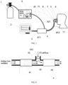
- An embodiment of this invention provides a CO2 and other gas compensation device connected to a universal ventilator, as shown in Figure 1 , including: the device body, which contains a respiratory gas CO2 compensation device 9. Inside the respiratory gas CO2 compensation device 9, an airway 10 is set up. The output end of the airway 10 is connected to a respiratory parameter detection module 4, which is connected to the respiratory terminal 5. Inside the respiratory terminal 5, a proximal pressure sensor 7 and an end-tidal carbon dioxide sensor 8 are installed. The proximal pressure sensor 7 is used to detect the gas pressure inside the respiratory terminal 5, and the end-tidal carbon dioxide sensor 8 is used to detect the end-tidal carbon dioxide value inside the respiratory terminal 5.
- the proximal pressure sensor 7 and the end-tidal carbon dioxide sensor 8 are electrically connected to the respiratory gas CO2 compensation device 9, respectively.
- the respiratory gas CO2 compensation device 9 delivers carbon dioxide into the respiratory terminal 5 based on the detection values of the proximal pressure sensor 7 and the end-tidal carbon dioxide sensor 8 through the respiratory parameter detection module 4.
- the respiratory terminal 5 can be either a mask or a breathing tube intubation.
- the device body includes a respiratory gas CO2 compensation device 9, a respiratory parameter detection module 4, and a respiratory terminal 5.
- the respiratory terminal 5 can be either a mask or a breathing tube intubation for the patient 6 to use for breathing.
- the respiratory gas CO2 compensation device 9 has an airway 10 set up inside, with the input end of the airway 10 able to connect to a gas source, including a carbon dioxide gas source 1 or other active gases needed by the patient 6. To prevent the patient 6 from experiencing respiratory alkalosis when using the ventilator 2, it is necessary to provide carbon dioxide to the patient 6 through the respiratory terminal 5.
- one end of the airway 10 is connected to the carbon dioxide gas source 1, and the other end of the airway 10 is connected to the respiratory parameter detection module 4.
- the output end of the respiratory parameter detection module 4 is connected to the respiratory terminal 5.
- starting the respiratory gas CO2 compensation device 9 can allow carbon dioxide to enter the airway 10 from the input end, then flow into the respiratory parameter detection module 4 along the airway 10.
- the respiratory parameter detection module 4 can monitor the parameters of the carbon dioxide entering the airway 10. Then, the carbon dioxide gas flows into the respiratory terminal 5 through the output end of the respiratory parameter detection module 4, thus providing carbon dioxide to the patient 6 and avoiding respiratory alkalosis in the patient 6.
- the proximal pressure sensor 7 and the end-tidal carbon dioxide sensor 8 are set inside the respiratory terminal 5.
- the proximal pressure sensor 7 can detect the gas pressure inside the respiratory terminal 5.
- the end-tidal carbon dioxide sensor 8 can detect the end-tidal carbon dioxide value inside the respiratory terminal 5, thereby reflecting the patient 6's end-tidal carbon dioxide situation.
- the respiratory gas CO2 compensation device 9 can compensate carbon dioxide gas or other active gases into the respiratory terminal 5.
- the respiratory parameter detection module 4 can monitor the parameters of the incoming carbon dioxide.
- the respiratory gas CO2 compensation device 9, in coordination with the respiratory parameter detection module 4, achieves precise monitoring and adjustment of the incoming carbon dioxide, thereby accurately controlling the amount of carbon dioxide gas needed by the patient 6 and improving the treatment effect of the ventilator 2.
- the airway 10 has an intake filter 441 set near the input end and an exhaust filter 447 set near the output end.
- the device body also includes an adjustment control system, which consists of a control unit, an execution unit, and a detection unit.
- the control unit includes a controller 45, which is set inside the respiratory gas CO2 compensation device 9.
- the controller 45 is electrically connected to the proximal pressure sensor 7 through the first cable 71 and to the end-tidal carbon dioxide sensor 8 through the second cable 81.
- the execution unit includes a solenoid valve 443 and a carbon dioxide regulation proportional valve 444, both set on the airway 10.
- the solenoid valve 443 and the carbon dioxide regulation proportional valve 444 are sequentially set between the intake filter 441 and the exhaust filter 447 and are electrically connected to the controller 45, respectively.
- the detection unit includes an intake pressure sensor 442, a carbon dioxide flowmeter 445, and a carbon dioxide supply pressure sensor 446, sequentially set on the airway 10.
- the intake pressure sensor 442, carbon dioxide flowmeter 445, and carbon dioxide supply pressure sensor 446 are electrically connected to the controller 45, respectively.
- the intake pressure sensor 442 is located between the intake filter 441 and the solenoid valve 443, the carbon dioxide flowmeter 445 is located between the carbon dioxide regulation proportional valve 444 and the exhaust filter 447, and the carbon dioxide supply pressure sensor 446 is located between the carbon dioxide flowmeter 445 and the exhaust filter 447.
- the respiratory parameter detection module 4 includes a compensation mixing tube 42.
- the compensation mixing tube 42 uses a three-way tube.
- the first end of the compensation mixing tube 42 is used for the airflow from the ventilator 2.
- the second end of the compensation mixing tube 42 is connected to the output end of the airway 10 through a connecting tube 421.
- a one-way valve 422 is set inside the second end of the compensation mixing tube 42.
- the third end of the compensation mixing tube 42 is connected to the interior of the respiratory terminal 5 through a gas supply circuit 11.
- the detection unit also includes a flowmeter 41 and a carbon dioxide concentration sensor 43.
- the flowmeter 41 is set near the first end of the compensation mixing tube 42, and the carbon dioxide concentration sensor 43 is set near the third end of the compensation mixing tube 42.
- the flowmeter 41 is electrically connected to the controller 45 through the third cable 411, and the carbon dioxide concentration sensor 43 is electrically connected to the controller 45 through the fourth cable 412.
- the device body also includes an adjustment control system, which consists of a control unit, an execution unit, and a detection unit.
- the control unit can send control signals to the execution unit.
- the execution unit can allow the carbon dioxide gas flow from the carbon dioxide gas source 1 to enter the airway 10 and pass through the airway 10 to enter the compensation mixing tube 42 through its second end.
- the carbon dioxide entering the compensation mixing tube 42 mixes with the breathing airflow, thus achieving carbon dioxide compensation.
- the compensated breathing airflow then flows out from the third end into the respiratory terminal 5 for the patient 6 to breathe.
- the detection unit can obtain detection signals when carbon dioxide passes through the execution unit and the respiratory parameter detection module 4, and sends these detection signals to the control unit.
- the control unit then controls the execution unit based on the detection signals.
- the control unit includes a controller 45 set inside the respiratory gas CO2 compensation device 9.
- the execution unit includes a solenoid valve 443 and a carbon dioxide regulation proportional valve 444 set on the airway 10.
- the opening and closing of the solenoid valve 443 can control the connection and disconnection of the airway 10.
- the carbon dioxide regulation proportional valve 444 can adjust the pressure and flow of the carbon dioxide gas flow inside the airway 10.
- the detection unit includes an intake pressure sensor 442, a carbon dioxide flowmeter 445, a carbon dioxide supply pressure sensor 446 set on the airway 10, and a flowmeter 41 and a carbon dioxide concentration sensor 43 set inside the compensation mixing tube 42.
- the controller 45 starts the solenoid valve 443 to connect the airway 10.
- the carbon dioxide gas flow provided by the carbon dioxide gas source 1 enters the airway 10 after passing through the intake filter 441.
- the intake pressure sensor 442 can detect the intake pressure of the carbon dioxide gas flow entering the airway 10.
- the carbon dioxide flowmeter 445 can detect the flow of the carbon dioxide gas flow inside the airway 10.
- the carbon dioxide supply pressure sensor 446 can detect the pressure of the carbon dioxide gas flow adjusted by the carbon dioxide regulation proportional valve 444.
- the adjusted carbon dioxide gas flow then passes through the exhaust filter 447 and enters the compensation mixing tube 42 through the connecting tube 421.
- a one-way valve 422 is set at the second end of the compensation mixing tube 42.
- the one-way valve 422 prevents the breathing airflow from the ventilator 2 from flowing into the connecting tube 421 through the second end.
- the carbon dioxide gas flow entering the compensation mixing tube 42 can mix with the breathing airflow provided by the ventilator 2, compensating for the carbon dioxide that is less in the original breathing airflow.
- the flowmeter 41 can detect the gas flow inside the compensation mixing tube 42.
- the carbon dioxide concentration sensor 43 can detect the carbon dioxide concentration of the compensated breathing airflow inside the compensation mixing tube 42 and send the detection results to the controller 45.
- the respiratory gas CO2 compensation device 9 is set.
- the respiratory gas CO2 compensation device 9 has a display screen that can display respiratory parameters such as VT, RR, Ti, I:E, FiO2, FiCO2, etc.
- VT tidal volume
- RR ventilation frequency
- Ti inhalation time
- I:E the inhalation to exhalation ratio
- FiO2 represents the fraction of oxygen concentration in the inhaled gas
- FiCO2 represents the fraction of carbon dioxide concentration in the inhaled gas.
- the display screen allows for a direct observation of the above parameters.
- the following is the working process of the device body, with the respiratory gas CO2 compensation device 9 abbreviated as this device. First, set VT, RR, Ti, I:E, FiO2, or FiCO2 on this device. This device calculates the volume of carbon dioxide needed for compensation. During calculation, the volume of carbon dioxide in the exhaled gas can be obtained through the detection value of the end-tidal carbon dioxide sensor 8.
- the volume of carbon dioxide needed for compensation can be obtained by subtracting the volume of carbon dioxide in the exhaled gas from the set volume of carbon dioxide.
- the set volume of carbon dioxide needs to be set according to the needs of different patients 6.
- this device delivers the compensated carbon dioxide according to the set respiratory parameters based on the detection value of the carbon dioxide concentration sensor 43, using a carbon dioxide adjustment algorithm.
- the carbon dioxide adjustment algorithm requires that the sum of the compensated carbon dioxide concentration and the initial detection concentration of the carbon dioxide concentration sensor 43 be within the target carbon dioxide concentration range required in the patient's 6 respiratory airflow.
- the target carbon dioxide concentration range is set according to the needs of different patients 6. Then, this device reads the values of the flowmeter 41 and the proximal pressure sensor 7 to determine whether the delivery of respiratory gas has ended. If it is determined that the delivery has not ended, repeat reading the values.
- this device reads the values of the flowmeter 41 and the proximal pressure sensor 7 to determine whether there is exhaled gas. If it is determined that there is no exhaled gas, repeat reading the values. If it is determined that there is exhaled gas, this device reads the end-tidal carbon dioxide value detected by the end-tidal carbon dioxide sensor 8 and corrects the volume of carbon dioxide needed for compensation based on the volume of carbon dioxide in the exhaled gas.
- the invention automatically adjusts the volume and flow of carbon dioxide gas entering the universal ventilator 2 pipeline based on the gas source, feedback, monitoring, and sampling of the patient's 6 end-tidal carbon dioxide detection information, enhancing the automation, intelligence, and controllability of the device.
- the invention provides high precision carbon dioxide gas concentration needed by the patient 6, achieving effective treatment and medical purposes, and improving treatment outcomes.
- a supporting plate 1001 is arranged outside the airway 10, and several bolt mounting holes are set on the supporting plate 1001.
- an electric heating plate 1002 is arranged between the intake filter 441 and the intake pressure sensor 442.
- the electric heating plate 1002 is electrically connected to the controller 45 and is coaxially arranged inside the airway 10.
- the electric heating plate 1002 has several through holes 1003.
- a fixed shaft 1004 is set. Near the fixed shaft 1004, a fixed ring 1005 and a rotating ring 1006 are arranged in sequence.
- the outer circumference of the fixed ring 1005 is fixedly connected to the inner wall of the airway 10.
- a first convex ring 1007 is set, which is coaxially arranged with the fixed ring 1005.
- the outer circumference of the rotating ring 1006 is rotatably connected to the inner wall of the airway 10.
- a second convex ring 1008 is set, whose inner wall is rotatably connected to the outer wall of the first convex ring 1007.
- baffles 1009 are arranged around the outer circumference of the fixed shaft 1004.
- the baffles 1009 are made of flexible sheet material.
- baffles 1009 are arranged in a circular array around the center of the fixed shaft 1004.
- baffle 1009 One end of the baffle 1009 is connected to the outer circle of the fixed shaft 1004, and the end of the baffle 1009 away from the fixed shaft 1004 is close to the side of the fixed ring 1005 and connected to the inner circumferential surface of the fixed ring 1005.
- the end of the baffle 1009 away from the fixed shaft 1004 and close to the side of the rotating ring 1006 is connected to the inner circumferential surface of the rotating ring 1006.
- a driving component is arranged outside the airway 10, which is used to drive the rotating ring 1006 to rotate.
- the driving component includes: a drive rod 1010 and an electric telescopic rod 1011.
- One end of the drive rod 1010 passes through the side wall of the airway 10 and connects to the outer wall of the rotating ring 1006.
- a long slide slot compatible with the drive rod 1010 is set on the airway 10, and the drive rod 1010 is slidably connected to the long slide slot.
- the end of the drive rod 1010 away from the rotating ring 1006 is equipped with a strip groove 1012.
- the electric telescopic rod 1011 is arranged on the side wall of the supporting plate 1001, and its output end passes through the strip groove 1012 and is equipped with a connecting rod 1013.
- One end of the connecting rod 1013 is hingedly connected to the output end of the electric telescopic rod 1011, and the other end of the connecting rod 1013 is hingedly connected to the inner wall of the upper end of the strip groove 1012.
- Setting multiple through holes 1003 can improve the heating efficiency of the carbon dioxide airflow, making the temperature of the carbon dioxide airflow entering the airway 10 consistent with the temperature of the respiratory airflow flowing out of the ventilator 2.
- the supporting plate 1001 is set on the outer wall of the airway 10, and the supporting plate 1001 can be fixed through bolt installation, thus fixing the airway 10 and improving the stability of the airway 10, avoiding the separation of the airway 10 from the carbon dioxide gas source 1 and affecting the compensation of the carbon dioxide airflow, thereby improving safety and reliability.
- the electric telescopic rod 1011 is activated, which then drives the connecting rod 1013 to move.
- the connecting rod 1013 then drives the drive rod 1010 to move, and the drive rod 1010 drives the rotating ring 1006 to rotate inside the airway 10.
- the rotating ring 1006 rotates, it causes one side of the baffle 1009 to deflect, thereby adjusting the angle of the baffle 1009, changing the direction and flow rate of the passing carbon dioxide airflow, and then finely adjusting it through the carbon dioxide regulation proportional valve 444.
- This not only improves the adjustment precision but also increases the adjustment speed, facilitating rapid adjustments.
- the rotating ring 1006 rotates, the second convex ring 1008 and the first convex ring 1007 also rotate relative to each other.
- the second convex ring 1008 and the first convex ring 1007 cooperate with each other, which can improve the sealing at the connection between the rotating ring 1006 and the fixed ring 1005, avoiding the leakage of carbon dioxide airflow.
- FIG. 8 Based on Embodiment 3, as shown in Figure 8 , several arc holes 1014 are opened on the rotating ring 1006, and several arc holes 1014 are arranged in a circular array around the center of the rotating ring 1006.
- a guide column 1015 is slidably arranged inside the arc hole 1014, one end of the guide column 1015 is fixedly connected to the side of the fixed ring 1005 close to the rotating ring 1006, and the other end of the guide column 1015 extends outside the arc hole 1014 and is equipped with a limit block 1016.
- the working principle and beneficial effects of the above technical solution are as follows:
- the arc hole 1014 is coaxially arranged with the rotating ring 1006.
- the arc hole 1014 can slide along the guide column 1015, improving the stability of the rotation of the rotating ring 1006.
- the limit block 1016 can limit the rotating ring 1006 to prevent it from separating from the fixed ring 1005, thereby extending the service life of the device.
- the invention also provides a CO2 and other gas compensation system connected to a universal ventilator, including the CO2 and other gas compensation device connected to a universal ventilator mentioned above, as well as the ventilator 2 and the carbon dioxide gas source 1.
- the carbon dioxide gas source 1 is connected to the input end of the airway 10 of the respiratory gas CO2 compensation device 9 through the intake pipe, and the ventilator 2 is connected to the compensation mixing tube 42 through the respiratory circuit 3.
- the device body of the invention can be connected to all existing universal ventilators 2 on the market, enhancing their functionality and increasing their applicability.
- the device body can provide ports for supplying carbon dioxide and other active gases to patients 6 for all ventilators 2 on the market, thus expanding the functionality of the ventilator 2, enabling it to provide the required carbon dioxide for patients 6, avoiding respiratory alkalosis in patients 6, greatly improving the therapeutic effect of the ventilator 2, and the device body can adjust the carbon dioxide supply amount and automatically regulate the flow supply according to the changes in airflow parameters such as flow and pressure in the respiratory circuit 3 of the ventilator 2, the proximal pressure, and the end-tidal carbon dioxide value, improving the intelligence and automation level of the system.
Landscapes
- Health & Medical Sciences (AREA)
- Pulmonology (AREA)
- Heart & Thoracic Surgery (AREA)
- Engineering & Computer Science (AREA)
- Anesthesiology (AREA)
- Biomedical Technology (AREA)
- Emergency Medicine (AREA)
- Hematology (AREA)
- Life Sciences & Earth Sciences (AREA)
- Animal Behavior & Ethology (AREA)
- General Health & Medical Sciences (AREA)
- Public Health (AREA)
- Veterinary Medicine (AREA)
- Measurement Of The Respiration, Hearing Ability, Form, And Blood Characteristics Of Living Organisms (AREA)
Applications Claiming Priority (2)
| Application Number | Priority Date | Filing Date | Title |
|---|---|---|---|
| CN202310804800.8A CN116688300B (zh) | 2023-07-03 | 2023-07-03 | 一种连接通用呼吸机的co2及其它气体补偿装置及系统 |
| PCT/CN2024/074141 WO2025007554A1 (zh) | 2023-07-03 | 2024-01-26 | 一种连接通用呼吸机的co2及其它气体补偿装置及系统 |
Publications (4)
| Publication Number | Publication Date |
|---|---|
| EP4512447A4 EP4512447A4 (de) | 2025-02-26 |
| EP4512447A1 true EP4512447A1 (de) | 2025-02-26 |
| EP4512447B1 EP4512447B1 (de) | 2025-11-12 |
| EP4512447C0 EP4512447C0 (de) | 2025-11-12 |
Family
ID=87841140
Family Applications (1)
| Application Number | Title | Priority Date | Filing Date |
|---|---|---|---|
| EP24710585.1A Active EP4512447B1 (de) | 2023-07-03 | 2024-01-26 | Co2-gaskompensationsvorrichtung und system |
Country Status (4)
| Country | Link |
|---|---|
| US (1) | US20250010005A1 (de) |
| EP (1) | EP4512447B1 (de) |
| CN (1) | CN116688300B (de) |
| WO (1) | WO2025007554A1 (de) |
Families Citing this family (4)
| Publication number | Priority date | Publication date | Assignee | Title |
|---|---|---|---|---|
| CN116688300B (zh) * | 2023-07-03 | 2024-02-06 | 广州蓝仕威克医疗科技有限公司 | 一种连接通用呼吸机的co2及其它气体补偿装置及系统 |
| CN117815507A (zh) * | 2024-01-15 | 2024-04-05 | 山东大学齐鲁医院 | 一种快速提高co2分压的套件 |
| CN118576841A (zh) * | 2024-06-14 | 2024-09-03 | 广州蓝仕威克医疗科技有限公司 | 一种气体中毒呼吸机气路结构、装置及气路流量调节方法 |
| CN120324860B (zh) * | 2025-06-17 | 2025-08-29 | 十堰市太和医院(湖北医药学院附属医院) | 一种高效呼吸康复训练辅助装置 |
Family Cites Families (20)
| Publication number | Priority date | Publication date | Assignee | Title |
|---|---|---|---|---|
| US5320093A (en) * | 1990-12-21 | 1994-06-14 | Brigham And Women's Hospital | Rapid anesthesia emergence system using closed-loop PCO2 control |
| US5386833A (en) * | 1993-12-23 | 1995-02-07 | Biochem International, Inc. | Method for calibrating a carbon dioxide monitor |
| US20050288602A1 (en) * | 2004-06-04 | 2005-12-29 | Vacumetrics Inc. | Device and method for determining respiratory quotient without measuring lung ventilation |
| SE529989C2 (sv) * | 2004-09-03 | 2008-01-29 | Ric Investments Llc | Gasregulator |
| EP1951347B1 (de) * | 2005-11-16 | 2017-01-11 | TreyMed, Inc. | Seitenstrom-atemgas-überwachungssystem |
| CN103536995B (zh) | 2012-07-09 | 2017-04-12 | 深中海医疗用品(深圳)有限公司 | 一种吸氧面罩 |
| US8973580B1 (en) * | 2014-01-09 | 2015-03-10 | Osborne Williams | Portable manual ventilation device |
| ES2966576T3 (es) * | 2015-06-11 | 2024-04-23 | Sunmed Group Holdings Llc | Máscara de ventilación |
| JP7086074B2 (ja) * | 2016-12-08 | 2022-06-17 | マケット・クリティカル・ケア・アーベー | Co2除去のためのシステム |
| EP3400984A1 (de) * | 2017-05-08 | 2018-11-14 | Philippe Goutorbe | Systeme und verfahren zur automatischen einstellung einer bestimmten zufuhr von fio2 aus einem cpap, niv oder anderem ventilatorsystem |
| CN208710724U (zh) * | 2018-05-16 | 2019-04-09 | 江苏大学附属医院 | 一种呼吸装置 |
| CN109405433A (zh) * | 2018-09-17 | 2019-03-01 | 阜南县东方柳编工艺品有限公司 | 一种木板烘干设备 |
| US11596326B2 (en) * | 2019-12-06 | 2023-03-07 | Koninklijke Philips N.V. | Systems and methods for metabolic monitoring |
| CN113117206A (zh) * | 2019-12-31 | 2021-07-16 | 罗远明 | 用于防治高原反应的吸入装置 |
| CN111658932A (zh) * | 2020-07-21 | 2020-09-15 | 南京鼓楼医院 | 一种用于自主呼吸激发试验的呼吸器 |
| US20220241533A1 (en) * | 2021-02-01 | 2022-08-04 | Logan Henry Fairchild | Oxygen mask with carbon dioxide monitor |
| CN114733024B (zh) * | 2022-04-26 | 2022-11-15 | 广州蓝仕威克医疗科技有限公司 | 一种带有二氧化碳补偿功能的呼吸装置 |
| CN114870179B (zh) * | 2022-05-25 | 2023-04-18 | 广州蓝仕威克医疗科技有限公司 | 一种动态监控与调控二氧化碳分压的麻醉呼吸机装置 |
| CN219128823U (zh) * | 2022-12-28 | 2023-06-06 | 河南零碳技术研究院有限公司 | 一种垃圾燃烧尾气处理系统 |
| CN116688300B (zh) * | 2023-07-03 | 2024-02-06 | 广州蓝仕威克医疗科技有限公司 | 一种连接通用呼吸机的co2及其它气体补偿装置及系统 |
-
2023
- 2023-07-03 CN CN202310804800.8A patent/CN116688300B/zh active Active
-
2024
- 2024-01-26 EP EP24710585.1A patent/EP4512447B1/de active Active
- 2024-01-26 WO PCT/CN2024/074141 patent/WO2025007554A1/zh active Pending
- 2024-04-29 US US18/648,488 patent/US20250010005A1/en active Pending
Also Published As
| Publication number | Publication date |
|---|---|
| CN116688300A (zh) | 2023-09-05 |
| WO2025007554A1 (zh) | 2025-01-09 |
| EP4512447B1 (de) | 2025-11-12 |
| US20250010005A1 (en) | 2025-01-09 |
| CN116688300B (zh) | 2024-02-06 |
| EP4512447C0 (de) | 2025-11-12 |
Similar Documents
| Publication | Publication Date | Title |
|---|---|---|
| EP4512447A1 (de) | Co2- und andere gaskompensationsvorrichtung und system, das mit einem allgemeinen ventilator verbunden ist | |
| US4188946A (en) | Controllable partial rebreathing anesthesia circuit and respiratory assist device | |
| RU2455031C2 (ru) | Аппарат для вентиляции и способ, позволяющий пациенту говорить с обратным клапаном трахеостомической трубки или без него | |
| JPH05245204A (ja) | 医療用ベンチレーター | |
| US20070144516A1 (en) | Ventilator adaptable for use with either a dual-limb circuit or a single-limb circuit | |
| CN106492321B (zh) | 一种呼吸机 | |
| CN101337101A (zh) | 麻醉机和呼吸机的通气系统及压力监控方法 | |
| JPH08503863A (ja) | 呼吸補助装置 | |
| JPH1085334A (ja) | ベンチレータまたはレスピレータの流動抵抗を補償するための装置 | |
| CN206837209U (zh) | 一种呼吸机 | |
| EP4085955A1 (de) | Medizinisches belüftungssystem | |
| EP2572748A1 (de) | Vorrichtung und Verfahren zur Bereitstellung eines Atemgases zur Atemunterstützung eines Menschen und Anordnung zur Versorgung der Lunge eines Menschen mit Inspirationsgas | |
| JP2024503250A (ja) | 一体化された酸素送達を有するベンチレータシステムおよび関連付けられたデバイスおよび方法 | |
| CN218652679U (zh) | 人工气道、人工气道的输出压力调节装置 | |
| CN117504077A (zh) | 一种呼吸机及医疗设备 | |
| CN116899066A (zh) | 一种氧气组件及使用该组件的呼吸机 | |
| EP3939644B1 (de) | Transportierbares lungenbeatmungsgerät | |
| CN113769214A (zh) | 一种呼吸机控制系统 | |
| CN221998545U (zh) | 一种高频振荡呼吸机及其气路结构 | |
| CN213555233U (zh) | 一种可调节呼气末正压及氧浓度的自主呼吸锻炼器械 | |
| CN112450883B (zh) | 一种气管切开术后语音训练康复装置 | |
| CN222488449U (zh) | 一种用于急救一体机的呼吸装置及急救一体机 | |
| EP4539910B1 (de) | Lungenbeatmungsgerät | |
| US20240316298A1 (en) | Device for calibrating the sensors of an no delivery apparatus | |
| CN220588726U (zh) | 氧浓度检测装置 |
Legal Events
| Date | Code | Title | Description |
|---|---|---|---|
| STAA | Information on the status of an ep patent application or granted ep patent |
Free format text: STATUS: UNKNOWN |
|
| STAA | Information on the status of an ep patent application or granted ep patent |
Free format text: STATUS: THE INTERNATIONAL PUBLICATION HAS BEEN MADE |
|
| PUAI | Public reference made under article 153(3) epc to a published international application that has entered the european phase |
Free format text: ORIGINAL CODE: 0009012 |
|
| STAA | Information on the status of an ep patent application or granted ep patent |
Free format text: STATUS: REQUEST FOR EXAMINATION WAS MADE |
|
| STAA | Information on the status of an ep patent application or granted ep patent |
Free format text: STATUS: EXAMINATION IS IN PROGRESS |
|
| 17P | Request for examination filed |
Effective date: 20240319 |
|
| A4 | Supplementary search report drawn up and despatched |
Effective date: 20250120 |
|
| AK | Designated contracting states |
Kind code of ref document: A1 Designated state(s): AL AT BE BG CH CY CZ DE DK EE ES FI FR GB GR HR HU IE IS IT LI LT LU LV MC ME MK MT NL NO PL PT RO RS SE SI SK SM TR |
|
| 17Q | First examination report despatched |
Effective date: 20250205 |
|
| GRAP | Despatch of communication of intention to grant a patent |
Free format text: ORIGINAL CODE: EPIDOSNIGR1 |
|
| STAA | Information on the status of an ep patent application or granted ep patent |
Free format text: STATUS: GRANT OF PATENT IS INTENDED |
|
| INTG | Intention to grant announced |
Effective date: 20250704 |
|
| GRAS | Grant fee paid |
Free format text: ORIGINAL CODE: EPIDOSNIGR3 |
|
| GRAA | (expected) grant |
Free format text: ORIGINAL CODE: 0009210 |
|
| STAA | Information on the status of an ep patent application or granted ep patent |
Free format text: STATUS: THE PATENT HAS BEEN GRANTED |
|
| DAV | Request for validation of the european patent (deleted) | ||
| DAX | Request for extension of the european patent (deleted) | ||
| AK | Designated contracting states |
Kind code of ref document: B1 Designated state(s): AL AT BE BG CH CY CZ DE DK EE ES FI FR GB GR HR HU IE IS IT LI LT LU LV MC ME MK MT NL NO PL PT RO RS SE SI SK SM TR |
|
| REG | Reference to a national code |
Ref country code: CH Ref legal event code: F10 Free format text: ST27 STATUS EVENT CODE: U-0-0-F10-F00 (AS PROVIDED BY THE NATIONAL OFFICE) Effective date: 20251112 Ref country code: GB Ref legal event code: FG4D |
|
| REG | Reference to a national code |
Ref country code: DE Ref legal event code: R096 Ref document number: 602024001258 Country of ref document: DE |
|
| REG | Reference to a national code |
Ref country code: IE Ref legal event code: FG4D |
|
| U01 | Request for unitary effect filed |
Effective date: 20251204 |
|
| U07 | Unitary effect registered |
Designated state(s): AT BE BG DE DK EE FI FR IT LT LU LV MT NL PT RO SE SI Effective date: 20251210 |
|
| U20 | Renewal fee for the european patent with unitary effect paid |
Year of fee payment: 3 Effective date: 20260130 |