EP4509206A1 - Crossflow-filtrationseinheit zur kontinuierlichen diafiltration - Google Patents
Crossflow-filtrationseinheit zur kontinuierlichen diafiltration Download PDFInfo
- Publication number
- EP4509206A1 EP4509206A1 EP24207481.3A EP24207481A EP4509206A1 EP 4509206 A1 EP4509206 A1 EP 4509206A1 EP 24207481 A EP24207481 A EP 24207481A EP 4509206 A1 EP4509206 A1 EP 4509206A1
- Authority
- EP
- European Patent Office
- Prior art keywords
- retentate
- diafiltration
- gap
- filtration unit
- feed liquid
- Prior art date
- Legal status (The legal status is an assumption and is not a legal conclusion. Google has not performed a legal analysis and makes no representation as to the accuracy of the status listed.)
- Granted
Links
Images


Classifications
-
- B—PERFORMING OPERATIONS; TRANSPORTING
- B01—PHYSICAL OR CHEMICAL PROCESSES OR APPARATUS IN GENERAL
- B01D—SEPARATION
- B01D61/00—Processes of separation using semi-permeable membranes, e.g. dialysis, osmosis or ultrafiltration; Apparatus, accessories or auxiliary operations specially adapted therefor
- B01D61/14—Ultrafiltration; Microfiltration
- B01D61/149—Multistep processes comprising different kinds of membrane processes selected from ultrafiltration or microfiltration
-
- A—HUMAN NECESSITIES
- A23—FOODS OR FOODSTUFFS; TREATMENT THEREOF, NOT COVERED BY OTHER CLASSES
- A23C—DAIRY PRODUCTS, e.g. MILK, BUTTER OR CHEESE; MILK OR CHEESE SUBSTITUTES; PREPARATION THEREOF
- A23C9/00—Milk preparations; Milk powder or milk powder preparations
- A23C9/14—Milk preparations; Milk powder or milk powder preparations in which the chemical composition of the milk is modified by non-chemical treatment
- A23C9/142—Milk preparations; Milk powder or milk powder preparations in which the chemical composition of the milk is modified by non-chemical treatment by dialysis, reverse osmosis or ultrafiltration
-
- A—HUMAN NECESSITIES
- A61—MEDICAL OR VETERINARY SCIENCE; HYGIENE
- A61M—DEVICES FOR INTRODUCING MEDIA INTO, OR ONTO, THE BODY; DEVICES FOR TRANSDUCING BODY MEDIA OR FOR TAKING MEDIA FROM THE BODY; DEVICES FOR PRODUCING OR ENDING SLEEP OR STUPOR
- A61M1/00—Suction or pumping devices for medical purposes; Devices for carrying-off, for treatment of, or for carrying-over, body-liquids; Drainage systems
- A61M1/34—Filtering material out of the blood by passing it through a membrane, i.e. hemofiltration or diafiltration
- A61M1/3413—Diafiltration
- A61M1/3417—Diafiltration using distinct filters for dialysis and ultra-filtration
-
- B—PERFORMING OPERATIONS; TRANSPORTING
- B01—PHYSICAL OR CHEMICAL PROCESSES OR APPARATUS IN GENERAL
- B01D—SEPARATION
- B01D61/00—Processes of separation using semi-permeable membranes, e.g. dialysis, osmosis or ultrafiltration; Apparatus, accessories or auxiliary operations specially adapted therefor
- B01D61/14—Ultrafiltration; Microfiltration
- B01D61/16—Feed pretreatment
-
- B—PERFORMING OPERATIONS; TRANSPORTING
- B01—PHYSICAL OR CHEMICAL PROCESSES OR APPARATUS IN GENERAL
- B01D—SEPARATION
- B01D61/00—Processes of separation using semi-permeable membranes, e.g. dialysis, osmosis or ultrafiltration; Apparatus, accessories or auxiliary operations specially adapted therefor
- B01D61/14—Ultrafiltration; Microfiltration
- B01D61/22—Controlling or regulating
-
- B—PERFORMING OPERATIONS; TRANSPORTING
- B01—PHYSICAL OR CHEMICAL PROCESSES OR APPARATUS IN GENERAL
- B01D—SEPARATION
- B01D61/00—Processes of separation using semi-permeable membranes, e.g. dialysis, osmosis or ultrafiltration; Apparatus, accessories or auxiliary operations specially adapted therefor
- B01D61/24—Dialysis ; Membrane extraction
- B01D61/32—Controlling or regulating
-
- B—PERFORMING OPERATIONS; TRANSPORTING
- B01—PHYSICAL OR CHEMICAL PROCESSES OR APPARATUS IN GENERAL
- B01D—SEPARATION
- B01D63/00—Apparatus in general for separation processes using semi-permeable membranes
- B01D63/08—Flat membrane modules
- B01D63/082—Flat membrane modules comprising a stack of flat membranes
- B01D63/084—Flat membrane modules comprising a stack of flat membranes at least one flow duct intersecting the membranes
-
- A—HUMAN NECESSITIES
- A61—MEDICAL OR VETERINARY SCIENCE; HYGIENE
- A61M—DEVICES FOR INTRODUCING MEDIA INTO, OR ONTO, THE BODY; DEVICES FOR TRANSDUCING BODY MEDIA OR FOR TAKING MEDIA FROM THE BODY; DEVICES FOR PRODUCING OR ENDING SLEEP OR STUPOR
- A61M2205/00—General characteristics of the apparatus
- A61M2205/33—Controlling, regulating or measuring
- A61M2205/3331—Pressure; Flow
-
- B—PERFORMING OPERATIONS; TRANSPORTING
- B01—PHYSICAL OR CHEMICAL PROCESSES OR APPARATUS IN GENERAL
- B01D—SEPARATION
- B01D2311/00—Details relating to membrane separation process operations and control
- B01D2311/04—Specific process operations in the feed stream; Feed pretreatment
-
- B—PERFORMING OPERATIONS; TRANSPORTING
- B01—PHYSICAL OR CHEMICAL PROCESSES OR APPARATUS IN GENERAL
- B01D—SEPARATION
- B01D2311/00—Details relating to membrane separation process operations and control
- B01D2311/25—Recirculation, recycling or bypass, e.g. recirculation of concentrate into the feed
-
- B—PERFORMING OPERATIONS; TRANSPORTING
- B01—PHYSICAL OR CHEMICAL PROCESSES OR APPARATUS IN GENERAL
- B01D—SEPARATION
- B01D2311/00—Details relating to membrane separation process operations and control
- B01D2311/25—Recirculation, recycling or bypass, e.g. recirculation of concentrate into the feed
- B01D2311/252—Recirculation of concentrate
- B01D2311/2523—Recirculation of concentrate to feed side
-
- B—PERFORMING OPERATIONS; TRANSPORTING
- B01—PHYSICAL OR CHEMICAL PROCESSES OR APPARATUS IN GENERAL
- B01D—SEPARATION
- B01D2313/00—Details relating to membrane modules or apparatus
- B01D2313/14—Specific spacers
- B01D2313/143—Specific spacers on the feed side
-
- B—PERFORMING OPERATIONS; TRANSPORTING
- B01—PHYSICAL OR CHEMICAL PROCESSES OR APPARATUS IN GENERAL
- B01D—SEPARATION
- B01D2315/00—Details relating to the membrane module operation
- B01D2315/06—Submerged-type; Immersion type
-
- B—PERFORMING OPERATIONS; TRANSPORTING
- B01—PHYSICAL OR CHEMICAL PROCESSES OR APPARATUS IN GENERAL
- B01D—SEPARATION
- B01D2315/00—Details relating to the membrane module operation
- B01D2315/10—Cross-flow filtration
-
- B—PERFORMING OPERATIONS; TRANSPORTING
- B01—PHYSICAL OR CHEMICAL PROCESSES OR APPARATUS IN GENERAL
- B01D—SEPARATION
- B01D2317/00—Membrane module arrangements within a plant or an apparatus
- B01D2317/02—Elements in series
- B01D2317/022—Reject series
-
- B—PERFORMING OPERATIONS; TRANSPORTING
- B01—PHYSICAL OR CHEMICAL PROCESSES OR APPARATUS IN GENERAL
- B01D—SEPARATION
- B01D2319/00—Membrane assemblies within one housing
- B01D2319/06—Use of membranes of different materials or properties within one module
Definitions
- the present invention relates to a crossflow filtration unit for the continuous diafiltration of a feed liquid to obtain a retentate and a permeate, a corresponding method for diafiltration and the use of the crossflow filtration unit.
- crossflow filtration which can also be referred to as cross-flow or tangential flow filtration
- a feed liquid to be filtered flows tangentially over the surface of a filter material, which is usually a membrane, and is split into a retentate (concentrate) and a permeate (filtrate) of different compositions.
- the retentate flows over the surface of the filter material and can be removed after only one overflow ("single-pass" operation), but can also be recycled so that it flows over the membrane surface repeatedly.
- the permeate flows through the membrane perpendicular to the surface and is then discharged.
- Target substances to be recovered can be contained in the permeate (permeate substances) and/or the retentate (retentate substances).
- Crossflow filtration units are often used in the form of filter cassettes, such as those used in DE-PS 34 41 249
- Filter cassettes comprise several adjacent crossflow filtration units (filter cells), which usually consist of repeated arrangements of a retentate gap for the feed liquid or retentate to be filtered, a flat membrane layer and a permeate collection gap.
- the permeate collection gap of the preceding filter cell is separated from the retentate gap of the next filter cell by another flat membrane layer.
- Each retentate gap is fluidically connected (communicating) to an inlet for the feed liquid to be filtered and to an outlet for the retentate, and each permeate collection gap is connected to an outlet for the permeate in a fluid-conducting manner.
- a feed liquid is separated into a retentate and a permeate.
- this separation is combined with a step of adding a diafiltration medium to the feed liquid/retentate.
- This makes it possible, for example, to free a joint solution of target substance(s) and one or more other substances from the other substances.
- diafiltration of a protein solution can be used to achieve buffer exchange or desalination, optionally combined with concentration.
- volume-variable diafiltration sometimes referred to as “discontinuous” diafiltration in the prior art
- volume-constant diafiltration sometimes referred to as “continuous” diafiltration in the prior art
- variable-volume diafiltration In variable-volume diafiltration, filtration steps and steps of adding a diafiltration medium alternate. Consequently, the volume of the retentate fluctuates over the course of this process variant, which is where the term "discontinuous diafiltration" comes from.
- constant-volume diafiltration the volume of the retentate is kept constant by both the filtration and the addition of the diafiltration medium taking place continuously. However, the addition of the feed liquid takes place discontinuously and usually only at the beginning of the process. Therefore, both variable-volume and constant-volume diafiltration are discontinuous processes.
- a discontinuous diafiltration process a fixed volume of feed liquid must be subjected to a complete process run before a new process run can be started ("batch" process). For reasons of economy and efficiency, continuous processes in which material flows can be continuously added and removed are preferable to discontinuous processes. Therefore, there is a need for a continuous di iafi ltration process.
- the present invention is therefore based on the object of providing a crossflow filtration unit which is suitable for continuous diafiltration.
- the present invention relates to a crossflow filtration unit for continuous diafiltration of a feed liquid to obtain a retentate and a permeate, at least comprising a diafiltration gap, a flat first filter material, a retentate gap, a flat second filter material and a permeate collection gap, arranged such that the flat first filter material separates the diafiltration gap and the retentate gap from one another and the flat second filter material separates the retentate gap and the permeate collection gap from one another, wherein the diafiltration gap is fluidically connected to at least one inlet for the diafiltration medium, the retentate gap is fluidically connected to at least one inlet for the feed liquid and to at least one outlet for the retentate and the permeate collection gap is fluidically connected to at least one outlet for the permeate, and wherein the pore size or the molecular weight exclusion limit of the flat first filter material is at least as large as the pore size or the molecular weight exclusion limit of the flat
- the flat first filter material has a molecular weight cut-off (MWCO) in the range of 30 kDa to 1500 kDa.
- the flat second filter material preferably has a molecular weight cut-off in the range of 5 kDa to 1500 kDa.
- the molecular weight cut-off can be determined according to US standard ASTM E1343-90 (“Standard test method for molecular weight cutoff evaluation of flat sheet ultrafiltration membranes”).
- the flat first filter material preferably has a pore size of 0.01 to 50 ⁇ m, preferably 0.01 to 0.5 ⁇ m.
- the flat second filter material preferably has a pore size of less than 0.01 ⁇ m.
- the pore size which is also referred to as the "largest pore diameter" or "d p " and in English as “maximum pore size" can be determined according to US standard ASTM F316-03 TEST METHOD A ("Standard test methods for pore size characteristics of membrane filters by bubble point and mean flow pore test").
- the diafiltration medium is introduced between crossflow filtration units connected in series or the feed liquid is diluted with diafiltration medium, combined with upstream or subsequent concentration by crossflow filtration.
- the crossflow filtration unit according to the invention makes it possible to introduce a certain amount of diafiltration medium into the retentate gap for optimal diafiltration by means of suitable pressurization.
- the volume of the diafiltration medium can be 0.1 to 15 times the volume of the feed liquid.
- the diafiltration medium is preferably introduced into the retentate gap in such a way that the entire available area of the flat first filter material is covered with the diafiltration medium.
- the crossflow filtration unit according to the invention can achieve an improved diafiltration result compared to discontinuous diafiltration.
- the invention leads to a reduction in process times and equipment costs.
- both feed liquid and diafiltration medium are added continuously so that the process does not have to be interrupted.
- the crossflow filtration unit according to the invention therefore enables efficient and economical process management.
- fluids such as liquids, emulsions, suspensions, drinks such as beer, wine, juice, water, milk and whey, beer wort, industrial and waste water, solutions in the pharmaceutical, medical, cosmetic, chemical, biotechnology, genetic engineering, environmental protection and laboratory sectors can be used as feed liquids and diafiltered. They can be used for recovering valuable materials, separating substances, for example macromolecules and biomolecules, for depyrogenation and sterilization of solutions, for separating pollutants from fluids, for (dia)filtration and concentration of biological solutions, for separating microorganisms such as bacteria, yeasts, viruses and cell components, for desalination of protein solutions and other biological media.
- the crossflow filtration unit according to the invention can be used particularly advantageously for filtration, diafiltration, concentration (reduction of the solvent or water content), and/or changing the ion composition (e.g. desalination or buffer exchange) of a solution, preferably a protein solution.
- concentration reduction of the solvent or water content
- ion composition e.g. desalination or buffer exchange
- feed liquid and retentate can be used synonymously for the liquid in the retentate gap.
- flat indicates that the respective filter material lies essentially in a single plane. Preferably, all filter materials lie essentially in planes that are largely parallel to one another.
- the planar first Filter material is a first filtration membrane.
- the flat second filter material is preferably a second filtration membrane.
- the flat first filter material is a first filtration membrane and the flat second filter material is a second filtration membrane.
- a porous membrane in the ultrafiltration and microfiltration range is particularly suitable as the first filter material.
- An ultrafiltration membrane can advantageously be used as the second filter material. This design allows a certain amount of diafiltration medium to be introduced into the retentate gap by means of suitable pressure application for optimal diafiltration. When pressure is applied, the entire available surface of the flat first filter material is covered with the diafiltration medium.
- the ultrafiltration membranes are characterized by pore sizes of less than 0.01 ⁇ m, or by molecular weight exclusion limits that are approximately in the molecular weight range of 5 to 1500 kDa, while the microfiltration membranes have pore sizes in the range of 0.01 to 50 ⁇ m, preferably 0.01 to 0.5 ⁇ m, or molecular weight exclusion limits of 30 to 1500 kDa.
- the filtration membranes can consist, for example, of polyvinylidene fluoride, cellulose and its derivatives, polyethersulfone or polysulfone, with cross-linked cellulose hydrate being particularly preferred.
- the inlet for the feed liquid is arranged in a first edge region of the crossflow filtration unit and the outlet for the retentate is arranged in a second edge region of the crossflow filtration unit, which is opposite the first edge region.
- This arrangement defines a largely uniform flow direction of the retentate from the inlet for the feed liquid as the starting point to the outlet for the retentate as the end point.
- the flow direction of the retentate is thus largely parallel to the flow path along the flat filter material, i.e. essentially without deflections, which ensures a stable and reliable flow of the retentate through the Crossflow filtration unit can be guaranteed.
- the inlet for the diafiltration medium is installed in the first edge area of the crossflow filtration unit.
- the outlet for the permeate is arranged in the second edge region of the crossflow filtration unit.
- at least one outlet for the permeate is arranged in both the first and the second edge region of the crossflow filtration unit.
- the outlets for the permeate are alternatively or additionally arranged in the third and/or fourth edge region of the crossflow filtration unit.
- the third edge region is on the left side of the flow direction.
- the fourth edge region is accordingly on the right side and is thus opposite the third edge region.
- the first edge region comprises the outer third of the length of the filtration unit against the flow direction.
- the second edge region comprises the outer third of the length of the filtration unit along the flow direction.
- the edge regions particularly preferably comprise the respective outer 20%, even more preferably the respective outer 10% and most preferably the respective outer 3%.
- the inlets and outlets can be placed in such a way that the feed liquid already enters the retentate gap in the direction of flow and leaves it in the direction of flow.
- the outlet for the permeate can be placed in such a way that the permeate leaves the permeate collection gap in the direction of flow and/or the inlet for the diafiltration medium can be placed in such a way that it enters the diafiltration gap in the direction of flow.
- the inlets and outlets are placed in such a way that the diafiltration medium enters the diafiltration gap perpendicular to the direction of flow and the feed liquid initially enters the retentate gap perpendicular to the direction of flow and leaves it as retentate perpendicular to the direction of flow.
- Such placement of the inlets and outlets facilitates the arrangement of a plurality of the filtration units according to the invention to form a filter cassette.
- the crossflow filtration unit has a plurality of inlets for the feed liquid, a plurality of outlets for the retentate and a plurality of outlets for the permeate.
- the free volume of the diafiltration gap and/or the retentate gap decreases in the flow direction from the inlet for the feed liquid to the outlet for the retentate. Due to the decreasing volume(s) and the flatness of the filter materials, the crossflow filtration unit has a low pressure loss and a flow path of the diafiltration medium and the retentate that is essentially free of deflections. This makes it possible to increase the surface performance of the crossflow diafiltration unit and to operate the crossflow diafiltration unit in "single-pass" mode (only a single pass of the retentate takes place without circulation).
- the reduction in the free volume along the flow direction is achieved by the width of the diafiltration gap and/or the width of the retentate gap decreasing in the flow direction.
- the width runs along the flat first filter material and perpendicular to the flow direction.
- the width of the entire crossflow filtration unit decreases in the flow direction.
- the retentate gap or the crossflow filtration unit is trapezoidal in a plan view along a normal to the plane in which the flat first filter material lies.
- the basic trapezoidal shape of the diafiltration gap and/or the retentate gap or the crossflow filtration unit can be unequal-sided, for example right-angled, and is preferably isosceles.
- the height of the diafiltration gap and/or the retentate gap or the crossflow filtration unit can decrease in the flow direction.
- the diafiltration gap and/or the retentate gap can be wedge-shaped.
- the height of the diafiltration gap and/or the retentate gap or the crossflow filtration unit runs perpendicular to the flat first filter material and perpendicular to the flow direction.
- the width, length and height of the crossflow filtration unit There are no particular restrictions with regard to the width, length and height of the crossflow filtration unit.
- the length runs parallel to the flow direction and along the flat first filter material.
- the crossflow filtration unit preferably has a length of at least 50 mm, preferably at least 150 mm, particularly preferably 500 mm, particularly preferably 750 mm or more. Such a length can be achieved, for example, by connecting several, for example at least 2, at least 3 or at least 4, crossflow filtration units in series. A longer length can achieve particularly high efficiency.
- the free volume of the permeate collection gap changes in the flow direction.
- the free volume of the permeate collection gap decreases in the flow direction. This allows For example, the external dimensions of the filtration cassette are retained.
- Free volume decreasing in the flow direction means that a cross-sectional area A 1 through which the diafiltration medium or the retentate can flow and which lies in a plane having a normal parallel to the flow direction, and a corresponding cross-sectional area A 2 which is parallel to A 1 and further away from the inlet for the diafiltration medium or the feed liquid than A 1 , wherein the surface area A 1 through which the diafiltration medium or the retentate can flow is greater than A 2 , exist and no correspondingly defined planes A 1 ' and A 2 ' exist for which the surface area of A 1 ' is smaller than that of A 2 '.
- the decrease in free volume can be steady (for all A 1 and A 2 , A 1 ⁇ A 2 ) or continuous (for all A 1 and A 2 , A 1 > A 2 ). It is also possible that the volume decrease is discontinuous, that is, that at least one discontinuous decrease or jump in the cross-sectional area occurs along the flow direction.
- the change in the free volume of the retentate gap in the flow direction is preferably in the range from 20 to 1 to 1.2 to 1, preferably 10 to 1, depending on the filtration task.
- the "change in the free volume of the retentate gap in the flow direction" is understood to mean the ratio of the cross-sectional area A 1 at the inlet for the feed liquid to the cross-sectional area A 2 at the outlet for the retentate.
- the thickness of the diafiltration gap and/or the thickness of the retentate gap and optionally the thickness of the permeate collection gap decreases in the flow direction.
- the diafiltration gap, the retentate gap and the permeate collection gap are usually kept open by spacers for the corresponding media.
- a flat spacer is/are attached in the diafiltration gap and/or in the retentate gap of the crossflow filtration unit such that the free volume of the retentate gap decreases in the flow direction.
- Suitable spacers for crossflow filtration units are known in the art and can be used in the diafiltration gap, retentate gap and/or permeate collection gap of the crossflow filtration unit according to the invention.
- the spacers are modified according to the invention so that their volume increases in the flow direction in order to achieve a volume decrease in the free volume available for the diafiltration medium or the retentate.
- Preferred spacers can be textile materials made of organic or non-organic materials, such as woven fabrics, knitted fabrics, nonwovens or extruded nets.
- the spacer may be a non-planar plate.
- the non-planar plate may be a plate having at least one non-planar main surface.
- the main surfaces of a plate are the opposing surfaces with the largest surface area.
- the at least one non-planar main surface may have unevenness in the form of a corrugated or jagged surface.
- the uneven surface may have protruding elements such as cones (truncated cones), pyramids (truncated pyramids), knobs or other geometric figures.
- the non-planar plate may also be in a corrugated or jagged form similar to corrugated sheet metal, with the waves or jagged edges preferably extending parallel to the flow direction. Suitable materials for the non-planar plate are the same as those listed below for spacers in the form of an open-mesh matrix.
- the spacer consists of an open-mesh matrix or an extruded net.
- Such spacers are known in the state of the art and were, for example, published in the German patent application DE 100 22 259 A1 described.
- the spacers are preferably modified according to the invention so that their volume increases in the flow direction in order to achieve a volume decrease of the free volume available for the diafiltration medium or the retentate.
- conventional spacers can also be installed in the crossflow filtration unit according to the invention, for example in the permeate collection gap and/or in the diafiltration gap or in all gaps of the filtration unit with a width that decreases in the flow direction.
- a decreasing width can, as described above, be achieved, for example, by a trapezoidal design of the gaps or the crossflow filtration unit.
- the mesh size of the open-mesh matrix or extruded mesh may decrease in the flow direction to achieve a decrease in the free volume along the flow direction.
- the mesh number at the inlet for the diafiltration medium or at the inlet for the feed liquid is 5/cm to 15/cm, in the middle between the inlet for the diafiltration medium or the inlet for the feed liquid and the outlet for the retentate 10/cm to 30/cm and at the outlet for the retentate 20/cm to 40/cm.
- the open-mesh matrix or the extruded network can be constructed from intersecting longitudinal and transverse threads and the number and/or thickness of the longitudinal and/or transverse threads can increase in the direction of flow.
- the open-mesh matrix preferably consists of an organic polymer such as polypropylene, polyethylene, polyester, polyvinyl chloride or polyvinylidene fluoride or blends thereof. It is also possible for the open-mesh matrix to be constructed from fibers of different polymers.
- several layers of textile materials are arranged one above the other in the retentate gap in such a way that the free Channel volume decreases in the direction of flow.
- This can be achieved, for example, by starting the layers arranged one above the other offset in the direction of flow.
- the layers arranged one above the other preferably extend to the second edge area.
- an increasing volume is taken up by the textile materials in the retentate gap in the direction of flow, so that the free volume decreases in the direction of flow.
- the textile materials such as woven fabrics, knitted fabrics, fleeces or extruded nets, can consist of organic or non-organic materials.
- the retentate gap is delimited by a flat first filter material and a flat second filter material.
- the diafiltration gap is delimited by at least one flat first filter material.
- the permeate collection gap is delimited by at least one flat second filter material.
- a retentate gap is adjacent to a diafiltration gap and a permeate collection gap.
- a preferred crossflow filtration unit according to the invention consists of a plurality of stacked arrangements of diafiltration gap, flat first filter material, retentate gap, flat second filter material, permeate collection gap, flat second filter material, retentate gap and flat first filter material, preferably closed off by a further diafiltration gap, so that the stacked arrangements are combined to form a filter cassette.
- each diafiltration gap of these arrangements is delimited on both sides from two retentate gaps by a filter material which corresponds to the first filter material.
- each permeate collection gap of these arrangements is preferably delimited on both sides by a filter material which corresponds to the second filter material, from two retentate gaps.
- the first filter materials and second filter materials can each be different from one another. This means that basically different types of first filter materials and different types of second filter materials are used.
- similar first filter materials and/or similar second filter materials are used.
- the flat first and second filter materials each have a largely uniform thickness of preferably 50 ⁇ m to 10,000 ⁇ m, particularly preferably 150 ⁇ m to 1,000 ⁇ m, independently of one another. If the flat boundary of the diafiltration gap by the flat first filter material and the further flat boundary of the diafiltration gap and/or the flat boundaries of the retentate gap by the first and second filter materials do not run parallel to one another, the free volume of the diafiltration gap and/or the retentate gap can be designed in a wedge shape so that the free volume decreases in the direction of flow.
- the diafiltration gap, the retentate gap and the permeate collection gap are particularly preferably bordered on both sides by largely parallel surfaces.
- the crossflow filtration unit can, for example, be cuboid-shaped or cylindrical.
- step (A) the crossflow filtration unit described above is preferably provided, which has a plurality of stacked arrangements of diafiltration gap, flat first filter material, retentate gap, flat second filter material, permeate collection gap, flat second filter material, retentate gap and flat first filter material, so that the stacked arrangements are combined to form a filter cassette.
- diafiltration medium there are no particular restrictions on the diafiltration medium used. In principle, any fluid is suitable, although water and aqueous salt solutions are preferred. An aqueous buffer solution is particularly preferred as a diafiltration medium.
- the volume flow of the supplied diafiltration medium is 0.1 to 15 times the volume flow of the supplied feed liquid.
- the volume flow of the discharged retentate is preferably 0.05 to 10 times the volume flow of the supplied feed liquid.
- the diafiltration medium is supplied at a pressure of 0.1 to 4 bar.
- the diafiltration medium is particularly preferably supplied at a pressure that is greater than the retentate outlet pressure.
- the process according to the invention is operated continuously, i.e. with constant/continuous addition of the diafiltration medium and the feed liquid, whereby a particularly efficient and economical filtration process can be provided.
- continuous diafiltration is understood to mean a diafiltration process in which both the diafiltration medium and the feed liquid are added continuously.
- step (A) several Crossflow filtration units according to the invention which are independent of one another are provided and connected in series in such a way that the outlet for the retentate of the respective upstream crossflow filtration unit is fluidically connected to the inlet for the feed liquid of a downstream crossflow filtration unit.
- step (C) the feed liquid is also fed into the inlet for the feed liquid of the crossflow filtration unit which is not connected upstream of another crossflow filtration unit (first crossflow filtration unit) and in step (D) the retentate is discharged from the outlet for the retentate of the crossflow filtration unit which is not connected downstream of another crossflow filtration unit (last crossflow filtration unit).
- the retentate/feed liquid thus passes through the crossflow filtration units connected in series from the first to the last.
- 2 to 10, particularly preferably 2 to 5 crossflow filtration units are connected in series.
- the diafiltration medium is supplied separately to each of the crossflow filtration units connected in series.
- each of the crossflow filtration units connected in series is in the form of a filter cassette, as described above.
- step (A) in step (A) several crossflow filtration units according to the invention that are independent of one another are provided and connected in parallel. Parallel and series connections can be combined with one another.
- the retentate removed in step (D) is at least partially returned to the inlet for the feed liquid.
- An improved result of the process can be achieved by a circulation process if a single pass through the crossflow filtration unit is not sufficient. The addition of the diafiltration liquid and the removal of the permeate take place without recirculation. If several If crossflow filtration units are connected in series, in principle any retentate stream can be returned to any feed liquid inlet. Preferably, the retentate from each individual crossflow filtration unit is returned to the feed liquid inlet of the same crossflow filtration unit.
- the feed liquid or the retentate is/are caused to oscillate in the retentate gap.
- the flow movement in the retentate gap is superimposed by an oscillation (vibration).
- This can be accomplished by at least one device for generating oscillation, which can be attached to the feed liquid inlet and/or the retentate outlet.
- Such a device for generating oscillation moves the retentate back and forth in the retentate gap, i.e. the retentate is set in an oscillating movement that runs largely parallel to the flat first filter material.
- the oscillation is preferably generated by a device for generating oscillation, which is attached to the feed liquid inlet, and a further device for generating oscillation, which is attached to the retentate outlet.
- a device suitable according to the invention for generating oscillation is, for example, a piston pump.
- a device for generating oscillation preferably comprises a reservoir that is divided into two halves by an elastic membrane and, if appropriate, a pressure source.
- the reservoir is a reservoir (storage) for the feed liquid or the retentate.
- the first half of the reservoir is connected to a pressure source, such as a compressed air source or a pump, via a valve control.
- the second half of the reservoir is fluidically connected to the feed liquid inlet or the retentate outlet of the filtration device.
- the second half preferably contains a drain or vent valve.
- pressure for example with compressed air
- the retentate flow can be moved back and forth (set into oscillation).
- the reservoirs described above can be used both It can be a separate part of the system (not part of the crossflow filtration unit) or it can be integrated into the housing of the crossflow filtration unit as part of the unit.
- the crossflow filtration unit according to the invention preferably has at least one (preferably two) device(s) for generating an oscillation of the feed liquid or the retentate in the retentate gap. It is preferred according to the invention that a device for generating oscillation has a reservoir with a pressure source.
- the crossflow filtration unit according to the invention particularly preferably comprises a first reservoir, optionally with a first pressure source, and a second reservoir, optionally with a second pressure source, wherein the first reservoir is fluidically connected to the inlet for the feed liquid and the second reservoir is fluidically connected to the outlet for the retentate, with the proviso that at least one of the first and second pressure sources is present.
- both the first and the second reservoir each have a pressure source.
- Each of the reservoirs is preferably divided into two halves by an elastic and fluid-impermeable (gas and liquid-impermeable) membrane, wherein the first half is connected to a pressure source.
- the second half of the first reservoir is preferably fluidically connected to the inlet for the feed liquid.
- the second half of the second reservoir is preferably fluidically connected to the outlet for the annuity.
- the method according to the invention further comprises the step (C0) of separating a feed liquid into a pre-retentate and a pre-permeate.
- This upstream step can initially concentrate a liquid, for example by filtration or diafiltration, and/or (partially) remove impurities, in order to then be subjected to a subsequent diafiltration using the crossflow filtration unit according to the invention.
- step (C0) is a filtration step or diafiltration step, in principle both the pre-retentate and the pre-permeate can be used as feed liquid, but the pre-retentate from step (C0) is preferably used.
- Step (C0) is advantageously carried out using a crossflow filtration unit (CO unit) for separating a feed liquid into a pre-retentate and a pre-permeate.
- CO unit crossflow filtration unit
- Crossflow filtration units of this type are known in the prior art.
- the CO unit can be connected upstream of the first crossflow filtration unit, as described above for the series connection of the crossflow filtration units according to the invention.
- a particularly advantageous CO unit is a crossflow filtration unit comprising a pre-retentate gap, a flat filter material and a pre-permeate collection gap, arranged such that the flat filter material separates the pre-retentate gap and the pre-permeate collection gap from one another, wherein the pre-retentate gap is fluidically connected to at least one inlet for the pre-feed liquid and to at least one outlet for the pre-retentate and the pre-permeate collection gap is fluidically connected to at least one outlet for the pre-permeate, the inlet for the pre-feed liquid is arranged in a first edge region of the crossflow filtration unit and the outlet for the pre-retentate is arranged in a second edge region of the crossflow filtration unit, which is opposite the first edge region, and preferably the free volume of the pre-retentate gap decreases in the flow direction from the inlet for the pre-feed liquid to the outlet for the pre-retentate.
- the statements relating to the crossflow filtration unit for diafiltration according to the invention and in particular the statements relating to its retentate gap and permeate collection gap apply accordingly to the design of the CO unit and in particular the pre-retentate gap and the pre-permeate collection gap.
- the flat filter material of the CO unit can be a microfiltration membrane and preferably an ultrafiltration membrane.
- the CO unit can be expanded into a filter cassette.
- the process according to the invention is particularly suitable for filtration, diafiltration, concentration and/or modification of the ionic composition of a protein solution or combinations thereof.
- the process according to the invention can be part of a more comprehensive process sequence.
- the diafiltration process can be installed downstream of a pretreatment and/or upstream of a post-treatment.
- suitable pre- and post-treatments are conversion of reactants into products by biological or chemical means, thermal and mechanical separation processes and chemical analysis processes.
- the present invention relates to a device for carrying out a chemical or biological process, which comprises the crossflow diafiltration unit described above.
- a device for carrying out a chemical or biological process, which comprises the crossflow diafiltration unit described above.
- a device can, for example, be a bioreactor, a cell separation unit, a diafiltration unit with the inventive Crossflow diafiltration unit and a chromatography unit.
- Suitable chemical and biological processes include, for example, the production of vaccines or biopharmaceuticals.
- the present invention relates to the use of the crossflow filtration unit for continuous diafiltration within a chemical or biological process, wherein the step of continuous diafiltration is preceded by at least one preparation step for the feed liquid and/or followed by at least one post-processing step for the retentate.
- Suitable preparation or post-processing steps are, for example, conversion in a bioreactor, optionally followed by cell separation, chromatography, filtration, concentration and dilution (see Figure 4 ).
- a solution of albumin and NaCl (5.2 wt.% albumin in 0.9 wt.% aqueous NaCl solution) was subjected to diafiltration.
- the albumin concentration was determined photometrically at a light wavelength of 280 nm.
- the conductivity of the starting solution was 14 mS. Demineralized water was used as the diafiltration medium.
- the diafiltration unit was designed as a filter cassette, with 13 arrangements of diafiltration gap, flat first filter material, retentate gap, flat second filter material, permeate collection gap, flat second filter material, retentate gap and flat first filter material stacked on top of each other and supplemented by a further diafiltration gap.
- a Hydrosart ® membrane of type 10 kDa from Sartorius Stedim Biotech GmbH was used as the flat second filter material.
- a polyethersulfone membrane of type 30 kDa from Sartorius Stedim Biotech GmbH was used as the flat first filter material.
- the DF ratio volume of diafiltration medium / volume of feed liquid was approximately 5.5:1.
- the diafiltration unit operated with stable performance.
- the low conductivity of the retentate of 2.2 mS indicates that excellent diafiltration performance was achieved.
- Table 1 Time (min) P Feed (bar) P Retentate (bar) P DF (bar) V Feed (ml/min) V Retentate (ml/min) V Permeate ml/min c Protein (wt%) x (Vol/Vol) LF Permeate (mS) LF Retentate (mS) T (°C) 0 (Start) 2.42 0.77 1.8 14.6 12.8 80.8 5.6 5.5:1 2.5 mS 2.25 mS approx. 20°C 30 minutes 2.40 0.77 1.8 14.6 14.3 82.0 4.96 5.5:1 2.4 mS 2.18 mS approx.
- the albumin concentration was determined photometrically at a light wavelength of 280 nm.
- the conductivity of the starting solution was 15.9 mS.
- 10 millimolar KPI solution with a conductivity of 2.05 mS was used as diafiltration medium (DF).
- the diafiltration units used were designed as filter cassettes, with each of the diafiltration units having 8 arrangements of diafiltration gap, flat first filter material, retentate gap, flat second filter material, permeate collection gap, flat second filter material, retentate gap and flat first filter material stacked on top of each other and supplemented by a further diafiltration gap.
- a Hydrosart ® membrane of type 10 kDa from Sartorius Stedim Biotech GmbH was used as the flat second filter material.
- a Hydrosart ® membrane of type 30 kDa from Sartorius Stedim Biotech GmbH was used as the flat first filter material.
- the total filter area of all three flat second filter materials was 0.2 m 2 .
- the DF ratio (volume of diafiltration medium / volume of feed liquid) was about 4.5:1
- the effectiveness of diafiltration was calculated from the decrease in conductivity (LF) in the feed stream and is referred to as "clearance" in the table.
- Example 2 shows that the device according to the invention enables extremely effective continuous diafiltration, which can achieve the theoretical (maximum possible) clearance value of 99%.
- Figure 1 shows a possible structure of a crossflow diafiltration unit (1) according to the invention with a flat second filter material in the form of an ultrafiltration membrane (6) and a flat first filter material in the form of a microfiltration membrane (4), wherein the flows of diafiltration medium (3), feed liquid (5), retentate (7) and permeate (2) are illustrated by arrows.
- the diafiltration gap, the retentate gap and the permeate collection gap are kept open for the corresponding media by spacers (8).
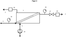
- FIG 2 shows, by way of example, a schematic representation of the implementation of the diafiltration process according to the invention using a crossflow diafiltration unit which is designed as a diafiltration cassette (1).
- the feed liquid (5) is fed to the inlet for the feed liquid via a pump (14).
- the pressure of the diafiltration medium (3) or the retentate (7) is measured by a pressure gauge (16).
- the respective composition of the retentate (7) and the permeate (2) is monitored by a measuring device, for example a conductometer (19).
- the volume flow of the retentate (7) is controlled by a throttle valve (17).
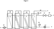
- FIG. 3 shows, by way of example, a schematic representation of the implementation of the diafiltration process according to the invention, with three diafiltration cassettes (1) connected in series. This is preceded by a step of separating a liquid into a pre-retentate and a pre-permeate using a conventional crossflow filtration cassette (11).
- the feed liquid (5) is supplied via a pump (14).
- the diafiltration medium (3) is supplied to the three diafiltration cassettes (1) via a pump (12).
- the pre-retentate from the respective upstream filtration unit is supplied via channel (10) to the respective downstream filtration unit as feed liquid.
- the pressure of the diafiltration medium (3) or the retentate (7) is measured by a manometer (16).
- the composition of the retentate (7) is monitored by a measuring device, for example a conductometer (19).
- the volume flow of the retentate (7) is controlled by a throttle valve (17).
- the permeate (2) from all modules (11, 1) is discharged via the collecting line (20).
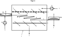
- FIG 4 shows, by way of example, a schematic representation of the implementation of the diafiltration method according to the invention and a crossflow diafiltration unit according to the present invention, wherein the feed liquid/retentate (5) is/are oscillated in the retentate gap.
- the feed liquid (5) is introduced into a reservoir (30a) and subsequently into the retentate gap via a pump (14).
- the feed liquid/retentate (5) then passes through a second device for generating oscillation or a second reservoir (30b).
- the diafiltration medium (3) is introduced into the diafiltration gap via a pump (12).
- the crossflow diafiltration unit shown has two devices for generating oscillation, wherein the first device comprises a first reservoir (30a) and the second device comprises a different second reservoir (30b).
- Reservoir (30a) is fluidically connected to the inlet for the feed liquid (5).
- Reservoir (30b) is fluidically connected to the outlet for the retentate (7).
- Each reservoir is separated into two halves by an elastic and fluid-impermeable membrane.
- the first half of the first reservoir (30a) (in Figure 4 not hatched) is connected to a pressure source via a valve control.
- the second half of the first reservoir (30a) (in Figure 4 hatched) is fluidically connected to the inlet for the feed liquid.
- the second reservoir (30b) is divided into two halves by an elastic and fluid-impermeable membrane.
- the first half of the second reservoir (30b) (in Figure 4 not hatched) is connected to a pressure source via a valve control.
- the second half of the second reservoir (30b) (in Figure 4
- the outlet for the retentate (shown hatched) is connected to the outlet for the retentate in a fluid-conducting manner.
- By controlling or regulating the pressure level of the compressed air pressurizing the first half of 30a and 30b in opposite directions with compressed air
- an oscillating movement of the feed liquid/retentate is generated in the retentate gap.
- Part of the retentate is continuously discharged in order to ensure continuous process control.
- Figure 5 shows, by way of example, various sections A to C of process diagrams for carrying out a method for producing biopharmaceuticals, wherein the processes each comprise the provision of at least one crossflow diafiltration unit (1) according to the invention.
- the dashed square brackets and the arrows in front and behind indicate that further process steps can be carried out upstream or downstream.
- the in Figure 5A The embodiment shown comprises a crossflow diafiltration unit (1) according to the invention, with a bioreactor (41) and a cell separation unit (42) being connected upstream.
- a chromatography unit/chromatography step (44) is connected downstream of the crossflow diafiltration unit (1).
- the flow of the product solution from the bioreactor (1) is illustrated by arrows.
- the in Figure 5B The embodiment shown comprises a crossflow diafiltration unit (1) according to the invention between two chromatography steps (44), ie the diafiltration is preceded by a chromatography step and followed by a chromatography step.
- the in Figure 5C The embodiment shown comprises a crossflow diafiltration unit (1) according to the invention before a final filtration step (45).
- the process steps shown can be expanded to include additional process steps or combined as desired.
- the crossflow filtration according to the invention is preferably used for filtration, diafiltration, concentration and/or changing the composition of a solution.
Landscapes
- Engineering & Computer Science (AREA)
- Water Supply & Treatment (AREA)
- Chemical & Material Sciences (AREA)
- Chemical Kinetics & Catalysis (AREA)
- Health & Medical Sciences (AREA)
- Life Sciences & Earth Sciences (AREA)
- Heart & Thoracic Surgery (AREA)
- Food Science & Technology (AREA)
- Polymers & Plastics (AREA)
- Vascular Medicine (AREA)
- Anesthesiology (AREA)
- Biomedical Technology (AREA)
- Hematology (AREA)
- Animal Behavior & Ethology (AREA)
- General Health & Medical Sciences (AREA)
- Public Health (AREA)
- Veterinary Medicine (AREA)
- Urology & Nephrology (AREA)
- Separation Using Semi-Permeable Membranes (AREA)
Abstract
Description
- Die vorliegende Erfindung betrifft eine Crossflow-Filtrationseinheit zur kontinuierlichen Diafiltration einer Speiseflüssigkeit zum Erhalten eines Retentats und eines Permeats, ein entsprechendes Verfahren zur Diafiltration und die Verwendung der Crossflow-Filtrationseinheit.
- Bei der Crossflow-Filtration, welche auch als Querstrom- oder Tangentialstromfiltration bezeichnet werden kann, überströmt eine zu filtrierende Speiseflüssigkeit ("Feed") tangential die Oberfläche eines Filtermaterials, welches üblicherweise eine Membran ist, und wird dabei in ein Retentat (Konzentrat) und ein Permeat (Filtrat) unterschiedlicher Zusammensetzungen aufgespalten.
- Das Retentat überströmt die Oberfläche des Filtermaterials und kann nach lediglich einmaligem Überströmen entnommen werden ("Single-Pass"-Betrieb), aber auch im Kreislauf wieder zurückgeführt werden, so dass es die Membranoberfläche wiederholt überströmt. Das Permeat durchströmt die Membran senkrecht zur Oberfläche und wird danach abgeführt. Zu gewinnende Zielsubstanzen können im Permeat (Permeatstoffe) und/oder im Retentat (Retentatstoffe) enthalten sein.
- Crossflow-Filtrationseinheiten werden häufig in Form von Filterkassetten eingesetzt, wie sie beispielsweise in der
DE-PS 34 41 249 beschrieben sind. Filterkassetten umfassen mehrere benachbarte Crossflow-Filtrationseinheiten (Filterzellen), die in der Regel aus wiederholten Anordnungen eines Retentatspalts für die zu filtrierende Speiseflüssigkeit bzw. das Retentat, einer flächigen Membranlage und einem Permeatsammelspalt bestehen. Der Permeatsammelspalt der vorstehenden Filterzelle wird durch eine weitere flächige Membranlage von dem Retentatspalt der nächsten Filterzelle abgegrenzt. Jeder Retentatspalt ist mit einem Einlass für die zu filtrierende Speiseflüssigkeit und mit einem Auslass für das Retentat fluidleitend (kommunizierend) verbunden und jeder Permeatsammelspalt ist mit einem Auslass für das Permeat fluidleitend verbunden. - Durch herkömmliche Filtration wird eine Speiseflüssigkeit in ein Retentat und ein Permeat aufgetrennt. In der Diafiltration wird diese Auftrennung mit einem Schritt des Zugebens eines Diafiltrationsmediums zu der Speiseflüssigkeit/dem Retentat kombiniert. Dadurch ist es beispielsweise möglich, eine gemeinsame Lösung von Zielsubstanz(en) und einer oder mehrerer weiterer Substanzen von den weiteren Substanzen zu befreien. Beispielsweise kann durch Diafiltration an einer Proteinlösung ein Pufferaustausch oder eine Entsalzung, gegebenenfalls kombiniert mit einer Aufkonzentration, erzielt werden.
- Es wird zwischen zwei grundlegenden Arten der Diafiltration unterschieden, der volumenvariablen Diafiltration (im Stand der Technik gelegentlich als "diskontinuierliche" Diafiltration bezeichnet) und der volumenkonstanten Diafiltration (im Stand der Technik gelegentlich als "kontinuierliche" Diafiltration bezeichnet).
- In der volumenvariablen Diafiltration wechseln sich Filtrationsschritte und Schritte des Zugebens eines Diafiltrationsmediums ab. Folglich schwankt im Verlauf dieser Verfahrensvariante das Volumen des Retentats, woher auch der Begriff der "diskontinuierlichen Diafiltration" rührt. In der volumenkonstanten Diafiltration wird das Volumen des Retentats dadurch konstant gehalten, dass sowohl die Filtration als auch die Zugabe des Diafiltrationsmediums kontinuierlich erfolgen. Allerdings erfolgt die Zugabe der Speiseflüssigkeit diskontinuierlich und in der Regel ausschließlich zu Beginn des Verfahrens. Daher sind sowohl die volumenvariable als auch die volumenkonstante Diafiltration diskontinuierliche Verfahren. Bei einem diskontinuierlichen Diafiltrationsverfahren muss ein festgelegtes Speiseflüssigkeitsvolumen komplett einem Verfahrensdurchlauf unterzogen werden, bevor ein neuer Verfahrensdurchlauf begonnen werden kann ("Batch"-Verfahren). Aus Gründen der Wirtschaftlichkeit und Effizienz sind kontinuierliche Verfahren, in denen laufend Stoffströme zu- und abgeführt werden können, diskontinuierlichen Verfahren vorzuziehen. Daher besteht der Bedarf an einem kontinuierlichen D iafi ltrationsverfahren.
- Der vorliegenden Erfindung liegt somit die Aufgabe zugrunde, eine Crossflow-Filtrationseinheit bereitzustellen, welche für die kontinuierliche Diafiltration geeignet ist.
- Diese Aufgabe wird durch die in den Ansprüchen gekennzeichneten Ausführungsformen gelöst.
- Insbesondere betrifft die vorliegende Erfindung eine Crossflow-Filtrationseinheit zur kontinuierlichen Diafiltration einer Speiseflüssigkeit zum Erhalten eines Retentats und eines Permeats, mindestens umfassend einen Diafiltrationspalt, ein flächiges erstes Filtermaterial, einen Retentatspalt, ein flächiges zweites Filtermaterial und einen Permeatsammelspalt, derart angeordnet, dass das flächige erste Filtermaterial den Diafiltrationspalt und den Retentatspalt voneinander abgrenzt und das flächige zweite Filtermaterial den Retentatspalt und den Permeatsammelspalt voneinander abgrenzt, wobei der Diafiltrationspalt fluidleitend mit mindestens einem Einlass für das Diafiltrationsmedium, der Retentatspalt fluidleitend mit mindestens einem Einlass für die Speiseflüssigkeit und mit mindestens einem Auslass für das Retentat und der Permeatsammelspalt fluidleitend mit mindestens einem Auslass für das Permeat verbunden ist, und wobei die Porengröße beziehungsweise die Molekulargewichtsausschlussgrenze des flächigen ersten Filtermaterials mindestens so groß wie die Porengröße beziehungsweise die Molekulargewichtsausschlussgrenze des flächigen zweiten Filtermaterials ist. Vorzugsweise ist die Porengröße beziehungsweise die Molekulargewichtsausschlussgrenze des flächigen ersten Filtermaterials größer als die Porengröße beziehungsweise die Molekulargewichtsausschlussgrenze des flächigen zweiten Filtermaterials.
- Vorzugsweise weist das flächige erste Filtermaterial eine Molekulargewichtsausschlussgrenze (molecular weight cut-off, MWCO) im Bereich von 30 kDa bis 1500 kDa auf. Das flächige zweite Filtermaterial weist vorzugsweise eine Molekulargewichtsausschlussgrenze im Bereich von 5 kDa bis 1500 kDa auf. Die Bestimmung der Molekulargewichtsausschlussgrenze kann gemäß US-Standard ASTM E1343-90 ("Standard test method for molecular weight cutoff evaluation of flat sheet ultrafiltration membranes") erfolgen.
- Das flächige erste Filtermaterial weist vorzugsweise eine Porengröße von 0,01 bis 50 µm, vorzugsweise 0,01 bis 0,5 µm auf. Das flächige zweite Filtermaterial weist vorzugsweise eine Porengröße von weniger als 0,01 µm auf. Die Bestimmung der Porengröße, welche auch als "größter Porendurchmesser" oder "dp" und im Englischen als "maximum pore size" bezeichnet wird, kann gemäß US-Standard ASTM F316-03 TEST METHOD A ("Standard test methods for pore size characteristics of membrane filters by bubble point and mean flow pore test") erfolgen.
- Grundlegende Verfahren zur Charakterisierung von Membranen sind in der Dissertationsschrift von Melanie Sossna "Strukturausbildung von Celluloseestermembranen", Universität Hannover 2006, Abschnitt 2.5 auf Seiten 10f, insbesondere in Tabelle 2-4, beschrieben.
- Gemäß dem Stand der Technik (diskontinuierliche Diafiltration) wird das Diafiltrationsmedium zwischen in Reihe geschalteten Crossflow-Filtrationseinheiten eingetragen oder die Speiseflüssigkeit mit Diafiltrationsmedium verdünnt, kombiniert mit vorgelagerter oder anschließender Konzentrierung durch Crossflow-Filtration. Durch die erfindungsgemäße Crossflow-Filtrationseinheit besteht jedoch die Möglichkeit, mittels geeigneter Druckbeaufschlagung eine bestimmte Menge an Diafiltrationsmedium für eine optimale Diafiltration in den Retentatspalt einzubringen. Beispielsweise kann erfindungsgemäß das Volumen des Diafiltrationsmediums das 0,1- bis 15-fache des Volumens der Speiseflüssigkeit betragen. Vorzugsweise wird das Diafiltrationsmedium derart in den Retentatspalt eingebracht, dass die gesamte zur Verfügung stehende Fläche des flächigen ersten Filtermaterials mit dem Diafiltrationsmedium bedeckt ist. Durch die erfindungsgemäße Crossflow-Filtrationseinheit kann ein im Vergleich zur diskontinuierlichen Diafiltration verbessertes Diafiltrationsergebnis erhalten werden. Außerdem führt die Erfindung zu einer Reduzierung der Prozesszeiten und des apparativen Aufwandes.
- In der kontinuierlichen Diafiltration werden sowohl Speiseflüssigkeit als auch Diafiltrationsmedium laufend zugegeben, so dass das Verfahren nicht unterbrochen werden muss. Dadurch ermöglicht die erfindungsgemäße Crossflow-Filtrationseinheit eine effiziente und wirtschaftliche Verfahrensführung.
- Mit der erfindungsgemäßen, verbesserten Crossflow-Filtrationseinheit können Fluide wie Flüssigkeiten, Emulsionen, Suspensionen, Getränke, wie Bier, Wein, Saft, Wasser, Milch und Molke, Bierwürze, Brauch- und Abwasser, Lösungen im Pharma-, Medizin-, Kosmetik-, Chemie-, Biotechnologie-, Gentechnik-, Umweltschutz- und Laborbereich als Speiseflüssigkeit eingesetzt und diafiltriert werden. Sie können zur Wertstoffgewinnung, Stofftrennung beispielweise von Makromolekülen und Biomolekülen, zur Entpyrogenisierung und Sterilisierung von Lösungen, zur Abtrennung von Schadstoffen aus den Fluiden, für die (Dia)filtration und Aufkonzentrierung biologischer Lösungen, für die Abtrennung von Mikroorganismen, wie Bakterien, Hefen, Viren und von Zellbestandteilen, für die Entsalzung von Proteinlösungen und anderen biologischen Medien verwendet werden.
- Besonders vorteilhaft kann die erfindungsgemäße Crossflow-Filtrationseinheit zur Filtration, Diafiltration, Aufkonzentrierung (Reduktion des Lösemittel- bzw. Wassergehaltes), und/oder Änderung der lonenzusammensetzung (z. B. Entsalzung oder Pufferaustausch) einer Lösung, vorzugsweise einer Proteinlösung, verwendet werden.
- Für die im Retentatspalt befindliche Flüssigkeit können die Begriffe Speiseflüssigkeit und Retentat gleichbedeutend verwendet werden.
- Der Begriff "flächig" zeigt an, dass das jeweilige Filtermaterial im Wesentlichen in einer einzigen Ebene liegt. Vorzugsweise liegen alle Filtermaterialien im Wesentlichen in Ebenen, die weitgehend parallel zueinander sind.
- Gemäß einer bevorzugten Ausführungsform der Erfindung ist das flächige erste Filtermaterial eine erste Filtrationsmembran. Das flächige zweite Filtermaterial ist vorzugsweise eine zweite Filtrationsmembran. Besonders bevorzugt ist das flächige erste Filtermaterial eine erste Filtrationsmembran und das flächige zweite Filtermaterial ist eine zweite Filtrationsmembran.
- Als erstes Filtermaterial ist insbesondere eine poröse Membran im Ultrafiltrations- und Mikrofiltrationsbereich geeignet. Als zweites Filtermaterial kann vorteilhaft eine Ultrafiltrationsmembran eingesetzt werden. Durch diese Ausgestaltung kann mittels geeigneter Druckbeaufschlagung eine bestimmte Menge an Diafiltrationsmedium für eine optimale Diafiltration in den Retentatspalt eingebracht werden. Bei Druckbeaufschlagung ist die gesamte zur Verfügung stehende Fläche des flächigen ersten Filtermaterials mit dem Diafiltrationsmedium bedeckt.
- Die Ultrafiltrationsmembranen sind durch Porengrößen von kleiner als 0,01 µm gekennzeichnet, beziehungsweise durch Molekulargewichtsausschlussgrenzen charakterisiert, die etwa im Molmassenbereich von 5 bis 1500 kDa liegen, während die Mikrofiltrationsmembranen Porengrößen im Bereich von 0,01 bis 50 µm, vorzugsweise 0,01 bis 0,5 µm, beziehungsweise Molekulargewichtsausschlussgrenzen von 30 bis 1500 kDa aufweisen. Die Filtrationsmembranen können beispielsweise aus Polyvinylidenfluorid, Cellulose und deren Derivaten, Polyethersulfon oder Polysulfon bestehen, wobei vernetztes Cellulosehydrat besonders bevorzugt ist.
- Vorzugsweise ist der Einlass für die Speiseflüssigkeit in einem ersten Randbereich der Crossflow-Filtrationseinheit angebracht und der Auslass für das Retentat in einem zweiten Randbereich der Crossflow-Filtrationseinheit, welcher dem ersten Randbereich gegenüberliegt, angebracht. Durch diese Anordnung wird eine weitgehend einheitliche Flussrichtung des Retentats vom Einlass für die Speiseflüssigkeit als Startpunkt zum Auslass für das Retentat als Endpunkt definiert. Die Flussrichtung des Retentats erfolgt dadurch weitgehend parallel zum Strömungsweg entlang des flächigen Filtermaterials, das heißt im Wesentlichen ohne Umlenkungen, wodurch ein stabiler und zuverlässiger Fluss des Retentats durch die Crossflow-Filtrationseinheit gewährleistet werden kann. Zudem können durch den weitgehend geradlinigen Strömungsverlauf ohne Umlenkungen, Schleifen oder ähnlichem der Druckabfall in der Filtrationseinheit sowie unerwünschte Einwirkungen nicht geradliniger Strömungen auf in der Speiseflüssigkeit enthaltene Zielsubstanzen minimiert werden. Aus den vorstehenden Gründen ist zudem bevorzugt, dass der Einlass für das Diafiltrationsmedium im ersten Randbereich der Crossflow-Filtrationseinheit angebracht ist. Es ist allerdings auch möglich, den Einlass für das Diafiltrationsmedium im zweiten Randbereich anzubringen, beziehungsweise im dritten und/oder vierten Randbereich.
- Gemäß einer bevorzugten Ausgestaltung der Erfindung ist der Auslass für das Permeat im zweiten Randbereich der Crossflow-Filtrationseinheit angebracht. Besonders bevorzugt ist sowohl im ersten als auch im zweiten Randbereich der Crossflow-Filtrationseinheit jeweils mindestens ein Auslass für das Permeat angebracht. In einer weiteren Ausgestaltung der Erfindung sind die Auslässe für das Permeat alternativ oder ergänzend im dritten und/oder vierten Randbereich der Crossflow-Filtrationseinheit angebracht. Der dritte Randbereich befindet sich bei einer Draufsicht auf die Crossflow-Filtrationseinheit von der Seite des Diafiltrationsspaltes auf der linken Seite der Flussrichtung. Der vierte Randbereich befindet sich entsprechend auf der rechten Seite und liegt somit dem dritten Randbereich gegenüber. Durch vorstehende Anordnung des Auslasses oder der Auslässe können eine besonders hohe Permeatleistung erzielt und konstruktionstechnische Vorteile erreicht werden.
- Vorzugsweise umfasst der erste Randbereich das äußere Drittel der Länge der Filtrationseinheit entgegen der Flussrichtung. Entsprechend umfasst der zweite Randbereich das äußere Drittel der Länge der Filtrationseinheit entlang der Flussrichtung. Entsprechendes gilt für die dritten und vierten Randbereiche. Es ist von Vorteil, die ersten bis vierten Randbereiche so klein wie möglich zu gestalten. Daher umfassen die Randbereiche besonders bevorzugt die jeweiligen äußeren 20%, noch mehr bevorzugt die jeweiligen äußeren 10% und am meisten bevorzugt die jeweiligen äußeren 3%.
- Grundsätzlich besteht hinsichtlich der Anbringung der Ein- und Auslässe keine besondere Einschränkung. Zum Beispiel können die Ein- und Auslässe so angebracht sein, dass die Speiseflüssigkeit bereits in Flussrichtung in den Retentatspalt eintritt und ihn in Flussrichtung verlässt. Entsprechend kann der Auslass für das Permeat so angebracht sein, dass das Permeat den Permeatsammelspalt in Flussrichtung verlässt und/oder der Einlass für das Diafiltrationsmedium kann so angebracht sein, dass es in Flussrichtung in den Diafiltrationsspalt eintritt. Vorzugsweise sind die Ein- und Auslässe jedoch so angebracht, dass das Diafiltrationsmedium senkrecht zur Flussrichtung in den Diafiltrationsspalt eintritt und die Speiseflüssigkeit zunächst senkrecht zur Flussrichtung in den Retentatspalt eintritt und diesen senkrecht zur Flussrichtung als Retentat verlässt. Eine derartige Anbringung der Ein- und Auslässe erleichtert die Anordnung einer Mehrzahl der erfindungsgemäßen Filtrationseinheiten zu einer Filterkassette.
- Vorzugsweise weist die Crossflow-Filtrationseinheit mehrere Einlässe für die Speiseflüssigkeit, mehrere Auslässe für das Retentat und mehrere Auslässe für das Permeat auf.
- In einer bevorzugten Ausgestaltung nimmt das freie Volumen des Diafiltrationsspaltes und/oder des Retentatspaltes (für das Diafiltrationsmedium/Retentat zur Verfügung stehender Raum, Tot- oder Leervolumen) in der Flussrichtung vom Einlass für die Speiseflüssigkeit zum Auslass für das Retentat ab. Durch das/die abnehmenden Volumen/Volumina und die Flächigkeit der Filtermaterialien weist die Crossflow-Filtrationseinheit einen niedrigen Druckverlust und einen im Wesentlichen umlenkungsfreien Strömungsweg des Diafiltrationsmediums und des Retentats auf. Dadurch ist es möglich, die Flächenleistung der Crossflow-Diafiltrationseinheit zu erhöhen und die Crossflow-Diafiltrationseinheit im "Single-Pass"-Betrieb zu betreiben (es findet nur ein einziger Durchgang des Retentats ohne Kreislaufführung statt).
- In einer weiteren bevorzugten Ausgestaltung der Erfindung wird die Abnahme des freien Volumens entlang der Flussrichtung dadurch realisiert, dass die Breite des Diafiltrationsspaltes und/oder die Breite des Retentatspaltes in Flussrichtung abnimmt. Die Breite verläuft entlang des flächigen ersten Filtermaterials und senkrecht zur Flussrichtung. Besonders bevorzugt nimmt die Breite der gesamten Crossflow-Filtrationseinheit in Flussrichtung ab. Vorzugsweise ist der Retentatspalt bzw. die Crossflow-Filtrationseinheit in einer Draufsicht entlang einer Normalen der Ebene, in der das flächige erste Filtermaterial liegt, trapezförmig. Die Trapez-Grundform des Diafiltrationsspaltes und/oder des Retentatspaltes bzw. der Crossflow-Filtrationseinheit kann ungleichschenklig, beispielsweise rechtwinklig, sein und ist vorzugsweise gleichschenklig.
- Gemäß einer Ausführungsform kann die Höhe des Diafiltrationsspaltes und/oder des Retentatspaltes bzw. der Crossflow-Filtrationseinheit in Flussrichtung abnehmen. Beispielsweise können der Diafiltrationsspalt und/oder der Retentatspalt keilförmig ausgestaltet sein. Die Höhe des Diafiltrationsspaltes und/oder des Retentatspaltes bzw. der Crossflow-Filtrationseinheit verläuft senkrecht zum flächigen ersten Filtermaterial und senkrecht zur Flussrichtung.
- Hinsichtlich der Breite, Länge und Höhe der Crossflow-Filtrationseinheit besteht keine besondere Einschränkung. Die Länge verläuft parallel zur Flussrichtung und entlang des flächigen ersten Filtermaterials. Vorzugsweise weist die Crossflow-Filtrationseinheit eine Länge von mindestens 50 mm, bevorzugt mindestens 150 mm, besonders bevorzugt 500 mm, insbesondere bevorzugt 750 mm oder mehr, auf. Eine derartige Länge kann beispielsweise durch Hintereinanderschalten mehrerer, beispielsweise mindestens 2, mindestens 3 oder mindestens 4, Crossflow-Filtrationseinheiten erzielt werden. Durch eine höhere Länge kann eine besonders hohe Effizienz erzielt werden.
- In einer bevorzugten Ausführungsform der Erfindung ändert sich das freie Volumen des Permeatsammelspaltes in der Flussrichtung. Besonders bevorzugt nimmt das freie Volumen des Permeatsammelspaltes in der Flussrichtung ab. Dadurch können beispielsweise die äußeren Dimensionen der Filtrationskassette beibehalten werden.
- Die Erläuterungen zur Ausgestaltung des Retentatspaltes gelten entsprechend für den Permeatsammelspalt und umgekehrt.
- "In Flussrichtung abnehmendes freies Volumen" bedeutet, dass eine Querschnittsfläche A1, welche von dem Diafiltrationsmedium beziehungsweise dem Retentat durchströmt werden kann und die in einer Ebene liegt, welche eine parallel zur Flussrichtung verlaufende Normale aufweist, und eine entsprechende Querschnittsfläche A2, die parallel zu A1 ist und weiter vom Einlass für das Diafiltrationsmedium beziehungsweise die Speiseflüssigkeit entfernt ist als A1, wobei der von dem Diafiltrationsmedium beziehungsweise dem Retentat durchströmbare Flächeninhalt A1 größer ist als A2, existieren und keine entsprechend definierten Ebenen A1' und A2' existieren, für die der Flächeninhalt von A1' kleiner als der von A2' ist.
- Die Abnahme des freien Volumens kann stetig (für alle A1 und A2 gilt A1 ≥ A2) oder kontinuierlich (für alle A1 und A2 gilt A1 > A2) sein. Es ist auch möglich, dass die Volumenabnahme diskontinuierlich ist, das heißt, dass entlang der Flussrichtung mindestens ein unstetiger Abfall oder Sprung in der Querschnittsfläche auftritt.
- Die Änderung des freien Volumens des Retentatspaltes in Flussrichtung liegt vorzugsweise im Bereich von 20 zu 1 bis 1,2 zu 1, bevorzugt bei 10 zu 1, abhängig von der Filtrationsaufgabe. Dabei wird unter der "Änderung des freien Volumens des Retentatspaltes in Flussrichtung" das Verhältnis der Querschnittsfläche A1 am Einlass für die Speiseflüssigkeit zur Querschnittsfläche A2 am Auslass für das Retentat verstanden.
- In einer Ausgestaltung der Erfindung nimmt/nehmen die Dicke des Diafiltrationsspaltes und/oder die Dicke des Retentatspaltes und gegebenenfalls die Dicke des Permeatsammelspaltes in Flussrichtung ab.
- Der Diafiltrationsspalt, der Retentatspalt und der Permeatsammelspalt werden üblicherweise durch Abstandshalter für die entsprechenden Medien offengehalten. In einer bevorzugten Ausgestaltung der Erfindung ist/sind im Diafiltrationsspalt und/oder im Retentatspalt der Crossflow-Filtrationseinheit ein flächiger Abstandshalter angebracht, derart, dass das freie Volumen des Retentatspaltes in Flussrichtung abnimmt.
- Geeignete Abstandshalter für Crossflow-Filtrationseinheiten sind im Stand der Technik bekannt und können im Diafiltrationsspalt, Retentatspalt und/oder Permeatsammelspalt der erfindungsgemäßen Crossflow-Filtrationseinheit verwendet werden. Vorzugsweise sind die Abstandshalter erfindungsgemäß so modifiziert, dass ihr Volumen in Flussrichtung zunimmt, um eine Volumenabnahme des für das Diafiltrationsmedium bzw. das Retentat zur Verfügung stehenden freien Volumens zu erzielen. Bevorzugte Abstandshalter können textile Materialien aus organischen oder nicht-organischen Werkstoffen sein, wie Gewebe, Gewirke, Vliese oder extrudierte Netze.
- Vorteilhaft kann der Abstandshalter eine nicht ebene Platte sein. Die nicht ebene Platte kann eine Platte sein, die zumindest eine nicht ebene Hauptoberfläche aufweist. Die Hauptoberflächen einer Platte sind die sich gegenüberstehenden Oberflächen mit dem größten Flächeninhalt. Die zumindest eine nicht ebene Hauptoberfläche kann Unebenheiten in Form einer gewellten oder gezackten Oberfläche aufweisen. Daneben kann die unebene Oberfläche vorstehende Elemente wie Kegel(stümpfe), Pyramiden(stümpfe), Noppen oder andere geometrische Figuren aufweisen. Die nicht ebene Platte kann auch ähnlich einem Wellblech in gewellter oder gezackter Form vorliegen, wobei sich die Wellen oder Zacken vorzugsweise parallel zur Flussrichtung erstrecken. Geeignete Materialien für die nicht ebene Platte sind die gleichen wie nachstehend für Abstandshalter in Form einer offenmaschigen Matrix aufgeführt.
- Gemäß einer bevorzugten Ausführungsform besteht der Abstandshalter aus einer offenmaschigen Matrix oder aus einem extrudierten Netz. Derartige Abstandshalter sind im Stand der Technik bekannt und wurden beispielsweise in der Veröffentlichung der deutschen Patentanmeldung
DE 100 22 259 A1 beschrieben. Wie bereits vorstehend erwähnt, sind die Abstandshalter erfindungsgemäß vorzugsweise so abgewandelt, dass ihr Volumen in Flussrichtung zunimmt, um eine Volumenabnahme des für das Diafiltrationsmedium bzw. das Retentat zur Verfügung stehenden freien Volumens zu erzielen. Grundsätzlich können in der erfindungsgemäßen Crossflow-Filtrationseinheit auch gewöhnliche Abstandshalter verbaut werden, beispielsweise im Permeatsammelspalt und/oder im Diafiltrationsspalt oder in allen Spalten der Filtrationseinheit mit in Flussrichtung abnehmender Breite. Eine abnehmende Breite kann, wie vorstehend beschrieben, beispielsweise durch eine trapezförmige Ausgestaltung der Spalten beziehungsweise der Crossflow-Filtrationseinheit erzielt werden. - In einer Ausgestaltung kann die Maschenweite der offenmaschigen Matrix beziehungsweise des extrudierten Netzes in Flussrichtung abnehmen, um eine Abnahme des freien Volumens entlang der Flussrichtung zu erzielen. Beispielsweise beträgt die Maschenzahl am Einlass für das Diafiltrationsmedium beziehungsweise am Einlass für die Speiseflüssigkeit 5/cm bis 15/cm, in der Mitte zwischen dem Einlass für das Diafiltrationsmedium beziehungsweise dem Einlass für die Speiseflüssigkeit und dem Auslass für das Retentat 10/cm bis 30/cm und am Auslass für das Retentat 20/cm bis 40/cm.
- Alternativ oder ergänzend dazu kann die offenmaschige Matrix beziehungsweise das extrudierte Netz aus sich kreuzenden Längs- und Querfäden aufgebaut sein und die Anzahl und/oder Dicke der Längs- und/oder Querfäden in Flussrichtung zunehmen. Die offenmaschige Matrix besteht vorzugsweise aus einem organischen Polymer wie beispielsweise Polypropylen, Polyethylen, Polyester, Polyvinylchlorid oder Polyvinylidenfluorid oder Blends daraus. Ferner ist möglich, dass die offenmaschige Matrix aus Fasern verschiedenartiger Polymere aufgebaut ist.
- In einer weiteren bevorzugten Ausgestaltung der Erfindung sind im Retentatspalt mehrere Lagen textiler Materialien derart übereinander angeordnet, dass das freie Kanalvolumen in Flussrichtung abnimmt. Dies kann beispielsweise dadurch erreicht werden, dass die übereinander angeordneten Lagen in Flussrichtung versetzt beginnen. Die übereinander angeordneten Lagen erstrecken sich vorzugsweise bis zum zweiten Randbereich. Dadurch wird im Retentatspalt in Flussrichtung ein zunehmendes Volumen von den textilen Materialien in Anspruch genommen, sodass das freie Volumen in Flussrichtung abnimmt. Die textilen Materialien, wie Gewebe, Gewirke, Vliese oder extrudierte Netze, können aus organischen oder nicht-organischen Werkstoffen bestehen.
- Die hier dargestellten Ausgestaltungen zur Realisierung der Abnahme des freien Volumens des Diafiltrationsspaltes bzw. Retentatspaltes sind beliebig miteinander kombinierbar.
- Erfindungsgemäß wird der Retentatspalt von einem flächigen ersten Filtermaterial und einem flächigen zweiten Filtermaterial begrenzt. Der Diafiltrationsspalt wird durch mindestens ein flächiges erstes Filtermaterial begrenzt. Der Permeatsammelspalt wird durch mindestens ein flächiges zweites Filtermaterial begrenzt. Einem Retentatspalt ist ein Diafiltrationsspalt und ein Permeatsammelspalt benachbart. Eine bevorzugte erfindungsgemäße Crossflow-Filtrationseinheit besteht aus einer Mehrzahl übereinandergestapelter Anordnungen von Diafiltrationspalt, flächigem erstem Filtermaterial, Retentatspalt, flächigem zweitem Filtermaterial, Permeatsammelspalt, flächigem zweitem Filtermaterial, Retentatspalt und flächigem erstem Filtermaterial, vorzugsweise abgeschlossen von einem weiteren Diafiltrationsspalt, sodass die gestapelten Anordnungen zu einer Filterkassette zusammengefasst sind. Geeignete Ausgestaltungen für Filterkassetten sind im Stand der Technik bekannt. Vorzugsweise ist jeder Diafiltrationsspalt dieser Anordnungen an beiden Seiten durch jeweils ein Filtermaterial, welches dem ersten Filtermaterial entspricht, von zwei Retentatspalten abgegrenzt. Entsprechend ist vorzugsweise jeder Permeatsammelspalt dieser Anordnungen an beiden Seiten durch jeweils ein Filtermaterial, welches dem zweiten Filtermaterial entspricht, von zwei Retentatspalten abgegrenzt. Die ersten Filtermaterialien und zweiten Filtermaterialien können jeweils voneinander verschieden sein. Das heißt, es können grundsätzlich verschiedenartige erste Filtermaterialien und verschiedenartige zweite Filtermaterialien verwendet werden. Vorzugsweise werden gleichartige erste Filtermaterialien und/oder gleichartige zweite Filtermaterialien verwendet.
- Gemäß einer bevorzugten Ausführungsform weisen die flächigen ersten und zweiten Filtermaterialien unabhängig voneinander eine jeweils weitgehend einheitliche Dicke von vorzugsweise 50 µm bis 10000 µm, insbesondere bevorzugt 150 µm bis 1000 µm, auf. Sofern die flächige Begrenzung des Diafiltrationsspaltes durch das flächige erste Filtermaterial und die weitere flächige Begrenzung des Diafiltrationsspaltes und/oder die flächigen Begrenzungen des Retentatspaltes durch das erste und zweite Filtermaterial nicht parallel zueinander verlaufen, kann das freie Volumen des Diafiltrationsspaltes und/oder des Retentatspaltes keilförmig ausgestaltet werden, so dass in Flussrichtung das freie Volumen abnimmt. Besonders bevorzugt sind der Diafiltrationsspalt, der Retentatspalt und der Permeatsammelspalt beidseitig von weitgehend parallelen Flächen begrenzt.
- Die Form der Crossflow-Filtrationseinheit unterliegt keiner besonderen Einschränkung. Die Crossflow-Filtrationseinheit kann beispielsweise quaderförmig oder zylinderförmig sein.
- In einem weiteren Aspekt betrifft die vorliegende Erfindung ein Verfahren zur Diafiltration einer Speiseflüssigkeit zum Erhalten eines Retentats und eines Permeats, umfassend die Schritte
- (A) Bereitstellen einer erfindungsgemäßem Crossflow-Filtrationseinheit;
- (B) Zuführen eines Diafiltrationsmediums in den Einlass für das Diafiltrationsmedium;
- (C) Zuführen der Speiseflüssigkeit in den Einlass für die Speiseflüssigkeit;
- (D) Abführen des Retentats aus dem Auslass für das Retentat; und
- (E) Abführen des Permeats aus dem Auslass für das Permeat.
- Die Erläuterungen in Bezug auf die Crossflow-Filtrationseinheit und das Diafiltrationsverfahren sind wechselseitig aufeinander anwendbar.
- In Schritt (A) wird bevorzugt die vorstehend beschriebene Crossflow-Filtrationseinheit bereitgestellt, welche eine Mehrzahl übereinandergestapelter Anordnungen von Diafiltrationsspalt, flächigem ersten Filtermaterial, Retentatspalt, flächigem zweiten Filtermaterial, Permeatsammelspalt, flächigem zweiten Filtermaterial, Retentatspalt und flächigem ersten Filtermaterial aufweist, sodass die gestapelten Anordnungen zu einer Filterkassette zusammengefasst sind.
- Das verwendete Diafiltrationsmedium unterliegt keiner besonderen Einschränkung. Geeignet ist grundsätzlich jedes Fluid, wobei Wasser und wässrige Salzlösungen bevorzugt sind. Besonders bevorzugt ist als Diafiltrationsmedium eine wässrige Pufferlösung.
- Vorzugsweise beträgt der Volumenstrom des zugeführten Diafiltrationsmediums das 0,1- bis 15-fache des Volumenstroms der zugeführten Speiseflüssigkeit. Der Volumenstrom des abgeführten Retentats beträgt vorzugsweise das 0,05- bis 10-fache des Volumenstroms der zugeführten Speiseflüssigkeit.
- In einer bevorzugten Ausgestaltung des Verfahrens wird das Diafiltrationsmedium mit einem Druck von 0,1 bis 4 bar zugeführt. Besonders bevorzugt wird das Diafiltrationsmedium mit einem Druck zugeführt, der größer ist als der Retentatausgangsdruck.
- Vorzugsweise wird das erfindungsgemäße Verfahren kontinuierlich betrieben, das heißt unter konstanter/kontinuierlicher Zugabe des Diafiltrationsmediums und der Speiseflüssigkeit, wodurch ein besonders effizientes und wirtschaftliches Filtrationsverfahren bereitgestellt werden kann. Erfindungsgemäß wird unter "kontinuierlicher Diafiltration" ein Diafiltrationsverfahren verstanden, in dem sowohl das Diafiltrationsmedium als auch die Speiseflüssigkeit kontinuierlich zugegeben werden.
- In einer bevorzugten Ausgestaltung des Verfahrens werden in Schritt (A) mehrere erfindungsgemäße und voneinander unabhängige Crossflow-Filtrationseinheiten bereitgestellt und so in Reihe geschaltet, dass der Auslass für das Retentat der jeweiligen vorgeschalteten Crossflow-Filtrationseinheit fluidleitend mit dem Einlass für die Speiseflüssigkeit einer nachgeschalteten Crossflow-Filtrationseinheit verbunden ist. In dieser Ausgestaltung wird zudem in Schritt (C) die Speiseflüssigkeit in den Einlass für die Speiseflüssigkeit derjenigen Crossflow-Filtrationseinheit, welcher keine andere Crossflow-Filtrationseinheit vorgeschaltet ist (erste Crossflow-Filtrationseinheit), zugeführt und in Schritt (D) das Retentat aus dem Auslass für das Retentat derjenigen Crossflow-Filtrationseinheit, welcher keine andere Crossflow-Filtrationseinheit nachgeschaltet ist (letzte Crossflow-Filtrationseinheit), abgeführt. Somit durchläuft das Retentat/die Speiseflüssigkeit die in Reihe geschalteten Crossflow-Filtrationseinheiten von der ersten bis zur letzten. Vorzugsweise werden 2 bis 10, besonders bevorzugt 2 bis 5 Crossflow-Filtrationseinheiten in Reihe geschaltet. Das Diafiltrationsmedium wird in dieser Ausgestaltung jeder der in Reihe geschalteten Crossflow-Filtrationseinheiten getrennt zugeführt. Es ist zwar möglich, verschiedenartige Diafiltrationsmedien zu verwenden, wobei bevorzugt ist, jeder der Crossflow-Filtrationseinheiten das gleiche Diafiltrationsmedium zuzuführen. Vorzugsweise liegt jede der in Reihe geschalteten Crossflow-Filtrationseinheiten, wie vorstehend beschrieben, in Form einer Filterkassette vor.
- In einer bevorzugten Ausgestaltung des Verfahrens werden in Schritt (A) mehrere erfindungsgemäße und voneinander unabhängige Crossflow-Filtrationseinheiten bereitgestellt und parallelgeschaltet. Parallel- und Reihenschaltung können miteinander kombiniert werden.
- In einer weiteren bevorzugten Ausführungsform des Verfahrens wird das in Schritt (D) abgeführte Retentat zumindest teilweise in den Einlass für die Speiseflüssigkeit zurückgeführt. Durch einen Kreislaufprozess kann, sofern ein einziger Durchlauf durch die Crossflow-Filtrationseinheit nicht ausreicht, ein verbessertes Ergebnis des Verfahrens erzielt werden. Die Zugabe der Diafiltrationsflüssigkeit und die Entnahme des Permeats erfolgen hierbei ohne Rückführung. Sind mehrere Crossflow-Filtrationseinheiten in Serie geschaltet, kann grundsätzlich jeder Retentatstrom zu jedem Einlass für die Speiseflüssigkeit zurückgeführt werden. Vorzugsweise wird hierbei das Retentat jeder einzelnen Crossflow-Filtrationseinheit zum Einlass für die Speiseflüssigkeit derselben Crossflow-Filtrationseinheit zurückgeführt.
- Gemäß einer weiteren bevorzugten Ausführungsform des erfindungsgemäßen Verfahrens wird/werden die Speiseflüssigkeit beziehungsweise das Retentat im Retentatspalt in Oszillation versetzt. Dadurch wird die Strömungsbewegung im Retentatspalt durch eine Oszillation (Schwingung) überlagert. Bewerkstelligt werden kann dies durch mindestens eine Vorrichtung zur Erzeugung von Oszillation, die am Speiseflüssigkeitseinlass und/oder am Retentatauslass angebracht sein kann. Eine derartige Vorrichtung zur Erzeugung von Oszillation bewegt das Retentat im Retentatspalt hin und her, das heißt, das Retentat wird in eine zum flächigen ersten Filtermaterial weitgehend parallel verlaufende oszillierende Bewegung versetzt. Vorzugsweise wird die Oszillation von einer Vorrichtung zur Erzeugung von Oszillation, die am Speiseflüssigkeitseinlass angebracht ist, sowie einer weiteren Vorrichtung zur Erzeugung von Oszillation, die am Retentatauslass angebracht ist, erzeugt. Eine erfindungsgemäß geeignete Vorrichtung zur Erzeugung von Oszillation ist beispielsweise eine Kolbenpumpe. Bevorzugt umfasst eine Vorrichtung zur Erzeugung von Oszillation ein Reservoir, das durch eine elastische Membran in zwei Hälften unterteilt ist, und gegebenenfalls eine Druckquelle. Das Reservoir ist ein Reservoir (Speicher) für die Speiseflüssigkeit beziehungsweise das Retentat. Die erste Hälfte des Reservoirs ist über eine Ventilsteuerung mit einer Druckquelle, wie z. B. einer Druckluftquelle oder einer Pumpe, verbunden. Die zweite Hälfte des Reservoirs ist fluidleitend mit dem Speiseflüssigkeitseinlass bzw. dem Retentatauslass der Filtrationsvorrichtung verbunden. In der zweiten Hälfte befindet sich außerdem vorzugsweise ein Entleerungs- bzw. Entlüftungsventil. Durch gegenläufiges (alternierendes bzw. abwechselndes) Beaufschlagen jeweils einer der ersten Hälften der beiden Reservoire mit Druck (beispielsweise mit Druckluft) kann so die Retentatströmung hin- und herbewegt (in Oszillation bzw. Schwingung versetzt) werden. Die vorstehend beschriebenen Reservoire können sowohl separater Anlagenteil (nicht Teil der Crossflow-Filtrationseinheit) sein, als auch als Teil der Crossflow-Filtrationseinheit in deren Gehäuse integriert sein.
- Vorzugsweise weist die erfindungsgemäße Crossflow-Filtrationseinheit mindestens eine (vorzugsweise zwei) Vorrichtung(en) zur Erzeugung einer Oszillation der Speiseflüssigkeit beziehungsweise des Retentats im Retentatspalt auf. Es ist erfindungsgemäß bevorzugt, dass eine Vorrichtung zur Erzeugung von Oszillation ein Reservoir mit einer Druckquelle aufweist. Besonders bevorzugt umfasst die erfindungsgemäße Crossflow-Filtrationseinheit ein erstes Reservoir, gegebenenfalls mit einer ersten Druckquelle, und ein zweites Reservoir, gegebenenfalls mit einer zweiten Druckquelle, wobei das erste Reservoir fluidleitend mit dem Einlass für die Speiseflüssigkeit verbunden ist und das zweite Reservoir fluidleitend mit dem Auslass für das Retentat verbunden ist, mit der Maßgabe, dass zumindest eine der ersten und zweiten Druckquellen vorhanden ist. Vorzugsweise weisen sowohl das erste als auch das zweite Reservoir jeweils eine Druckquelle auf. Jedes der Reservoire ist vorzugsweise durch eine elastische und fluidundurchlässige (gas- und flüssigkeitsundurchlässige) Membran in zwei Hälften unterteilt, wobei die erste Hälfte mit einer Druckquelle verbunden ist. Die zweite Hälfte des ersten Reservoirs ist vorzugsweise fluidleitend mit dem Einlass für die Speiseflüssigkeit verbunden. Die zweite Hälfte des zweiten Reservoirs ist vorzugsweise fluidleitend mit dem Auslass für das Rententat verbunden.
- Gemäß einer bevorzugten Ausführungsform umfasst das erfindungsgemäße Verfahren weiter den Schritt (C0) der Auftrennung einer Vorspeiseflüssigkeit in ein Vorretentat und ein Vorpermeat. Durch diesen vorgeschalteten Schritt kann eine Flüssigkeit zunächst beispielsweise durch Filtration oder Diafiltration aufkonzentriert und/oder von Verunreinigungen (teil)befreit werden, um dann einer nachfolgenden Diafiltration unter Verwendung der erfindungsgemäßen Crossflow-Filtrationseinheit unterzogen zu werden. Sofern Schritt (C0) ein Filtrationsschritt oder Diafiltrationsschritt ist, können grundsätzlich sowohl das Vorretentat als auch das Vorpermeat als Speiseflüssigkeit verwendet werden, bevorzugt wird jedoch das Vorretentat aus Schritt (C0) verwendet.
- Schritt (C0) wird vorteilhaft unter Verwendung einer Crossflow-Filtrationseinheit (CO-Einheit) zur Trennung einer Vorspeiseflüssigkeit in ein Vorretentat und ein Vorpermeat durchgeführt. Derartige Crossflow-Filtrationseinheiten sind im Stand der Technik bekannt. Die CO-Einheit kann dabei, wie vorstehend für die Reihenschaltung der erfindungsgemäßen Crossflow-Filtrationseinheiten beschrieben, der ersten Crossflow-Filtrationseinheit vorgeschaltet werden.
- Besonders vorteilhaft ist als CO-Einheit eine Crossflow-Filtrationseinheit, umfassend einen Vorretentatspalt, ein flächiges Filtermaterial und einen Vorpermeatsammelspalt, derart angeordnet, dass das flächige Filtermaterial den Vorretentatspalt und den Vorpermeatsammelspalt voneinander abgrenzt, wobei der Vorretentatspalt fluidleitend mit mindestens einem Einlass für die Vorspeiseflüssigkeit und mit mindestens einem Auslass für das Vorretentat verbunden ist und der Vorpermeatsammelspalt fluidleitend mit mindestens einem Auslass für das Vorpermeat verbunden ist, der Einlass für die Vorspeiseflüssigkeit in einem ersten Randbereich der Crossflow-Filtrationseinheit angebracht ist und der Auslass für das Vorretentat in einem zweiten Randbereich der Crossflow-Filtrationseinheit, welcher dem ersten Randbereich gegenüberliegt, angebracht ist, und vorzugsweise das freie Volumen des Vorretentatspaltes in der Flussrichtung vom Einlass für die Vorspeiseflüssigkeit zum Auslass für das Vorretentat abnimmt. Durch die Abnahme des freien Volumens in Flussrichtung kann eine CO-Einheit mit geringem Druckverlust und hoher Flächenausnutzung bereitgestellt werden.
- Für die Ausgestaltung der CO-Einheit und insbesondere des Vorretentatspaltes und des Vorpermeatsammelspaltes gelten die Ausführungen in Bezug auf die erfindungsgemäße Crossflow-Filtrationseinheit zur Diafiltration und insbesondere die Ausführungen in Bezug auf deren Retentatspalt und Permeatsammelspalt entsprechend. Das flächige Filtermaterial der CO-Einheit kann eine Mikrofiltrationsmembran und vorzugsweise eine Ultrafiltrationsmembran sein. Wie auch die erfindungsgemäße Crossflow-Filtrationseinheit, kann die CO-Einheit zu einer Filterkassette ausgebaut sein.
- Das erfindungsgemäße Verfahren wird vorzugsweise unter den folgenden Bedingungen betrieben:
- PDF ≥ PRetentat;
- x = VDF/VFeed, vorzugsweise ist x ≥ 1, besonders bevorzugt 3 bis 10; und
- k = VFeed/VRetentat, vorzugsweise ist k ≥ 1;
- PDF der Druck ist, mit dem das Diafiltrationsmedium zugegeben wird,
- PRetentat der Retentatausgangdruck ist, d. h. der Druck mit dem das Retentat die Filtrationsvorrichtung verlässt,
- VRetentat der Volumenstrom des Retentats ist,
- VDF der Volumenstrom des Diafiltrationsmediums ist,
- VFeed der Volumenstrom der Speiseflüssigkeit ist,
- x das sogenannte DF-Verhältnis ist und
- k der sogenannte Konzentrationsfaktor ist.
- Das erfindungsgemäße Verfahren eignet sich besonders für die Filtration, Diafiltration, Aufkonzentrierung und/oder Änderung der lonenzusammensetzung einer Proteinlösung oder Kombinationen davon.
- Das erfindungsgemäße Verfahren kann Bestandteil eines umfassenderen Verfahrensablaufes sein. Beispielsweise kann das Diafiltrationsverfahren einer Vorbehandlung nachgeschaltet und/oder einer Nachbehandlung vorgeschaltet sein. Beispielhaft für geeignete Vor- beziehungsweise Nachbehandlungen sind Umsetzen von Edukten zu Produkten auf biologischem oder chemischem Wege, thermische und mechanische Trennverfahren und chemische Analyseverfahren.
- Die vorliegende Erfindung betrifft in einem weiteren Aspekt eine Vorrichtung zur Durchführung eines chemischen oder biologischen Verfahrens, welche die vorstehend beschriebene Crossflow-Diafiltrationseinheit umfasst. Eine derartige Vorrichtung kann beispielsweise einen Bioreaktor, eine Einheit zur Zellabtrennung, eine Einheit zur Diafiltration mit der erfindungsgemäßen Crossflow-Diafiltrationseinheit und eine Einheit zur Chromatographie umfassen. Geeignete chemische und biologische Verfahren sind beispielsweise die Herstellung von Impfstoffen oder Biopharmazeutika.
- Darüber hinaus betrifft die vorliegende Erfindung die Verwendung der Crossflow-Filtrationseinheit für die kontinuierliche Diafiltration innerhalb eines chemischen oder biologischen Verfahrens, wobei dem Schritt der kontinuierlichen Diafiltration mindestens ein Aufbereitungsschritt für die Speiseflüssigkeit vorgelagert und/oder mindestens ein Nachbereitungsschritt für das Retentat nachgelagert ist. Geeignete Auf- bzw. Nachbereitungsschritte sind beispielsweise Umsetzen in einem Bioreaktor, gegebenenfalls gefolgt von Zellabtrennung, Chromatographie, Filtration, Aufkonzentrierung und Verdünnung (siehe
Figur 4 ). - Die vorliegende Erfindung wird durch die folgenden Beispiele erläutert, ohne darauf beschränkt zu sein.
- Eine Lösung von Albumin und NaCl (5,2 Gew.% Albumin in 0,9 Gew.% wässriger NaCl-Lösung) wurde einer Diafiltration unterzogen. Die Bestimmung der Albuminkonzentration erfolgte photometrisch bei einer Wellenlänge des Lichtes von 280 nm. Die Leitfähigkeit der Ausgangslösung betrug 14 mS. Als Diafiltrationsmedium wurde demineralisiertes Wasser verwendet.
- Die Diafiltrationseinheit war als Filterkassette ausgebildet, wobei 13 Anordnungen von Diafiltrationspalt, flächigem ersten Filtermaterial, Retentatspalt, flächigem zweiten Filtermaterial, Permeatsammelspalt, flächigem zweiten Filtermaterial, Retentatspalt und flächigem ersten Filtermaterial übereinandergestapelt waren und von einem weiteren Diafiltrationsspalt ergänzt wurden. Als flächiges zweites Filtermaterial wurde eine Hydrosart® Membran des Typs 10 kDa der Sartorius Stedim Biotech GmbH verwendet. Als flächiges erstes Filtermaterial wurde eine Polyethersulfonmembran des Typs 30 kDa der Sartorius Stedim Biotech GmbH verwendet. Das DF-Verhältnis (Volumen Diafiltrationsmedium / Volumen Speiseflüssigkeit) betrug etwa 5,5 : 1.
- Während der Versuchsdauer wurden die Einstellungen der Pumpen und Ventile nicht nachgeregelt. Die Diafiltrationseinheit arbeitete mit stabilen Leistungen. Die geringe Leitfähigkeit des Retentats von 2,2 mS zeigt an, dass eine hervorragende Diafiltrationsleistung erzielt wurde.
- Das Ergebnis des vorstehenden Beispiels ist in der folgenden Tabelle 1 dargestellt.
Tabelle 1 Zeit (min) PFeed (bar) PRetentat (bar) PDF (bar) VFeed (ml/min) VRetentat (ml/min) VPermeat ml/min cProtein (Gew.%) x (Vol/Vol) LFPermeat (mS) LFRetentat (mS) T (°C) 0 (Start) 2,42 0,77 1,8 14,6 12,8 80,8 5,6 5,5 : 1 2,5 mS 2,25 mS ca. 20°C 30 min 2,40 0,77 1,8 14,6 14,3 82,0 4,96 5,5 : 1 2,4 mS 2,18 mS ca. 20°C 60 min 2,39 0,77 1,8 14,6 14,6 81 5,1 5,5 : 1 2,4 mS 2,18 mS ca. 20°C PFeed Druck, mit dem die Speiseflüssigkeit zugegeben wird
PRetentat Retentatausgangsdruck
PDF Druck, mit dem das Diafilrationsmedium zugegeben wird
VFeed Volumenstrom der Speiseflüssigkeit
VRetentat Volumenstrom des Retentats
VPermeat Volumenstrom des Permeats
cProtein Konzentration von Albumin (Gewichtsprozente)
x DF-Verhältnis (Volumen Diafiltrationsmedium / Volumen Speiseflüssigkeit)
LFPermeat Leitfähigkeit des Permeats
LFRetentat Leitfähigkeit des Retentats
T Temperatur - Eine Lösung von ca. 22 g/l Albumin (1 g/l entspricht 0,1 Gew.-%) in 10 millimolarem KPI Puffer (10 mmol/l Kalimdihydrogenphosphat und 10 mmol/l Dikaliumhydrogenphosphat) und 0,9 Gew.-% NaCl wurde einer Diafiltration unterzogen. Die Bestimmung der Albuminkonzentration erfolgte photometrisch bei einer Wellenlänge des Lichtes von 280 nm. Die Leitfähigkeit der Ausgangslösung betrug 15,9 mS. Als Diafiltrationsmedium (DF) wurde 10 millimolare KPI Lösung mit einer Leitfähigkeit von 2,05 mS benutzt.
- Die verwendeten Diafiltrationseinheiten waren als Filterkassette ausgebildet, wobei bei jeder der Diafiltrationseinheiten jeweils 8 Anordnungen von Diafiltrationspalt, flächigem ersten Filtermaterial, Retentatspalt, flächigem zweiten Filtermaterial, Permeatsammelspalt, flächigem zweiten Filtermaterial, Retentatspalt und flächigem ersten Filtermaterial übereinandergestapelt waren und von einem weiteren Diafiltrationsspalt ergänzt wurden. Als flächiges zweites Filtermaterial wurde eine Hydrosart® Membran des Typs 10 kDa der Sartorius Stedim Biotech GmbH verwendet. Als flächiges erstes Filtermaterial wurde eine Hydrosart® Membran des Typs 30 kDa der Sartorius Stedim Biotech GmbH verwendet.
- In diesem Beispiel waren drei der vorstehend beschriebenen Diafiltrationseinheiten mit Hilfe von Umlenkplatten für die Speiseflüssigkeit so in Reihe geschaltet, dass die Speiseflüssigkeit seriell durch alle drei Kassetten geleitet wurde. Dagegen wurde die Diafiltrationsflüssigkeit parallel in alle drei Diafiltrationseinheiten geleitet.
- Die Gesamt-Filterfläche aller drei flächigen zweiten Filtermaterialien betrug 0,2 m2. Das DF-Verhältnis (Volumen Diafiltrationsmedium / Volumen Speiseflüssigkeit) betrug etwa 4,5:1
- Das Ergebnis des vorstehenden Beispiels ist in der folgenden Tabelle 2 dargestellt.
- Während der Versuchsdauer wurden die Einstellungen der Pumpen und Ventile nicht nachgeregelt. Die Diafiltrationseinheit arbeitete über einen Zeitraum von 2 Stunden mit konstanten und stabilen Leistungen.
- Die Effektivität der Diafiltration wurde aus der Abnahme der Leitfähigkeit (LF) im Feedstrom berechnet und ist in der Tabelle als "Clearance" bezeichnet. Die Berechnung der Clearance in Prozent erfolgte nach der Formel

- Der so errechnete Clearance-Wert wurde mit dem theoretisch erreichbaren Wert verglichen.
- Die Berechnung der theoretisch erreichbaren Clearance erfolgte nach der Formel:

- Beispiel 2 zeigt, dass mit der erfindungsgemäßen Vorrichtung eine äußerst effektive kontinuierliche Diafiltration möglich ist, die den theoretischen (maximal möglichen) Clearance-Wert von 99% erreichen kann.
- Hierzu muss angemerkt werden, dass bei einer Verdünnung mit der im Beispiel genannten 4,5-fachen Menge an Diafiltrationslösung und einer anschließenden Aufkonzentrierung der Proteinlösung auf das ursprüngliche Volumen nach bekanntem Stand der Technik lediglich ein Clearance-Wert von 78% erreicht werden kann. Auch eine sukzessive Zugabe in 5 Einzelschritten mit jeweils anschließender Konzentrierung auf das Ausgangsvolumen ergäbe einen Clearance-Wert von lediglich 96%. Selbst dieser liegt noch deutlich unterhalb der erfindungsgemäß erzielbaren Clearance von 99%.
Tabelle 2 Zeit (min) PFeed (bar) PRetentat (bar) PDF VFeed (ml/min) VRetentat (ml/min) VPermeat ml/min cProtein (g/l) x (Vol/Vol) LF Retentat (mS) Clearance % Clearance theoretisch T(°C) (bar) % 5 min 1,07 1,08 1,2 20 20 90 21,3 4,5 2,28 99 99 ca. 19°C 15 min 1,09 1,02 1,2 22 20 90 22,4 4,5 2,18 99 99 ca. 19°C 30 min 1,07 1,01 1,19 22 20 88 21,5 4,5 2,17 99 99 ca. 19°C 60 min 1,03 0,97 1,14 21,5 20 88 23,6 4,5 2,14 99 99 ca. 19°C 90min 1,01 0,95 1,12 21 20 88 25 4,5 2,16 99 99 ca. 19°C 120 min 1,00 0,95 1,12 22 20 88 22,5 4,5 2,16 99 99 ca. 19°C PFeed Druck, mit dem die Speiseflüssigkeit (Feed) zugegeben wird
PRetentat Retentatausgangsdruck
PDF Druck, mit dem das Diafilrationsmedium zugegeben wird
VFeed Volumenstrom der Speiseflüssigkeit
VRetentat Volumenstrom des Retentats
VPermeat Volumenstrom des Permeats
cProtein Konzentration von Albumin (g/l)
x DF-Verhältnis (Volumen Diafiltrationsmedium / Volumen Speiseflüssigkeit)
LFRetentat Leitfähigkeit des Retentats
Clearance Leitfähigkeitsabnahme in Prozent (100% = maximal mögliche Leitfähigkeitsabnahme)
Clearance theoretisch maximal mögliche Leitfähigkeitsabnahme in Prozent
T Temperatur -
Figur 1 zeigt einen möglichen Aufbau einer erfindungsgemäßen Crossflow-Diafiltrationseinheit (1) mit einem flächigen zweiten Filtermaterial in Form einer Ultrafiltrationsmebran (6) und einem flächigen ersten Filtermaterial in Form einer Mikrofiltrationsmembran (4), wobei die Ströme von Diafiltrationsmedium (3), Speiseflüssigkeit (5), Retentat (7) und Permeat (2) durch Pfeile veranschaulicht sind. Der Diafiltrationsspalt, der Retentatspalt und der Permeatsammelspalt werden durch Abstandshalter (8) für die entsprechenden Medien offengehalten. -
Figur 2 zeigt beispielhaft schematisch die Durchführung des erfindungsgemäßen Diafiltrationsverfahrens mit einer Crossflow-Diafiltrationseinheit, welche als Diafiltrationskassette (1) ausgebildet ist. Dabei wird am Einlass für die Speiseflüssigkeit die Speiseflüssigkeit (5) über eine Pumpe (14) zugeführt. Vor dem Einlass für das Diafiltrationsmedium und nach dem Auslass für das Retentat wird der Druck des Diafiltrationsmediums (3) beziehungsweise des Retentats (7) durch Manometer (16) gemessen. Die jeweilige Zusammensetzung des Retentats (7) sowie des Permeats (2) wird durch eine Messeinrichtung, beispielsweise ein Konduktometer (19), überwacht. Der Volumenstrom des Retentats (7) wird durch ein Drosselventil (17) gesteuert. -
Figur 3 zeigt beispielhaft schematisch die Durchführung des erfindungsgemäßen Diafiltrationsverfahrens, wobei drei Diafiltrationskassetten (1) in Reihe geschaltet sind. Vorgeschaltet ist ein Schritt der Auftrennung einer Flüssigkeit in ein Vorretentat und ein Vorpermeat mittels einer gewöhnlichen Crossflow-Filtrationskassette (11). Die Speiseflüssigkeit (5) wird über eine Pumpe (14) zugeführt. Das Diafiltrationsmedium (3) wird den drei Diafiltrationskassetten (1) über eine Pumpe (12) zugeführt. Das Vorretentat aus der jeweiligen vorgeschalteten Filtrationseinheit wird über Kanal (10) der jeweiligen nachgeschalteten Filtrationseinheit als Speiseflüssigkeit zugeführt. Vor dem Einlass für das Diafiltrationsmedium und nach dem Auslass für das Retentat wird der Druck des Diafiltrationsmediums (3) beziehungsweise des Retentats (7) durch Manometer (16) gemessen. Die Zusammensetzung des Retentats (7) wird durch eine Messeinrichtung, beispielsweise ein Konduktometer (19), überwacht. Der Volumenstrom des Retentats (7) wird durch ein Drosselventil (17) gesteuert. Das Permeat (2) aus allen Modulen (11, 1) wird über die Sammelleitung (20) abgeführt. -
Figur 4 zeigt beispielhaft schematisch die Durchführung des erfindungsgemäßen Diafiltrationsverfahrens sowie eine Crossflow-Diafiltrationseinheit gemäß der vorliegenden Erfindung, wobei die Speiseflüssigkeit/das Retentat (5) im Retentatspalt oszilliert wird/werden. Die Speiseflüssigkeit (5) wird über eine Pumpe (14) in ein Reservoir (30a) und nachfolgend in den Retentatspalt eingebracht. Danach durchläuft die Speiseflüssigkeit/das Retentat (5) eine zweite Vorrichtung zur Erzeugung von Oszillation bzw. ein zweites Reservoir (30b). Das Diafiltrationsmedium (3) wird über eine Pumpe (12) in den Diafiltrationsspalt eingebracht. Die dargestellte Crossflow-Diafiltrationseinheit weist zwei Vorrichtungen zur Erzeugung von Oszillation auf, wobei die erste Vorrichtung ein erstes Reservoir (30a) umfasst und die zweite Vorrichtung ein davon verschiedenes zweites Reservoir (30b) umfasst. Reservoir (30a) ist fluidleitend mit dem Einlass für die Speiseflüssigkeit (5) verbunden. Reservoir (30b) ist fluidleitend mit dem Auslass für das Retentat (7) verbunden. Jedes Reservoir ist durch eine elastische und fluidundurchlässige Membran in zwei Hälften getrennt. Die erste Hälfte des ersten Reservoirs (30a) (inFigur 4 nicht schraffiert dargestellt) ist über eine Ventilsteuerung mit einer Druckquelle verbunden. Die zweite Hälfte des ersten Reservoirs (30a) (inFigur 4 schraffiert dargestellt) ist fluidleitend mit dem Einlass für die Speiseflüssigkeit verbunden. Das zweite Reservoir (30b) ist durch eine elastische und fluidundurchlässige Membran in zwei Hälften getrennt. Die erste Hälfte des zweiten Reservoirs (30b) (inFigur 4 nicht schraffiert dargestellt) ist über eine Ventilsteuerung mit einer Druckquelle verbunden. Die zweite Hälfte des zweiten Reservoirs (30b) (inFigur 4 schraffiert dargestellt) ist fluidleitend mit dem Auslass für das Retentat verbunden. Durch Steuerung beziehungsweise Regelung des Druckniveaus der Druckluft (gegenläufiges Beaufschlagen der jeweils ersten Hälfte von 30a und 30b mit Druckluft) wird eine oszillierende Bewegung der Speiseflüssigkeit/des Retentats im Rententatspalt erzeugt. Ein Teil des Retentats wird kontinuierlich abgeführt, um eine kontinuierliche Verfahrensführung zu gewährleisten. -
Figur 5 zeigt beispielhaft verschiedene Ausschnitte A bis C von Prozessschemata zur Durchführung eines Verfahrens zur Herstellung von Biopharmazeutika, wobei die Prozesse jeweils die Bereitstellung mindestens einer erfindungsgemäßen Crossflow-Diafiltrationseinheit (1) umfassen. Durch die gestrichelten eckigen Klammern und die vor- bzw. nachstehenden Pfeile wird angezeigt, dass weitere Verfahrensschritte vor- bzw. nachgeschaltet sein können. - Die in
Figur 5A dargestellte Ausführungsform umfasst eine erfindungsgemäße Crossflow-Diafiltrationseinheit (1), wobei ein Bioreaktor (41) sowie eine Zellabtrennungseinheit (42) vorgeschaltet sind. Der Crossflow-Diafiltrationseinheit (1) nachgeschaltet ist eine Chromatographieeinheit / ein Chromatographieschritt (44). Der Strom der Produktlösung aus Bioreaktor (1) ist durch Pfeile veranschaulicht. - Die in
Figur 5B dargestellte Ausführungsform umfasst eine erfindungsgemäße Crossflow-Diafiltrationseinheit (1) zwischen zwei Chromatographieschritten (44), d. h. der Diafiltration ist ein Chromatographieschritt vorgeschaltet und ein Chromatographieschritt nachgeschaltet. - Die in
Figur 5C dargestellte Ausführungsform umfasst eine erfindungsgemäße Crossflow-Diafiltrationseinheit (1) vor einem finalen Filtrationsschritt (45). - Die in
Figuren 5A bis 5C dargestellten Prozessschritte können beliebig um weitere Prozessschritte erweitert oder beliebig kombiniert werden. Die erfindungsgemäße Crossflow-Filtration wird dabei vorzugsweise zur Filtration, Diafiltration, Aufkonzentrierung und/oder Änderung der Zusammensetzung einer Lösung eingesetzt. -
- 1
- Crossflow-Diafiltrationseinheit/Diafiltrationskassette
- 2
- Permeat
- 3
- Diafiltrationsmedium
- 4
- Erstes Filtermaterial
- 5
- Speiseflüssigkeit
- 6
- Zweites Filtermaterial
- 7
- Retentat
- 8
- Abstandshalter
- 10
- Kanal zur Umlenkung der Speiseflüssigkeit
- 11
- Standard Crossflow Cassette
- 12
- Diafiltrations-Pumpe
- 14
- Speiseflüssigkeits-Pumpe
- 16
- Manometer
- 17
- Drosselventil
- 19
- Konduktometer
- 20
- Sammelleitung
- 30a, 30b
- Reservoir
- 41
- Bioreaktor
- 42
- Zellabtrennung
- 44
- Chromatographie
- 45
- Filtrationsschritt/Filter
- Weiterhin betrifft die vorliegende Erfindung die folgenden Punkte 1 bis 13:
- 1. Crossflow-Filtrationseinheit (1) zur kontinuierlichen Diafiltration einer Speiseflüssigkeit (5) zum Erhalten eines Retentats (7) und eines Permeats (2), mindestens umfassend
- einen Diafiltrationspalt,
- ein flächiges erstes Filtermaterial (4),
- einen Retentatspalt,
- ein flächiges zweites Filtermaterial (6) und
- einen Permeatsammelspalt,
- derart angeordnet, dass das flächige erste Filtermaterial (4) den Diafiltrationspalt und den Retentatspalt voneinander abgrenzt und das flächige zweite Filtermaterial (6) den Retentatspalt und den Permeatsammelspalt voneinander abgrenzt,
- wobei
- der Diafiltrationspalt fluidleitend mit mindestens einem Einlass für das Diafiltrationsmedium (3), der Retentatspalt fluidleitend mit mindestens einem Einlass für die Speiseflüssigkeit (5) und mit mindestens einem Auslass für das Retentat (7) verbunden ist und der Permeatsammelspalt fluidleitend mit mindestens einem Auslass für das Permeat (2) verbunden ist, und wobei die Porengröße beziehungsweise die Molekulargewichtsausschlussgrenze des flächigen ersten Filtermaterials (4) mindestens so groß wie die Porengröße beziehungsweise die Molekulargewichtsausschlussgrenze des flächigen zweiten Filtermaterials (6) ist.
- 2. Crossflow-Filtrationseinheit (1) nach Punkt 1,
wobei das flächige erste Filtermaterial (4) eine erste Filtrationsmembran ist und/oder das flächige zweite Filtermaterial (6) eine zweite Filtrationsmembran ist. - 3. Crossflow-Filtrationseinheit (1) nach Punkt 2,
wobei die erste Filtrationsmembran eine Mikro- oder Ultrafiltrationsmembran ist und/oder die zweite Filtrationsmembran eine Ultrafiltrationsmembran ist. - 4. Crossflow-Filtrationseinheit (1) nach einem der Punkte 1 bis 3,
wobei die Crossflow-Filtrationseinheit (1) eine Mehrzahl übereinandergestapelter Anordnungen von Diafiltrationspalt, flächigem ersten Filtermaterial (4), Retentatspalt, flächigem zweiten Filtermaterial (6), Permeatsammelspalt, flächigem zweiten Filtermaterial (6), Retentatspalt und flächigem ersten Filtermaterial (4) aufweist, sodass die gestapelten Anordnungen zu einer Filterkassette zusammengefasst sind. - 5. Crossflow-Filtrationseinheit (1) nach einem der Punkte 1 bis 4, wobei
das freie Volumen des Diafiltrationspaltes und/oder des Retentatspaltes in der Flussrichtung vom Einlass für die Speiseflüssigkeit (5) zum Auslass für das Retentat (7) abnimmt. - 6. Crossflow-Filtrationseinheit (1) nach Punkt 5,
wobei im Retentatspalt mehrere Lagen textiler Materialien übereinander angeordnet sind, derart, dass das freie Volumen des Retentatspaltes in Flussrichtung abnimmt. - 7. Verfahren zur Diafiltration einer Speiseflüssigkeit (5) zum Erhalten eines Retentats (7) und eines Permeats (2), umfassend die Schritte
- (A) Bereitstellen einer Crossflow-Filtrationseinheit (1) nach einem der Punkte 1 bis 6;
- (B) Zuführen eines Diafiltrationsmediums (3) in den Einlass für das Diafiltrationsmedium (3);
- (C) Zuführen der Speiseflüssigkeit (5) in den Einlass für die Speiseflüssigkeit (5);
- (D) Abführen des Retentats (7) aus dem Auslass für das Retentat (7); und
- (E) Abführen des Permeats (2) aus dem Auslass für das Permeat (2).
- 8. Verfahren zur Diafiltration nach Punkt 7, wobei
das Diafiltrationsmedium (3) und die Speiseflüssigkeit (5) kontinuierlich zugeführt werden. - 9. Verfahren zur Diafiltration nach Punkt 7 oder 8, wobei
- in Schritt (A) mehrere Crossflow-Filtrationseinheiten (1), jeweils nach einem der Punkte 1 bis 6, bereitgestellt werden und so in Reihe geschaltet werden, dass der Auslass für das Retentat (7) der jeweiligen vorgeschalteten Crossflow-Filtrationseinheit (1) fluidleitend mit dem Einlass für die Speiseflüssigkeit (5) einer nachgeschalteten Crossflow-Filtrationseinheit (1) verbunden ist, und
- in Schritt (C) die Speiseflüssigkeit (5) in den Einlass für die Speiseflüssigkeit (5) derjenigen Crossflow-Filtrationseinheit (1), welcher keine andere Crossflow-Filtrationseinheit (1) vorgeschaltet ist, zugeführt wird und
- in Schritt (D) das Retentat (7) aus dem Auslass für das Retentat (7) derjenigen Crossflow-Filtrationseinheit (1), welcher keine andere Crossflow-Filtrationseinheit (1) nachgeschaltet ist, abgeführt wird.
- 10. Verfahren zur Diafiltration nach einem der Punkte 7 bis 9, wobei das in Schritt (D) abgeführte Retentat (7) zumindest teilweise in den Einlass für die Speiseflüssigkeit (5) zurückgeführt wird.
- 11. Verfahren zur Diafiltration nach einem der Punkte 7 bis 10, weiter umfassend den Schritt:
(C0) Auftrennung einer Flüssigkeit in ein Vorretentat und ein Vorpermeat, wobei das Vorretentat oder das Vorpermeat als Speiseflüssigkeit (5) verwendet wird. - 12. Verwendung der Crossflow-Filtrationseinheit (1) nach einem der Punkte 1 bis 6 für die Filtration, Diafiltration, Aufkonzentrierung und/oder Änderung der Ionenzusammensetzung einer Lösung.
- 13. Verwendung der Crossflow-Filtrationseinheit (1) nach einem der Punkte 1 bis 6 für die kontinuierliche Diafiltration innerhalb eines chemischen oder biologischen Verfahrens, wobei dem Schritt der kontinuierlichen Diafiltration mindestens ein Aufbereitungsschritt für die Speiseflüssigkeit (5) vorgelagert und/oder mindestens ein Nachbereitungsschritt für das Retentat (7) nachgelagert ist.
Claims (13)
- Verfahren zur Diafiltration einer Speiseflüssigkeit (5) zum Erhalten eines Retentats (7) und eines Permeats (2), umfassend die Schritte(A) Bereitstellen einer Crossflow-Filtrationseinheit (1), mindestens umfassendeinen Diafiltrationspalt,ein flächiges erstes Filtermaterial (4),einen Retentatspalt,ein flächiges zweites Filtermaterial (6) undeinen Permeatsammelspalt,derart angeordnet, dass das flächige erste Filtermaterial (4) den Diafiltrationspalt und den Retentatspalt voneinander abgrenzt und das flächige zweite Filtermaterial (6) den Retentatspalt und den Permeatsammelspalt voneinander abgrenzt,wobeider Diafiltrationspalt fluidleitend mit mindestens einem Einlass für das Diafiltrationsmedium (3), der Retentatspalt fluidleitend mit mindestens einem Einlass für die Speiseflüssigkeit (5) und mit mindestens einem Auslass für das Retentat (7) verbunden ist und der Permeatsammelspalt fluidleitend mit mindestens einem Auslass für das Permeat (2) verbunden ist, und wobei die Porengröße beziehungsweise die Molekulargewichtsausschlussgrenze des flächigen ersten Filtermaterials (4) mindestens so groß wie die Porengröße beziehungsweise die Molekulargewichtsausschlussgrenze des flächigen zweiten Filtermaterials (6) ist;(B) Zuführen eines Diafiltrationsmediums (3) in den Einlass für das Diafiltrationsmedium (3);(C) Zuführen der Speiseflüssigkeit (5) in den Einlass für die Speiseflüssigkeit (5);(D) Abführen des Retentats (7) aus dem Auslass für das Retentat (7); und(E) Abführen des Permeats (2) aus dem Auslass für das Permeat (2), wobei das Verfahren unter den folgenden Bedingungen betrieben wird:
 x ≥ 1, wobei x = VDF/VFeed; undk ≥ 1, wobei k = VFeed/VRetentat;wobeiPDF der Druck ist, mit dem das Diafiltrationsmedium in Schritt (B) zugeführt wird,PRetentat der Retentatausgangdruck ist, d. h. der Druck mit dem das Retentat die Filtrationseinheit (1) in Schritt (D) verlässt,VRetentat der Volumenstrom des Retentats ist,VDF der Volumenstrom des Diafiltrationsmediums ist, undVFeed der Volumenstrom der Speiseflüssigkeit ist.
 - Verfahren zur Diafiltration nach Anspruch 1, wobei das flächige erste Filtermaterial (4) der Crossflow-Filtrationseinheit (1) eine erste Filtrationsmembran ist und/oder das flächige zweite Filtermaterial (6) der Crossflow-Filtrationseinheit (1) eine zweite Filtrationsmembran ist.
- Verfahren zur Diafiltration nach Anspruch 2, wobei die erste Filtrationsmembran der Crossflow-Filtrationseinheit (1) eine Mikro- oder Ultrafiltrationsmembran ist und/oder die zweite Filtrationsmembran der Crossflow-Filtrationseinheit (1) eine Ultrafiltrationsmembran ist.
- Verfahren zur Diafiltration nach einem der Ansprüche 1 bis 3, wobei die Crossflow-Filtrationseinheit (1) eine Mehrzahl übereinandergestapelter Anordnungen von Diafiltrationspalt, flächigem ersten Filtermaterial (4), Retentatspalt, flächigem zweiten Filtermaterial (6), Permeatsammelspalt, flächigem zweiten Filtermaterial (6), Retentatspalt und flächigem ersten Filtermaterial (4) aufweist, sodass die gestapelten Anordnungen zu einer Filterkassette zusammengefasst sind.
- Verfahren zur Diafiltration nach einem der Ansprüche 1 bis 4, wobei das freie Volumen des Diafiltrationspaltes und/oder des Retentatspaltes der Crossflow-Filtrationseinheit (1) in der Flussrichtung vom Einlass für die Speiseflüssigkeit (5) zum Auslass für das Retentat (7) abnimmt.
- Verfahren zur Diafiltration nach Anspruch 5, wobei im Retentatspalt der Crossflow-Filtrationseinheit (1) mehrere Lagen textiler Materialien übereinander angeordnet sind, derart, dass das freie Volumen des Retentatspaltes in Flussrichtung abnimmt.
- Verfahren zur Diafiltration nach einem der Ansprüche 1 bis 6, wobei das Diafiltrationsmedium (3) und die Speiseflüssigkeit (5) kontinuierlich zugeführt werden.
- Verfahren zur Diafiltration nach einem der Ansprüche 1 bis 7, wobeiin Schritt (A) mehrere der Crossflow-Filtrationseinheiten (1) bereitgestellt werden und so in Reihe geschaltet werden, dass der Auslass für das Retentat (7) der jeweiligen vorgeschalteten Crossflow-Filtrationseinheit (1) fluidleitend mit dem Einlass für die Speiseflüssigkeit (5) einer nachgeschalteten Crossflow-Filtrationseinheit (1) verbunden ist, undin Schritt (C) die Speiseflüssigkeit (5) in den Einlass für die Speiseflüssigkeit (5) derjenigen Crossflow-Filtrationseinheit (1), welcher keine andere Crossflow-Filtrationseinheit (1) vorgeschaltet ist, zugeführt wird undin Schritt (D) das Retentat (7) aus dem Auslass für das Retentat (7) derjenigen Crossflow-Filtrationseinheit (1), welcher keine andere Crossflow-Filtrationseinheit (1) nachgeschaltet ist, abgeführt wird.
- Verfahren zur Diafiltration nach einem der Ansprüche 1 bis 8, wobei das in Schritt (D) abgeführte Retentat (7) zumindest teilweise in den Einlass für die Speiseflüssigkeit (5) zurückgeführt wird.
- Verfahren zur Diafiltration nach einem der Ansprüche 1 bis 9, weiter umfassend den Schritt:
(C0) Auftrennung einer Flüssigkeit in ein Vorretentat und ein Vorpermeat, wobei das Vorretentat oder das Vorpermeat als Speiseflüssigkeit (5) verwendet wird. - Verfahren zur Diafiltration nach einem der Ansprüche 1 bis 10, wobei durch das Verfahren eine Lösung filtriert, diafiltriert, aufkonzentriert und/oder die lonenzusammensetzung der Lösung verändert wird.
- Verfahren zur Diafiltration nach einem der Ansprüche 1 bis 11, wobei das Verfahren einer Vorbehandlung nachgeschaltet und/oder einer Nachbehandlung vorgeschaltet ist.
- Verfahren zur Diafiltration nach einem der Ansprüche 1 bis 12, wobei x 3 bis 10 beträgt.
Applications Claiming Priority (3)
| Application Number | Priority Date | Filing Date | Title |
|---|---|---|---|
| DE102016004115.3A DE102016004115A1 (de) | 2016-04-05 | 2016-04-05 | Crossflow-Filtrationseinheit zur kontinuierlichen Diafiltration |
| PCT/EP2017/000427 WO2017174192A1 (de) | 2016-04-05 | 2017-04-05 | Crossflow-filtrationseinheit zur kontinuierlichen diafiltration |
| EP17719481.8A EP3439768A1 (de) | 2016-04-05 | 2017-04-05 | Crossflow-filtrationseinheit zur kontinuierlichen diafiltration |
Related Parent Applications (1)
| Application Number | Title | Priority Date | Filing Date |
|---|---|---|---|
| EP17719481.8A Division EP3439768A1 (de) | 2016-04-05 | 2017-04-05 | Crossflow-filtrationseinheit zur kontinuierlichen diafiltration |
Publications (2)
| Publication Number | Publication Date |
|---|---|
| EP4509206A1 true EP4509206A1 (de) | 2025-02-19 |
| EP4509206B1 EP4509206B1 (de) | 2025-11-12 |
Family
ID=58632921
Family Applications (2)
| Application Number | Title | Priority Date | Filing Date |
|---|---|---|---|
| EP17719481.8A Ceased EP3439768A1 (de) | 2016-04-05 | 2017-04-05 | Crossflow-filtrationseinheit zur kontinuierlichen diafiltration |
| EP24207481.3A Active EP4509206B1 (de) | 2016-04-05 | 2017-04-05 | Crossflow-filtration zur kontinuierlichen diafiltration |
Family Applications Before (1)
| Application Number | Title | Priority Date | Filing Date |
|---|---|---|---|
| EP17719481.8A Ceased EP3439768A1 (de) | 2016-04-05 | 2017-04-05 | Crossflow-filtrationseinheit zur kontinuierlichen diafiltration |
Country Status (5)
| Country | Link |
|---|---|
| US (1) | US11612861B2 (de) |
| EP (2) | EP3439768A1 (de) |
| CN (2) | CN120502238A (de) |
| DE (1) | DE102016004115A1 (de) |
| WO (1) | WO2017174192A1 (de) |
Families Citing this family (13)
| Publication number | Priority date | Publication date | Assignee | Title |
|---|---|---|---|---|
| EP3695860B1 (de) * | 2016-11-10 | 2025-09-17 | Poly Medicure Limited | Set zur intravenösen infusion |
| DE102018004909B4 (de) * | 2018-06-19 | 2020-03-26 | Sartorius Stedim Biotech Gmbh | Modulares Prozessiersystem und Verfahren zum modularen Aufbau eines Prozessiersystems |
| DE102018006286B3 (de) | 2018-08-08 | 2019-10-10 | Sartorius Stedim Biotech Gmbh | Bioreaktor mit Filtereinheit und Verfahren zur Behandlung einer Zellbrühe |
| DE102018009597A1 (de) | 2018-12-07 | 2020-06-10 | Sartorius Stedim Biotech Gmbh | Vorrichtung und Verfahren zur mehrfachen Änderung der Zusammensetzung eines Fluids |
| US20210047605A1 (en) * | 2019-08-13 | 2021-02-18 | Repligen Corporation | Control systems and methods for automated clarification of cell culture with high solids content |
| EP3782716A1 (de) | 2019-08-23 | 2021-02-24 | Sartorius Stedim Biotech GmbH | Querstromfiltrationsverfahren, verfahren zur gewinnung von mindestens einem querstromfiltrationsparameter und system zur gewinnung von mindestens einem querstromfiltrationsparameter |
| DE102019006817A1 (de) | 2019-09-30 | 2021-04-01 | Sartorius Stedim Biotech Gmbh | Verfahren zum Entlüften einer Querstromdiafiltrationseinheit, Querstromdiafiltrationsverfahren und Querstromdiafiltrationseinheit |
| US12005171B2 (en) * | 2020-05-28 | 2024-06-11 | Minnetronix Neuro, Inc. | Filtering systems and filtering manifolds for use with filtering systems |
| DE102020119204A1 (de) * | 2020-07-21 | 2022-01-27 | BoSeVo GmbH | Vorrichtung zur Membranfiltration und zur Entfernung von Mikroschadstoffen mittels eines Reaktivstoffes aus Flüssigkeiten |
| FR3116446B1 (fr) * | 2020-11-23 | 2022-11-25 | Tech Avancees Et Membranes Industrielles | Elément de séparation d’un milieu liquide à contrainte de cisaillement pariétale élevée |
| US20240139685A1 (en) * | 2021-03-08 | 2024-05-02 | Nikita IKON | Systems and methods for single pass counter current diafiltration |
| EP4166223A1 (de) | 2021-10-14 | 2023-04-19 | Sartorius Stedim Biotech GmbH | Trennsystem und -verfahren zur trennung und reinigung einer zielkomponente |
| EP4252882A1 (de) | 2022-03-31 | 2023-10-04 | Sartorius Stedim Biotech GmbH | Trennsystem zur trennung und reinigung einer zielkomponente |
Citations (5)
| Publication number | Priority date | Publication date | Assignee | Title |
|---|---|---|---|---|
| DE3441249A1 (de) | 1983-11-15 | 1985-05-30 | Sartorius GmbH, 3400 Göttingen | Stapelfoermiges trennelement aus geschichteten zuschnitten zur behandlung von fluiden |
| US4789468A (en) * | 1984-08-28 | 1988-12-06 | The Trustees Of The Stevens Institute Of Technology | Immobilized-interface solute-transfer apparatus |
| DE10022259A1 (de) | 2000-05-08 | 2001-11-15 | Sartorius Gmbh | Crossflow-Filterkassetten in Form von verbesserten Weitspaltmodulen |
| US20050258100A1 (en) * | 2004-05-21 | 2005-11-24 | Wisconsin Alumni Research Foundation | Membrane cascade-based separation |
| US20150096936A1 (en) * | 2013-01-11 | 2015-04-09 | The Charles Stark Draper Laboratory, Inc. | Systems and methods for increasing convective clearance of undesired particles in a microfluidic device |
Family Cites Families (5)
| Publication number | Priority date | Publication date | Assignee | Title |
|---|---|---|---|---|
| FR2447196A1 (fr) * | 1979-01-23 | 1980-08-22 | Sodip Sa | Appareil medical echangeur-separateur a membranes |
| US4855058A (en) * | 1986-06-24 | 1989-08-08 | Hydranautics | High recovery spiral wound membrane element |
| SE502222C2 (sv) * | 1994-01-17 | 1995-09-18 | Althin Medical Ab | Sätt vid dialys |
| US8152999B2 (en) * | 2004-05-21 | 2012-04-10 | Wisconsin Alumni Research Foundation | Membrane cascade-based separation |
| US10342909B2 (en) * | 2013-01-11 | 2019-07-09 | The Charles Stark Draper Laboratory Inc. | Systems and methods for increasing convective clearance of undesired particles in a microfluidic device |
-
2016
- 2016-04-05 DE DE102016004115.3A patent/DE102016004115A1/de active Pending
-
2017
- 2017-04-05 CN CN202411232061.0A patent/CN120502238A/zh active Pending
- 2017-04-05 WO PCT/EP2017/000427 patent/WO2017174192A1/de not_active Ceased
- 2017-04-05 EP EP17719481.8A patent/EP3439768A1/de not_active Ceased
- 2017-04-05 EP EP24207481.3A patent/EP4509206B1/de active Active
- 2017-04-05 CN CN201780018349.XA patent/CN108778470A/zh active Pending
-
2018
- 2018-10-03 US US16/150,685 patent/US11612861B2/en active Active
Patent Citations (5)
| Publication number | Priority date | Publication date | Assignee | Title |
|---|---|---|---|---|
| DE3441249A1 (de) | 1983-11-15 | 1985-05-30 | Sartorius GmbH, 3400 Göttingen | Stapelfoermiges trennelement aus geschichteten zuschnitten zur behandlung von fluiden |
| US4789468A (en) * | 1984-08-28 | 1988-12-06 | The Trustees Of The Stevens Institute Of Technology | Immobilized-interface solute-transfer apparatus |
| DE10022259A1 (de) | 2000-05-08 | 2001-11-15 | Sartorius Gmbh | Crossflow-Filterkassetten in Form von verbesserten Weitspaltmodulen |
| US20050258100A1 (en) * | 2004-05-21 | 2005-11-24 | Wisconsin Alumni Research Foundation | Membrane cascade-based separation |
| US20150096936A1 (en) * | 2013-01-11 | 2015-04-09 | The Charles Stark Draper Laboratory, Inc. | Systems and methods for increasing convective clearance of undesired particles in a microfluidic device |
Also Published As
| Publication number | Publication date |
|---|---|
| US11612861B2 (en) | 2023-03-28 |
| CN120502238A (zh) | 2025-08-19 |
| EP3439768A1 (de) | 2019-02-13 |
| EP4509206B1 (de) | 2025-11-12 |
| US20190030486A1 (en) | 2019-01-31 |
| WO2017174192A1 (de) | 2017-10-12 |
| CN108778470A (zh) | 2018-11-09 |
| DE102016004115A1 (de) | 2017-10-05 |
Similar Documents
| Publication | Publication Date | Title |
|---|---|---|
| EP4509206B1 (de) | Crossflow-filtration zur kontinuierlichen diafiltration | |
| DE10000196B4 (de) | Verbesserte Crossflow-Filtrationseinheit | |
| DE69107855T2 (de) | Verbessertes verfahren und vorrichtung zur tangentiellen filtrierung. | |
| DE19827473C1 (de) | Verbesserte Crossflow-Filterkassetten | |
| WO2009109308A1 (de) | Filtrationsvorrichtung für mikro-, ultra- und nanofiltration | |
| DE102009008601A1 (de) | Vorrichtung zur Behandlung einer biologischen Flüssigkeit | |
| WO2011029110A1 (de) | Verfahren und vorrichtung zur aufkonzentrierung von wertstofflösungen | |
| DE69815688T2 (de) | Verfahren zur hohlfasern filtration | |
| WO2020115196A1 (de) | Vorrichtung und verfahren zur mehrfachen änderung der zusammensetzung eines fluids | |
| DE3241315T1 (de) | Verfahren und Vorrichtung zum hochwirksamen Ultrafiltrieren komplexer fließfähiger Medien | |
| EP3022282B1 (de) | Querstromfilter für wein | |
| DE102018006286B3 (de) | Bioreaktor mit Filtereinheit und Verfahren zur Behandlung einer Zellbrühe | |
| WO2008019941A1 (de) | Verfahren zur abtrennung und aufkonzentrierung von biomasse | |
| EP0353422B1 (de) | Filtrationsverfahren und Filtrationseinrichtung | |
| EP2440265B1 (de) | Dialysevorrichtung | |
| EP3597045B1 (de) | Verfahren zur herstellung von süssmolke | |
| WO2001096002A1 (de) | Vorrichtung zur crossflow-filtration von flüssigkeiten | |
| DE102016004114A1 (de) | Crossflow-Filtrationseinheit | |
| EP4037799B1 (de) | Verfahren zum entlüften einer querstromdiafiltrationseinheit, querstromdiafiltrationsverfahren und querstromdiafiltrationseinheit | |
| EP4105311B1 (de) | Vorrichtungsanordnung und verfahren zur abtrennung von zellen aus einem kulturmedium in einem bioprozess | |
| DE2046055B (de) | Verfahren zum Einengen von Lösungen durch inverse Osmose |
Legal Events
| Date | Code | Title | Description |
|---|---|---|---|
| PUAI | Public reference made under article 153(3) epc to a published international application that has entered the european phase |
Free format text: ORIGINAL CODE: 0009012 |
|
| STAA | Information on the status of an ep patent application or granted ep patent |
Free format text: STATUS: THE APPLICATION HAS BEEN PUBLISHED |
|
| AC | Divisional application: reference to earlier application |
Ref document number: 3439768 Country of ref document: EP Kind code of ref document: P |
|
| AK | Designated contracting states |
Kind code of ref document: A1 Designated state(s): AL AT BE BG CH CY CZ DE DK EE ES FI FR GB GR HR HU IE IS IT LI LT LU LV MC MK MT NL NO PL PT RO RS SE SI SK SM TR |
|
| STAA | Information on the status of an ep patent application or granted ep patent |
Free format text: STATUS: REQUEST FOR EXAMINATION WAS MADE |
|
| 17P | Request for examination filed |
Effective date: 20250306 |
|
| GRAP | Despatch of communication of intention to grant a patent |
Free format text: ORIGINAL CODE: EPIDOSNIGR1 |
|
| STAA | Information on the status of an ep patent application or granted ep patent |
Free format text: STATUS: GRANT OF PATENT IS INTENDED |
|
| INTG | Intention to grant announced |
Effective date: 20250606 |
|
| GRAS | Grant fee paid |
Free format text: ORIGINAL CODE: EPIDOSNIGR3 |
|
| GRAA | (expected) grant |
Free format text: ORIGINAL CODE: 0009210 |
|
| STAA | Information on the status of an ep patent application or granted ep patent |
Free format text: STATUS: THE PATENT HAS BEEN GRANTED |
|
| AC | Divisional application: reference to earlier application |
Ref document number: 3439768 Country of ref document: EP Kind code of ref document: P |
|
| AK | Designated contracting states |
Kind code of ref document: B1 Designated state(s): AL AT BE BG CH CY CZ DE DK EE ES FI FR GB GR HR HU IE IS IT LI LT LU LV MC MK MT NL NO PL PT RO RS SE SI SK SM TR |
|
| REG | Reference to a national code |
Ref country code: CH Ref legal event code: F10 Free format text: ST27 STATUS EVENT CODE: U-0-0-F10-F00 (AS PROVIDED BY THE NATIONAL OFFICE) Effective date: 20251112 Ref country code: GB Ref legal event code: FG4D Free format text: NOT ENGLISH |
|
| REG | Reference to a national code |
Ref country code: CH Ref legal event code: R17 Free format text: ST27 STATUS EVENT CODE: U-0-0-R10-R17 (AS PROVIDED BY THE NATIONAL OFFICE) Effective date: 20251113 |
|
| P01 | Opt-out of the competence of the unified patent court (upc) registered |
Free format text: CASE NUMBER: UPC_APP_9595_4509206/2025 Effective date: 20251010 |
|
| REG | Reference to a national code |
Ref country code: IE Ref legal event code: FG4D Free format text: LANGUAGE OF EP DOCUMENT: GERMAN |
|
| REG | Reference to a national code |
Ref country code: DE Ref legal event code: R096 Ref document number: 502017017140 Country of ref document: DE |
|
| REG | Reference to a national code |
Ref country code: SE Ref legal event code: TRGR |
|
| REG | Reference to a national code |
Ref country code: NL Ref legal event code: FP |
|
| PGFP | Annual fee paid to national office [announced via postgrant information from national office to epo] |
Ref country code: GB Payment date: 20260324 Year of fee payment: 10 |
|
| PG25 | Lapsed in a contracting state [announced via postgrant information from national office to epo] |
Ref country code: ES Free format text: LAPSE BECAUSE OF FAILURE TO SUBMIT A TRANSLATION OF THE DESCRIPTION OR TO PAY THE FEE WITHIN THE PRESCRIBED TIME-LIMIT Effective date: 20251112 |
|
| REG | Reference to a national code |
Ref country code: LT Ref legal event code: MG9D |
|
| PG25 | Lapsed in a contracting state [announced via postgrant information from national office to epo] |
Ref country code: NO Free format text: LAPSE BECAUSE OF FAILURE TO SUBMIT A TRANSLATION OF THE DESCRIPTION OR TO PAY THE FEE WITHIN THE PRESCRIBED TIME-LIMIT Effective date: 20260212 |
|
| PG25 | Lapsed in a contracting state [announced via postgrant information from national office to epo] |
Ref country code: FI Free format text: LAPSE BECAUSE OF FAILURE TO SUBMIT A TRANSLATION OF THE DESCRIPTION OR TO PAY THE FEE WITHIN THE PRESCRIBED TIME-LIMIT Effective date: 20251112 Ref country code: HR Free format text: LAPSE BECAUSE OF FAILURE TO SUBMIT A TRANSLATION OF THE DESCRIPTION OR TO PAY THE FEE WITHIN THE PRESCRIBED TIME-LIMIT Effective date: 20251112 |
|
| PG25 | Lapsed in a contracting state [announced via postgrant information from national office to epo] |
Ref country code: RS Free format text: LAPSE BECAUSE OF FAILURE TO SUBMIT A TRANSLATION OF THE DESCRIPTION OR TO PAY THE FEE WITHIN THE PRESCRIBED TIME-LIMIT Effective date: 20260212 |
|
| PG25 | Lapsed in a contracting state [announced via postgrant information from national office to epo] |
Ref country code: IS Free format text: LAPSE BECAUSE OF FAILURE TO SUBMIT A TRANSLATION OF THE DESCRIPTION OR TO PAY THE FEE WITHIN THE PRESCRIBED TIME-LIMIT Effective date: 20260312 |
|
| PG25 | Lapsed in a contracting state [announced via postgrant information from national office to epo] |
Ref country code: PT Free format text: LAPSE BECAUSE OF FAILURE TO SUBMIT A TRANSLATION OF THE DESCRIPTION OR TO PAY THE FEE WITHIN THE PRESCRIBED TIME-LIMIT Effective date: 20260312 |
|
| PG25 | Lapsed in a contracting state [announced via postgrant information from national office to epo] |
Ref country code: PL Free format text: LAPSE BECAUSE OF FAILURE TO SUBMIT A TRANSLATION OF THE DESCRIPTION OR TO PAY THE FEE WITHIN THE PRESCRIBED TIME-LIMIT Effective date: 20251112 |
|
| PG25 | Lapsed in a contracting state [announced via postgrant information from national office to epo] |
Ref country code: LV Free format text: LAPSE BECAUSE OF FAILURE TO SUBMIT A TRANSLATION OF THE DESCRIPTION OR TO PAY THE FEE WITHIN THE PRESCRIBED TIME-LIMIT Effective date: 20251112 |
|
| PG25 | Lapsed in a contracting state [announced via postgrant information from national office to epo] |
Ref country code: BG Free format text: LAPSE BECAUSE OF FAILURE TO SUBMIT A TRANSLATION OF THE DESCRIPTION OR TO PAY THE FEE WITHIN THE PRESCRIBED TIME-LIMIT Effective date: 20251112 |
|
| REG | Reference to a national code |
Ref country code: CH Ref legal event code: U11 Free format text: ST27 STATUS EVENT CODE: U-0-0-U10-U11 (AS PROVIDED BY THE NATIONAL OFFICE) Effective date: 20260501 |