EP4507168A1 - Interior permanent magnet rotor and rotating electric machine - Google Patents
Interior permanent magnet rotor and rotating electric machine Download PDFInfo
- Publication number
- EP4507168A1 EP4507168A1 EP22809631.9A EP22809631A EP4507168A1 EP 4507168 A1 EP4507168 A1 EP 4507168A1 EP 22809631 A EP22809631 A EP 22809631A EP 4507168 A1 EP4507168 A1 EP 4507168A1
- Authority
- EP
- European Patent Office
- Prior art keywords
- rotor core
- rotor
- steel sheets
- electromagnetic steel
- end plates
- Prior art date
- Legal status (The legal status is an assumption and is not a legal conclusion. Google has not performed a legal analysis and makes no representation as to the accuracy of the status listed.)
- Withdrawn
Links
Images





Classifications
-
- H—ELECTRICITY
- H02—GENERATION; CONVERSION OR DISTRIBUTION OF ELECTRIC POWER
- H02K—DYNAMO-ELECTRIC MACHINES
- H02K1/00—Details of the magnetic circuit
- H02K1/06—Details of the magnetic circuit characterised by the shape, form or construction
- H02K1/22—Rotating parts of the magnetic circuit
- H02K1/27—Rotor cores with permanent magnets
- H02K1/2706—Inner rotors
- H02K1/272—Inner rotors the magnetisation axis of the magnets being perpendicular to the rotor axis
- H02K1/274—Inner rotors the magnetisation axis of the magnets being perpendicular to the rotor axis the rotor consisting of two or more circumferentially positioned magnets
- H02K1/2753—Inner rotors the magnetisation axis of the magnets being perpendicular to the rotor axis the rotor consisting of two or more circumferentially positioned magnets the rotor consisting of magnets or groups of magnets arranged with alternating polarity
- H02K1/276—Magnets embedded in the magnetic core, e.g. interior permanent magnets [IPM]
- H02K1/2766—Magnets embedded in the magnetic core, e.g. interior permanent magnets [IPM] having a flux concentration effect
-
- H—ELECTRICITY
- H02—GENERATION; CONVERSION OR DISTRIBUTION OF ELECTRIC POWER
- H02K—DYNAMO-ELECTRIC MACHINES
- H02K1/00—Details of the magnetic circuit
- H02K1/06—Details of the magnetic circuit characterised by the shape, form or construction
- H02K1/22—Rotating parts of the magnetic circuit
- H02K1/28—Means for mounting or fastening rotating magnetic parts on to, or to, the rotor structures
- H02K1/30—Means for mounting or fastening rotating magnetic parts on to, or to, the rotor structures using intermediate parts, e.g. spiders
-
- H—ELECTRICITY
- H02—GENERATION; CONVERSION OR DISTRIBUTION OF ELECTRIC POWER
- H02K—DYNAMO-ELECTRIC MACHINES
- H02K1/00—Details of the magnetic circuit
- H02K1/06—Details of the magnetic circuit characterised by the shape, form or construction
- H02K1/12—Stationary parts of the magnetic circuit
- H02K1/16—Stator cores with slots for windings
-
- H—ELECTRICITY
- H02—GENERATION; CONVERSION OR DISTRIBUTION OF ELECTRIC POWER
- H02K—DYNAMO-ELECTRIC MACHINES
- H02K1/00—Details of the magnetic circuit
- H02K1/06—Details of the magnetic circuit characterised by the shape, form or construction
- H02K1/22—Rotating parts of the magnetic circuit
- H02K1/27—Rotor cores with permanent magnets
- H02K1/2706—Inner rotors
- H02K1/272—Inner rotors the magnetisation axis of the magnets being perpendicular to the rotor axis
- H02K1/274—Inner rotors the magnetisation axis of the magnets being perpendicular to the rotor axis the rotor consisting of two or more circumferentially positioned magnets
- H02K1/2753—Inner rotors the magnetisation axis of the magnets being perpendicular to the rotor axis the rotor consisting of two or more circumferentially positioned magnets the rotor consisting of magnets or groups of magnets arranged with alternating polarity
- H02K1/276—Magnets embedded in the magnetic core, e.g. interior permanent magnets [IPM]
-
- H—ELECTRICITY
- H02—GENERATION; CONVERSION OR DISTRIBUTION OF ELECTRIC POWER
- H02K—DYNAMO-ELECTRIC MACHINES
- H02K15/00—Processes or apparatus specially adapted for manufacturing, assembling, maintaining or repairing of dynamo-electric machines
- H02K15/02—Processes or apparatus specially adapted for manufacturing, assembling, maintaining or repairing of dynamo-electric machines of stator or rotor bodies
- H02K15/021—Magnetic cores
- H02K15/0278—Welding the cores
-
- H—ELECTRICITY
- H02—GENERATION; CONVERSION OR DISTRIBUTION OF ELECTRIC POWER
- H02K—DYNAMO-ELECTRIC MACHINES
- H02K2201/00—Specific aspects not provided for in the other groups of this subclass relating to the magnetic circuits
- H02K2201/09—Magnetic cores comprising laminations characterised by being fastened by caulking
Definitions
- the present invention relates to an embedded magnet rotor and a rotary electric machine including the same.
- a rotary electric machine includes: a rotor having a rotor shaft and a rotor core; and a stator provided on the radially outer side of the rotor core.
- the stator has: a stator winding being a high-voltage portion wound around stator teeth formed in a stator core.
- the stator winding has: portions passing through the stator core and housed in stator slots; and coil end portions protruding axially outward from the axial ends of the stator core and connected to each other.
- the embedded magnet rotor permanent magnets are housed in through holes formed in regions near a radially outer side in the rotor core and extending in the axial direction.
- the rotor core typically has a plurality of electromagnetic steel sheets laminated in the axial direction. On the axial ends of the lamination of the electromagnetic steel sheets, end plates are provided to prevent the axially outward protrusion of the permanent magnets.
- the end plates are at positions near the coil end portions of the high-pressure stator winding and thus in view of insulation, need to have a sufficient insulation distance from, that is, need to be sufficiently apart from the stator end structures. Therefore, in view of electric insulation, the end plates preferably have as small a diameter as possible. Because of this, the end plates are typically smaller in diameter than the rotor core.
- top bridges which are part of the rotor core are present between the permanent magnet housing through holes and the outer surface of the rotor core to strengthen the structure of the rotor core.
- the top bridges serve as paths of magnetic flux, that is, magnetic paths.
- the magnetic fluxes that pass through the magnetic paths become leakage flux that stay only inside the rotor and are not linked with the stator side, leading to lower torque efficiency of the rotary electric machine.
- a top bridgeless rotor is used.
- the top bridgeless rotor is of a type having no top bridges and having the permanent magnet housing spaces communicate with a space outside the rotor core (a gap space between the rotor and the stator), thereby reducing the leakage fluxes.
- Patent Document 1 Japanese Patent No. 5447418
- the end plates are typically smaller in diameter than the rotor core. That is, the radially outer end of the rotor core is on a more radially outer side than the radially outer ends of the end plates.
- This structure has a problem that especially in regions near the axial-direction ends of the rotor core, the electromagnetic steel sheets are deformed at their portions on a more radially outer side than the end plates by a force due to a centrifugal force applied to the permanent magnets and a wind pressure due to the rotation of the rotor, which may lead to the breakage of the rotor.
- An object of the present invention is to provide an embedded magnet rotor and a rotary electric machine in which the deformation of end portions of electromagnetic steel sheets forming a rotor core is prevented.
- an embedded magnet rotor comprising: a rotor shaft extending in a rotation axis direction; a rotor core having a plurality of electromagnetic steel sheets laminated in the rotation axis direction attached to a radially outer side of the rotor shaft, the rotor core having two permanent magnet housing holes that are formed in a radially outer portion of the rotor core and are arranged in a V-shape across each d axis with an interval in a circumferential direction; plate-shaped permanent magnets respectively housed in the permanent magnet housing holes; and two end plates smaller in outside diameter than the rotor core and arranged at ends of the plurality of electromagnetic steel sheets in terms of the rotation axis direction to prevent the permanent magnets from protruding outward in terms of the rotation axis direction, wherein the permanent magnet housing holes communicate with an outer side of an outer peripheral surface of the rotor core, and wherein the plurality of electromagnetic steel sheets in regions near the end plates in terms of the rotation axi
- FIG. 1 is a cross-sectional view illustrating the structure of a rotary electric machine 200 according to a first embodiment.
- FIG. 2 is a sectional longitudinal view illustrating the structure of the rotary electric machine 200 according to the first embodiment.
- the rotary electric machine 200 includes: an embedded magnet rotor 100 having a rotor shaft 110 extending in the rotation axis direction, a rotor core 120 attached to the rotor shaft 110, and a plurality of permanent magnets 130 (refer to FIG. 3 ); a stator 10 disposed on the radially outer side of the rotor core 120 to surround the rotor core 120 via a gap space 15 and having a cylindrical stator core 11 where stator teeth 11a are formed; and two bearings (not illustrated) by which the rotor shaft 110 is rotatably supported.
- the rotor core 120 has a plurality of electromagnetic steel sheets 120a laminated in the rotation axis direction.
- the electromagnetic steel sheets 120a each have a punched portion where the rotor shaft 110 is to penetrate and punched portions where the permanent magnets 130 are to penetrate. In the state in which the electromagnetic steel sheets 120a are laminated, these punched portions form, in the rotor core 120, a rotor shaft through hole 110h ( FIG. 2 ) and a plurality of permanent magnet housing holes 121 ( FIG. 1 ) which both extend in the rotation axis direction.
- FIG. 1 illustrates, as an example, the case where there is only one layer of the V-shaped arrangement in the radial direction, this is not restrictive and the V-shaped arrangement may be formed in a plurality of layers in the radial direction.
- the permanent magnets 130 are plate-shaped. Though FIG. 1 illustrates, as an example, the case where the permanent magnets 130 are flat plate-shaped, the permanent magnets 130 may have, for example, a curved shape in its cross section perpendicular to the rotation axis of the rotor shaft 110 (vertical cross section).
- two end plates 140 are provided to prevent the permanent magnets 130 from protruding from the rotor core 120 outward in terms of the rotation axis direction.
- the end plates 140 are smaller in outside diameter than the rotor core 120 because of reasons such as that they only need to cover a range where the permanent magnets 130 are arranged in the vertical cross section and they need to have as large an insulation distance as possible from later-described coil end portions 12a to which a high voltage is applied. Further, the end plates 140 are larger in outside diameter than a radially outermost envelope cylinder of the permanent magnets 130 housed in the rotor core 120.
- Regions close to the end plates 140 in the rotor core 120 is to be called end plate neighboring regions 120n ( FIG. 2 ).
- the end plate neighboring regions 120n are ranges of the electromagnetic steel sheets 120a wherein the deformation of radially outer portions of the electromagnetic steel sheets 120a and the breakage of the rotor are conventionally likely to occur because the end plates 140 are smaller in outside diameter than the rotor core 120.
- stator 10 On the inner peripheral side of the stator 10, the plurality of stator teeth 11 for a stator winding 12 ( FIG. 2 ) are formed with intervals in the circumferential direction.
- the stator winding 12 has the coil end portions 12a extending from the ends of the stator core 11 outward in terms of the rotation axis direction.
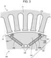
- FIG. 3 is a partial cross-sectional view illustrating the structure of an inter-pole portion of the embedded magnet rotor 100 according to the first embodiment.
- the permanent magnet housing holes 121 at adjacent poles sandwich the d axis and the center bridge 126 and are more apart from each other as they go radially outward. Therefore, in the rotor core 120, portions sandwiched by the permanent magnet housing holes 121 in the circumferential direction each form a fan-shaped portion 123 enlarged in the circumferential direction toward radially outward from the center bridge 126.
- the plurality of electromagnetic steel sheets 120a in the end plate neighboring regions 120n of the rotor core 120 each have connection portions 125 formed in fan-shaped portion end regions 123a of the fan-shaped portions 123.
- the fan-shaped portion end regions 123a here refer to portions, in the fan-shaped portions 123, on a more radially outer side than the end plate 140 and to regions near the circumferential ends of the fan-shaped portions 123.
- connection portions 125 are caulked portions 125a.
- holes are formed in electromagnetic steel sheets 120a close to the end plates 140 out of the plurality of electromagnetic steel sheets 120a, electromagnetic steel sheets 120a far from the end plates 140 are partly bent outward, and the plurality of electromagnetic steel sheets 120a are bent.
- the connection portions 125 may be formed in a unit of a group of several sheets to about ten sheets. Instead, such a group of the electromagnetic steel sheets 120a may be provided in plurality in the rotation axis direction. Instead, all the electromagnetic steel sheets 120a may be formed as a similar group.
- FIG.4 is a partial cross-sectional view illustrating an example of a conventional embedded magnet rotor for explaining the effect of the embedded magnet rotor according to the first embodiment.
- the electromagnetic steel sheets 120a in the end plate neighboring regions 120n undergo the deformation, curling, or the like at their portions in the fan-shaped portion end regions 123a, due to a force applied to the fan-shaped portions 123 ascribable to a centrifugal force applied to the permanent magnets 130 and a wind pressure ascribable to the rotation of the rotor.
- connection portions 125 are provided at the portions in the fan-shaped portion end regions 123a of at least the electromagnetic steel sheets 120a in the end plate neighboring regions 120n. This makes it possible to prevent the deformation of the end portions of the electromagnetic steel sheets forming the rotor core.
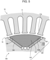
- FIG. 5 is a partial cross-sectional view illustrating the structure of an inter-pole portion of an embedded magnet rotor according to a second embodiment.
- connection portions 125 are connection portions 125 formed by the electromagnetic steel sheets 120a bonded to each other at their fan-shaped portions 123.
- the connection portions 125b are formed in at least the electromagnetic steel sheets 120a in the end plate neighboring regions 120n.
- FIG. 5 shows, as an example, the case where the bonded ranges are the entire fan-shaped portions 123, but this is not restrictive.
- the bonded ranges only need to be in portions on a more outer side than the outer peripheries of the end plates 140.
- connection portions 125 without working the electromagnetic steel sheets 120a and achieve the same effect as that of the first embodiment.
- FIG. 6 is a partial cross-sectional view illustrating the structure of an inter-pole portion of an embedded magnet rotor 100 according to a third embodiment.
- connection portions 125 are welded portions 125c.
- the welded portions 125c are formed at end portions of the fan-shaped portion end regions 123a as indicated by the broken-line ellipses in FIG. 6 .
- the welded portions 125c may be formed by spot welding at one place or a plurality of places.
- connection portions 125 In the embedded magnet rotor 100 according to this embodiment, only by spot-welding the electromagnetic steel sheets 120a, it is possible to form the connection portions 125 and achieve the same effect as that of the first embodiment.
- FIG. 7 is a cross-sectional view illustrating the structure of a rotary electric machine 200a according to a fourth embodiment. This embodiment is a modification of the first embodiment.
- the first to third embodiments describe the case where the end plates 140 are smaller in outside diameter than the rotor core 120 and the connection portions 125 are provided in the plurality of electromagnetic steel sheets 120a in the end plate neighboring regions 120n.
- end plates 141 are substantially equal in outside diameter to the rotor core 120.
- substantially equal means “equal within a range of errors including a production error, a measurement error, and so on”.
- the end plates 141 each have a nonmagnetic portion 141a and an annular insulator portion 141b disposed on the radially outer side of the nonmagnetic portion 141a.
- the annular insulator portion 141b here is an insulator, for example, a resin or a carbon compound such as silicon carbide.
- Contact surfaces between the nonmagnetic portions 141a and the annular insulator portions 141b are tapered surfaces so that a fastening force at the nonmagnetic portions 141a is transmitted to the annular insulator portions 141b.
- the tapered surfaces are on a more radially inner side from the radially outer side, in other words, become smaller in diameter.
- the nonmagnetic portions 141a and the annular insulator portions 141b may be bonded to each other by an adhesive or the like.
- the embedded magnet rotor 100a by using the end plates 141, it is possible to use conventional electromagnetic steel sheets 120a as they are and achieve the same effect as that of the first embodiment.
- stator 11: stator core, 11a: stator teeth, 12: stator winding, 12a: coil end portion, 15: gap space
- 100: embedded magnet rotor 110: rotor shaft, 110a: shaft collar, 110h: rotor shaft through hole, 120: rotor core, 120a: electromagnetic steel sheet, 120n: end plate neighboring region, 121: permanent magnet housing hole, 122: communication opening 123: fan-shaped portion, 123a: fan-shaped portion end region, 123b: entire fan-shaped portion, 123f: fan-shaped portion, 125: connection portion, 125a: caulked portion, 125b: connection portion, 125c: welded portion, 130: permanent magnet, 140: end plate, 141: end plate, 141a: nonmagnetic portion, 141b: annular insulator portion, 200: rotary electric machine
Landscapes
- Engineering & Computer Science (AREA)
- Power Engineering (AREA)
- Permanent Field Magnets Of Synchronous Machinery (AREA)
- Iron Core Of Rotating Electric Machines (AREA)
Abstract
Description
- The present invention relates to an embedded magnet rotor and a rotary electric machine including the same.
- A rotary electric machine includes: a rotor having a rotor shaft and a rotor core; and a stator provided on the radially outer side of the rotor core.
- The stator has: a stator winding being a high-voltage portion wound around stator teeth formed in a stator core. The stator winding has: portions passing through the stator core and housed in stator slots; and coil end portions protruding axially outward from the axial ends of the stator core and connected to each other.
- In the embedded magnet rotor, permanent magnets are housed in through holes formed in regions near a radially outer side in the rotor core and extending in the axial direction. The rotor core typically has a plurality of electromagnetic steel sheets laminated in the axial direction. On the axial ends of the lamination of the electromagnetic steel sheets, end plates are provided to prevent the axially outward protrusion of the permanent magnets.
- The end plates are at positions near the coil end portions of the high-pressure stator winding and thus in view of insulation, need to have a sufficient insulation distance from, that is, need to be sufficiently apart from the stator end structures. Therefore, in view of electric insulation, the end plates preferably have as small a diameter as possible. Because of this, the end plates are typically smaller in diameter than the rotor core.
- In many cases, top bridges which are part of the rotor core are present between the permanent magnet housing through holes and the outer surface of the rotor core to strengthen the structure of the rotor core. The top bridges serve as paths of magnetic flux, that is, magnetic paths. The magnetic fluxes that pass through the magnetic paths become leakage flux that stay only inside the rotor and are not linked with the stator side, leading to lower torque efficiency of the rotary electric machine. With this as a background, there are cases where a top bridgeless rotor is used. The top bridgeless rotor is of a type having no top bridges and having the permanent magnet housing spaces communicate with a space outside the rotor core (a gap space between the rotor and the stator), thereby reducing the leakage fluxes.
- Patent Document 1:
Japanese Patent No. 5447418 - In the aforesaid top bridgeless embedded magnet rotor as well, the end plates are typically smaller in diameter than the rotor core. That is, the radially outer end of the rotor core is on a more radially outer side than the radially outer ends of the end plates.
- This structure has a problem that especially in regions near the axial-direction ends of the rotor core, the electromagnetic steel sheets are deformed at their portions on a more radially outer side than the end plates by a force due to a centrifugal force applied to the permanent magnets and a wind pressure due to the rotation of the rotor, which may lead to the breakage of the rotor.
- An object of the present invention is to provide an embedded magnet rotor and a rotary electric machine in which the deformation of end portions of electromagnetic steel sheets forming a rotor core is prevented.
- According to the present invention, there is provided an embedded magnet rotor comprising: a rotor shaft extending in a rotation axis direction; a rotor core having a plurality of electromagnetic steel sheets laminated in the rotation axis direction attached to a radially outer side of the rotor shaft, the rotor core having two permanent magnet housing holes that are formed in a radially outer portion of the rotor core and are arranged in a V-shape across each d axis with an interval in a circumferential direction; plate-shaped permanent magnets respectively housed in the permanent magnet housing holes; and two end plates smaller in outside diameter than the rotor core and arranged at ends of the plurality of electromagnetic steel sheets in terms of the rotation axis direction to prevent the permanent magnets from protruding outward in terms of the rotation axis direction, wherein the permanent magnet housing holes communicate with an outer side of an outer peripheral surface of the rotor core, and wherein the plurality of electromagnetic steel sheets in regions near the end plates in terms of the rotation axis direction of the rotor core have connection portions for connecting the electromagnetic steel sheets.
-
-
FIG. 1 is a cross-sectional view illustrating the structure of a rotary electric machine according to a first embodiment. -
FIG. 2 is a sectional longitudinal view illustrating the structure of the rotary electric machine according to the first embodiment. -
FIG. 3 is a partial cross-sectional view illustrating an inter-pole portion of the embedded magnet rotor according to the first embodiment. -
FIG. 4 is a partial cross-sectional view illustrating an example of a conventional embedded magnet rotor for explaining the effect of the embedded magnet rotor according to the first embodiment. -
FIG. 5 is a partial cross-sectional view illustrating the structure of an inter-pole portion of an embedded magnet rotor according to a second embodiment. -
FIG. 6 is a partial cross-sectional view illustrating the structure of an inter-pole portion of an embedded magnet rotor according to a third embodiment. -
FIG. 7 is a cross-sectional view illustrating the structure of a rotary electric machine according to a fourth embodiment. - Hereinafter, with reference to the accompanying drawings, embodiments of an embedded magnet rotor and a rotary electric machine of the present invention will be described. The same or similar portions are represented by the same reference symbols, and a duplicate description will be omitted.
-
FIG. 1 is a cross-sectional view illustrating the structure of a rotaryelectric machine 200 according to a first embodiment.FIG. 2 is a sectional longitudinal view illustrating the structure of the rotaryelectric machine 200 according to the first embodiment. - The rotary
electric machine 200 includes: an embeddedmagnet rotor 100 having arotor shaft 110 extending in the rotation axis direction, arotor core 120 attached to therotor shaft 110, and a plurality of permanent magnets 130 (refer toFIG. 3 ); astator 10 disposed on the radially outer side of therotor core 120 to surround therotor core 120 via agap space 15 and having acylindrical stator core 11 wherestator teeth 11a are formed; and two bearings (not illustrated) by which therotor shaft 110 is rotatably supported. - The
rotor core 120 has a plurality ofelectromagnetic steel sheets 120a laminated in the rotation axis direction. Theelectromagnetic steel sheets 120a each have a punched portion where therotor shaft 110 is to penetrate and punched portions where thepermanent magnets 130 are to penetrate. In the state in which theelectromagnetic steel sheets 120a are laminated, these punched portions form, in therotor core 120, a rotor shaft throughhole 110h (FIG. 2 ) and a plurality of permanent magnet housing holes 121 (FIG. 1 ) which both extend in the rotation axis direction. - Two permanent
magnet housing holes 121 are arranged across each axis d and eachcenter bridge 126, in a V-shape projecting radially inward. Note that thoughFIG. 1 illustrates, as an example, the case where there is only one layer of the V-shaped arrangement in the radial direction, this is not restrictive and the V-shaped arrangement may be formed in a plurality of layers in the radial direction. - The
permanent magnets 130 are plate-shaped. ThoughFIG. 1 illustrates, as an example, the case where thepermanent magnets 130 are flat plate-shaped, thepermanent magnets 130 may have, for example, a curved shape in its cross section perpendicular to the rotation axis of the rotor shaft 110 (vertical cross section). - On the rotation axis-direction ends of the
rotor core 120, twoend plates 140 are provided to prevent thepermanent magnets 130 from protruding from therotor core 120 outward in terms of the rotation axis direction. Theend plates 140 are smaller in outside diameter than therotor core 120 because of reasons such as that they only need to cover a range where thepermanent magnets 130 are arranged in the vertical cross section and they need to have as large an insulation distance as possible from later-describedcoil end portions 12a to which a high voltage is applied. Further, theend plates 140 are larger in outside diameter than a radially outermost envelope cylinder of thepermanent magnets 130 housed in therotor core 120. - Regions close to the
end plates 140 in therotor core 120 is to be called endplate neighboring regions 120n (FIG. 2 ). Here, the endplate neighboring regions 120n are ranges of theelectromagnetic steel sheets 120a wherein the deformation of radially outer portions of theelectromagnetic steel sheets 120a and the breakage of the rotor are conventionally likely to occur because theend plates 140 are smaller in outside diameter than therotor core 120. - On the inner peripheral side of the
stator 10, the plurality ofstator teeth 11 for a stator winding 12 (FIG. 2 ) are formed with intervals in the circumferential direction. The stator winding 12 has thecoil end portions 12a extending from the ends of thestator core 11 outward in terms of the rotation axis direction. -
FIG. 3 is a partial cross-sectional view illustrating the structure of an inter-pole portion of the embeddedmagnet rotor 100 according to the first embodiment. - The permanent
magnet housing holes 121 at adjacent poles sandwich the d axis and thecenter bridge 126 and are more apart from each other as they go radially outward. Therefore, in therotor core 120, portions sandwiched by the permanentmagnet housing holes 121 in the circumferential direction each form a fan-shaped portion 123 enlarged in the circumferential direction toward radially outward from thecenter bridge 126. - The plurality of
electromagnetic steel sheets 120a in the endplate neighboring regions 120n of therotor core 120 each haveconnection portions 125 formed in fan-shapedportion end regions 123a of the fan-shaped portions 123. - The fan-shaped
portion end regions 123a here refer to portions, in the fan-shaped portions 123, on a more radially outer side than theend plate 140 and to regions near the circumferential ends of the fan-shaped portions 123. - In this embodiment, the
connection portions 125 are caulkedportions 125a. For example, as illustrated inFIG. 3 , holes are formed inelectromagnetic steel sheets 120a close to theend plates 140 out of the plurality ofelectromagnetic steel sheets 120a,electromagnetic steel sheets 120a far from theend plates 140 are partly bent outward, and the plurality ofelectromagnetic steel sheets 120a are bent. For example, theconnection portions 125 may be formed in a unit of a group of several sheets to about ten sheets. Instead, such a group of theelectromagnetic steel sheets 120a may be provided in plurality in the rotation axis direction. Instead, all theelectromagnetic steel sheets 120a may be formed as a similar group. -
FIG.4 is a partial cross-sectional view illustrating an example of a conventional embedded magnet rotor for explaining the effect of the embedded magnet rotor according to the first embodiment. - In the conventional example, the
electromagnetic steel sheets 120a in the endplate neighboring regions 120n undergo the deformation, curling, or the like at their portions in the fan-shapedportion end regions 123a, due to a force applied to the fan-shapedportions 123 ascribable to a centrifugal force applied to thepermanent magnets 130 and a wind pressure ascribable to the rotation of the rotor. - In the embedded
magnet rotor 100 according to this embodiment, with its conventional shape left as it is, theconnection portions 125 are provided at the portions in the fan-shapedportion end regions 123a of at least theelectromagnetic steel sheets 120a in the endplate neighboring regions 120n. This makes it possible to prevent the deformation of the end portions of the electromagnetic steel sheets forming the rotor core. -
FIG. 5 is a partial cross-sectional view illustrating the structure of an inter-pole portion of an embedded magnet rotor according to a second embodiment. - This embodiment is a modification of the first embodiment. In this embodiment, the
connection portions 125 areconnection portions 125 formed by theelectromagnetic steel sheets 120a bonded to each other at their fan-shapedportions 123. Theconnection portions 125b are formed in at least theelectromagnetic steel sheets 120a in the endplate neighboring regions 120n. -
FIG. 5 shows, as an example, the case where the bonded ranges are the entire fan-shapedportions 123, but this is not restrictive. In theelectromagnetic steel sheets 120a, the bonded ranges only need to be in portions on a more outer side than the outer peripheries of theend plates 140. - In the embedded
magnet rotor 100 according to this embodiment, only by applying an adhesive, it is possible to form theconnection portions 125 without working theelectromagnetic steel sheets 120a and achieve the same effect as that of the first embodiment. -
FIG. 6 is a partial cross-sectional view illustrating the structure of an inter-pole portion of an embeddedmagnet rotor 100 according to a third embodiment. - This embodiment is a modification of the first embodiment. In this embodiment, the
connection portions 125 are weldedportions 125c. In at least theelectromagnetic steel sheets 120a in the endplate neighboring regions 120n, the weldedportions 125c are formed at end portions of the fan-shapedportion end regions 123a as indicated by the broken-line ellipses inFIG. 6 . The weldedportions 125c may be formed by spot welding at one place or a plurality of places. - In the embedded
magnet rotor 100 according to this embodiment, only by spot-welding theelectromagnetic steel sheets 120a, it is possible to form theconnection portions 125 and achieve the same effect as that of the first embodiment. -
FIG. 7 is a cross-sectional view illustrating the structure of a rotaryelectric machine 200a according to a fourth embodiment. This embodiment is a modification of the first embodiment. - The first to third embodiments describe the case where the
end plates 140 are smaller in outside diameter than therotor core 120 and theconnection portions 125 are provided in the plurality ofelectromagnetic steel sheets 120a in the endplate neighboring regions 120n. - On the other hand, in an embedded
magnet rotor 100a of the rotaryelectric machine 200a according to this embodiment,end plates 141 are substantially equal in outside diameter to therotor core 120. Here, "substantially equal" means "equal within a range of errors including a production error, a measurement error, and so on". - The
end plates 141 each have anonmagnetic portion 141a and anannular insulator portion 141b disposed on the radially outer side of thenonmagnetic portion 141a. Theannular insulator portion 141b here is an insulator, for example, a resin or a carbon compound such as silicon carbide. - Contact surfaces between the
nonmagnetic portions 141a and theannular insulator portions 141b are tapered surfaces so that a fastening force at thenonmagnetic portions 141a is transmitted to theannular insulator portions 141b. As they go from the outer side toward the inner side (rotor core 120 side) of theend plates 141 in terms of the rotation axis direction, the tapered surfaces are on a more radially inner side from the radially outer side, in other words, become smaller in diameter. Thenonmagnetic portions 141a and theannular insulator portions 141b may be bonded to each other by an adhesive or the like. - As described above, in the embedded
magnet rotor 100a according to this embodiment, by using theend plates 141, it is possible to use conventionalelectromagnetic steel sheets 120a as they are and achieve the same effect as that of the first embodiment. - According to the embodiments described above, it is possible to provide the embedded magnet rotor and the rotary electric machine in which the deformation of the end portions of the electromagnetic steel sheets forming the rotor core is prevented.
- While embodiment of the present invention has been described, the embodiment has been presented by way of example only, and is not intended to limit the scope of the invention. Features of the embodiment may be used in combination. Furthermore, the embodiment may be embodied in other various forms. Various omissions, replacements and changes may be made without departing from the spirit of the invention. The embodiment and variants thereof are within the scope and spirit of the invention, and are similarly within the scope of the invention defined in the appended claims and the range of equivalency thereof.
- 10: stator, 11: stator core, 11a: stator teeth, 12: stator winding, 12a: coil end portion, 15: gap space, 100: embedded magnet rotor, 110: rotor shaft, 110a: shaft collar, 110h: rotor shaft through hole, 120: rotor core, 120a: electromagnetic steel sheet, 120n: end plate neighboring region, 121: permanent magnet housing hole, 122: communication opening 123: fan-shaped portion, 123a: fan-shaped portion end region, 123b: entire fan-shaped portion, 123f: fan-shaped portion, 125: connection portion, 125a: caulked portion, 125b: connection portion, 125c: welded portion, 130: permanent magnet, 140: end plate, 141: end plate, 141a: nonmagnetic portion, 141b: annular insulator portion, 200: rotary electric machine
Claims (7)
- An embedded magnet rotor comprising:a rotor shaft extending in a rotation axis direction;a rotor core having a plurality of electromagnetic steel sheets laminated in the rotation axis direction attached to a radially outer side of the rotor shaft, the rotor core having two permanent magnet housing holes that are formed in a radially outer portion of the rotor core and are arranged in a V-shape across each d axis with an interval in a circumferential direction;plate-shaped permanent magnets respectively housed in the permanent magnet housing holes; andtwo end plates smaller in outside diameter than the rotor core and arranged at ends of the plurality of electromagnetic steel sheets in terms of the rotation axis direction to prevent the permanent magnets from protruding outward in terms of the rotation axis direction,wherein the permanent magnet housing holes communicate with an outer side of an outer peripheral surface of the rotor core, andwherein the plurality of electromagnetic steel sheets in regions near the end plates in terms of the rotation axis direction of the rotor core have connection portions for connecting the electromagnetic steel sheets.
- The embedded magnet rotor according to claim 1, wherein the two end plates are larger in outside diameter than a radially outermost envelope cylinder of the permanent magnets housed in the rotor core.
- The embedded magnet rotor according to claim 1 or 2, wherein the connection portions are caulked portions formed in radial and circumferential end portions of the plurality of electromagnetic steel sheets in the regions near the end plates.
- The embedded magnet rotor according to claim 1 or 2, wherein the connection portions are welded portions formed in radial and circumferential end portions of the plurality of electromagnetic steel sheets in the regions near the end plates.
- The embedded magnet rotor according to claim 1 or claim 2, wherein the connection portions are bonded portions formed in at least radial and circumferential end portions of the plurality of electromagnetic steel sheets in the regions near the end plates.
- An embedded magnet rotor comprising:a rotor shaft extending in a rotation axis direction;a rotor core having a plurality of electromagnetic steel sheets laminated in the rotation axis direction attached to a radially outer side of the rotor shaft, the rotor core having two permanent magnet housing holes that are formed in a radially outer portion of the rotor core and are arranged in a V-shape across each d axis with an interval in a circumferential direction;plate-shaped permanent magnets housed respectively in the permanent magnet housing holes; andtwo end plates substantially equal in outside diameter to the rotor core and each having an annular insulator portion in a radially outer portion of the end plates.
- A rotary electric machine comprising:the embedded magnet rotor according to any one of claim 1 to claim 6; anda stator disposed on a radially outer side of the rotor core.
Applications Claiming Priority (1)
| Application Number | Priority Date | Filing Date | Title |
|---|---|---|---|
| PCT/JP2022/016987 WO2023188423A1 (en) | 2022-04-01 | 2022-04-01 | Interior permanent magnet rotor and rotating electric machine |
Publications (2)
| Publication Number | Publication Date |
|---|---|
| EP4507168A1 true EP4507168A1 (en) | 2025-02-12 |
| EP4507168A4 EP4507168A4 (en) | 2025-12-31 |
Family
ID=88192462
Family Applications (1)
| Application Number | Title | Priority Date | Filing Date |
|---|---|---|---|
| EP22809631.9A Withdrawn EP4507168A4 (en) | 2022-04-01 | 2022-04-01 | INTERNAL PERMANENT MAGNETIC ROTOR AND ELECTRIC LATHE |
Country Status (5)
| Country | Link |
|---|---|
| US (1) | US20230318379A1 (en) |
| EP (1) | EP4507168A4 (en) |
| JP (1) | JP7631367B2 (en) |
| CN (1) | CN117157852A (en) |
| WO (1) | WO2023188423A1 (en) |
Family Cites Families (13)
| Publication number | Priority date | Publication date | Assignee | Title |
|---|---|---|---|---|
| JPH11146582A (en) * | 1997-11-07 | 1999-05-28 | Aichi Emerson Electric Co Ltd | Embedded magnet type rotor |
| JP2004096978A (en) * | 2002-09-04 | 2004-03-25 | Daikin Ind Ltd | Permanent magnet embedded motor and rotary compressor |
| JP4644875B2 (en) * | 2004-04-12 | 2011-03-09 | アイシン精機株式会社 | End plates used for motors and rotors of motors |
| JP2010011621A (en) * | 2008-06-26 | 2010-01-14 | Toyota Motor Corp | End plate for rotating electrical machine |
| JP2011125163A (en) * | 2009-12-11 | 2011-06-23 | Toyota Motor Corp | Motor rotor |
| KR101307097B1 (en) * | 2010-03-15 | 2013-09-11 | 도요타지도샤가부시키가이샤 | Rotor and method of manufacturing the rotor |
| US9154005B2 (en) * | 2010-06-14 | 2015-10-06 | Toyota Jidosha Kabushiki Kaisha | Rotor core for rotating electrical machine, and manufacturing method thereof |
| JP5447418B2 (en) * | 2011-03-28 | 2014-03-19 | 株式会社豊田自動織機 | Rotating electric machine permanent magnet embedded rotor and rotating electric machine |
| JP5786804B2 (en) * | 2012-06-13 | 2015-09-30 | 株式会社デンソー | Rotor for rotating electrical machine and method for manufacturing the same |
| JP2015202027A (en) * | 2014-03-31 | 2015-11-12 | ダイキン工業株式会社 | Rotor |
| EP3145057B1 (en) * | 2014-05-15 | 2022-05-04 | Fuji Electric Co., Ltd. | Permanent magnet embedded rotating electrical machine |
| JP6525329B2 (en) * | 2016-03-04 | 2019-06-05 | 本田技研工業株式会社 | Rotor and method of manufacturing rotor |
| JP2020014322A (en) * | 2018-07-18 | 2020-01-23 | 日立オートモティブシステムズ株式会社 | Rotating electric machine rotor and rotating electric machine |
-
2022
- 2022-04-01 WO PCT/JP2022/016987 patent/WO2023188423A1/en not_active Ceased
- 2022-04-01 CN CN202280003608.2A patent/CN117157852A/en not_active Withdrawn
- 2022-04-01 EP EP22809631.9A patent/EP4507168A4/en not_active Withdrawn
- 2022-04-01 JP JP2022561119A patent/JP7631367B2/en active Active
- 2022-12-09 US US18/064,103 patent/US20230318379A1/en not_active Abandoned
Also Published As
| Publication number | Publication date |
|---|---|
| CN117157852A (en) | 2023-12-01 |
| WO2023188423A1 (en) | 2023-10-05 |
| JP7631367B2 (en) | 2025-02-18 |
| US20230318379A1 (en) | 2023-10-05 |
| EP4507168A4 (en) | 2025-12-31 |
| JPWO2023188423A1 (en) | 2023-10-05 |
Similar Documents
| Publication | Publication Date | Title |
|---|---|---|
| US20080278021A1 (en) | Stress Distributing Permanent Magnet Rotor Geometry For Electric Machines | |
| JP5301868B2 (en) | Embedded magnet type motor | |
| US11165293B2 (en) | Rotor and motor | |
| CN116636116A (en) | Rotor core | |
| JP4515236B2 (en) | Embedded magnet type rotor | |
| US12266978B2 (en) | Flux concentrate type rotor and motor having the same | |
| WO2017195498A1 (en) | Rotor and rotary electric machine | |
| JP2009136090A (en) | Rotor plate | |
| JP2022176781A (en) | rotor | |
| US20240195242A1 (en) | Motor | |
| US20230318379A1 (en) | Embedded magnet rotor and rotary electric machine | |
| CN118044098A (en) | Rotor | |
| WO2021131298A1 (en) | Rotary electric machine | |
| CN110720169B (en) | Rotor structure of motor | |
| US20240171022A1 (en) | Motor | |
| JPH09289745A (en) | Rotating machine magnetic pole stack | |
| JP7124247B1 (en) | Rotor of rotary electric machine | |
| JP2012170231A (en) | End plate and rotor for synchronous reluctance motor using the same | |
| WO2022009774A1 (en) | Rotating electric machine and method for manufacturing rotating electric machine | |
| JP5256835B2 (en) | Rotating electric machine stator and rotating electric machine | |
| WO2022044090A1 (en) | Rotor | |
| US11784524B2 (en) | Rotor and rotary electric machine | |
| US20240055918A1 (en) | Permanent magnet rotor and permanent magnet rotary electric machine | |
| US12294243B2 (en) | Rotating electric machine | |
| JP7418663B2 (en) | Rotor and rotor manufacturing method |
Legal Events
| Date | Code | Title | Description |
|---|---|---|---|
| STAA | Information on the status of an ep patent application or granted ep patent |
Free format text: STATUS: UNKNOWN |
|
| STAA | Information on the status of an ep patent application or granted ep patent |
Free format text: STATUS: THE INTERNATIONAL PUBLICATION HAS BEEN MADE |
|
| PUAI | Public reference made under article 153(3) epc to a published international application that has entered the european phase |
Free format text: ORIGINAL CODE: 0009012 |
|
| STAA | Information on the status of an ep patent application or granted ep patent |
Free format text: STATUS: REQUEST FOR EXAMINATION WAS MADE |
|
| 17P | Request for examination filed |
Effective date: 20221202 |
|
| AK | Designated contracting states |
Kind code of ref document: A1 Designated state(s): AL AT BE BG CH CY CZ DE DK EE ES FI FR GB GR HR HU IE IS IT LI LT LU LV MC MK MT NL NO PL PT RO RS SE SI SK SM TR |
|
| DAV | Request for validation of the european patent (deleted) | ||
| DAX | Request for extension of the european patent (deleted) | ||
| RAP1 | Party data changed (applicant data changed or rights of an application transferred) |
Owner name: KABUSHIKI KAISHA TOSHIBA |
|
| REG | Reference to a national code |
Ref country code: DE Ref legal event code: R079 Free format text: PREVIOUS MAIN CLASS: H02K0001220000 Ipc: H02K0001276000 |
|
| A4 | Supplementary search report drawn up and despatched |
Effective date: 20251203 |
|
| RIC1 | Information provided on ipc code assigned before grant |
Ipc: H02K 1/276 20220101AFI20251127BHEP Ipc: H02K 15/0278 20250101ALN20251127BHEP |
|
| STAA | Information on the status of an ep patent application or granted ep patent |
Free format text: STATUS: THE APPLICATION HAS BEEN WITHDRAWN |
|
| 18W | Application withdrawn |
Effective date: 20260209 |