EP4507142A2 - Installationsdose und verfahren zur herstellung einer installationsdose - Google Patents
Installationsdose und verfahren zur herstellung einer installationsdose Download PDFInfo
- Publication number
- EP4507142A2 EP4507142A2 EP24193190.6A EP24193190A EP4507142A2 EP 4507142 A2 EP4507142 A2 EP 4507142A2 EP 24193190 A EP24193190 A EP 24193190A EP 4507142 A2 EP4507142 A2 EP 4507142A2
- Authority
- EP
- European Patent Office
- Prior art keywords
- installation
- installation box
- box
- side wall
- axial direction
- Prior art date
- Legal status (The legal status is an assumption and is not a legal conclusion. Google has not performed a legal analysis and makes no representation as to the accuracy of the status listed.)
- Pending
Links
Images

Classifications
-
- H—ELECTRICITY
- H02—GENERATION; CONVERSION OR DISTRIBUTION OF ELECTRIC POWER
- H02G—INSTALLATION OF ELECTRIC CABLES OR LINES, OR OF COMBINED OPTICAL AND ELECTRIC CABLES OR LINES
- H02G3/00—Installations of electric cables or lines or protective tubing therefor in or on buildings, equivalent structures or vehicles
- H02G3/02—Details
- H02G3/08—Distribution boxes; Connection or junction boxes
- H02G3/12—Distribution boxes; Connection or junction boxes for flush mounting
- H02G3/121—Distribution boxes; Connection or junction boxes for flush mounting in plain walls
-
- H—ELECTRICITY
- H02—GENERATION; CONVERSION OR DISTRIBUTION OF ELECTRIC POWER
- H02G—INSTALLATION OF ELECTRIC CABLES OR LINES, OR OF COMBINED OPTICAL AND ELECTRIC CABLES OR LINES
- H02G3/00—Installations of electric cables or lines or protective tubing therefor in or on buildings, equivalent structures or vehicles
- H02G3/02—Details
- H02G3/08—Distribution boxes; Connection or junction boxes
- H02G3/081—Bases, casings or covers
- H02G3/083—Inlets
- H02G3/085—Inlets including knock-out or tear-out sections
Definitions
- the present invention relates to an installation box for electrical installations and a method for producing an installation box.
- Installation boxes are used, among other things, to install electrical switches, sockets, lamps, devices, etc. at the designated locations in a building.
- Such installation boxes include, for example, flush-mounted boxes, inlet boxes, flush-mounted junction boxes, distribution boxes and the like.
- the installation boxes typically have a cylindrical or cuboid-shaped box body with a box base and a tubular side wall extending in an axial direction. These include an installation space accessible via an installation opening.
- installation boxes are usually manufactured by injection molding, or the installation boxes include or consist of injection molding materials. If such installation boxes are closed at the back and thus include a box base that merges into the side wall and is molded onto it, the installation space, viewed from the axial direction, is usually within a (clear) cross-section, or an inner contour of the installation opening.
- An example of such installation boxes is the EP3540885
- This design of the installation box enables easy production by injection molding with a core which is arranged in the installation space and can be demolded through the installation opening.
- a disadvantage of such installation boxes is that only a limited installation space is available and the connection of the electrical installations can be cumbersome depending on the application.
- Installation boxes are also known which have a rear mounting opening instead of a rear box base.
- An example of such installation boxes is the EP3584898 the same applicant.
- the installation box can alternatively be demolded via the mounting opening and not via the installation opening.
- the size of the installation space is determined in this case by the rear mounting opening.
- such installation boxes have the disadvantage that the mounting opening must be provided with a cover and possibly a seal. This therefore leads to another required assembly step or production step (manufacturing and attaching the cover). This can also lead to increased manufacturing costs.
- the installation box comprises a box body with a tubular side wall extending in an axial direction from a front end to a rear end.
- the tubular side wall extends around a central axis of the installation box, which consequently also extends in the axial direction.
- the tubular side wall surrounds an installation space which is accessible via a front installation opening of the box body bordered by the tubular side wall.
- the tubular side wall can change its cross-section along the axial direction.
- the tubular side wall can be round and/or square in sections when viewed from the axial direction.
- the tubular side wall also merges into a box base of the box body at the rear end.
- the box base is therefore opposite the installation opening.
- the box body (comprising the side wall and the box base) is advantageously designed as a single piece.
- the box body, or the tubular side wall, viewed from the axial direction, forms at least one pocket that projects radially outward over an inner contour of the installation opening.
- several pockets are present.
- the pocket forms a pocket interior, which is part of the installation space.
- the expanded cross-section of the installation space provided by the pocket can, for example, accommodate excess lengths of installation cables without reducing the intended space for the actual electrical installation (e.g. socket or similar).
- the box body can consist of a hard plastic component.
- the box body advantageously has at least one layer of a hard plastic component that surrounds the installation space.
- the layer of the hard plastic component protects the installation space and preferably keeps it dimensionally stable, or the pocket is preferably dimensionally stable.
- a dimensionally stable pocket can protect the electrical installation from damage, for example if external forces are exerted on the installation box. Dimensionally stable means that the pocket cannot be pressed in or turned inside out.
- the box body can also have at least one insertion opening for inserting installation cables and/or installation pipes into the installation space.
- the installation opening can also be closed by a cover of the installation box, or the installation box can have a cover for closing the installation opening.
- the installation box can also have additional elements and/or layers made of a soft elastic material component, such as a soft elastic membrane closing the insertion opening and/or a seal for sealing the cover against the box body.
- the elements made of the soft elastic material component are advantageously molded onto the box body and/or the cover. It is also conceivable for the installation box to comprise at least one further layer made of a different material, such as a layer made of intumescent material, which is molded or attached at least in part to the box body made of the hard plastic component.
- the box body can have at least one insertion opening.
- the insertion opening can also be closed in an initial state (i.e. before assembly and/or in the state for sale) by the soft-elastic (pierceable) membrane or a removable wall area.
- At least one insertion opening of the box body is advantageously arranged in the at least one pocket.
- the expanded cross-section of the installation space provided by the pocket can thus also accommodate installation pipe ends protruding into the installation space.
- a locking element for fastening an electrical installation pipe can be provided in the pocket and on the at least one insertion opening. The pocket therefore enables installation pipes and/or installation cables to be easily mounted on the installation box.
- the pocket advantageously has a substantially constant pocket depth in the axial direction at a circumferential position.
- the pocket can alternatively or additionally adjoin the box base.
- the pocket depth is measured from the axial direction from the inner contour of the installation opening radially outwards to the inside of the pocket.
- the pocket can also be curved outwards (pointing away from the central axis).
- two structured surface elements can be arranged on the inside of the installation box, which provide an engagement surface for spreading claws of an electrical installation.
- the pocket is advantageously arranged in the circumferential direction next to and/or in the axial direction below the surface elements.
- the pocket gives the installation space a variable cross-section in the axial direction.
- this can therefore have (at least) a first cross-section normal to the axial direction and in a rear area of the installation space, it can have (at least) a second cross-section that is larger than the first cross-section.
- first cross-sections in the front area can also be several first cross-sections in the front area and several second cross-sections in the rear area.
- the front area of the installation space can be surrounded by the front end of the tubular side wall and/or the rear area of the installation space can be surrounded by the rear end of the tubular side wall.
- the front area advantageously extends over 5% - 40% of a length of the can body in the axial direction and/or the rear area over 60 - 95% of the length of the can body. In particular, however, the front area extends over 5% - 20% of the length of the can body and/or the rear area over 80 - 95% of the length of the can body.
- the (at least one) second cross-section can have at least one outwardly curved section which lies radially outside the first cross-section. The outwardly curved section of the (at least one) second cross-section lies in the outwardly curved pocket of the installation space, as described in more detail above.
- At least one wall area that can be separated along a defined contour can be arranged in the tubular side wall.
- the at least one detachable wall area can be integrated into the axial direction.
- two removable wall areas are advantageously present. These are preferably arranged opposite one another in relation to the central axis of the tubular side wall.
- the two wall areas arranged opposite one another can be oriented parallel to one another.
- the installation box advantageously comprises two removable wall areas between which the at least one pocket is arranged in the circumferential direction of the side wall.
- Fastening elements for fastening an electrical installation in the installation box can also be arranged at the front end of the tubular side wall. These can protrude into the installation space and/or into the installation opening. This means that they can be arranged, in particular molded, on an inner side of the tubular side wall.
- the installation box can further comprise a latching structure for operatively connecting a counter-latching structure of another installation box.
- the latching structure is advantageously arranged on an outside of the tubular side wall.
- the latching structure can also be arranged on the cover closing the installation opening.
- the latching structure can comprise one or more latching elements, which advantageously have an undercut in the (respective) connection direction.
- the connection direction is the direction from which another installation box is moved towards the installation box for operatively connecting the counter-latching structure with the latching structure.
- the latching structure advantageously has at least one pair of latching elements.
- a pair of latching elements comprises a first and a second locking element.
- the first and second locking elements of a pair of locking elements are preferably arranged opposite one another in a circumferential direction of the installation box in relation to the (corresponding) removable wall area.
- the first and the second locking elements can each have an undercut.
- the first locking element is advantageously designed to be operatively connected to a second locking element of the counter-locking structure of the further installation box, wherein the second locking element of the counter-locking structure is identical in construction to the second locking element of the locking structure.
- the second locking element can be designed to be operatively connected to a first locking element of the counter-locking structure, wherein the first locking element of the counter-locking structure is identical in construction to the first locking element of the locking structure.
- the at least one first locking element can be designed without undercuts in a first direction (y-direction), which is arranged perpendicular to the axial direction (x-direction) and perpendicular to the connection direction (z-direction).
- the at least one second locking element can in turn be designed without undercuts in a second direction opposite to the first direction (negative y-direction). This is particularly advantageous when producing the installation box by injection molding.
- the removable wall area can comprise several separate or joint removable sections. Depending on the application, the several Sections are arranged one behind the other in the axial direction. Each detachable section can be surrounded by a seal at least in part. Alternatively or additionally, the seal can also surround several sections together at least in part. There can be at least one pair of locking elements per section. This means that there are then first and second locking elements opposite each other in relation to this section.
- At least two sections can be arranged one behind the other in the axial direction (a front section and a rear section and optionally at least one middle section).
- the front section can be adjacent to the installation opening.
- the previously mentioned fastening elements can be arranged on an inner side of the front section, which faces the installation space.
- the fastening elements are advantageously molded onto the respective front section.
- the fastening elements can also be removed by cutting out the front sections.
- a pipe inlet can be arranged in one or more sections, in particular in the rear and/or (if present) the middle section.
- the respective pipe inlet can be closed by a removable or pierceable soft-elastic membrane.
- the present installation box comprises at least one injection-molded material component.
- the installation box advantageously consists of at least one injection-molded material component, in particular a hard plastic component.
- the installation box can also comprise several injection-molded material components.
- the installation box can comprise at least two injection-molded material components, such as the hard plastic component and the soft elastic material component or the hard plastic component and an intumescent material component.
- the present invention further relates to a method for producing an installation box for electrical installations.
- the installation box has a box body made of a hard plastic component with a tubular side wall extending in an axial direction from a front end to a rear end, which surrounds an installation space.
- the installation space is accessible via an installation opening on the front edged by the tubular side wall.
- Opposite the installation opening is a box base of the box body.
- the tubular side wall also forms at least one pocket that protrudes outward beyond an inner contour of the installation opening.
- the pocket forms a pocket interior, which is part of the installation space.
- the said installation box is manufactured by injection molding, wherein after the installation box has been injection molded, it is demolded by a folding core arranged in the installation space, which can be removed from the front through the installation opening.
- the folding core is variable in its cross-section at a distal end of the folding core, in particular in its cross-section normal to the axial Direction.
- the axial direction of the installation box corresponds to the demolding direction of the folding core.
- the folding core can advantageously be adjustable from a first position to a second position.
- the distal end of the folding core can have a first outer contour when viewed from the axial direction and a second outer contour when viewed from the axial direction.
- only the second outer contour lies within the inner contour of the installation opening.
- the distal end of the folding core is the end of the folding core that is arranged in the installation space after the installation box has been molded. In other words: the distal end is the part of the folding core that has to be demolded from the installation box after it has been sharpened.
- the method according to the invention can therefore comprise the method step whereby the folding core is in the first position during injection molding, is brought into the second position after injection molding, before the folding core, which is arranged in the installation space in some areas (i.e. with its distal end) after injection molding, is demolded through the installation opening in the axial direction of the installation box.
- the installation box has elements or layers made of the soft-elastic material component (such as a membrane closing the insertion opening and/or a seal)
- the installation box is manufactured using a 2-component injection molding process.
- the process can therefore include the further process step of firstly molding the box body from the Hard plastic component is injected and then additional elements and/or layers made of a soft elastic material component are injected onto the can body (such as a membrane closing the insertion openings of the can body made of the hard plastic component and/or a seal).
- the folding core preferably remains arranged in the installation space during the injection molding of the hard plastic component and the injection molding of the soft elastic material component and is only then removed from the front through the installation opening.
- the folding core can have a base and at least one segment that can be moved relative to the base.
- the number of movable segments can correspond to the number of pockets in the installation space described above. If several segments are present, these can be operatively connected to one another.
- the base preferably has a sliding surface along which a corresponding sliding surface of the segment can slide when the folding core is moved from the first position to the second position (or vice versa).
- the folding core can also have a control system that controls the unfolding and folding back movements of the folding core. This control system can be electronic, pneumatic or hydraulic.
- the first outer contour and the second outer contour of the distal end of the folding core have at least three positioning corners, which keep their respective position unchanged in the first and second position of the folding core.
- the folding core advantageously comprises at least four positioning corners.
- the positioning corners are preferably arranged at the base of the folding core. This means that the base of the folding core can be in contact with the installation box. The positioning corners are used to position the injection-molded installation box when the folding core is demolded.
- the installation box can have fastening elements in the area of the front end of the tubular side wall for fastening an electrical installation in the installation box, which protrude into the installation space and/or into the installation opening.
- the second outer contour of the distal end of the folding core can be reduced in size normal to the axial direction in such a way that it can be demolded from the installation opening and past the fastening elements.
- the folding core can have further (movable) segments which fill the installation space behind the respective fastening elements during injection molding.
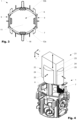
- Figure 1 shows a first variant of an installation box 1 according to the invention in a perspective view, while Figure 2 this installation box 1 in a view from the side and Figure 3 in a top view.
- the installation box 1 shown comprises a box body 2 with a tubular side wall 3 extending in an axial direction (x-direction) from a front end 4 to a rear end 5.
- the tubular side wall 3 surrounds an installation space 6. This is accessible via a front installation opening 7 bordered by the tubular side wall 3.
- a box base 11 of the box body 2 Opposite the installation opening 7 there is a box base 11 of the box body 2, which merges into the tubular side wall 3.
- the tubular side wall 3 viewed from the axial direction, forms at least one pocket 15 projecting outward over an inner contour of the installation opening 7.
- the pocket 15 is U-shaped.
- the installation space 6 therefore has a variable cross-section in the axial direction. In the front area 13 of the installation space 6, this has (at least) a first cross-section normal to the axial direction and in the rear area 14 of the installation space 6, it has (at least) a second cross-section that is larger in relation to the first cross-section.
- Two wall regions 9 of the tubular side wall 3 are arranged between the two opposing pockets 15. These can be separated along a defined contour 8. In the present case, the two wall regions 9 are opposite one another in relation to the central axis of the tubular side wall 3.
- the detachable wall area 9 can comprise several separate or common detachable sections 16.
- the three sections 16a, 16b 16c are arranged one behind the other in the axial direction.
- the middle section 16b and the rear section 16c each have a detachable membrane 17.
- Fastening elements 18 which protrude into the installation space 6 or into the installation opening 7 can be formed on an inner side of the front section 16a.
- a locking structure 10 can also be seen on an outer side of the tubular side wall 3.
- the locking structure 10 serves to operatively connect a counter-locking structure of another installation box from a connection direction (z direction).
- the locking structure 10 can comprise at least one pair of locking elements (per detachable wall area 9) with a first and a second locking element 19, 20.
- FIG 4 shows an installation box 1 with a schematically shown folding core 21 shortly after the production of the installation box 1 by injection molding. While the folding core 21 is still arranged with a distal end 22 in the installation space 6 of the installation box 1 during injection molding, this is the injection molding through the installation opening 7.
- the folding core 21 is in a first position.
- the folding core 21 is then moved from the first position to a second position.
- the distal end 22 of the folding core 21 in the first position has a first outer contour when viewed from the axial direction and a second outer contour when viewed from the axial direction in the second position. Only the second outer contour fits through the installation opening 7. In the second position, the folding core 21 is removed from the installation space 6 through the installation opening 7.
- the folding core 21 can have a base 23 and at least one segment 24 that can move relative to the base 23. If, as shown, several segments 24 are present, these can be operatively connected to one another.
- the base 23 preferably has a sliding surface (not shown) along which a corresponding sliding surface of the respective segments 24 can slide when the folding core 21 is brought from the first position to the second position (or vice versa).
- the first outer contour and the second outer contour have at least three positioning corners 25, which keep their respective position unchanged in the first and second positions of the folding core 21.
- the folding core 21 comprises four positioning corners 25. The positioning corners 25 are arranged on the base 23 of the folding core 21 and are in contact with the edges of the detachable wall area 9 of the installation box 1 during injection molding.
- installation box 14 back area 2 can body 15 Bag 3 side wall 16 section 4 front end 17 membrane 5 back end 18 fastener 6 installation room 19 First locking element 7 installation opening 20 Second locking element 8 contour 21 folding core 9 wall area 22 distal end 10 rest structure 23 base 11 bottom of the can 24 segment 12 Paragraph 25 positioning corner 13 front area
Landscapes
- Engineering & Computer Science (AREA)
- Architecture (AREA)
- Civil Engineering (AREA)
- Structural Engineering (AREA)
- Casings For Electric Apparatus (AREA)
- Connection Or Junction Boxes (AREA)
Abstract
Description
- Die vorliegende Erfindung bezieht sich auf eine Installationsdose für elektrotechnische Installationen und ein Verfahren zur Herstellung einer Installationsdose.
- Um elektrische Schalter, Steckdosen, Lampen, Apparate, etc. an den dazu vorgesehenen Stellen in einem Gebäude eines Bauwerkes anbringen zu können, werden unter anderem Installationsdosen verwendet. Unter solchen Installationsdosen werden beispielsweise Unterputzdosen, Einlasskästen, Unterputzabzweigdosen, Verteilerdosen und dergleichen verstanden. Die Installationsdosen weisen typischerweise einen zylinder- oder quaderförmigen Dosenkörper mit einem Dosenboden und einer sich röhrenförmig in eine axiale Richtung erstreckenden Seitenwand auf. Diese umfassen einen über eine Installationsöffnung zugänglichen Installationsraum.
- Heutzutage werden die Installationsdosen in der Regel durch Spritzguss hergestellt, bzw. die Installationsdosen umfassen oder bestehen aus Spritzgussmaterialien. Wenn derartige Installationsdosen rückseitig geschlossen sind und somit einen in die Seitenwand übergehenden und an diese angeformten Dosenboden umfassen, liegt der Installationsraum aus der axialen Richtung betrachtet in der Regel innerhalb eines (lichten) Querschnitts, respektive einer Innenkontur der Installationsöffnung. Ein Beispiel derartiger Installationsdosen ist die
EP3540885 derselben Anmelderin. Dieser Aufbau der Installationsdose ermöglicht eine einfache Herstellung im Spitzguss mit einem Kern, welcher im Installationsraum angeordnet ist und durch die Installationsöffnung entformbar ist. Ein Nachteil derartiger Installationsdosen ist jedoch, dass nur ein begrenzter Installationsraum zur Verfügung steht und der Anschluss von den Elektroinstallationen je nach Anwendung umständlich sein kann. - Weiter sind Installationsdosen bekannt, welche anstelle des rückseitigen Dosenbodens eine rückseitige Montageöffnung aufweisen. Ein Beispiel derartiger Installationsdosen ist die
EP3584898 derselben Anmelderin. In diesem Fall kann die Installationsdose alternativ über die Montageöffnung und nicht über die Installationsöffnung entformt werden. Die Grösse des Installationsraums wird in diesem Fall durch die rückseitige Montageöffnung bedingt. Derartige Installationsdosen haben jedoch den Nachteil, dass die Montageöffnung mit einem Deckel und ggf. einer Dichtung versehen werden muss. Dies führt somit zu einem weiteren benötigten Montageschritt oder Produktionsschritt (Herstellung und Anbringung des Deckels). Dies kann ebenfalls zu erhöhten Herstellungskosten führen. - Es ist eine Aufgabe der Erfindung eine Installationsdose bereitzustellen, welche eine einfache Montage der Elektroinstallation erlaubt. Es ist eine weitere Aufgabe der Erfindung eine Installationsdose bereitzustellen, welche einfach hergestellt und/oder montiert werden kann. Es ist eine weitere Aufgabe der Erfindung ein einfaches Verfahren zur Herstellung einer derartigen Installationsdose bereitzustellen.
- Die Installationsdose gemäss der Erfindung umfasst einen Dosenkörper mit einer sich in eine axiale Richtung von einem vorderseitigen Ende zu einem rückseitigen Ende erstreckenden röhrenförmigen Seitenwand. Die röhrenförmige Seitenwand erstreckt sich um eine Mittelachse der Installationsdose, welche sich folglich ebenfalls in axiale Richtung erstreckt. Die röhrenförmige Seitenwand umgibt einen Installationsraum, welcher über eine vorderseitige, von der röhrenförmigen Seitenwand berandete Installationsöffnung des Dosenkörpers zugänglich ist. Die röhrenförmige Seitenwand kann entlang der axialen Richtung den Querschnitt ändern. Z.B. kann die röhrenförmige Seitenwand aus der axialen Richtung betrachtet abschnittsweise rund und/oder eckig sein. Die röhrenförmige Seitenwand geht ferner an dem rückseitigen Ende in einen Dosenboden des Dosenkörpers über. Der Dosenboden liegt also der Installationsöffnung gegenüber. Der Dosenkörper (umfassend die Seitenwand und den Dosenboden) ist mit Vorteil einstückig ausgestaltet.
- Gemäss der Erfindung bildet der Dosenkörper, respektive die röhrenförmige Seitenwand aus der axialen Richtung betrachtet mindestens eine über eine Innenkontur der Installationsöffnung radial nach aussen vorragende Tasche aus. Mit Vorteil sind mehrere Taschen vorhanden. Die Tasche bildet einen Tascheninnenraum aus, welcher Teil des Installationsraums ist. Der durch die Tasche bereitgestellte erweiterte Querschnitt des Installationsraums kann z.B. Überlängen von Installationskabel aufnehmen ohne den angedachten Raum für die eigentliche Elektroinstallation (z.B. Steckdose oder ähnliches) zu verringern.
- Der Dosenkörper kann hierbei aus einer Hartplastikkomponente bestehen. Mit Vorteil weist der Dosenkörper mindestens eine Schicht einer Hartplastikkomponente auf, welche den Installationsraum umgibt. Die Schicht aus der Hartplastickomponente schützt also den Installationsraum und hält diesen mit Vorzug formstabil, respektive die Tasche ist mit Vorzug formstabil. Eine formstabile Tasche kann die Elektroinstallation z.B. bei Krafteinfluss von aussen auf die Installationsdose vor Beschädigungen schützen. Unter formstabil wird verstanden, dass die Tasche nicht eingedrückt oder nach innen umgestülpt werden kann.
- Der Dosenkörper kann weiter mindestens eine Einführöffnung zum Einführen von Installationsleitungen und/oder Installationsrohren in den Installationsraum aufweisen. Ebenfalls kann die Installationsöffnung durch einen Deckel der Installationsdose verschliessbar sein, respektive die Installationsdose kann einen Deckel zum Verschliessen der Installationsöffnung aufweisen. Je nach Anwendung, kann die Installationsdose ferner zusätzliche Elemente und/oder Schichten aus einer weichelastischen Materialkomponente aufweisen, wie zum Beispiel eine die Einführöffnung verschliessende weichelastische Membran und/oder eine Dichtung zur Abdichtung des Deckels gegen den Dosenkörper. Die Elemente aus der weichelastischen Materialkomponente sind mit Vorteil am Dosenkörper und/oder am Deckel angeformt. Ebenfalls denkbar ist, dass die Installationsdose mindestens eine weitere Schicht aus einem anderen Material, wie z.B. eine Schicht aus intumeszierenden Material, umfasst, welche zumindest bereichsweise auf dem Dosenkörper aus der Hartplastikkomponente angeformt oder angebracht ist.
- Wie beschrieben, kann der Dosenkörper mindestens eine Einführöffnung aufweisen. Die Einführöffnung kann ferner in einem initialen Zustand (d.h. vor der Montage und/oder im Verkaufszustand) von der weichelastischen (durchstossbaren) Membran oder einem heraustrennbaren Wandbereich verschlossen sein. Mindestens eine Einführöffnung des Dosenkörpers ist mit Vorteil in der mindestens einen Tasche angeordnet. Der durch die Tasche bereitgestellte erweiterte Querschnitt des Installationsraums kann somit ebenfalls in den Installationsraum hineinragende Installationsrohrenden aufnehmen. In der Tasche und an der mindestens einen Einführöffnung kann ergänzend ein Rastelement zum Befestigen eines Elektroinstallationsrohrs vorgesehen sein. Die Tasche ermöglicht also das einfache Montieren von Installationsrohren und/oder Installationskabeln an der Installationsdose.
- Mit Vorteil weist die Tasche an einer Umfangsposition eine im Wesentlichen gleichbleibende Taschentiefe in axialer Richtung auf. Je nach Anwendung kann die Tasche alternativ oder ergänzend an den Dosenboden angrenzen. Die Taschentiefe wird aus der axialen Richtung betrachtet gemessen von der Innenkontur der Installationsöffnung radial nach aussen bis zur Innenseite der Tasche. In Umfangsrichtung kann die Tasche ferner nach aussen (von der Mittelachse wegweisend) gewölbt ausgeformt sein. Je nach Anwendung können an der Innenseite der Installationsdose zwei strukturierte Oberflächenelemente angeordnet sein, welche eine Eingriffsfläche für Spreizkrallen einer Elektroinstallation bereitstellen. Mit Vorteil ist die Tasche in Umfangsrichtung neben und/oder in axialer Richtung unterhalb der Oberflächenelemente angeordnet.
- Durch die Tasche weist der Installationsraum in axialer Richtung einen variablen Querschnitt auf. In einem vorderseitigen Bereich des Installationsraumes kann dieser also normal zur axialen Richtung (mindestens) einen ersten Querschnitt und in einem rückseitigen Bereich Installationsraumes (mindestens) einen im Bezug zum ersten Querschnitt grösseren zweiten Querschnitt aufweisen. Selbstverständlich können ebenfalls in dem vorderseitigen Bereich mehrere erste und in dem rückseitigen Bereich mehrere zweite Querschnitte vorhanden sein. Der vorderseitige Bereich des Installationsraumes kann hierbei von dem vorderseitigen Ende der röhrenförmigen Seitenwand umgeben sein und/oder der rückseitige Bereich des Installationsraumes von dem rückseitigen Ende der röhrenförmigen Seitenwand umgeben sein. Mit Vorteil erstreckt sich der vorderseitige Bereich über 5% - 40% einer Länge des Dosenkörpers in axialer Richtung und/oder der rückseitige Bereich über 60 - 95% der Länge des Dosenköpers. Insbesondere erstreckt sich jedoch der vorderseitige Bereich über 5% - 20% der Länge des Dosenkörpers und/oder der rückseitige Bereich über 80 - 95% der Länge des Dosenköpers. Der (mindestens eine) zweite Querschnitt kann mindestens eine nach aussen gewölbte Sektion aufweisen, welche in radialer Richtung ausserhalb des ersten Querschnitts liegt. Die nach aussen gewölbte Sektion des (mindestens einen) zweiten Querschnitts liegt hierbei in der nach aussen gewölbten Tasche des Installationsraumes, wie oben näher beschrieben.
- Je nach Anwendung kann in der röhrenförmigen Seitenwand weiter mindestens ein entlang einer definierten Kontur heraustrennbarer Wandbereich angeordnet sein. Der mindestens eine heraustrennbare Wandbereich kann sich hierbei in die axiale Richtung erstrecken. Mit Vorteil sind jedoch zwei heraustrennbare Wandbereiche vorhanden. Diese sind vorzugsweise gegenüberliegend voneinander in Bezug zur Mittelachse der röhrenförmigen Seitenwand angeordnet. Die zwei gegenüberliegend voneinander angeordneten Wandbereiche können hierbei parallel zueinander orientiert sein. Mit Vorteil umfasst die Installationsdose zwei heraustrennbare Wandbereiche zwischen denen in der Umfangsrichtung der Seitenwand die mindestens eine Tasche angeordnet ist.
- Am vorderseitigen Ende der röhrenförmigen Seitenwand können ferner Befestigungselemente zum Befestigen einer Elektroinstallation in der Installationsdose angeordnet sein. Diese können in den Installationsraum und/oder in die Installationsöffnung ragen. D.h. diese können auf einer Innenseite der röhrenförmigen Seitenwand angeordnet, insbesondere angeformt, sein.
- Je nach Anwendung kann die Installationsdose weiter eine Raststruktur zum Wirkverbinden einer Gegenraststruktur einer weiteren Installationsdose umfassen. Die Raststruktur ist hierbei mit Vorteil an einer Aussenseite der röhrenförmigen Seitenwand angeordnet. Die Raststruktur kann jedoch ebenfalls an dem die Installationsöffnung verschliessenden Deckel angeordnet sein. Die Raststruktur kann ein oder mehrere Rastelemente umfassen, welche(s) vorteilhafterweise einen Hinterschnitt in die (jeweilige) Verbindungsrichtung aufweist. Die Verbindungsrichtung ist hierbei diejenige Richtung aus der eine weitere Installationsdose auf die Installationsdose zum Wirkverbinden der Gegenraststruktur mit der Raststruktur zubewegt wird. Die Raststruktur weist mit Vorteil mindestens ein Paar Rastelemente auf. Ein Paar Rastelemente umfasst hierbei ein erstes und ein zweites Rastelement. Das erste und zweite Rastelement eines Paars von Rastelementen ist vorzugsweise in eine Umfangsrichtung der Installationsdose in Bezug zum (entsprechenden) heraustrennbaren Wandbereich gegenüberliegend voneinander angeordnet. Das erste als auch das zweite Rastelement kann je einen Hinterschnitt aufweisen. Mit Vorteil ist das erste Rastelement dazu ausgelegt mit einem zweiten Rastelement der Gegenraststruktur der weiteren Installationsdose wirkverbunden zu werden, wobei das zweite Rastelement der Gegenraststruktur baugleich zum zweiten Rastelement der Raststruktur ist. Ergänzend kann das zweite Rastelement dazu ausgelegt sein mit einem ersten Rastelement der Gegenraststruktur wirkverbunden zu werden, wobei das erste Rastelement der Gegenraststruktur baugleich zum ersten Rastelement der Raststruktur ist. Dieser Aufbau hat den Vorteil, dass z.B. eine Drehung um 180° der Installationsdose um die Mittelachse bei gegenüberliegenden heraustrennbaren Wandbereichen und Raststrukturen keine Auswirkung auf die Wirkverbindbarkeit hat. Je nach Ausgestaltung kann das mindestens eine erste Rastelement in eine erste Richtung (y-Richtung), welche senkrecht zur axialen Richtung (x-Richtung) und senkrecht zur Verbindungsrichtung (z-Richtung) angeordnet ist, hinterschnittsfrei ausgestaltet sein. Das mindestens eine zweite Rastelement kann wiederum in eine zur ersten Richtung entgegengesetzt angeordneten zweiten Richtung (negative y-Richtung) hinterschnittsfrei ausgestaltet sein. Dies ist insbesondere von Vorteil bei der Herstellung der Installationsdose durch Spritzguss.
- Der heraustrennbare Wandbereich kann mehrere separat oder gemeinsame heraustrennbare Sektionen umfassen. Je nach Anwendung können die mehreren Sektionen in axialer Richtung hintereinander angeordnet sein. Je eine heraustrennbare Sektion kann zumindest bereichsweise von einer Dichtung umgeben sein. Alternativ oder ergänzend kann die Dichtung ebenfalls mehrere Sektionen gemeinsam zumindest bereichsweise umgeben. Pro Sektion kann mindestens ein Paar Rastelemente vorhanden sein. D.h. es sind dann pro Sektion in Bezug auf diese Sektion gegenüberliegende erste und zweite Rastelemente vorhanden.
- Je nach Anwendung können in axialer Richtung mindestens zwei Sektionen hintereinander angeordnet sein (eine vorderseitige Sektion und eine rückseitige Sektion und optional mindestens eine mittlere Sektion). Die vorderseitige Sektion kann hierbei an die Installationsöffnung angrenzen. An der vorderseitigen Sektion kann an einer Innenseite, welche zum Installationsraum hinweist, die zuvor erwähnten Befestigungselemente angeordnet sein. Mit Vorteil sind die Befestigungselemente an die jeweilige vorderseitige Sektion angeformt. Durch das Heraustrennen der vorderseitigen Sektionen können die Befestigungselemente mit entfernt werden. Weiterhin kann in einer oder in mehreren Sektionen, insbesondere in der rückseitigen und/oder (wenn vorhanden) der mittleren Sektion, je eine Rohreinführung angeordnet sein. Die jeweilige Rohreinführung kann durch eine heraustrennbare oder durchstechbare weichelastische Membran verschlossen sein.
- Die vorliegende Installationsdose umfasst mindestens eine Spitzgussmaterialkomponente. Mit Vorteil besteht die Installationsdose aus mindestens einer Spitzgussmaterialkomponente, insbesondere einer Hartplastikkomponente. Die Installationsdose kann jedoch auch mehrere Spitzgussmaterialkomponenten umfassen. Beispielsweise kann die Installationsdose mindestens zwei Spitzgussmaterialkomponenten umfassen, wie z.B. die Hartplastikkomponente und die weichelastische Materialkomponente oder auch die Hartplastikkomponente und eine intumeszierende Materialkomponente.
- Die vorliegende Erfindung bezieht sich weiter auf ein Verfahren zur Herstellung einer Installationsdose für elektrotechnische Installationen. Die Installationsdose weist einen Dosenkörper aus einer Hartplastikkomponente auf mit einer sich in eine axiale Richtung von einem vorderseitigen Ende zu einem rückseitigen Ende erstreckenden röhrenförmigen Seitenwand, welche einen Installationsraum umgibt. Der Installationsraum ist über eine vorderseitige von der röhrenförmigen Seitenwand berandete Installationsöffnung zugänglich. Der Installationsöffnung gegenüberliegend ist ein Dosenboden des Dosenkörpers. Aus der axialen Richtung betrachtet bildet die röhrenförmige Seitenwand ferner mindestens eine nach aussen über eine Innenkontur der Installationsöffnung vorragende Tasche aus. Die Tasche formt einen Tascheninnenraum aus, welcher Teil des Installationsraums ist. Die besagte Installationsdose wird hierbei durch Spritzguss hergestellt, wobei nach dem Spritzen der Installationsdose diese durch einen in dem Installationsraum angeordneten Faltkern entformt wird, welcher vorderseitig durch die Installationsöffnung entfernbar ist.
- Mit Vorteil ist der Faltkern an einem distalen Ende des Faltkerns in seinem Querschnitt veränderbar, insbesondere in seinem Querschnitt normal zur axialen Richtung. Die axiale Richtung der Installationsdose entspricht hierbei der Entformungsrichtung des Faltkerns.
- Mit Vorteil kann der Faltkern von einer ersten Stellung in eine zweite Stellung verstellbar sein. Hierbei kann das distale Ende des Faltkerns in der ersten Stellung aus der axialen Richtung betrachtet eine erste Aussenkontur aufweisen und in der zweiten Stellung aus der axialen Richtung betrachtet eine zweite Aussenkontur aufweisen. Hierbei liegt nur die zweite Aussenkontur (nicht jedoch die erste Aussenkontur) innerhalb der Innenkontur der Installationsöffnung. Das distale Ende des Faltkerns ist hierbei das Ende des Faltkerns, welches nach dem Spritzen der Installationsdose im Installationsraum angeordnet ist. In anderen Worten: Das distale Ende ist der Teil vom Faltkern, welcher nach dem Spitzen wieder aus der Installationsdose entformt werden muss. Das erfindungsgemässe Verfahren kann also den Verfahrensschritt umfassen wonach der Faltkern sich während des Spritzens in der ersten Stellung befindet, nach dem Spritzen in die zweite Stellung gebracht wird, bevor der Faltkern, welcher nach dem Spritzen bereichsweise (d.h. mit seinem distalen Ende) in dem Installationsraum angeordnet ist, durch die Installationsöffnung in axiale Richtung der Installationsdose entformt wird.
- Für den Fall, dass die Installationsdose Elemente oder Schichten aus der weichelastischen Materialkomponente aufweist (wie z.B. eine die Einführöffnung verschliessende Membran und/oder eine Dichtung), wird die Installationsdose im 2-Komponenten-Spritzgussverfahren hergestellt. Somit kann das Verfahren den weiteren Verfahrensschritt umfassen, wonach zuerst der Dosenkörper aus der Hartplastikkomponente gespritzt wird und anschliessend zusätzliche Elemente und/oder Schichten aus einer weichelastischen Materialkomponente an den Dosenkörper angespritzt werden (wie eine die Einführöffnungen des Dosenkörpers aus der Hartplastikkomponente verschliessende Membran und/oder eine Dichtung). Der Faltkern bleibt hierbei mit Vorzug während dem Spritzen der Hartplastikkomponente und dem Spritzen der weichelastischen Materialkomponente im Installationsraum angeordnet und wird erst anschliessend vorderseitig durch die Installationsöffnung entfernt.
- Der Faltkern kann hierfür eine Basis und mindestens ein zu der Basis bewegliches Segment aufweisen. Die Anzahl der beweglichen Segmente kann hierbei der Anzahl der vorangehend beschriebenen Taschen des Installationsraums entsprechen. Wenn mehrere Segmente vorhanden sind können diese miteinander wirkverbunden sein. Die Basis weist mit Vorzug eine Gleitfläche auf, entlang welcher eine korrespondierende Gleitfläche des Segmentes entlang gleiten kann, wenn der Faltkern von der ersten Stellung in die zweite Stellung gebracht wird (oder vice versa). Je nach Verfahren kann der Faltkern weiter über ein Steuerungssystem verfügen, das eine Entfaltungs- und Zurückfaltbewegungen des Faltkerns steuert. Dieses Steuerungssystem kann elektronisch, pneumatisch oder hydraulisch sein.
- Je nach Verfahren kann es vorteilhaft sein, wenn die erste Aussenkontur und die zweite Aussenkontur des distalen Endes des Faltkerns mindestens drei Positionierecken aufweisen, welche ihre jeweilige Position unverändert in der ersten und der zweiten Stellung des Faltkerns halten. Mit Vorteil umfasst der Faltkern jedoch mindestens vier Positionierecken. Die Positionierecken sind mit Vorzug an der Basis des Faltkerns angeordnet. D.h. die Basis des Faltkerns kann mit der Installationsdose in Kontakt stehen. Die Positionierecken dienen dazu die gespritzte Installationsdose zu positionieren, wenn der Faltkern entformt wird.
- Je nach Ausgestaltung kann die Installationsdose im Bereich des vorderseitigen Endes der röhrenförmigen Seitenwand Befestigungselemente zum Befestigen einer Elektroinstallation in der Installationsdose aufweisen, welche in den Installationsraum und/oder in die Installationsöffnung ragen. In diesem Fall bietet es sich an, wenn die zweite Aussenkontur des distalen Endes des Faltkerns normal zur axialen Richtung derart verkleinerbar ist, dass dieser aus der Installationsöffnung und an den Befestigungselementen vorbei entformbar ist. Hierzu kann der Faltkern weitere (bewegliche) Segmente aufweisen, welche den Installationsraum rückseitig der jeweiligen Befestigungselemente beim Spritzen ausfüllt.
- Anhand der in den nachfolgenden Figuren gezeigten Ausführungsbeispiele und der dazugehörigen Beschreibung werden Aspekte der Erfindung näher erläutert. Es zeigen:
- Fig. 1
- Eine erste Variante einer Installationsdose gemäss der Erfindung in einer perspektivischen Ansicht;
- Fig. 2
- Die Installationsdose gemäss
Fig. 1 in einer Ansicht von der Seite; - Fig. 3
- Die Installationsdose gemäss
Fig. 1 in einer Ansicht von oben; - Fig. 4
- Darstellung einer erfindungsgemässen Installationsdose mit einer schematischen Skizze eines Faltkerns.
-
Figur 1 zeigt eine erste Variante einer Installationsdose 1 gemäss der Erfindung in einer perspektivischen Ansicht, währendFigur 2 diese Installationsdose 1 in einer Ansicht von der Seite undFigur 3 in einer Ansicht von oben darstellt. - Die gezeigte Installationsdose 1 umfasst einen Dosenkörper 2 mit einer sich in eine axiale Richtung (x-Richtung) von einem vorderseitigen Ende 4 zu einem rückseitigen Ende 5 erstreckenden röhrenförmigen Seitenwand 3. Die röhrenförmigen Seitenwand 3 umgibt einen Installationsraum 6. Dieser ist über eine vorderseitige, von der röhrenförmigen Seitenwand 3 berandete, Installationsöffnung 7 zugänglich. Gegenüberliegend der Installationsöffnung 7 befindet sich ein Dosenboden 11 des Dosenkörpers 2, welcher in die röhrenförmige Seitenwand 3 übergeht.
- Wie in insbesondere in
Figur 2 undFigur 3 gut erkennbar, bildet die röhrenförmige Seitenwand 3 aus der axialen Richtung betrachtet mindestens eine nach aussen über eine Innenkontur der Installationsöffnung 7 vorragende Tasche 15 aus. In der Seitenansicht inFigur 2 ist die Tasche 15 U-förmig erkennbar. Der Installationsraum 6 weist in axialer Richtung also einen variablen Querschnitt auf. In dem vorderseitigen Bereich 13 des Installationsraumes 6 weist dieser hierbei normal zur axialen Richtung (mindestens) einen ersten Querschnitt und in dem rückseitigen Bereich 14 des Installationsraumes 6 (mindestens) einen im Bezug zum ersten Querschnitt grösseren zweiten Querschnitt auf. - Die zwischen den zwei sich gegenüberliegenden Taschen 15 sind zwei Wandbereiche 9 der röhrenförmigen Seitenwand 3 angeordnet. Diese können entlang einer definierten Kontur 8 heraustrennbar sein. Im vorliegenden Fall sind die beiden Wandbereiche 9 in Bezug zu der Mittelachse der röhrenförmigen Seitenwand 3 gegenüberliegend voneinander.
- Wie in
Figur 1 gut erkennbar ist, kann der heraustrennbare Wandbereich 9 mehrere separat oder gemeinsame heraustrennbare Sektionen 16 umfassen. Im vorliegenden Beispiel sind drei Sektionen 16a, 16b 16c vorhanden. Die drei Sektionen 16a, 16b 16c sind in axialer Richtung hintereinander angeordnet. Im vorliegenden Beispiel weist die mittlere Sektion 16b und die die rückseitige Sektion 16c je eine heraustrennbare Membran 17 auf. An der vorderseitigen Sektion 16a können an einer Innenseite Befestigungselemente 18 angeformt sein, welche in den Installationsraum 6. Bzw. in die Installationsöffnung 7 hineinragen. An einer Aussenseite der röhrenförmigen Seitenwand 3 ist weiter eine Raststruktur 10 ersichtlich. Die Raststruktur 10 dient zum Wirkverbinden einer Gegenraststruktur einer weiteren Installationsdose aus einer Verbindungsrichtung (z-Richtung). Für eine leichte Aneinanderreihung baugleicher Installationsdosen, kann die Raststruktur 10 mindestens ein Paar Rastelemente (pro heraustrennbaren Wandbereich 9) mit einem ersten und einem zweiten Rastelement 19, 20 umfassen. -
Figur 4 zeigt eine Installationsdose 1 mit einem schematischen dargestellten Faltkern 21 kurz nach der Herstellung der Installationsdose 1 mittels Spritzguss. Während der Faltkern 21 während des Spritzens noch mit einem distalen Ende 22 im Installationsraum 6 der Installationsdose 1 angeordnet ist, wird dieser nach dem Spritzen durch die Installationsöffnung 7 entfernt. Während des Spritzens in der Faltkern 21 hierbei in einer ersten Stellung. Zum Entformen wird der Faltkern 21 anschliessend von der ersten Stellung in eine zweite Stellung gebracht. Das distale Ende 22 des Faltkerns 21 in der ersten Stellung weist aus der axialen Richtung betrachtet eine erste Aussenkontur auf und in der zweiten Stellung aus der axialen Richtung betrachtet eine zweite Aussenkontur auf. Hierbei passt nur die zweite Aussenkontur durch die Installationsöffnung 7. In der zweiten Stellung wird der Faltkern 21 aus dem Installationsraum 6 durch die Installationsöffnung 7 entfernt. - Der Faltkern 21 kann hierbei eine Basis 23 und mindestens ein zu der Basis 23 bewegliches Segment 24 aufweisen. Wenn, wie dargestellt mehrere Segmente 24 vorhanden sind, können diese miteinander wirkverbunden sein. Die Basis 23 weist mit Vorzug eine Gleitfläche (nicht dargestellt) auf, entlang welcher eine korrespondierende Gleitfläche der jeweiligen Segmente 24 entlang gleiten kann, wenn der Faltkern 21 von der ersten Stellung in die zweite Stellung gebracht wird (oder vice versa). Je nach Verfahren kann es vorteilhaft sein, wenn die erste Aussenkontur und die zweite Aussenkontur mindestens drei Positionierecken 25 aufweisen, welche ihre jeweilige Position unverändert in der ersten und der zweiten Stellung des Faltkerns 21 halten. Im gezeigten Fall umfasst der Faltkern 21 vier Positionierecken 25. Die Positionierecken 25 sind an der Basis 23 des Faltkerns 21 angeordnet und stehen während des Spritzens mit den Rändern des heraustrennbaren Wandbereichs 9 der Installationsdose 1 in Kontakt.
-
1 Installationsdose 14 Rückseitige Bereich 2 Dosenkörper 15 Tasche 3 Seitenwand 16 Sektion 4 Vorderseitiges Ende 17 Membran 5 Rückseitiges Ende 18 Befestigungselement 6 Installationsraum 19 Erstes Rastelement 7 Installationsöffnung 20 Zweites Rastelement 8 Kontur 21 Faltkern 9 Wandbereich 22 Distales Ende 10 Raststruktur 23 Basis 11 Dosenboden 24 Segment 12 Absatz 25 Positionierecke 13 Vorderseitige Bereich
Claims (15)
- Installationsdose (1) für elektrotechnische Installationen, die Installationsdose (1) umfassenda. einen Dosenkörper (2) aus einer Hartplastikkomponente mit einer sich in eine axiale Richtung (x) von einem vorderseitigen Ende (4) zu einem rückseitigen Ende (5) erstreckenden röhrenförmigen Seitenwand (3), welche einen Installationsraum (6) umgibt, der über eine vorderseitige, von der röhrenförmigen Seitenwand (3) berandete Installationsöffnung (7) zugänglich ist, und einen der Installationsöffnung (7) gegenüberliegenden Dosenboden (11); wobeib. die röhrenförmige Seitenwand (3) aus der axialen Richtung betrachtet mindestens eine nach aussen über eine Innenkontur der Installationsöffnung (7) vorragende Tasche (15) ausbildet.
- Installationsdose (1) gemäss Anspruch 1, dadurch gekennzeichnet, dass der Dosenkörper (2) mindestens eine Einführöffnung aufweist, welche in der mindestens einen Tasche (15) angeordnet ist.
- Installationsdose (1) gemäss Anspruch 2, dadurch gekennzeichnet, dass die Einführöffnung in einem initialen Zustand durch einen Wandbereich oder eine Membran (17) verschlossen ist.
- Installationsdose (1) gemäss einem der vorangehenden Ansprüche, dadurch gekennzeichnet, dass die Tasche (15) in Umfangsrichtung nach aussen gewölbt ausgeformt ist.
- Installationsdose (1) gemäss einem der vorangehenden Ansprüche, dadurch gekennzeichnet, dass die Tasche (15) an einer Umfangsposition eine im Wesentlichen gleichbleibende Taschentiefe in axialer Richtung aufweist.
- Installationsdose (1) gemäss einem der vorangehenden Ansprüche, dadurch gekennzeichnet, dass die Tasche (15) formstabil ist.
- Installationsdose (1) gemäss einem der vorangehenden Ansprüche, dadurch gekennzeichnet, dass die Installationsdose (1) im Bereich des vorderseitigen Endes (4) eine im wesentlichen polygone Aussenkontur aufweist.
- Installationsdose (1) gemäss einem der vorangehenden Ansprüche, dadurch gekennzeichnet, dass im Bereich des vorderseitigen Endes (4) der röhrenförmigen Seitenwand (3) Befestigungselemente (18) zum Befestigen einer Elektroinstallation in der Installationsdose (1) angeordnet sind, welche in den Installationsraum (6) und/oder die Installationsöffnung (7) ragen.
- Installationsdose (1) gemäss einem der vorangehenden Ansprüche, dadurch gekennzeichnet, dass die Installationsdose (1) mindestens einen in der röhrenförmigen Seitenwand (3) angeordneten und entlang einer definierten Kontur (8) heraustrennbaren Wandbereich (9) umfasst.
- Installationsdose (1) gemäss Anspruch 9, dadurch gekennzeichnet, dass die Installationsdose (1) zwei heraustrennbare Wandbereiche (9) umfasst zwischen denen in eine Umfangsrichtung der Seitenwand (3) die mindestens eine Tasche (15) angeordnet ist.
- Verfahren zur Herstellung einer Installationsdose für elektrotechnische Installationen durch Spritzguss, wobeia. die Installationsdose einen Dosenkörper (2) aus einer Hartplastickomponente mit einer sich in eine axiale Richtung (x) von einem vorderseitigen Ende (4) zu einem rückseitigen Ende (5) erstreckenden röhrenförmigen Seitenwand (3), welche einen Installationsraum (6) umgibt, der über eine vorderseitige von der röhrenförmigen Seitenwand (3) berandete Installationsöffnung (7) zugänglich ist, und einem der Installationsöffnung (7) gegenüberliegenden Dosenboden (11); wobeib. die röhrenförmige Seitenwand (3) aus der axialen Richtung betrachtet mindestens eine über eine Innenkontur der Installationsöffnung (7) nach aussen vorragende Tasche (15) ausbildet; undc. nach dem Spritzen der Installationsdose (1) diese durch einen zumindest bereichsweise in dem Installationsraum angeordneten Faltkern (21) entformt wird, welcher vorderseitig durch die Installationsöffnung (7) entfernbar ist.
- Verfahren gemäss Patentanspruch 11, wobei der Faltkern (22) an einem distalen Ende (22) des Faltkerns (21) in seinem Querschnitt veränderbar ist.
- Verfahren gemäss Patentanspruch 12, wobei der Faltkern von einer ersten zu einer zweiten Stellung verstellbar ist, wobei das distale Ende (22) des Faltkern (21) in der ersten Stellung aus der axialen Richtung betrachtet eine erste Aussenkontur und in der zweiten Stellung aus der axialen Richtung betrachtet eine zweite Aussenkontur aufweist.
- Verfahren gemäss einem der Patentansprüche 13, wobei die erste Aussenkontur und die zweite Aussenkontur mindestens drei Positionierecken (25) aufweisen, welche ihre jeweilige Position unverändert in der ersten und der zweiten Stellung des Faltkerns (21) halten.
- Verfahren gemäss Patentanspruch 13, wobeia. an dem vorderseitigen Ende (4) der röhrenförmigen Seitenwand Befestigungselemente (18) zum Befestigen einer Elektroinstallation in der Installationsdose (1) angeordnet sind, welche in den Installationsraum (6) ragen; undb. die zweite Aussenkontur des distalen Endes (22) des Faltkerns (21) aus der axialen Richtung betrachtet derart verkleinerbar ist, dass dieser aus der Installationsöffnung (7) und an den Befestigungselementen (18) vorbei entformbar ist.
Applications Claiming Priority (1)
| Application Number | Priority Date | Filing Date | Title |
|---|---|---|---|
| DE102023120849.7A DE102023120849A1 (de) | 2023-08-07 | 2023-08-07 | Installationsdose und Verfahren zur Herstellung einer Installationsdose |
Publications (2)
| Publication Number | Publication Date |
|---|---|
| EP4507142A2 true EP4507142A2 (de) | 2025-02-12 |
| EP4507142A3 EP4507142A3 (de) | 2025-04-02 |
Family
ID=92258836
Family Applications (1)
| Application Number | Title | Priority Date | Filing Date |
|---|---|---|---|
| EP24193190.6A Pending EP4507142A3 (de) | 2023-08-07 | 2024-08-06 | Installationsdose und verfahren zur herstellung einer installationsdose |
Country Status (2)
| Country | Link |
|---|---|
| EP (1) | EP4507142A3 (de) |
| DE (1) | DE102023120849A1 (de) |
Citations (2)
| Publication number | Priority date | Publication date | Assignee | Title |
|---|---|---|---|---|
| EP3540885A1 (de) | 2018-03-14 | 2019-09-18 | Kaiser GmbH & Co. KG | Installationsdose |
| EP3584898A1 (de) | 2018-06-20 | 2019-12-25 | Kaiser GmbH & Co. KG | Installationsdose |
Family Cites Families (6)
| Publication number | Priority date | Publication date | Assignee | Title |
|---|---|---|---|---|
| US6875937B1 (en) * | 2003-12-19 | 2005-04-05 | Thomas A. Saviano | Recessed electrical outlet assembly |
| SE531130C2 (sv) * | 2006-04-20 | 2008-12-23 | Schneider Electric Ind Sas | Förfarande och löstagbar tätningsanordning vid ingjutning av installationsdosa |
| NL1031831C2 (nl) * | 2006-05-17 | 2007-11-20 | Abb Bv | Installatiedoos met afbreekbaar plaatsingsuitsteeksel. |
| DE202012005863U1 (de) * | 2012-06-14 | 2012-07-10 | Kaiser Gmbh & Co. Kg | Installationsdose aus Kunststoff |
| DE202016101962U1 (de) * | 2016-04-14 | 2016-04-28 | Herbert Wintersteiger | Elektroinstallationsgehäuse zur Aufnahme einer elektrotechnischen Einrichtung in einem Betonteil |
| DE102019108755A1 (de) * | 2019-04-03 | 2020-10-08 | Kaiser Gmbh & Co. Kg | Montagesystem mit Unterputzdose |
-
2023
- 2023-08-07 DE DE102023120849.7A patent/DE102023120849A1/de active Pending
-
2024
- 2024-08-06 EP EP24193190.6A patent/EP4507142A3/de active Pending
Patent Citations (2)
| Publication number | Priority date | Publication date | Assignee | Title |
|---|---|---|---|---|
| EP3540885A1 (de) | 2018-03-14 | 2019-09-18 | Kaiser GmbH & Co. KG | Installationsdose |
| EP3584898A1 (de) | 2018-06-20 | 2019-12-25 | Kaiser GmbH & Co. KG | Installationsdose |
Also Published As
| Publication number | Publication date |
|---|---|
| EP4507142A3 (de) | 2025-04-02 |
| DE102023120849A1 (de) | 2025-02-13 |
Similar Documents
| Publication | Publication Date | Title |
|---|---|---|
| EP2405169B1 (de) | Bauteil für einen Befestigungsclip und Befestigungsclip | |
| EP3540885B1 (de) | Installationsdose | |
| DE102018101790A1 (de) | Dichteinsatz | |
| EP2518849B1 (de) | Gehäusedurchführung (kabelverschraubung) | |
| DE202023104452U1 (de) | Installationsdose | |
| DE68907211T2 (de) | Markierungsanordnung. | |
| EP4507142A2 (de) | Installationsdose und verfahren zur herstellung einer installationsdose | |
| EP3809546B1 (de) | Installationsdose | |
| DE10012157C1 (de) | Tülle | |
| EP3883075A1 (de) | Kabeleinführung | |
| EP3036806B1 (de) | Kabelkanal sowie verfahren zum herstellen eines dreidimensional verlaufenden kabelkanals | |
| EP3913758B1 (de) | Hohlwanddose | |
| EP4000140B1 (de) | Modularisierbares steckverbindermodul für einen schweren industriesteckverbinder | |
| EP3540884B1 (de) | Installationsdose und einführöffnung für installationsdose | |
| EP3923429A1 (de) | Brandschutzelektrodose | |
| EP3826123B1 (de) | Installationsdose | |
| EP4507143A1 (de) | Installationsdose | |
| EP0893866B1 (de) | Unterputzinstallationsdose | |
| EP3790136B1 (de) | Installationsdose | |
| DE102010042977A1 (de) | Integriertes Lüftergehäuse | |
| EP4568034A1 (de) | Installationsdose | |
| EP3993199A1 (de) | Installationsdose | |
| CH721013A1 (de) | Installationsdose | |
| DE102023123538A1 (de) | Tülle, durch die ein elektrischer Stecker hindurchführbar ist | |
| DE102024104572A1 (de) | Leitungseinführstutzen |
Legal Events
| Date | Code | Title | Description |
|---|---|---|---|
| PUAI | Public reference made under article 153(3) epc to a published international application that has entered the european phase |
Free format text: ORIGINAL CODE: 0009012 |
|
| STAA | Information on the status of an ep patent application or granted ep patent |
Free format text: STATUS: THE APPLICATION HAS BEEN PUBLISHED |
|
| AK | Designated contracting states |
Kind code of ref document: A2 Designated state(s): AL AT BE BG CH CY CZ DE DK EE ES FI FR GB GR HR HU IE IS IT LI LT LU LV MC ME MK MT NL NO PL PT RO RS SE SI SK SM TR |
|
| PUAL | Search report despatched |
Free format text: ORIGINAL CODE: 0009013 |
|
| AK | Designated contracting states |
Kind code of ref document: A3 Designated state(s): AL AT BE BG CH CY CZ DE DK EE ES FI FR GB GR HR HU IE IS IT LI LT LU LV MC ME MK MT NL NO PL PT RO RS SE SI SK SM TR |
|
| RIC1 | Information provided on ipc code assigned before grant |
Ipc: H02G 3/12 20060101ALI20250225BHEP Ipc: H02G 3/08 20060101AFI20250225BHEP |
|
| STAA | Information on the status of an ep patent application or granted ep patent |
Free format text: STATUS: REQUEST FOR EXAMINATION WAS MADE |
|
| 17P | Request for examination filed |
Effective date: 20250923 |