EP4506281A1 - Nichtmetallische förderkette mit verbesserter haltbarkeit und schlammentfernungsanlage damit - Google Patents
Nichtmetallische förderkette mit verbesserter haltbarkeit und schlammentfernungsanlage damit Download PDFInfo
- Publication number
- EP4506281A1 EP4506281A1 EP23784841.1A EP23784841A EP4506281A1 EP 4506281 A1 EP4506281 A1 EP 4506281A1 EP 23784841 A EP23784841 A EP 23784841A EP 4506281 A1 EP4506281 A1 EP 4506281A1
- Authority
- EP
- European Patent Office
- Prior art keywords
- chain
- barrel
- unit
- yoke
- Prior art date
- Legal status (The legal status is an assumption and is not a legal conclusion. Google has not performed a legal analysis and makes no representation as to the accuracy of the status listed.)
- Pending
Links
Images





Classifications
-
- B—PERFORMING OPERATIONS; TRANSPORTING
- B65—CONVEYING; PACKING; STORING; HANDLING THIN OR FILAMENTARY MATERIAL
- B65G—TRANSPORT OR STORAGE DEVICES, e.g. CONVEYORS FOR LOADING OR TIPPING, SHOP CONVEYOR SYSTEMS OR PNEUMATIC TUBE CONVEYORS
- B65G17/00—Conveyors having an endless traction element, e.g. a chain, transmitting movement to a continuous or substantially-continuous load-carrying surface or to a series of individual load-carriers; Endless-chain conveyors in which the chains form the load-carrying surface
- B65G17/30—Details; Auxiliary devices
- B65G17/38—Chains or like traction elements; Connections between traction elements and load-carriers
-
- B—PERFORMING OPERATIONS; TRANSPORTING
- B01—PHYSICAL OR CHEMICAL PROCESSES OR APPARATUS IN GENERAL
- B01D—SEPARATION
- B01D21/00—Separation of suspended solid particles from liquids by sedimentation
- B01D21/02—Settling tanks with single outlets for the separated liquid
- B01D21/04—Settling tanks with single outlets for the separated liquid with moving scrapers
-
- B—PERFORMING OPERATIONS; TRANSPORTING
- B01—PHYSICAL OR CHEMICAL PROCESSES OR APPARATUS IN GENERAL
- B01D—SEPARATION
- B01D21/00—Separation of suspended solid particles from liquids by sedimentation
- B01D21/02—Settling tanks with single outlets for the separated liquid
- B01D21/04—Settling tanks with single outlets for the separated liquid with moving scrapers
- B01D21/06—Settling tanks with single outlets for the separated liquid with moving scrapers with rotating scrapers
-
- B—PERFORMING OPERATIONS; TRANSPORTING
- B01—PHYSICAL OR CHEMICAL PROCESSES OR APPARATUS IN GENERAL
- B01D—SEPARATION
- B01D21/00—Separation of suspended solid particles from liquids by sedimentation
- B01D21/18—Construction of the scrapers or the driving mechanisms for settling tanks
-
- B—PERFORMING OPERATIONS; TRANSPORTING
- B01—PHYSICAL OR CHEMICAL PROCESSES OR APPARATUS IN GENERAL
- B01D—SEPARATION
- B01D21/00—Separation of suspended solid particles from liquids by sedimentation
- B01D21/18—Construction of the scrapers or the driving mechanisms for settling tanks
- B01D21/183—Construction of the scrapers or the driving mechanisms for settling tanks with multiple scraping mechanisms
-
- B—PERFORMING OPERATIONS; TRANSPORTING
- B01—PHYSICAL OR CHEMICAL PROCESSES OR APPARATUS IN GENERAL
- B01D—SEPARATION
- B01D21/00—Separation of suspended solid particles from liquids by sedimentation
- B01D21/18—Construction of the scrapers or the driving mechanisms for settling tanks
- B01D21/20—Driving mechanisms
-
- B—PERFORMING OPERATIONS; TRANSPORTING
- B01—PHYSICAL OR CHEMICAL PROCESSES OR APPARATUS IN GENERAL
- B01D—SEPARATION
- B01D21/00—Separation of suspended solid particles from liquids by sedimentation
- B01D21/24—Feed or discharge mechanisms for settling tanks
- B01D21/245—Discharge mechanisms for the sediments
- B01D21/2455—Conveyor belts
-
- B—PERFORMING OPERATIONS; TRANSPORTING
- B65—CONVEYING; PACKING; STORING; HANDLING THIN OR FILAMENTARY MATERIAL
- B65G—TRANSPORT OR STORAGE DEVICES, e.g. CONVEYORS FOR LOADING OR TIPPING, SHOP CONVEYOR SYSTEMS OR PNEUMATIC TUBE CONVEYORS
- B65G19/00—Conveyors comprising an impeller or a series of impellers carried by an endless traction element and arranged to move articles or materials over a supporting surface or underlying material, e.g. endless scraper conveyors
- B65G19/04—Conveyors comprising an impeller or a series of impellers carried by an endless traction element and arranged to move articles or materials over a supporting surface or underlying material, e.g. endless scraper conveyors for moving bulk material in open troughs or channels
- B65G19/06—Conveyors comprising an impeller or a series of impellers carried by an endless traction element and arranged to move articles or materials over a supporting surface or underlying material, e.g. endless scraper conveyors for moving bulk material in open troughs or channels the impellers being scrapers similar in size and shape to the cross-section of the trough or channel
- B65G19/10—Conveyors comprising an impeller or a series of impellers carried by an endless traction element and arranged to move articles or materials over a supporting surface or underlying material, e.g. endless scraper conveyors for moving bulk material in open troughs or channels the impellers being scrapers similar in size and shape to the cross-section of the trough or channel and attached to a pair of belts, ropes or chains
-
- B—PERFORMING OPERATIONS; TRANSPORTING
- B65—CONVEYING; PACKING; STORING; HANDLING THIN OR FILAMENTARY MATERIAL
- B65G—TRANSPORT OR STORAGE DEVICES, e.g. CONVEYORS FOR LOADING OR TIPPING, SHOP CONVEYOR SYSTEMS OR PNEUMATIC TUBE CONVEYORS
- B65G19/00—Conveyors comprising an impeller or a series of impellers carried by an endless traction element and arranged to move articles or materials over a supporting surface or underlying material, e.g. endless scraper conveyors
- B65G19/04—Conveyors comprising an impeller or a series of impellers carried by an endless traction element and arranged to move articles or materials over a supporting surface or underlying material, e.g. endless scraper conveyors for moving bulk material in open troughs or channels
- B65G19/12—Conveyors comprising an impeller or a series of impellers carried by an endless traction element and arranged to move articles or materials over a supporting surface or underlying material, e.g. endless scraper conveyors for moving bulk material in open troughs or channels the impellers being plates having an area substantially smaller than that of the trough of channel cross-section
-
- B—PERFORMING OPERATIONS; TRANSPORTING
- B65—CONVEYING; PACKING; STORING; HANDLING THIN OR FILAMENTARY MATERIAL
- B65G—TRANSPORT OR STORAGE DEVICES, e.g. CONVEYORS FOR LOADING OR TIPPING, SHOP CONVEYOR SYSTEMS OR PNEUMATIC TUBE CONVEYORS
- B65G19/00—Conveyors comprising an impeller or a series of impellers carried by an endless traction element and arranged to move articles or materials over a supporting surface or underlying material, e.g. endless scraper conveyors
- B65G19/18—Details
- B65G19/20—Traction chains, ropes, or cables
-
- F—MECHANICAL ENGINEERING; LIGHTING; HEATING; WEAPONS; BLASTING
- F16—ENGINEERING ELEMENTS AND UNITS; GENERAL MEASURES FOR PRODUCING AND MAINTAINING EFFECTIVE FUNCTIONING OF MACHINES OR INSTALLATIONS; THERMAL INSULATION IN GENERAL
- F16G—BELTS, CABLES, OR ROPES, PREDOMINANTLY USED FOR DRIVING PURPOSES; CHAINS; FITTINGS PREDOMINANTLY USED THEREFOR
- F16G13/00—Chains
- F16G13/02—Driving-chains
- F16G13/06—Driving-chains with links connected by parallel driving-pins with or without rollers so-called open links
- F16G13/07—Driving-chains with links connected by parallel driving-pins with or without rollers so-called open links the links being of identical shape, e.g. cranked
-
- B—PERFORMING OPERATIONS; TRANSPORTING
- B65—CONVEYING; PACKING; STORING; HANDLING THIN OR FILAMENTARY MATERIAL
- B65G—TRANSPORT OR STORAGE DEVICES, e.g. CONVEYORS FOR LOADING OR TIPPING, SHOP CONVEYOR SYSTEMS OR PNEUMATIC TUBE CONVEYORS
- B65G2201/00—Indexing codes relating to handling devices, e.g. conveyors, characterised by the type of product or load being conveyed or handled
- B65G2201/04—Bulk
-
- B—PERFORMING OPERATIONS; TRANSPORTING
- B65—CONVEYING; PACKING; STORING; HANDLING THIN OR FILAMENTARY MATERIAL
- B65G—TRANSPORT OR STORAGE DEVICES, e.g. CONVEYORS FOR LOADING OR TIPPING, SHOP CONVEYOR SYSTEMS OR PNEUMATIC TUBE CONVEYORS
- B65G2812/00—Indexing codes relating to the kind or type of conveyors
- B65G2812/02—Belt or chain conveyors
- B65G2812/02267—Conveyors having endless traction elements
- B65G2812/02277—Common features for chain conveyors
- B65G2812/02326—Chains, cables or the like
- B65G2812/02336—Accessories
-
- B—PERFORMING OPERATIONS; TRANSPORTING
- B65—CONVEYING; PACKING; STORING; HANDLING THIN OR FILAMENTARY MATERIAL
- B65G—TRANSPORT OR STORAGE DEVICES, e.g. CONVEYORS FOR LOADING OR TIPPING, SHOP CONVEYOR SYSTEMS OR PNEUMATIC TUBE CONVEYORS
- B65G2812/00—Indexing codes relating to the kind or type of conveyors
- B65G2812/02—Belt or chain conveyors
- B65G2812/02267—Conveyors having endless traction elements
- B65G2812/02861—Conveyors having endless traction elements moving the materials over supporting surfaces by impeller means, e.g. scrapers
- B65G2812/02871—Conveyors having endless traction elements moving the materials over supporting surfaces by impeller means, e.g. scrapers for bulk material
- B65G2812/02881—Scraper conveyors
- B65G2812/0295—Scraper chains
-
- B—PERFORMING OPERATIONS; TRANSPORTING
- B65—CONVEYING; PACKING; STORING; HANDLING THIN OR FILAMENTARY MATERIAL
- B65G—TRANSPORT OR STORAGE DEVICES, e.g. CONVEYORS FOR LOADING OR TIPPING, SHOP CONVEYOR SYSTEMS OR PNEUMATIC TUBE CONVEYORS
- B65G2812/00—Indexing codes relating to the kind or type of conveyors
- B65G2812/02—Belt or chain conveyors
- B65G2812/02267—Conveyors having endless traction elements
- B65G2812/02861—Conveyors having endless traction elements moving the materials over supporting surfaces by impeller means, e.g. scrapers
- B65G2812/02871—Conveyors having endless traction elements moving the materials over supporting surfaces by impeller means, e.g. scrapers for bulk material
- B65G2812/02881—Scraper conveyors
- B65G2812/0295—Scraper chains
- B65G2812/0296—Attachments of scrapers to traction elements
- B65G2812/0298—Attachments of scrapers to traction elements to more than one chain
Definitions
- the present invention relates to a non-metallic conveyor chain and a sludge removal facility including the same, and more particularly to a technique for improving durability of a non-metallic conveyor chain applied to a sludge removal facility through improvement of a chain link structure of the non-metallic conveyor chain.
- sand and floating solids contained in incoming sewage are removed in an inflow basin and are then sequentially subjected to gravity sedimentation in a primary sedimentation basin, biological decomposition in biological reactors where organic substances are decomposed by microorganisms, and re-sedimentation of supernatant water, which has passed through the biological reactors, in a secondary sedimentation basin to remove the floating solids. Then, the supernatant water is sent to a final total phosphorus treatment facility for further clarification and is finally discharged after sterilization.
- a first sedimentation basin corresponding to the primary sedimentation basin and a second sedimentation basin corresponding to a final sedimentation basin are provided with scum skimmers for removal of scum together with sludge collectors for removal of settled sludge.
- a sedimentation basin 1 is generally provided with a sludge collector 5 that scrapes sludge on the bottom and sends the sludge to a hopper H for sludge discharge, and a scum skimmer device 2 that skims floating materials, such as scum and plastic materials, on the sewage and discharges the floating materials through a trough T.
- a sludge collector 5 that scrapes sludge on the bottom and sends the sludge to a hopper H for sludge discharge
- a scum skimmer device 2 that skims floating materials, such as scum and plastic materials, on the sewage and discharges the floating materials through a trough T.
- a supernatant water discharge channel 120 is disposed at the rear of an installation region of the scum skimmer device 2 to discharge supernatant water, which has passed through the scum skimmer device 2, to the outside of the sedimentation basin 1.
- the sludge collector 5 includes a collector drive motor 51, a head shaft 52 disposed to rotate in response to transmission of drive force upon driving of the collector drive motor 51, and an idle shaft 53, a take-up shaft 54, and a corner shaft 55 sequentially arranged to rotate in association with rotation of the head shaft 52, a main chain 56 wound around these shafts to transmit rotational force to the idle shaft 53, the take-up shaft 54, and the corner shaft 55 upon rotation of the head shaft 52, and a plurality of flights 57 arranged on the main chain 56 in a longitudinal direction thereof.
- the flights 57 arranged at certain intervals on the main chain 56 scrape sludge from the bottom of the sedimentation basin 1 while pushing scum and floating solids toward the skimmer on the water surface. Then, the sludge scraped by the flights 57 from the bottom of the sedimentation basin 1 falls into the hopper H and is then discharged while the scum and floating solids pushed by the flight 57 toward a side of the scum skimmers on the water surface are sent to the trough disposed on a beach plate by removal action through rotation of scum skimmers of the scum skimmer device 2 and are then discharged.
- the supernatant water is discharged outside the sedimentation basin 1 through a weir 120, which constitutes a drain path.
- the sludge collector is composed of two rows of chains wound in the form of endless tracks disposed in a longitudinal direction of the sedimentation basin, with the flights attached to the chains to be arranged at regular intervals in a width direction of the sedimentation basin, and when the chains provided in the form of endless tracks are driven by a sprocket through transmission of power, the sludge settled on the bottom through gravity sedimentation by the flights attached to the chains at regular intervals is transferred to the hopper.
- a so-called chain-flight type sludge collector in which sludge is transferred by flights attached to chains, is provided with conveyor chains as a means for moving the flights.
- the sedimentation basin Since the dimension of the sedimentation basin is not standardized for each sedimentation capacity, the sedimentation basin varies in width from 16 m to 2 m and in length from 15 m to 120 m. As a result, the flights vary in height from 150 mm to 360 mm and have various lengths matching the width of the sedimentation basin.
- conveyor chains made of cast iron or stainless steel have generally been used in the past.
- excessive power is required to drive the chains and maintenance of the conveyor chains is inconvenient due to high load (e.g., 19 tons) when the entire chains are formed of metal.
- high load e.g. 19 tons
- non-metallic conveyor chains made of composite materials or high-strength engineering plastics are being applied in order to solve these problems.
- a two-row chain-flight type sludge collector provided with two rows of chains is most commonly used in small sedimentation basins.
- the flights are assembled to the two rows of chains spaced apart from each other so as to collect sludge while moving together with the chains.
- Korean Patent No. 10-2169694 (entitled: Chain-flight type sludge collector with reinforced flights) of the applicant discloses a technique for solving this problem through reinforcement of the flights.
- Korean Patent No. 10-2169694 discloses a technique capable of effectively preventing the flights from bending, deforming, or breaking depending upon the sagging amount at the center of the flight due to load of sludge while the flight moves while collecting the sludge.
- the conveyor chains require high strength and durability according to specifications of the sedimentation basin, and, considering maintenance and assembly of the chains, yokes and barrels are generally moved and assembled in a horizontal direction when connecting chain links.
- a typical conveyor chain includes yokes, barrels, and chain pins.
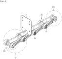
- the conveyor chain composed of unit chains linked together is provided with attachments (see FIG. 4 ) for installing flights at regular intervals.
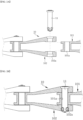
- barrels 101 of one chain and yokes 102 of the other chain among two unit chains to be connected to each other are disposed to face each other (see FIG. 2A ).
- the barrel 101 is placed inside the yoke 102 in a state shown in FIG. 2A , and a steel sleeve-integrated chain pin 11 is inserted into the yoke and the barrel to connect the two unit chains 10 (see FIG. 2B ).
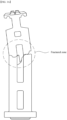
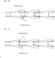
- a conveyor chain having a typical chain link structure is disposed in the sedimentation basin and subjected to tensile force, and the tensile force applied to the chain acts as shear load on the chain pin 11, which does not have a structure capable of distributing the shear load concentrated thereon and thus bears the entire shear load.
- the present invention has been made to solve the aforementioned problems and it is an object of the present invention to improve durability of a non-metallic conveyor chain applied to a sludge removal facility by improving shear strength of the non-metallic conveyor chain through improvement of a chain link structure of the non-metallic conveyor chain.
- the present invention aims at providing a non-metallic conveyor chain with durability improved through increase in shear resistance thereof by allowing shear load borne by a chain pin due to tensile load applied to the chain in a sedimentation basin to be distributed to a barrel and a yoke of the chain surrounding the chain pin, and a sludge removal facility including the same.
- a non-metallic conveyor chain with improved durability for a sludge collector including a plurality of unit chains and chain pins by which the unit chains are linked to each other, wherein each of the unit chains is provided at one side thereof with a barrel and at the other side thereof with a yoke, the barrel of the unit chain is formed on an outer surface thereof with a chain pocket having a groove structure, and the yoke of the unit chain is formed on an inner surface thereof with a chain boss protruding so as to correspond to the chain pocket of the unit chain to which the chain boss is to be linked.
- the chain pocket may include a save rim spaced apart from a pinhole of the barrel and formed in a predetermined region along a circumference of the pinhole, and an opening acting as a passage through which the chain boss is inserted into the chain pocket to be placed therein.
- An inlet width of the opening may be greater than or equal to an outer diameter of the chain boss.
- the chain pocket may further include a guide having a plane guiding movement of the chain boss inserted into the chain pocket through the opening from one side of an inlet of the opening to an inner surface of one side of the save rim, the guide constituting the chain pocket together with the save rim.
- An inner surface of the chain pocket may be formed to have a gradient in a depth direction of the chain pocket such that the chain pocket has a diameter increasing with depth into the chain pocket.
- a non-metallic conveyor chain with improved durability for a sludge collector including a plurality of unit chains and chain pins by which the unit chains are linked to each other, wherein each of the unit chains is provided at one side thereof with a barrel and at the other side thereof with a yoke, the barrel of the unit chain is formed on an outer surface thereof with a chain boss, and the yoke of the unit chain is formed on an inner surface thereof with a chain pocket recessed so as to correspond to the chain boss of the unit chain to which the chain pocket is to be linked.
- a maximum width between chain bosses formed at opposite sides on the outer surface of the barrel may be greater than an inner width of the yoke into which the barrel is inserted.
- a front region of the chain boss in an insertion direction of the barrel may be gradually lowered in a forward direction so as to facilitate insertion of the barrel into the yoke upon assembly of the barrel and the yoke.
- the chain pin may include an SRP chain pin made of steel reinforced plastic (SRP).
- SRP steel reinforced plastic
- a sludge removal facility including: a sedimentation basin into which raw water is introduced; and a sludge collector configured to scrape sludge from a bottom of the sedimentation basin and discharge the sludge from the sedimentation basin, wherein the sludge collector is provided with the non-metallic conveyor chain according to any one of claims 1 to 8 to send scum pushed through operation of flights constituting the sludge collector from a water surface of the sedimentation basin to a trough for discharge.
- the present invention can improve durability of a non-metallic conveyor chain through increase in shear resistance thereof by allowing shear load borne by a chain pin due to tensile load applied to the chain in a sedimentation basin to be distributed to a barrel and a yoke of the chain surrounding the chain pin.
- a chain pocket on an outer surface of the barrel engages with a chain boss on an inner surface of the yoke to reduce shear stress together with the chain pin, thereby improving lifespan of the non-metallic conveyor chain through improvement in durability of the non-metallic conveyor chain.
- the present invention improves durability and lifespan of the non-metallic conveyor chain through improvement of the chain link structure thereof, thereby not only reducing cost loss for replacement and maintenance due to chain fracture occurring in typical conveyor chains, but also contributing to economic improvement in operation of a sludge removal facility by preventing social and economic losses due to treatment failure of raw water in a sedimentation basin.
- FIG. 4 is a perspective view of a link structure of a conveyor chain according to a first embodiment of the present invention
- FIG. 5 is an exploded perspective view of Part A of FIG. 4
- FIG. 6 is a cross-sectional view of Part 'A' of FIG. 4 , showing a chain boss formed on the yoke and inserted into a chain pocket formed on a barrel of the conveyor chain.
- the conveyor chain for a sludge collector includes a plurality of unit chains 10 and chain pins 11 inserted into pinholes 101a, 102a to mediate linkage between the unit chains 10.
- the unit chain 10 is provided at one side thereof with barrels 101 and at the other side thereof with yokes 102, in which each of the barrels 101 of the unit chain 10 is formed on an outer surface thereof with chain pockets CP having a groove structure and each of the yokes 102 of the unit chain 10 is formed on an inner surface thereof with chain bosses CB protruding so as to correspond to the chain pockets CP of the unit chain 10 to which the chain bosses are to be linked.
- each of the chain pockets CP includes a save rim SR spaced apart from a pinhole 101a of the barrel 101 and formed in a predetermined region along a circumference of the pinhole 101a, an opening CPO which acts as a passage through which the chain boss CB is inserted into the chain pocket CP to be placed therein, a guide CPG having a plane guiding movement of the chain boss CB inserted into the chain pocket CP through the opening CPO from one side of an inlet of the opening CPO to an inner surface of one side of the save rim SR.
- the guide CPG includes a vertical surface, thereby constituting the chain pocket CP together with the save rim SR and the opening CPO.
- an inlet width of the opening CPO is greater than or equal to an outer diameter of the chain boss CB.
- the non-metallic conveyor chain according to the first embodiment of the present invention has the following effects.
- the shear load applied to the chain in the sedimentation basin is received by the barrel 101 and the yoke 102 of the chain surrounding the chain pin 11 together, thereby making it possible to improve durability of the conveyor chain through improvement in shear resistance of the non-metallic conveyor chain.
- the chain pockets CP on the outer surface of the barrels 101 engage with the chain bosses CB on the inner surfaces of the yokes 102 to reduce shear stress together with the chain pins 11, thereby improving lifespan of the non-metallic conveyor chain and other facilities including the same through improvement in durability of the non-metallic conveyor chain.
- FIG. 7 and FIG. 8 a second embodiment of the present invention will be described.
- FIG. 7 is an exploded perspective view of a link structure of a conveyor chain according to a second embodiment of the present invention and FIG. 8 is a cross-sectional view of the link structure of the conveyor chain according to the second embodiment of the present invention shown in FIG. 7 .
- the basic structure of the conveyor chain according to the second embodiment is the same as the basic structure of the conveyor chain according to the first embodiment except that a gradient is formed on a matching surface of the chain pocket CP and the chain boss CB.
- the conveyor chain for a sludge collector also includes a plurality of unit chains 10 and chain pins 11 inserted into pinholes 101a, 102a to mediate linkage between the unit chains 10
- the unit chain 10 is provided at one side thereof with barrels 101 and at the other side thereof with yokes 102, in which each of the barrels 101 of the unit chain 10 is formed on an outer surface thereof with chain pockets CP having a groove structure and each of the yokes 102 of the unit chain 10 is formed on an inner surface thereof with chain bosses CB protruding so as to correspond to the chain pockets CP of the unit chain 10 to which the chain bosses are to be linked.
- each of the chain pockets CP includes a save rim SR spaced apart from a pinhole 101a of the barrel 101 and formed in a predetermined region along a circumference of the pinhole 101a, an opening CPO which acts as a passage through which the chain boss CB is inserted into the chain pocket CP to be placed therein, a guide CPG having a plane guiding movement of the chain boss CB inserted into the chain pocket CP through the opening CPO from one side of an inlet of the opening CPO to an inner surface of one side of the save rim SR.
- the guide CPG constitutes the chain pocket CP together with the save rim SR and the opening CPO, in which the guide surface of the guide CPG and the inner surface of the save rim SR are configured to have a gradient.
- an inner surface of the chain pocket CP generally has a diameter gradually increasing from outside of the pocket to inside of the pocket in a depth direction of the pocket.
- the inner surface of the save rim SR and the guide surface of the guide CPG constituting the chain pocket CP form a gradient in the depth direction of the chain pocket CP such that the chain pocket CP has a diameter increasing with depth into the chain pocket CP.
- the chain pocket CP is provided at one side thereof with the guide CPG including the guide surface having a gradient for efficient assembly of the chain boss CB of the yoke 102, which is inserted through the opening CPO corresponding to a region in which the chain pocket CP is not formed.
- the inner surface of the save rim SR and the inner surface of the guide CPG have a gradient such that the chain pocket CP has a gradually increasing area towards a bottom surface of the chain pocket CP, and an outer surface of the chain boss CB has a gradient corresponding thereto.
- the matching surface of the chain boss CB or the chain pocket CP has a gradient, thereby preventing the yoke from spreading.
- the gradient formed in the chain boss CB and the chain pocket CP constitutes a hook CPH, thereby more effectively preventing an existing phenomenon that the chain pin 11 is bent to allow the yoke to spread when the chain is subjected to tensile load.
- each of the chain boss CB and the chain pocket CP has the gradient to form the hook CPH and acts to prevent the yoke 102 from spreading due to interference with axial movement of the chain pin 11.
- the yoke 102 can be effectively prevented from spreading apart, thereby further preventing fracture of the chain.
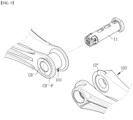
- FIG. 9 is an exploded perspective view of a link structure of a conveyor chain according to a third embodiment of the present invention
- FIG. 10 is a cross-sectional view of the link structure of the conveyor chain according to the third embodiment of the present invention shown in FIG. 9
- FIG. 11 is a plan view of a barrel shown in FIG. 9
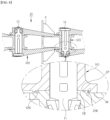
- FIG. 12 is a view illustrating a guide slope range in a chain boss of the barrel shown in FIG. 9 .
- a conveyor chain for a sludge collector includes a plurality of unit chains 10 and chain pins 11 each mediating linkage between the unit chains 10.
- the unit chain 10 is provided at one side thereof with barrels 101 and at the other side thereof with yokes 102, in which each of the barrels 101 of the unit chain 10 is formed on an outer surface thereof with chain bosses CB' and each of the yokes 102 of the unit chain 10 is formed on an inner surface thereof with chain pockets CP' recessed so as to correspond to the chain bosses CB' of the unit chain 10 to which the chain pockets are to be linked.
- a maximum width between the chain bosses CB' formed at opposite sides on the outer surface of the barrel 101 is greater than an inner width of the yoke 102 (that is, a distance between opposite inner surfaces of the yoke) into which the barrel 101 is inserted.
- a front region CB'-F of the chain boss CB' in an insertion direction of the barrel 101 is gradually lowered in a forward direction so as to facilitate insertion of the barrel 101 into the yoke 102 upon assembly of the barrel 101 and the yoke 102.
- the maximum width between the chain bosses CB' formed at the opposite sides on the outer surface of the barrel 101 is greater than the inner width of the yoke 102 into which the barrel 101 is inserted.
- the front region CB'-F of the chain boss CB' in the insertion direction of the barrel 101 is gradually lowered toward a front end thereof, the barrel 101 can be easily inserted into the yoke 102 when the barrel 101 and the yoke 102 are assembled.
- the barrel 101 can be easily inserted into the yoke 102 at the beginning of assembly and, since the maximum width between the chain bosses CB' at the opposite sides on the outer surface of the barrel 101 is greater than the inner width of the yoke 102 into which the barrel 101 is inserted, the chain bosses CB' of the barrel 101 interfere with the yoke 102 during insertion of the barrel 101.
- the yoke 102 which has an elastically deformable structure, is spread to both sides by interference with the chain bosses CB' of the barrel 101, and when the chain bosses CB' of the barrel 101 reach a place at which the chain bosses CB' of the barrel 101 engage with the chain pockets CP' of the yoke 102, the yoke 102 is forced inwardly by elastic resilience, whereby the chain bosses CB' of the barrel 101 are inserted exactly into the chain pockets CP' of the yoke 102.
- the chain bosses CB' of the barrel 101 when assembled, are inserted into the chain pockets CP' of the yoke 102 by resilience of the yoke 102 and an inner wall of each chain pocket CP' is caught by a protrusion formed at a rear end of the chain boss CB' when tensile load is applied to the conveyor chain.
- the fourth embodiment of the present invention modifies the structure of the barrel of the unit chain 10 from a typical integral type to a separable type, and the structure according to the fourth embodiment is applicable to the structures of the unit chains according to the first to third embodiments described above.
- the barrel 101 which is an element constituting a unit chain, is characterized in that a connecting portion connecting left and right sides of the barrel is configured in the form of a separable roller.
- the fourth embodiment of the present invention has the following effects.
- a connecting portion integrally connecting left and right sides of the barrel 101 has a separable roller structure such that the separated roller-shaped connecting portion 1011 can be assembled to and supported on supports 1012, which protrude from left and right inner surfaces of the barrel, when the chain is assembled.
- the roller-shaped connecting portion 1011 is a separable structure in engagement of the chain and the sprocket, the roller-shaped connecting portion 1011 can roll in place in the event of interference with the sprocket and an engagement position of the connecting portion 1011 with respect to the sprocket can be changed by such rolling action of the connecting portion 1011.
- Such a change of the engagement position by rolling of the connecting portion 1011 can prevent side wear of the connecting portion 1011 in engagement of the barrel 101 with the sprocket, thereby reducing load on the chain.
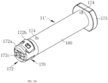
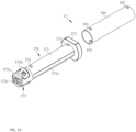
- FIG. 14 is a perspective view of a chain pin made of steel reinforced plastic (SRP) as another embodiment of the chain pin according to the present invention and FIG. 15 is an exploded perspective view of FIG. 14 .
- SRP steel reinforced plastic
- the chain pin may be made of high-strength steel reinforced plastic (SRP).
- SRP high-strength steel reinforced plastic
- a chain pin 11' (hereinafter referred to as "SRP chain pin"), to which high-strength steel reinforced plastic (SRP) technology is applied, refers to a chain pin in which a shaft portion of the chain pin is inserted into a stainless steel pipe, and is applied to the connecting portion in order to allow the unit chains 10 to be regularly connected to each other to form a line.
- SRP chain pin high-strength steel reinforced plastic
- the SRP chain pin 11' includes a plastic pin unit 170 formed of a plastic material and a steel sleeve 180 made of stainless steel and coupled to the plastic pin unit 170.
- the plastic pin unit 170 may be formed of, for example, an engineering plastic material. Such a plastic pin unit 170 includes a shaft portion 171, a jaw portion 172 coupled to one end of the shaft portion 171, and a flange 173 formed at the other end of the shaft portion 171 and having a larger cross-sectional area than the shaft portion 171.
- the shaft portion 171 may be formed with a plurality of through-holes (not shown). Since the plastic pin unit 170 is also formed of a plastic material which weighs significantly less than metal, the plurality of through-holes formed in the shaft portion 171 further reduces the overall weight of the plastic pin unit 170.
- the plastic pin unit 170 can have less strength and wear resistance than a pin unit, the entire shaft portion of which is made of steel, such a disadvantage of the plastic pin unit 170 can be compensated for by the steel sleeve 180 made of stainless steel.
- the jaw portion 172 constitutes one end of the shaft portion 171. After the stainless steel sleeve 180 is press-fitted into the shaft portion 171, the jaw portion 172 may be coupled to one end of the shaft portion 171. However, it should be understood that such a coupling method does not limit the scope of the present invention.
- the SRP chain pin 11' can be molded in other ways.
- the shaft portion 171 may be integrally formed with the steel sleeve 180 through insert-injection molding, with the steel sleeve 180 inserted into a mold, thereby eliminating a separate assembly process of press-fitting the steel sleeve 180 into the shaft portion 171.
- the jaw portion 172 may be injection molded onto one end of the shaft portion 171 simultaneously with injection molding of the shaft portion 171.
- the jaw portion 172 may include a jaw pocket 172a and a plurality of jaw wings 172b slantedly protruding from a circumferential surface of the jaw pocket 172a.
- the plurality of jaw wings 172b may be caught by peripheral edges at one side of pinholes formed in the unit chain 10, whereby the SRP chain pin 11' can be assembled to the unit chain.
- a fix pin 172c may be disposed at a central point of the plurality of jaw wings 172b.
- the flange 173 constitutes the other end of the shaft portion 171. Since the flange 173 has a larger cross-sectional area than the shaft portion 171, the flange 173 serves to prevent the plastic pin unit 170 from falling out of the pinholes formed in the unit chain 10.
- the steel sleeve 180 is integrally formed with the shaft portion 171 of the plastic pin unit 170 through injection molding.
- the steel sleeve 180 is applied to an insert-injection type steel sleeve-integrated chain pin 11 through insert-injection molding in a mold, in which the steel sleeve 180 is integrally molded to an outer wall of the shaft portion 171.
- a plurality of assembly holes 181 is formed in an externally prefabricated steel sleeve 180 and assembly protrusions 174 are formed on the outer wall of the shaft portion 171 to be coupled to the assembly holes 181. Therefore, the insert-injection type SRP chain pin 11' prevents idling of the pin unit 170 and the steel sleeve 180.
- Such an insert-injection type SRP chain pin 11' serves to prevent delamination by repeated buckling loads applied to the non-metallic conveyor chain according to this embodiment.
- the externally prefabricated steel sleeve 180 may also be integrally press-fitted into the shaft 171 of the plastic pin unit 170.
- the present invention can improve durability of a non-metallic conveyor chain applied to a sedimentation basin of a sewage or wastewater treatment system of a sludge removal facility by increasing shear strength of the non-metallic conveyor chain through improvement of a chain link structure of the non-metallic conveyor chain, thereby improving operation efficiency by preventing a phenomenon causing interference with operation of the sewage or wastewater treatment system due to fracture of the conveyor chain, and is applicable not only to water treatment and polluted water purification facilities, but also to various facilities requiring conveyor chains. Accordingly, the present invention has high industrial applicability.
Landscapes
- Engineering & Computer Science (AREA)
- Mechanical Engineering (AREA)
- Chemical & Material Sciences (AREA)
- Chemical Kinetics & Catalysis (AREA)
- General Engineering & Computer Science (AREA)
- Chain Conveyers (AREA)
- Sewage (AREA)
Applications Claiming Priority (2)
| Application Number | Priority Date | Filing Date | Title |
|---|---|---|---|
| KR1020220042295A KR102827066B1 (ko) | 2022-04-05 | 2022-04-05 | 내구성이 향상된 비금속 컨베이어 체인 및 이를 구비한 슬러지 제거설비 |
| PCT/KR2023/001495 WO2023195613A1 (ko) | 2022-04-05 | 2023-02-02 | 내구성이 향상된 비금속 컨베이어 체인 및 이를 구비한 슬러지 제거설비 |
Publications (2)
| Publication Number | Publication Date |
|---|---|
| EP4506281A1 true EP4506281A1 (de) | 2025-02-12 |
| EP4506281A4 EP4506281A4 (de) | 2026-04-08 |
Family
ID=88243025
Family Applications (1)
| Application Number | Title | Priority Date | Filing Date |
|---|---|---|---|
| EP23784841.1A Pending EP4506281A4 (de) | 2022-04-05 | 2023-02-02 | Nichtmetallische förderkette mit verbesserter haltbarkeit und schlammentfernungsanlage damit |
Country Status (6)
| Country | Link |
|---|---|
| US (1) | US20250236467A1 (de) |
| EP (1) | EP4506281A4 (de) |
| JP (1) | JP7849827B2 (de) |
| KR (1) | KR102827066B1 (de) |
| CN (1) | CN119173459A (de) |
| WO (1) | WO2023195613A1 (de) |
Family Cites Families (13)
| Publication number | Priority date | Publication date | Assignee | Title |
|---|---|---|---|---|
| US4050323A (en) * | 1976-01-12 | 1977-09-27 | Anson Thomas I | Pintle-type industrial conveyor chain |
| JP3151414B2 (ja) * | 1997-01-29 | 2001-04-03 | 日本ケーブル・システム株式会社 | チェーン |
| KR20000066012A (ko) | 1999-04-12 | 2000-11-15 | 박계남 | 체인 컨베이어용 비금속 체인 |
| KR20010078409A (ko) * | 2001-07-23 | 2001-08-20 | 오진환 | 체인 컨베이어용 비금속 체인 핀 |
| KR200262312Y1 (ko) * | 2001-10-27 | 2002-03-18 | 태성엔지니어링 주식회사 | 슬러지 수집기의 스컴 수집 장치 |
| KR100496240B1 (ko) * | 2003-01-22 | 2005-06-20 | 주식회사 제이 엠 씨. 엠 | 슬러지수집기에 있어서의 체인링크 연결장치 |
| JP4245186B1 (ja) * | 2007-11-02 | 2009-03-25 | アサヒ機装株式会社 | 汚泥掻き寄せ装置のチェーン装置 |
| JP6359803B2 (ja) * | 2013-03-27 | 2018-07-18 | 株式会社椿本チエイン | チェーン |
| KR101966165B1 (ko) * | 2017-05-24 | 2019-08-13 | (주)태광엔텍 | 체인 플라이트식 슬러지 수집기에 적합한 핀틀 체인 |
| KR101966770B1 (ko) * | 2017-07-05 | 2019-04-19 | 주식회사 링콘테크놀로지 | 비금속 컨베이어 체인 및 그에 적용되는 스틸튜브 일체식 체인핀, 그리고 이를 포함하는 슬러지 수집기 |
| KR102050406B1 (ko) | 2018-02-26 | 2019-12-02 | 주식회사 링콘테크놀로지 | 스틸링 보강 바렐을 구비하는 컨베이어 체인 및 그 제조방법 |
| KR102169694B1 (ko) | 2019-12-26 | 2020-10-23 | 주식회사 링콘테크놀로지 | 보강된 플라이트를 구비한 체인 플라이트 방식의 슬러지 수집기 |
| KR102205545B1 (ko) | 2020-04-20 | 2021-01-20 | 주식회사 링콘테크놀로지 | 슬러지 수집기용 단위체인 및 이의 제조방법 |
-
2022
- 2022-04-05 KR KR1020220042295A patent/KR102827066B1/ko active Active
-
2023
- 2023-02-02 JP JP2024559101A patent/JP7849827B2/ja active Active
- 2023-02-02 CN CN202380037984.8A patent/CN119173459A/zh active Pending
- 2023-02-02 EP EP23784841.1A patent/EP4506281A4/de active Pending
- 2023-02-02 US US18/853,914 patent/US20250236467A1/en active Pending
- 2023-02-02 WO PCT/KR2023/001495 patent/WO2023195613A1/ko not_active Ceased
Also Published As
| Publication number | Publication date |
|---|---|
| KR20230143434A (ko) | 2023-10-12 |
| US20250236467A1 (en) | 2025-07-24 |
| WO2023195613A1 (ko) | 2023-10-12 |
| JP7849827B2 (ja) | 2026-04-22 |
| CN119173459A (zh) | 2024-12-20 |
| JP2025512311A (ja) | 2025-04-17 |
| EP4506281A4 (de) | 2026-04-08 |
| KR102827066B1 (ko) | 2025-06-30 |
Similar Documents
| Publication | Publication Date | Title |
|---|---|---|
| EP0198334B1 (de) | Klärungsanlage für Wasser und Behandlungsanlage für Abwasser | |
| US11123659B2 (en) | Sludge collector | |
| US5165522A (en) | Collector flight attachment link for collector apparatus | |
| EP4506281A1 (de) | Nichtmetallische förderkette mit verbesserter haltbarkeit und schlammentfernungsanlage damit | |
| KR102782525B1 (ko) | 슬러지 수집기용 체인 링크 및 이를 이용하여 연결되는 체인 어셈블리 | |
| HK40113445A (zh) | 具有改进的耐久性的非金属输送链及包含所述非金属输送链的污泥移除设施 | |
| KR20210035999A (ko) | 체인 플라이트식 슬러지 수집기 | |
| US12539473B2 (en) | Roller for chain and scraper assembly | |
| US9751029B2 (en) | Headshaft | |
| KR102397425B1 (ko) | 체인 전동장치 및 이를 사용하는 슬러지 수집장치 | |
| WO2001078861A2 (en) | Wide rectangular clarifiers | |
| KR101966770B1 (ko) | 비금속 컨베이어 체인 및 그에 적용되는 스틸튜브 일체식 체인핀, 그리고 이를 포함하는 슬러지 수집기 | |
| KR102842151B1 (ko) | 슬러지수집기 구동시스템 및 이를 구비한 슬러지 제거설비 | |
| JP2024009247A (ja) | 沈砂池 | |
| JP2007185625A (ja) | 汚泥かき寄せ装置用チェーン及び汚泥かき寄せ装置 | |
| KR100496240B1 (ko) | 슬러지수집기에 있어서의 체인링크 연결장치 | |
| KR200289573Y1 (ko) | 광폭 체인플라이트형 비금속 슬러지수집기 | |
| KR200160419Y1 (ko) | 체인플라이트식 슬러지 수집기의 체인스프로켓 | |
| KR102190000B1 (ko) | 슬러지 수집기용 마모방지형 비금속 아이들 스프라켓 및 이를 포함하는 비금속 체인플라이트식 슬러지 수집기 | |
| KR200311260Y1 (ko) | 슬러지수집기에 있어서의 체인링크 연결장치 | |
| KR101871863B1 (ko) | 체인 플라이트식 슬러지 수집기 | |
| KR20030077237A (ko) | 광폭 체인플라이트형 비금속 슬러지수집기 | |
| AU2015100055A4 (en) | Headshaft | |
| JP2022073980A (ja) | スプロケット、スプロケットの製造方法及び汚泥かき寄せ機 | |
| HK40019718A (en) | Sludge collector |
Legal Events
| Date | Code | Title | Description |
|---|---|---|---|
| STAA | Information on the status of an ep patent application or granted ep patent |
Free format text: STATUS: THE INTERNATIONAL PUBLICATION HAS BEEN MADE |
|
| PUAI | Public reference made under article 153(3) epc to a published international application that has entered the european phase |
Free format text: ORIGINAL CODE: 0009012 |
|
| STAA | Information on the status of an ep patent application or granted ep patent |
Free format text: STATUS: REQUEST FOR EXAMINATION WAS MADE |
|
| 17P | Request for examination filed |
Effective date: 20241022 |
|
| AK | Designated contracting states |
Kind code of ref document: A1 Designated state(s): AL AT BE BG CH CY CZ DE DK EE ES FI FR GB GR HR HU IE IS IT LI LT LU LV MC ME MK MT NL NO PL PT RO RS SE SI SK SM TR |
|
| DAV | Request for validation of the european patent (deleted) | ||
| DAX | Request for extension of the european patent (deleted) | ||
| A4 | Supplementary search report drawn up and despatched |
Effective date: 20260311 |
|
| RIC1 | Information provided on ipc code assigned before grant |
Ipc: B65G 19/20 20060101AFI20260305BHEP Ipc: B65G 19/10 20060101ALI20260305BHEP Ipc: B01D 21/18 20060101ALI20260305BHEP Ipc: F16G 13/06 20060101ALI20260305BHEP Ipc: B01D 21/20 20060101ALI20260305BHEP Ipc: B01D 21/04 20060101ALI20260305BHEP |