EP4502506A1 - Refrigeration cycle device - Google Patents
Refrigeration cycle device Download PDFInfo
- Publication number
- EP4502506A1 EP4502506A1 EP22935158.0A EP22935158A EP4502506A1 EP 4502506 A1 EP4502506 A1 EP 4502506A1 EP 22935158 A EP22935158 A EP 22935158A EP 4502506 A1 EP4502506 A1 EP 4502506A1
- Authority
- EP
- European Patent Office
- Prior art keywords
- water
- nozzles
- pipe
- nozzle
- heat exchanger
- Prior art date
- Legal status (The legal status is an assumption and is not a legal conclusion. Google has not performed a legal analysis and makes no representation as to the accuracy of the status listed.)
- Pending
Links
Images


Classifications
-
- F—MECHANICAL ENGINEERING; LIGHTING; HEATING; WEAPONS; BLASTING
- F25—REFRIGERATION OR COOLING; COMBINED HEATING AND REFRIGERATION SYSTEMS; HEAT PUMP SYSTEMS; MANUFACTURE OR STORAGE OF ICE; LIQUEFACTION SOLIDIFICATION OF GASES
- F25B—REFRIGERATION MACHINES, PLANTS OR SYSTEMS; COMBINED HEATING AND REFRIGERATION SYSTEMS; HEAT PUMP SYSTEMS
- F25B7/00—Compression machines, plants or systems, with cascade operation, i.e. with two or more circuits, the heat from the condenser of one circuit being absorbed by the evaporator of the next circuit
-
- F—MECHANICAL ENGINEERING; LIGHTING; HEATING; WEAPONS; BLASTING
- F25—REFRIGERATION OR COOLING; COMBINED HEATING AND REFRIGERATION SYSTEMS; HEAT PUMP SYSTEMS; MANUFACTURE OR STORAGE OF ICE; LIQUEFACTION SOLIDIFICATION OF GASES
- F25B—REFRIGERATION MACHINES, PLANTS OR SYSTEMS; COMBINED HEATING AND REFRIGERATION SYSTEMS; HEAT PUMP SYSTEMS
- F25B39/00—Evaporators; Condensers
- F25B39/02—Evaporators
-
- F—MECHANICAL ENGINEERING; LIGHTING; HEATING; WEAPONS; BLASTING
- F25—REFRIGERATION OR COOLING; COMBINED HEATING AND REFRIGERATION SYSTEMS; HEAT PUMP SYSTEMS; MANUFACTURE OR STORAGE OF ICE; LIQUEFACTION SOLIDIFICATION OF GASES
- F25B—REFRIGERATION MACHINES, PLANTS OR SYSTEMS; COMBINED HEATING AND REFRIGERATION SYSTEMS; HEAT PUMP SYSTEMS
- F25B39/00—Evaporators; Condensers
- F25B39/04—Condensers
-
- F—MECHANICAL ENGINEERING; LIGHTING; HEATING; WEAPONS; BLASTING
- F28—HEAT EXCHANGE IN GENERAL
- F28D—HEAT-EXCHANGE APPARATUS, NOT PROVIDED FOR IN ANOTHER SUBCLASS, IN WHICH THE HEAT-EXCHANGE MEDIA DO NOT COME INTO DIRECT CONTACT
- F28D5/00—Heat-exchange apparatus having stationary conduit assemblies for one heat-exchange medium only, the media being in contact with different sides of the conduit wall, using the cooling effect of natural or forced evaporation
- F28D5/02—Heat-exchange apparatus having stationary conduit assemblies for one heat-exchange medium only, the media being in contact with different sides of the conduit wall, using the cooling effect of natural or forced evaporation in which the evaporating medium flows in a continuous film or trickles freely over the conduits
-
- F—MECHANICAL ENGINEERING; LIGHTING; HEATING; WEAPONS; BLASTING
- F25—REFRIGERATION OR COOLING; COMBINED HEATING AND REFRIGERATION SYSTEMS; HEAT PUMP SYSTEMS; MANUFACTURE OR STORAGE OF ICE; LIQUEFACTION SOLIDIFICATION OF GASES
- F25B—REFRIGERATION MACHINES, PLANTS OR SYSTEMS; COMBINED HEATING AND REFRIGERATION SYSTEMS; HEAT PUMP SYSTEMS
- F25B2339/00—Details of evaporators; Details of condensers
- F25B2339/04—Details of condensers
-
- F—MECHANICAL ENGINEERING; LIGHTING; HEATING; WEAPONS; BLASTING
- F25—REFRIGERATION OR COOLING; COMBINED HEATING AND REFRIGERATION SYSTEMS; HEAT PUMP SYSTEMS; MANUFACTURE OR STORAGE OF ICE; LIQUEFACTION SOLIDIFICATION OF GASES
- F25B—REFRIGERATION MACHINES, PLANTS OR SYSTEMS; COMBINED HEATING AND REFRIGERATION SYSTEMS; HEAT PUMP SYSTEMS
- F25B2339/00—Details of evaporators; Details of condensers
- F25B2339/04—Details of condensers
- F25B2339/047—Water-cooled condensers
-
- F—MECHANICAL ENGINEERING; LIGHTING; HEATING; WEAPONS; BLASTING
- F25—REFRIGERATION OR COOLING; COMBINED HEATING AND REFRIGERATION SYSTEMS; HEAT PUMP SYSTEMS; MANUFACTURE OR STORAGE OF ICE; LIQUEFACTION SOLIDIFICATION OF GASES
- F25B—REFRIGERATION MACHINES, PLANTS OR SYSTEMS; COMBINED HEATING AND REFRIGERATION SYSTEMS; HEAT PUMP SYSTEMS
- F25B2400/00—Component parts or details not otherwise provided for in this subclass
- F25B2400/06—Several compression cycles arranged in parallel
-
- F—MECHANICAL ENGINEERING; LIGHTING; HEATING; WEAPONS; BLASTING
- F28—HEAT EXCHANGE IN GENERAL
- F28D—HEAT-EXCHANGE APPARATUS, NOT PROVIDED FOR IN ANOTHER SUBCLASS, IN WHICH THE HEAT-EXCHANGE MEDIA DO NOT COME INTO DIRECT CONTACT
- F28D1/00—Heat-exchange apparatus having stationary conduit assemblies for one heat-exchange medium only, the media being in contact with different sides of the conduit wall, in which the other heat-exchange medium is a large body of fluid, e.g. domestic or motor car radiators
- F28D1/02—Heat-exchange apparatus having stationary conduit assemblies for one heat-exchange medium only, the media being in contact with different sides of the conduit wall, in which the other heat-exchange medium is a large body of fluid, e.g. domestic or motor car radiators with heat-exchange conduits immersed in the body of fluid
- F28D1/04—Heat-exchange apparatus having stationary conduit assemblies for one heat-exchange medium only, the media being in contact with different sides of the conduit wall, in which the other heat-exchange medium is a large body of fluid, e.g. domestic or motor car radiators with heat-exchange conduits immersed in the body of fluid with tubular conduits
- F28D1/053—Heat-exchange apparatus having stationary conduit assemblies for one heat-exchange medium only, the media being in contact with different sides of the conduit wall, in which the other heat-exchange medium is a large body of fluid, e.g. domestic or motor car radiators with heat-exchange conduits immersed in the body of fluid with tubular conduits the conduits being straight
- F28D1/0535—Heat-exchange apparatus having stationary conduit assemblies for one heat-exchange medium only, the media being in contact with different sides of the conduit wall, in which the other heat-exchange medium is a large body of fluid, e.g. domestic or motor car radiators with heat-exchange conduits immersed in the body of fluid with tubular conduits the conduits being straight the conduits having a non-circular cross-section
- F28D1/05366—Assemblies of conduits connected to common headers, e.g. core type radiators
- F28D1/05375—Assemblies of conduits connected to common headers, e.g. core type radiators with particular pattern of flow, e.g. change of flow direction
Definitions
- the present disclosure relates to a refrigeration cycle apparatus that sprinkles water on a condenser.
- Patent Literature 1 discloses a spray device including a plurality of spray nozzles provided to sprinkle water on a heat exchanger having plate fins.
- the plurality of spray nozzles are disposed in front of the heat exchanger to spray a mist of water on the heat exchanger during cooling operation during which the heat exchanger serves as a condenser.
- Patent Literature 1 Japanese Patent Publication No. 5880019
- the condenser is a heat exchanger having corrugated fins
- sprinkled water tends to accumulate in valleys of wavy corrugated fins, and the condenser is more likely to hold the water, compared to a heat exchanger having plate fins.
- the amount of water held in the condenser increases, resulting in a resistance against airflow, then performance of the condenser may degrade.
- the present disclosure has been made to overcome the above problems, and it is an object of the present disclosure to provide a refrigeration cycle apparatus that can prevent a condenser from performance degradation caused due to sprinkling of water.
- a refrigeration cycle apparatus includes: a condenser having corrugated fins; and a water supply device configured to sprinkle water on the condenser, wherein the water supply device sprinkles water with a drop diameter of 160 ⁇ m or smaller.
- the water supply device sprinkles water with a drop diameter of 160 ⁇ m or smaller on a condenser having corrugated fins, so that it is possible to prevent an increase in the amount of water held in the condenser, and prevent the condenser from performance degradation.
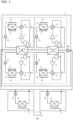
- Fig. 1 is a schematic configuration diagram of a refrigeration cycle apparatus 100 according to Embodiment 1.
- the refrigeration cycle apparatus 100 in the present Embodiment 1 is a heat pump chiller that conditions air by using chilled or heated water.
- the refrigeration cycle apparatus 100 includes a heat source unit 1, indoor units 2, and a controller 3.
- the heat source unit 1 in the present embodiment has four systems of refrigerant circuits. Two systems of refrigerant circuits of them are grouped together to share a single unit of water heat exchanger 60.
- the heat source unit 1 in the present embodiment has two groups, each of which is made up of two systems of refrigerant circuits. Two units of water heat exchangers 60 are connected in series by pipes to cool or heat water that is a heat medium in two stages.
- each system of refrigerant circuit in the heat source unit 1 in the present embodiment is formed by connecting a compressor 11, a four-way valve 12, an outdoor heat exchanger 13, an expansion valve 14, the water heat exchanger 60, and an accumulator 15 by pipes.
- the refrigerant to be used include a single-component refrigerant such as R-22 or R-134a, a near-azeotropic refrigerant mixture such as R-410A or R404A, and a non-azeotropic refrigerant mixture such as R-407C.
- a mixture containing the relatively-low global warming coefficient refrigerant such as CO 2 or propane.
- the compressor 11 compresses suctioned refrigerant and discharges the compressed refrigerant.
- the compressor 11 is driven through a compressor inverter drive device (not illustrated) or other devices. Based on an instruction from the controller 3, the driving frequency of the compressor 11 is optionally changed, and thereby the capacity of the compressor 11 that is the amount of refrigerant to be fed per unit time can be accordingly changed.
- the four-way valve 12 serving as a flow switching device switches between flow directions of refrigerant depending on the operating mode based on the instruction from the controller 3. For example, during cooling operation, the four-way valve 12 changes the flow of refrigerant to such a flow direction that high-temperature high-pressure refrigerant discharged from the compressor 11 flows into the outdoor heat exchanger 13. During heating operation, the four-way valve 12 changes the flow of refrigerant to such a flow direction that high-temperature high-pressure refrigerant discharged from the compressor 11 flows into the water heat exchanger 60.
- the outdoor heat exchanger 13 allows refrigerant to exchange heat with outside air.
- the outdoor heat exchanger 13 serves as an evaporator during water-heating operation (heating operation), and allows low-pressure refrigerant entering from the expansion valve 14 to exchange heat with air to evaporate and gasify the refrigerant.
- the outdoor heat exchanger 13 also serves as a condenser during water-cooling operation (cooling operation), and allows high-pressure refrigerant entering from the compressor 11 to exchange heat with air to condense and liquefy the refrigerant.
- a water supply device 5 is attached to the outdoor heat exchanger 13.
- the water supply device 5 sprinkles water on the outdoor heat exchanger 13 when the outdoor heat exchanger 13 serves as a condenser.
- the outdoor heat exchanger 13 and the water supply device 5 will be described later in detail.
- the outdoor fan 16 delivers air to the outdoor heat exchanger 13 to help exchange heat between refrigerant and the air.
- the outdoor fan 16 is driven through a fan inverter drive device (not illustrated) or other devices. Based on an instruction from the controller 3, the driving frequency is optionally changed, and thereby the airflow volume of the outdoor fan 16 can be accordingly changed. While in Fig. 1 , the outdoor fan 16 is provided in one-to-one correspondence with the outdoor heat exchanger 13, the outdoor heat exchanger 13 and the outdoor fan 16 are not particularly limited to this relationship.
- the water heat exchanger 60 that is a heat medium heat exchanger allows water that is a heat medium to exchange heat with refrigerant.
- the water heat exchanger 60 serves as a flow passage for two systems of refrigerant circuits, and also serves as a flow passage for a heat medium circulation circuit. Therefore, the water heat exchanger 60 is a constituent device of the refrigerant circuit, while being a constituent device of the heat medium circulation circuit.
- the water heat exchanger 60 serves as a condenser during heating operation, and allows refrigerant entering from the compressor 11 to exchange heat with water to condense and liquefy the refrigerant or to condense the refrigerant into a two-phase gas-liquid state, thus to heat the water.
- the water heat exchanger 60 serves as an evaporator during cooling operation, and allows refrigerant entering from the expansion valve 14 to exchange heat with water to evaporate and gasify the refrigerant, thus to cool the water.
- the expansion valve 14 that is an expansion device changes, for example, its opening degree to regulate the pressure of refrigerant that passes through the water heat exchanger 60.
- the expansion valve 14 in the present embodiment is an electronic expansion valve configured to change its opening degree based on an instruction from the controller 3.
- the expansion valve 14 may be a thermostatic expansion valve configured to change its opening degree based on the temperature of refrigerant.
- the accumulator 15 is provided on the suction side of each compressor 11 to reserve surplus refrigerant in the refrigerant circuit.
- a pump 80 is one of the constituent devices of the heat medium circulation circuit.
- the pump 80 suctions water and applies a pressure to the water to feed and circulate the water.
- a pump inverter drive device (not illustrated) optionally changes the driving frequency of the pump 80, and thus can change the capacity of the pump 80.
- the indoor unit 2 delivers conditioned air to an indoor space to be air-conditioned.
- each of the indoor units 2 in the present embodiment includes an indoor heat exchanger 21, an indoor flow-rate regulation device 22, and an indoor fan 23.
- the indoor heat exchanger 21 and the indoor flow-rate regulation device 22 are constituent devices of the heat medium circulation circuit. While Fig. 1 illustrates the refrigeration cycle apparatus 100 having two indoor units 2, the number of indoor units 2 may be equal to one, or equal to or larger than three.
- the indoor flow-rate regulation device 22 is constituted by, for example, a two-way valve whose opening degree (opening area) is controllable.
- the indoor flow-rate regulation device 22 regulates the opening degree to control the flow rate of water flowing into and out from the indoor heat exchanger 21.
- the indoor flow-rate regulation device 22 regulates the amount of water that passes through the indoor heat exchanger 21 based on the temperature of water flowing into the indoor unit 2 and the temperature of water flowing out from the indoor unit 2, and thus allows the indoor heat exchanger 21 to exchange heat in response to the heat quantity depending on an indoor thermal load.
- the indoor flow-rate regulation device 22 can fully close the valve to stop water supply to block the water from flowing into and out from the indoor heat exchanger 21. While in Fig. 1 , the indoor flow-rate regulation device 22 is installed in a pipe extending from the water outflow side of the indoor heat exchanger 21, this is not a limitation. For example, the indoor flow-rate regulation device 22 may be installed on the water inflow side of the indoor heat exchanger 21.
- the indoor heat exchanger 21 is a fin-and-tube heat exchanger configured to exchange heat between water and indoor air in an indoor space supplied from the indoor fan 23.
- the indoor fan 23 generates a flow of air to cause air in the indoor space to pass through the indoor heat exchanger 21 and return to the indoor space.
- the controller 3 controls operation of the refrigeration cycle apparatus 100 in its entirety.
- the controller 3 is constituted by a computer including a memory configured to store data and programs necessary for controlling the operation, and a CPU configured to execute the programs, or is constituted by dedicated hardware such as ASIC or FPGA or by both the computer and the dedicated hardware.
- the controller 3 controls each unit of the refrigeration cycle apparatus 100 based on information detected by a temperature sensor or a pressure sensor included in the refrigeration cycle apparatus 100, and based on an instruction from a remote control (not illustrated).
- the controller 3 controls the driving frequency of the compressor 11, the rotation speed of the outdoor fan 16 and the indoor fan 23, switching of the four-way valve 12, the opening degree of the expansion valve 14, the driving frequency of the pump 80, the opening degree of the indoor flow-rate regulation device 22, sprinkling of water from the water supply device 5, and other operations.
- controller 3 is provided separately from the heat source unit 1 and the indoor units 2 in Fig. 1 , the controller 3 may be provided in the heat source unit 1 or the indoor units 2. It is also allowable that the heat source unit 1 and the indoor units 2 both include their respective controllers 3 that are connected wirelessly or with wires such that the controllers 3 can communicate with each other to transmit and receive various types of data and other information.
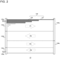
- Fig. 2 is a schematic configuration diagram of the outdoor heat exchanger 13 according to Embodiment 1.
- the outdoor heat exchanger 13 in the present embodiment is a parallel flow heat exchanger (PFC heat exchanger).
- the outdoor heat exchanger 13 includes a heat exchange part 130 made up of a plurality of heat transfer tubes 131 and a plurality of fins 132, first headers 133a, 133b, and 133c, second headers 134a and 134b, and connection pipes 135a and 135b.
- Fig. 2 only partially illustrates the heat transfer tubes 131 and the fins 132, and omits illustrations of their entirety.
- Each of the heat transfer tubes 131 is a flat tube having a plurality of flow passages formed therein.
- the heat transfer tubes 131 are located to extend between the first headers 133a, 133b, and 133c, and the second headers 134a and 134b.
- the heat transfer tubes 131 are spaced apart from each other in a direction perpendicular to the extending direction.
- first direction or “horizontal direction”
- second direction or “vertical direction
- a direction perpendicular to the horizontal direction and the vertical direction is sometimes referred to as "depth direction.”
- Each of the fins 132 is a corrugated fin that is bent into a wavy pattern.
- the fins 132 are located to extend between the first headers 133a, 133b, and 133c, and the second headers 134a and 134b.
- Each of the fins 132 is arranged between two adjacent heat transfer tubes 131 of the plurality of heat transfer tubes 131. The two adjacent heat transfer tubes 131 are connected by the fin 132.
- the first headers 133a, 133b, and 133c are connected to one end of the plurality of heat transfer tubes 131 in their extending direction.
- the second headers 134a and 134b are connected to the other end of the plurality of heat transfer tubes 131 in their extending direction.
- the first headers 133a, 133b, and 133c, and the second headers 134a and 134b have a function of distributing refrigerant flowing into the outdoor heat exchanger 13 to the plurality of heat transfer tubes 131, and a function of merging the flows of refrigerant having passed through the plurality of heat transfer tubes 131 together.
- connection pipe 135a is connected at one end to the first header 133a, while being connected at the other end to the four-way valve 12.
- connection pipe 135b is connected at one end to the first header 133c, while being connected at the other end to the expansion valve 14.
- a plurality of flow passages P1, P2, P3, and P4 are formed in the heat exchange part 130.
- Fig. 2 illustrates four flow passages P1 to P4 in the heat exchange part 130 when the outdoor heat exchanger 13 serves as a condenser.
- refrigerant discharged from the compressor 11 passes through the four-way valve 12 and flows into the first header 133a from the connection pipe 135a.
- the refrigerant flowing into the first header 133a then passes through the flow passage P1 formed by a plurality of heat transfer tubes 131 connected to the first header 133a and flows into the second header 134a.
- the refrigerant flowing into the second header 134a then passes through the flow passage P2 formed by a plurality of heat transfer tubes 131 connected between the second header 134a and the first header 133b and flows into the first header 133b.
- the refrigerant flowing into the first header 133b then passes through the flow passage P3 formed by a plurality of heat transfer tubes 131 connected between the first header 133b and the second header 134b and flows into the second header 134b.
- the refrigerant flowing into the second header 134b then passes through the flow passage P4 formed by a plurality of heat transfer tubes 131 connected between the second header 134b and the first header 133c and flows into the first header 133c.
- the refrigerant flowing into the first header 133c passes through the connection pipe 135b and flows out to the expansion valve 14.
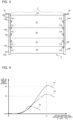
- Fig. 3 is a schematic configuration diagram of the water supply device 5 of the refrigeration cycle apparatus 100 according to Embodiment 1.
- Fig. 3 also illustrates the outdoor heat exchanger 13 for description purposes.
- the water supply device 5 is attached to a housing or the like that holds the outdoor heat exchanger 13.
- the water supply device 5 and the outdoor heat exchanger 13 are spaced apart from each other in the depth direction to prevent a reduction in heat exchange efficiency in the outdoor heat exchanger 13.
- the water supply device 5 includes a first pipe 50a, a second pipe 50b, a connection pipe 52 connected to the first pipe 50a, and a connection pipe 52 connected to the second pipe 50b.
- the first pipe 50a and the second pipe 50b are independent of each other.
- One end of the first pipe 50a and one end of the second pipe 50b are connected to their respective connection pipes 52.
- the connection pipes 52 are connected to water pipes or other pipes. Water entering from the connection pipes 52 is supplied to the first pipe 50a and the second pipe 50b.
- Each of the connection pipes 52 is provided with a valve configured to regulate the flow rate of water.
- the controller 3 controls the valve to control start and stop of water sprinkling from the water supply device 5 and control its water sprinkling amount.
- the first pipe 50a and the second pipe 50b are located opposite to each other.
- the first pipe 50a is located on an outer side relative to one end of the heat exchange part 130 in the horizontal direction, and extends in the vertical direction.
- the second pipe 50b is located on an outer side relative to the other end of the heat exchange part 130 in the horizontal direction, and extends in the vertical direction. Note that in the descriptions below, one end side of the heat exchange part 130 in the horizontal direction is referred to as "first header side,” while the other end side of the heat exchange part 130 in the horizontal direction is referred to as "second header side.”
- the first pipe 50a is provided with a plurality of first nozzles 51a. While in an example in Fig. 3 , the first pipe 50a is provided with five first nozzles 51a, the number of first nozzles 51a may be equal to or smaller than four, or equal to or larger than six.
- Each of the first nozzles 51a is, for example, a hollow conical nozzle that sprays a mist of water at a spray angle of 60°.
- the first nozzles 51a are spaced apart from each other in the vertical direction to sprinkle water on the flow passages P1 to P4 in the heat exchange part 130 from the first header side toward the second header side. In other words, each of the first nozzles 51a sprinkles water from one end side of the outdoor heat exchanger 13 to be directed toward the center of the outdoor heat exchanger 13 in the horizontal direction.
- the second pipe 50b is provided with a plurality of second nozzles 51b. While in the example in Fig. 3 , the second pipe 50b is provided with five second nozzles 51b, the number of second nozzles 51b may be equal to or smaller than four, or equal to or larger than six.
- Each of the second nozzles 51b is, for example, a hollow conical nozzle that sprays a mist of water at a spray angle of 60°.
- the second nozzles 51b are spaced apart from each other in the vertical direction to sprinkle water transversely on the flow passages P1 to P4 in the heat exchange part 130 from the second header side to be directed toward the first header side.
- each of the second nozzles 51b sprinkles water from the other end side of the outdoor heat exchanger 13 to be directed toward the center of the outdoor heat exchanger 13 in the horizontal direction.
- the second nozzles 51b are located opposite to the first nozzles 51a.
- Each of the second nozzles 51b, and its corresponding first nozzle 51a are positioned at the same height in the vertical direction.
- the water supply device 5 in the present embodiment sprinkles water with a drop diameter of 160 ⁇ m or smaller, and preferably 110 ⁇ m or smaller, from each of the first and second nozzles 51a and 51b. Further, the water sprinkling amount per unit area through each of the first and second nozzles 51a and 51b of the water supply device 5 is 1.2 ⁇ 0.2 L/(min ⁇ m 2 ), in other words, equal to or more than 1.0 L/(min ⁇ m 2 ) and equal to or less than 1.4 L/(min ⁇ m 2 ).
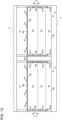
- Fig. 4 is a graph illustrating the relationship between the water sprinkling amount per unit area for a heat exchanger having corrugated fins to each drop diameter, and COP improvement rate.
- the graph of Fig. 4 was obtained through experiments in sprinkling the heat exchanger having corrugated fins with different amounts of water to each drop diameter.
- the COP improvement rate in Fig. 4 refers to a rate of improvement to a COP obtained when the heat exchanger is not sprinkled with water.
- a solid line R1 in the graph of Fig. 4 shows the COP improvement rate where the drop diameter is 110 ⁇ m.
- a dash-dot line R2 in the graph of Fig. 4 shows the COP improvement rate where the drop diameter is 160 ⁇ m.
- a dash-double-dot line R3 in the graph of Fig. 4 shows the COP improvement rate where the drop diameter is 200 ⁇ m. Note that the heat exchanger used for the experiments has a fin pitch of 1 to 2 mm.
- the COP improvement rate where the drop diameter is equal to or smaller than 160 ⁇ m is higher than the COP improvement rate where the drop diameter is equal to or smaller than 200 ⁇ m.
- the COP improvement rate increases when the water sprinkling amount per unit area is close to 1.2 L/(min ⁇ M 2 ). That is, it is understood from Fig. 4 that the COP improvement rate can be increased (to, for example, 30% or higher), where the drop diameter is equal to or smaller than 160 ⁇ m and where the water sprinkling amount per unit area is 1.2 ⁇ 0.2 L/(min ⁇ m 2 ).
- the COP improvement rate can be maximized to 50% or higher, where the drop diameter is 110 ⁇ m and where the water sprinkling amount per unit area is 1.2 L/(min ⁇ m 2 ).
- the total flow rate is 2.00 L/min and the water sprinkling amount per unit area is 1.12 L/(min ⁇ m 2 ).
- the heat exchange part 130 is supposed to have a height of 1.22 meters and a width of 1.47 meters.
- a lower limit of the drop diameter of water to be sprinkled from each nozzle of the water supply device 5 may be set at, for example, 60 ⁇ m. That is, the drop diameter of water to be sprinkled from each nozzle of the water supply device 5 may be set equal to or larger than 60 ⁇ m and equal to or smaller than 160 ⁇ m.
- the reasons for this are that assuming that the drop diameter of water to be sprinkled from each nozzle of the water supply device 5 is smaller than 60 ⁇ m, many nozzles are needed to achieve a target water sprinkling amount per unit area, which leads to a limitation on the arrangement of the nozzles or a cost increase. Assuming that the drop diameter is smaller than 60 ⁇ m, drops of the sprinkled water are more likely to be affected by external airflow which may prevent the drops from striking the outdoor heat exchanger 13.
- the outdoor heat exchanger 13 serving as a condenser is sprinkled with water by the water supply device 5, and the drop diameter of water to be sprinkled from each nozzle of the water supply device 5 is set equal to or smaller than 160 ⁇ m. It is thus possible to prevent an increase in the amount of water held in the outdoor heat exchanger 13. As a result, it is possible to prevent the outdoor heat exchanger 13 from performance degradation, and thus achieve COP improvement by means of sprinkling water.
- the water sprinkling amount per unit area from the water supply device 5 is set to 1.2 ⁇ 0.2 L/(min ⁇ m 2 ), so that it is possible to achieve further COP improvement.
- the above effects are significant particularly when the fins 132 have a fin pitch of 1 to 2 mm.
- Embodiment 2 is described below. Embodiment 2 is different in configuration of a water supply device 5A from Embodiment 1.
- the configuration of the refrigeration cycle apparatus 100 in Embodiment 2, other than the water supply device 5A, is identical to Embodiment 1.
- Fig. 5 is a side view of the heat source unit 1 of the refrigeration cycle apparatus 100 according to Embodiment 2.
- the heat source unit 1 is a top-flow outdoor unit with the outdoor fan 16 located above the outdoor heat exchanger 13.
- an airflow velocity distribution of air entering the outdoor heat exchanger 13 is generated as illustrated by the arrows in Fig. 5 . Specifically, as a flow of air enters closer to the top of the outdoor heat exchanger 13, the airflow velocity increases, while as the flow of air enters closer to the bottom thereof, the airflow velocity decreases.
- the relationship of airflow velocity of air that enters each of the flow passages P1, P2, P3, and P4 in the heat exchange part 130 of the outdoor heat exchanger 13 is expressed as "airflow velocity in P1 > P2 > P3 > P4.”
- the outdoor heat exchangers 13 are oriented with an inclination relative to the vertical direction, and the heat source unit 1 has a Y-shape in side view, however, it is allowable that the outdoor heat exchangers 13 are oriented without being inclined relative to the vertical direction.
- Fig. 6 illustrates a temperature distribution in the outdoor heat exchanger 13 according to Embodiment 2 when the outdoor heat exchanger 13 serves as a condenser.
- the temperature distribution shows a higher temperature in a region of the heat exchange part 130 closer to the connection pipe 135a that is an inlet of refrigerant, while showing a lower temperature in a region of the heat exchange part 130 closer to the connection pipe 135b that is an outlet of the refrigerant. That is, the temperature decreases from the upstream side to the downstream side in the flow direction of refrigerant in the heat exchange part 130.
- Fig. 6 illustrates a temperature distribution in the outdoor heat exchanger 13 according to Embodiment 2 when the outdoor heat exchanger 13 serves as a condenser.
- the temperature distribution shows a higher temperature in a region of the heat exchange part 130 closer to the connection pipe 135a that is an inlet of refrigerant, while showing a lower temperature in a region of the heat exchange part 130 closer to the connection pipe 135b that is an
- the flow passage P1 has a high temperature (at, for example, 80 to 100 degrees C)
- the flow passage P2 has an intermediate temperature (at, for example, 40 to 50 degrees C)
- the flow passages P3 and P4 have a low temperature (at, for example, 30 to 40 degrees C).
- the outdoor heat exchanger 13 has a non-uniform airflow velocity distribution and a non-uniform temperature distribution.
- the water supply device 5 sprinkles water evenly on the heat exchange part 130, there are variations in cooling effects produced by sprinkling water. This results in a reduction of the condensation-capacity improvement effect and a reduction in the water sprinkling efficiency. Therefore, the configuration of the water supply device 5A in the present embodiment takes into account the airflow velocity distribution and the temperature distribution in the outdoor heat exchanger 13.
- Fig. 7 is a schematic configuration diagram of the water supply device 5A of the refrigeration cycle apparatus 100 according to Embodiment 2.
- Fig. 7 also illustrates the outdoor heat exchanger 13 for description purposes.
- the water supply device 5A is attached to the housing or the like that holds the outdoor heat exchanger 13.
- the water supply device 5A and the outdoor heat exchanger 13 are spaced apart from each other in the depth direction to prevent a reduction in heat exchange efficiency in the outdoor heat exchanger 13.
- the water supply device 5A includes the first pipe 50a, the second pipe 50b, a third pipe 50C, and the connection pipe 52.
- the first pipe 50a and the second pipe 50b are located opposite to each other below the third pipe 50c.
- the third pipe 50c is connected at one end to the first pipe 50a, while being connected at the other end to the second pipe 50b.
- the second pipe 50b and the third pipe 50c are connected to the connection pipe 52.
- the connection pipe 52 is connected to a water pipe or other pipe. Water entering from the connection pipe 52 is supplied to the second pipe 50b, the third pipe 50c, and the first pipe 50a.
- the connection pipe 52 is provided with a valve configured to regulate the flow rate of water.
- the controller 3 controls the valve to control start and stop of water sprinkling from the water supply device 5A and control its water sprinkling amount.
- the first pipe 50a is located on an outer side relative to one end of the heat exchange part 130 in the horizontal direction, and extends in the vertical direction.
- the second pipe 50b is located on an outer side relative to the other end of the heat exchange part 130 in the horizontal direction, and extends in the vertical direction.
- the first pipe 50a is provided with a plurality of first nozzles.
- the first pipe 50a is provided with three first nozzles 51a1, 51a2, and 51a3.
- Each of the first nozzles 51a1, 51a2, and 51a3 is, for example, a hollow conical nozzle that sprays a mist of water at a spray angle of 60°.
- the first nozzles 51a1, 51a2, and 51a3 are spaced apart from each other in the vertical direction.
- the first nozzle 51a1 is provided to sprinkle water mainly on the flow passage P2.
- the first nozzle 51a2 is provided to sprinkle water mainly on the flow passage P3.
- the first nozzle 51a3 is provided to sprinkle water mainly on the flow passage P4.
- Each of the first nozzles 51a1, 51a2, and 51a3 sprinkles water from the first header side to be directed toward the second header side, that is, from one end side of the outdoor heat exchanger 13 to be directed toward the center of the outdoor heat exchanger 13 in the horizontal direction.
- the water sprinkling amount from each of the first nozzles 51a1, 51a2, and 51a3 is 0.24 L/min, and the drop diameter is equal to or smaller than 160 ⁇ m that is, for example, 110 ⁇ m.
- the second pipe 50b is provided with a plurality of second nozzles.
- the second pipe 50b is provided with three second nozzles 51b1, 51b2, and 51b3.
- Each of the second nozzles 51b1, 51b2, and 51b3 is, for example, a hollow conical nozzle that sprays a mist of water at a spray angle of 60°.
- the second nozzles 51b1, 51b2, and 51b3 are spaced apart from each other in the vertical direction.
- the second nozzles 51b1, 51b2, and 51b3 are located opposite to the first nozzles 51a1, 51a2, and 51a3, respectively.
- Each of the second nozzles 51b1, 51b2, and 51b3, and its corresponding first nozzle 51a1, 51a2, and 51a3 are positioned at the same height in the vertical direction.
- the second nozzle 51b1 is provided to sprinkle water mainly on the flow passage P2.
- the second nozzle 51b2 is provided to sprinkle water mainly on the flow passage P3.
- the second nozzle 51b3 is provided to sprinkle water mainly on the flow passage P4.
- Each of the second nozzles 51b1, 51b2, and 51b3 sprinkles water from the second header side to be directed toward the first header side, that is, from the other end side of the outdoor heat exchanger 13 to be directed toward the center of the outdoor heat exchanger 13 in the horizontal direction.
- the water sprinkling amount from each of the second nozzles 51b is 0.24 L/min, and the drop diameter is equal to or smaller than 160 ⁇ m that is, for example, 110 ⁇ m.
- the third pipe 50c is located to extend in the horizontal direction along the lower end of the flow passage P1 in the heat exchange part 130.
- the third pipe 50c is provided with a plurality of third nozzles 51c.
- the third pipe 50c is provided with four third nozzles 51c.
- Each of the third nozzles 51c is, for example, a hollow conical nozzle that sprays a mist of water at a spray angle of 60°.
- the third nozzles 51c are spaced apart from each other in the horizontal direction.
- Each of the third nozzles 51c sprinkles water to upside of the flow passage P1 located in an upper portion of the heat exchange part 130 to direct the water from the lower side of the flow passage P1 toward the upper side thereof.
- the flow passage P1 of the heat exchange part 130 is sprinkled with water from the four third nozzles 51c on the third pipe 50c.
- the water sprinkling amount from each of the third nozzles 51c is 0.13 L/min, and the drop diameter is equal to or smaller than 160 ⁇ m that is, for example, 110 ⁇ m.
- the total water sprinkling amount from the water supply device 5A is 1.96 L/min and the water sprinkling amount per unit area is 1.09 L/(min ⁇ m 2 ).
- FIG. 8 is an explanatory diagram describing the installation angle of the third nozzle 51c on the third pipe 50c according to Embodiment 2.
- Fig. 8 schematically illustrates the third nozzle 51c and the outdoor heat exchanger 13 when the outdoor heat exchanger 13 is viewed from the side (when viewed in the horizontal direction).
- the third nozzle 51c sprinkles water on the flow passage P1 through which airflow passes at the highest velocity.
- the third nozzle 51c sprinkles water to upside of the heat exchange part 130 of the outdoor heat exchanger 13.
- the third nozzle 51c is installed to be inclined at an angle ⁇ 1 relative to the vertical direction such that the third nozzle 51c is oriented toward the outdoor heat exchanger 13.
- the angle ⁇ 1 is, for example 45° to 70°, at which water sprayed from the third nozzles 51c is sprinkled over the entirety of the flow passage P1 of the heat exchange part 130, but not beyond the upper end of the heat exchange part 130.
- the plurality of third nozzles 51c provided on the third pipe 50c are all installed at the same angle.
- Fig. 9 is an explanatory diagram describing the installation angle of the first nozzle 51a1 on the first pipe 50a and the second nozzle 51b1 on the second pipe 50b according to Embodiment 2.
- Fig. 9 schematically illustrates the first nozzle 51a1 and the second nozzle 51b1, and the outdoor heat exchanger 13 when the outdoor heat exchanger 13 is viewed from the top (viewed in the vertical direction).
- the first nozzle 51a1 and the second nozzle 51b1 sprinkle water on the flow passage P2 through which airflow passes at the second highest velocity. As illustrated in Fig.
- the first nozzle 51a1 and the second nozzle 51b1 are installed to be inclined at an angle ⁇ 2 relative to the horizontal direction such that the first nozzle 51a1 and the second nozzle 51b1 are oriented away from the outdoor heat exchanger 13.
- the angle ⁇ 2 is, for example 10° to 20°, at which water sprinkled from the first nozzle 51a1 and the second nozzle 51b1 located at opposite ends of the heat exchange part 130 reaches the center of the heat exchange part 130 with respect to the airflow velocity.
- Fig. 10 is an explanatory diagram describing the installation angle of the first nozzle 51a2 on the first pipe 50a and the second nozzle 51b2 on the second pipe 50b according to Embodiment 2.
- Fig. 10 schematically illustrates the first nozzle 51a2 and the second nozzle 51b2, and the outdoor heat exchanger 13 when the outdoor heat exchanger 13 is viewed from the top (viewed in the vertical direction).
- the first nozzle 51a2 and the second nozzle 51b2 sprinkle water on the flow passage P3 through which airflow passes at the third highest velocity. As illustrated in Fig.
- the first nozzle 51a2 and the second nozzle 51b2 are installed to be inclined at an angle ⁇ 3 relative to the horizontal direction such that the first nozzle 51a2 and the second nozzle 51b2 are oriented away from the outdoor heat exchanger 13.
- the angle ⁇ 3 is, for example 7° to 17°, at which water sprinkled from the first nozzle 51a2 and the second nozzle 51b2 located at opposite ends of the heat exchange part 130 reaches the center of the heat exchange part 130 with respect to the airflow velocity.
- Fig. 11 is an explanatory diagram describing the installation angle of the first nozzle 51a3 on the first pipe 50a and the second nozzle 51b3 on the second pipe 50b according to Embodiment 2.
- Fig. 11 schematically illustrates the first nozzle 51a3 and the second nozzle 51b3, and the outdoor heat exchanger 13 when the outdoor heat exchanger 13 is viewed from the top (viewed in the vertical direction).
- the first nozzle 51a3 and the second nozzle 51b3 sprinkle water on the flow passage P4 through which airflow passes at the lowest velocity. As illustrated in Fig.
- the first nozzle 51a3 and the second nozzle 51b3 are installed to be inclined at an angle ⁇ 4 relative to the horizontal direction such that the first nozzle 51a3 and the second nozzle 51b3 are oriented away from the outdoor heat exchanger 13.
- the angle ⁇ 4 is, for example 0° to 10°, at which water sprinkled from the first nozzle 51a3 and the second nozzle 51b3 located at opposite ends of the heat exchange part 130 reaches the center of the heat exchange part 130 with respect to the airflow velocity.
- the first nozzles 51a1 to 51a3 and the second nozzles 51b1 to 51b3 that sprinkle water from opposite ends of the heat exchange part 130 in the horizontal direction are installed at the angles ⁇ 2 to ⁇ 4 that are set differently depending on the airflow velocity.
- a nozzle that sprinkles water on a high-airflow-velocity region is inclined relative to the horizontal direction at an angle that is set lager than the inclination angle of a nozzle that sprinkles water on a high-airflow-velocity region, such that the sprinkled water reaches the center of the heat exchange part 130.
- the third nozzles 51c are provided on the third pipe 50c extending in the horizontal direction, and are installed to be inclined upward at the angle ⁇ 1. This makes it possible to sprinkle water over the entirety of the flow passage P1 through which airflow passes at the highest velocity.
- the angles ⁇ 2 to ⁇ 4 of the first nozzles 51a1 to 51a3 and the second nozzles 51b1 to 51b3 that sprinkle water transversely from opposite ends of the heat exchange part 130 are set differently depending on the airflow velocity. This makes it possible to sprinkle water over the entirety of the flow passages P2 to P4 of the heat exchange part 130.
- the number of nozzles provided on the third pipe 50c to sprinkle water on the flow passage P1 having a relatively high temperature in the heat exchange part 130 is larger than the number of nozzles provided on the first pipe 50a and is also larger than the number of nozzles provided on the second pipe 50b.
- the water sprinkling amount per unit area for the flow passage P1 having a relatively high temperature in the heat exchange part 130 can be increased more than the water sprinkling amount per unit area for the flow passages P2 to P4 having a relatively low temperature.
- water is sprinkled over the entirety of the outdoor heat exchanger 13 serving as a condenser, and the water sprinkling amount per unit area for the high-temperature region is increased, so that the condensation capacity of the outdoor heat exchanger 13 improves and accordingly the COP improves in the refrigeration cycle apparatus 100 in its entirety.
- water is sprinkled over the entirety of the outdoor heat exchanger 13 serving as a condenser, and the water sprinkling amount per unit area for the low-temperature region of the outdoor heat exchanger 13 is decreased, so that waste of water can be reduced, and the water sprinkling efficiency improves.
- the same effects as those achieved in Embodiment 1 can also be obtained.
- the arrangement of the nozzles, the number of nozzles, and the angles of the nozzles in the water supply device 5A are set as described in the present embodiment, so that it is possible for the outdoor heat exchanger 13 serving as a condenser to prevent a reduction of the condensation-capacity improvement effect, and a reduction in the water sprinkling efficiency, and thus to improve the COP.
- Heat source units 1 of the refrigeration cycle apparatus 100 may be connected together and disposed outdoors.
- Fig. 12 illustrates an example of the arrangement of the heat source units 1 connected together. As illustrated in Fig. 12 , the heat source units 1 of the refrigeration cycle apparatus 100 may be connected together and arranged in the depth direction.
- Fig. 12 illustrates four heat source units 1 connected together in the depth direction.
- a portion of each of the heat source units 1, which is located on the inward side of the outdoor heat exchangers 13, that is, the horizontally central portion of the heat source unit 1, is less affected by external airflow illustrated by the arrows in Fig. 12 . Accordingly, the water evaporation rate is decreased.
- a water supply device 5B in the present embodiment has a configuration to set different drop diameters and different water sprinkling amounts depending on the influence of external airflow.
- Fig. 13 is a schematic configuration diagram of water supply devices 5B according to Embodiment 3.
- Fig. 13 illustrates two water supply devices 5B that sprinkle water respectively on two outdoor heat exchangers 13 of four outdoor heat exchangers 13 included in the heat source unit 1, in which the two outdoor heat exchangers 13 are arranged side by side in the horizontal direction.
- These two water supply devices 5B are connected together by a connection pipe 52a.
- the connection pipe 52a is connected to a water pipe or other pipe. Water entering from the connection pipe 52a is supplied to the second pipes 50b, the third pipes 50c, and the first pipes 50a of the two water supply devices 5B.
- the connection pipe 52 is provided with a valve configured to regulate the flow rate of water.
- the controller 3 controls the valve to control start and stop of water sprinkling from the water supply devices 5B and control their water sprinkling amount.
- each of the water supply devices 5B includes the first pipe 50a, the second pipe 50b, and the third pipe 50c.
- the two water supply devices 5B are attached to a housing 6 of the heat source unit 1 such that the second pipes 50b are positioned on the inward side where the influence of external airflow is insignificant.
- the configuration of the first pipe 50a and the plurality of first nozzles 51a1, 51a2, and 51a3, and the configuration of the third pipe 50c and the plurality of third nozzles 51c in the present embodiment are identical to those in Embodiment 2.
- the second pipe 50b is located on an outer side relative to the other end of the heat exchange part 130 in the horizontal direction, and extends in the vertical direction.
- the second pipe 50b is provided with a plurality of second nozzles.
- the second pipe 50b is provided with three second nozzles 51b11, 51b12, and 51b13.
- Each of the second nozzles 51b11, 51b12, and 51b13 is, for example, a hollow conical nozzle that sprays a mist of water at a spray angle of 60°.
- the second nozzles 51b11, 51b12, and 51b13 are spaced apart from each other in the vertical direction.
- the second nozzles 51b11, 51b12, and 51b13 are located opposite to the first nozzles 51a1, 51a2, and 51a3, respectively. Each of the second nozzles 51b11, 51b12, and 51b13, and its corresponding first nozzle 51a1, 51a2, and 51a3 are positioned at the same height in the vertical direction.
- the second nozzle 51b1 is provided to sprinkle water mainly on the flow passage P2.
- the second nozzle 51b2 is provided to sprinkle water mainly on the flow passage P3.
- the second nozzle 51b3 is provided to sprinkle water mainly on the flow passage P4.
- Each of the second nozzles 51b1, 51b2, and 51b3 sprinkles water from the other end side of the outdoor heat exchanger 13 to be directed toward the center of the outdoor heat exchanger 13 in the horizontal direction.
- the water sprinkling amount from each of the second nozzles 51b11, 51b12, and 51b13 in the present embodiment is 0.10 L/min, and the drop diameter is equal to or smaller than 75 ⁇ m.
- the drop diameter of water to be sprinkled from, and the water sprinkling amount from, each of the second nozzles 51b11, 51b12, and 51b13 located on the inward side are set smaller than the drop diameter of water to be sprinkled from, and the water sprinkling amount from, each of the first nozzles 51a1, 51a2, and 51a3 located on the outward side.
- the angle ⁇ 2 of the second nozzle 51b11 relative to the horizontal direction is, for example, 10° to 20°.
- the angle ⁇ 3 of the second nozzle 51b12 relative to the horizontal direction is, for example, 7° to 17°.
- the angle ⁇ 4 of the second nozzle 51b13 relative to the horizontal direction is, for example, 0° to 10°.
- the same effects as those achieved in Embodiment 1 can also be obtained.
- the drop diameter of water to be sprinkled from each of the nozzles located at such a position that the influence of external airflow is insignificant is set relatively small enough to help the drops of water to easily evaporate, thereby to improve the water sprinkling efficiency.
- the refrigeration cycle apparatus 100 has been described as being a heat pump chiller.
- the refrigeration cycle apparatus 100 may be a device dedicated to cooling that is not provided with a cooling-heating switchable device, or may be a cooling refrigerating machine for a refrigeration storage or a direct-expansion air-conditioning apparatus.
- the refrigeration cycle apparatus 100 is the device dedicated to cooling or the refrigerating machine, the four-way valve 12 is omitted, the outdoor heat exchanger 13 serves as a condenser, and the indoor heat exchanger 21 serves as an evaporator.
- the number of nozzles, their arrangement, and angles, as well as the water sprinkling amount and drop diameter of water to be sprinkled from the nozzles in Embodiment 1 to 3 are merely examples, and can be optionally changed.
- the angles of the nozzles may set differently depending on the airflow velocity distribution, or the water sprinkling amounts may be set differently depending on the temperature distribution.
- the angles of any of or all of the first to third nozzles may be set at 0°.
- the third pipe 50c is located to extend in the horizontal direction along the lower end of the flow passage P1 of the heat exchange part 130.
- the third pipe 50c may be located above or below the lower end of the flow passage P1 of the heat exchange part 130, provided that the third nozzles 51c are at such a position as to sprinkle water on a high-airflow-velocity region and a high-temperature region of the heat exchange part 130.
- the heat source unit 1 has four systems of refrigerant circuits, this is not a limitation.
- the heat source unit 1 may have three or less systems of refrigerant circuits or five or more systems of refrigerant circuits.
- the outdoor heat exchanger 13 has been described as having the four flow passages P1 to P4, the number of flow passages in the outdoor heat exchanger 13 may be equal to or smaller than three, or equal to or larger than five.
Landscapes
- Engineering & Computer Science (AREA)
- Physics & Mathematics (AREA)
- Thermal Sciences (AREA)
- Mechanical Engineering (AREA)
- General Engineering & Computer Science (AREA)
- Other Air-Conditioning Systems (AREA)
Abstract
Description
- The present disclosure relates to a refrigeration cycle apparatus that sprinkles water on a condenser.
- A refrigeration cycle apparatus has been known as sprinkling water on a condenser included in an outdoor unit when the outside air temperature is high, and using heat of water vaporization to cool the condenser, thereby to improve the refrigerant condensation capacity. For example,
Patent Literature 1 discloses a spray device including a plurality of spray nozzles provided to sprinkle water on a heat exchanger having plate fins. InPatent Literature 1, the plurality of spray nozzles are disposed in front of the heat exchanger to spray a mist of water on the heat exchanger during cooling operation during which the heat exchanger serves as a condenser. - Patent Literature 1:
Japanese Patent Publication No. 5880019 - In a case where the condenser is a heat exchanger having corrugated fins, sprinkled water tends to accumulate in valleys of wavy corrugated fins, and the condenser is more likely to hold the water, compared to a heat exchanger having plate fins. When the amount of water held in the condenser increases, resulting in a resistance against airflow, then performance of the condenser may degrade.
- The present disclosure has been made to overcome the above problems, and it is an object of the present disclosure to provide a refrigeration cycle apparatus that can prevent a condenser from performance degradation caused due to sprinkling of water. Solution to Problem
- A refrigeration cycle apparatus according to an embodiment of the present disclosure includes: a condenser having corrugated fins; and a water supply device configured to sprinkle water on the condenser, wherein the water supply device sprinkles water with a drop diameter of 160 µm or smaller.
- In the refrigeration cycle apparatus of the embodiment of the present disclosure, the water supply device sprinkles water with a drop diameter of 160 µm or smaller on a condenser having corrugated fins, so that it is possible to prevent an increase in the amount of water held in the condenser, and prevent the condenser from performance degradation.
-
- [
Fig. 1] Fig. 1 is a schematic configuration diagram of a refrigeration cycle apparatus according toEmbodiment 1. - [
Fig. 2] Fig. 2 is a schematic configuration diagram of an outdoor heat exchanger according toEmbodiment 1. - [
Fig. 3] Fig. 3 is a schematic configuration diagram of a water supply device of the refrigeration cycle apparatus according toEmbodiment 1. - [
Fig. 4] Fig. 4 is a graph illustrating the relationship between the water sprinkling amount per unit area for a heat exchanger having corrugated fins to each drop diameter, and the COP improvement rate. - [
Fig. 5] Fig. 5 is a side view of a heat source unit of the refrigeration cycle apparatus according toEmbodiment 2. - [
Fig. 6] Fig. 6 illustrates a temperature distribution in an outdoor heat exchanger according to Embodiment 2 when the outdoor heat exchanger serves as a condenser. - [
Fig. 7] Fig. 7 is a schematic configuration diagram of the water supply device of the refrigeration cycle apparatus according toEmbodiment 2. - [
Fig. 8] Fig. 8 is an explanatory diagram describing the installation angle of a third nozzle on a third pipe according toEmbodiment 2. - [
Fig. 9] Fig. 9 is an explanatory diagram describing the installation angle of a first nozzle on a first pipe and a second nozzle on a second pipe according toEmbodiment 2. - [
Fig. 10] Fig. 10 is an explanatory diagram describing the installation angle of a first nozzle on the first pipe and a second nozzle on the second pipe according toEmbodiment 2. - [
Fig. 11] Fig. 11 is an explanatory diagram describing the installation angle of a first nozzle on the first pipe and a second nozzle on the second pipe according toEmbodiment 2. - [
Fig. 12] Fig. 12 illustrates an example of the arrangement of heat source units connected together. - [
Fig. 13] Fig. 13 is a schematic configuration diagram of water supply devices according toEmbodiment 3. - Hereinafter, embodiments will be described with reference to the drawings. Note that in the drawings below, the same reference signs denote the same or equivalent components, which are common throughout the entire specification. Further, the forms of the constituent elements described throughout the entire specification are merely examples, and do not intend to limit the constituent elements to the forms described in the specification. Furthermore, the relationship of sizes of the components in the drawings described below may differ from that of actual ones.
-
Fig. 1 is a schematic configuration diagram of arefrigeration cycle apparatus 100 according toEmbodiment 1. Therefrigeration cycle apparatus 100 in thepresent Embodiment 1 is a heat pump chiller that conditions air by using chilled or heated water. As illustrated inFig. 1 , therefrigeration cycle apparatus 100 includes aheat source unit 1,indoor units 2, and acontroller 3. Theheat source unit 1 in the present embodiment has four systems of refrigerant circuits. Two systems of refrigerant circuits of them are grouped together to share a single unit ofwater heat exchanger 60. Theheat source unit 1 in the present embodiment has two groups, each of which is made up of two systems of refrigerant circuits. Two units ofwater heat exchangers 60 are connected in series by pipes to cool or heat water that is a heat medium in two stages. - As illustrated in
Fig. 1 , each system of refrigerant circuit in theheat source unit 1 in the present embodiment is formed by connecting acompressor 11, a four-way valve 12, anoutdoor heat exchanger 13, anexpansion valve 14, thewater heat exchanger 60, and anaccumulator 15 by pipes. Examples of the refrigerant to be used include a single-component refrigerant such as R-22 or R-134a, a near-azeotropic refrigerant mixture such as R-410A or R404A, and a non-azeotropic refrigerant mixture such as R-407C. Examples of the refrigerant to be used further include a relatively-low global warming coefficient refrigerant containing a double bond in its chemical formula, such as CF3CF=CH2, a mixture containing the relatively-low global warming coefficient refrigerant, and a natural refrigerant such as CO2 or propane. - The
compressor 11 compresses suctioned refrigerant and discharges the compressed refrigerant. Thecompressor 11 is driven through a compressor inverter drive device (not illustrated) or other devices. Based on an instruction from thecontroller 3, the driving frequency of thecompressor 11 is optionally changed, and thereby the capacity of thecompressor 11 that is the amount of refrigerant to be fed per unit time can be accordingly changed. - The four-
way valve 12 serving as a flow switching device switches between flow directions of refrigerant depending on the operating mode based on the instruction from thecontroller 3. For example, during cooling operation, the four-way valve 12 changes the flow of refrigerant to such a flow direction that high-temperature high-pressure refrigerant discharged from thecompressor 11 flows into theoutdoor heat exchanger 13. During heating operation, the four-way valve 12 changes the flow of refrigerant to such a flow direction that high-temperature high-pressure refrigerant discharged from thecompressor 11 flows into thewater heat exchanger 60. - The
outdoor heat exchanger 13 allows refrigerant to exchange heat with outside air. Theoutdoor heat exchanger 13 serves as an evaporator during water-heating operation (heating operation), and allows low-pressure refrigerant entering from theexpansion valve 14 to exchange heat with air to evaporate and gasify the refrigerant. Theoutdoor heat exchanger 13 also serves as a condenser during water-cooling operation (cooling operation), and allows high-pressure refrigerant entering from thecompressor 11 to exchange heat with air to condense and liquefy the refrigerant. - A
water supply device 5 is attached to theoutdoor heat exchanger 13. Thewater supply device 5 sprinkles water on theoutdoor heat exchanger 13 when theoutdoor heat exchanger 13 serves as a condenser. Theoutdoor heat exchanger 13 and thewater supply device 5 will be described later in detail. - The
outdoor fan 16 delivers air to theoutdoor heat exchanger 13 to help exchange heat between refrigerant and the air. Theoutdoor fan 16 is driven through a fan inverter drive device (not illustrated) or other devices. Based on an instruction from thecontroller 3, the driving frequency is optionally changed, and thereby the airflow volume of theoutdoor fan 16 can be accordingly changed. While inFig. 1 , theoutdoor fan 16 is provided in one-to-one correspondence with theoutdoor heat exchanger 13, theoutdoor heat exchanger 13 and theoutdoor fan 16 are not particularly limited to this relationship. - The
water heat exchanger 60 that is a heat medium heat exchanger allows water that is a heat medium to exchange heat with refrigerant. Thewater heat exchanger 60 serves as a flow passage for two systems of refrigerant circuits, and also serves as a flow passage for a heat medium circulation circuit. Therefore, thewater heat exchanger 60 is a constituent device of the refrigerant circuit, while being a constituent device of the heat medium circulation circuit. For example, thewater heat exchanger 60 serves as a condenser during heating operation, and allows refrigerant entering from thecompressor 11 to exchange heat with water to condense and liquefy the refrigerant or to condense the refrigerant into a two-phase gas-liquid state, thus to heat the water. In contrast, thewater heat exchanger 60 serves as an evaporator during cooling operation, and allows refrigerant entering from theexpansion valve 14 to exchange heat with water to evaporate and gasify the refrigerant, thus to cool the water. - The
expansion valve 14 that is an expansion device changes, for example, its opening degree to regulate the pressure of refrigerant that passes through thewater heat exchanger 60. Theexpansion valve 14 in the present embodiment is an electronic expansion valve configured to change its opening degree based on an instruction from thecontroller 3. However, this is not a limitation. For example, theexpansion valve 14 may be a thermostatic expansion valve configured to change its opening degree based on the temperature of refrigerant. - The
accumulator 15 is provided on the suction side of eachcompressor 11 to reserve surplus refrigerant in the refrigerant circuit. - A
pump 80 is one of the constituent devices of the heat medium circulation circuit. In the heat medium circulation circuit, thepump 80 suctions water and applies a pressure to the water to feed and circulate the water. Based on an instruction from thecontroller 3, a pump inverter drive device (not illustrated) optionally changes the driving frequency of thepump 80, and thus can change the capacity of thepump 80. - The
indoor unit 2 delivers conditioned air to an indoor space to be air-conditioned. As illustrated inFig. 1 , each of theindoor units 2 in the present embodiment includes anindoor heat exchanger 21, an indoor flow-rate regulation device 22, and anindoor fan 23. Theindoor heat exchanger 21 and the indoor flow-rate regulation device 22 are constituent devices of the heat medium circulation circuit. WhileFig. 1 illustrates therefrigeration cycle apparatus 100 having twoindoor units 2, the number ofindoor units 2 may be equal to one, or equal to or larger than three. - The indoor flow-
rate regulation device 22 is constituted by, for example, a two-way valve whose opening degree (opening area) is controllable. The indoor flow-rate regulation device 22 regulates the opening degree to control the flow rate of water flowing into and out from theindoor heat exchanger 21. The indoor flow-rate regulation device 22 regulates the amount of water that passes through theindoor heat exchanger 21 based on the temperature of water flowing into theindoor unit 2 and the temperature of water flowing out from theindoor unit 2, and thus allows theindoor heat exchanger 21 to exchange heat in response to the heat quantity depending on an indoor thermal load. In a case where theindoor heat exchanger 21 does not need to exchange heat with a thermal load during operation stop, thermostat off, or the like, the indoor flow-rate regulation device 22 can fully close the valve to stop water supply to block the water from flowing into and out from theindoor heat exchanger 21. While inFig. 1 , the indoor flow-rate regulation device 22 is installed in a pipe extending from the water outflow side of theindoor heat exchanger 21, this is not a limitation. For example, the indoor flow-rate regulation device 22 may be installed on the water inflow side of theindoor heat exchanger 21. - The
indoor heat exchanger 21 is a fin-and-tube heat exchanger configured to exchange heat between water and indoor air in an indoor space supplied from theindoor fan 23. During cooling operation, water that is cooler than air passes through heat transfer tubes of theindoor heat exchanger 21, so that the indoor space is cooled. In contrast, during heating operation, water that is warmer than air passes through the heat transfer tubes of theindoor heat exchanger 21, so that the indoor space is heated. Theindoor fan 23 generates a flow of air to cause air in the indoor space to pass through theindoor heat exchanger 21 and return to the indoor space. - The
controller 3 controls operation of therefrigeration cycle apparatus 100 in its entirety. Thecontroller 3 is constituted by a computer including a memory configured to store data and programs necessary for controlling the operation, and a CPU configured to execute the programs, or is constituted by dedicated hardware such as ASIC or FPGA or by both the computer and the dedicated hardware. Thecontroller 3 controls each unit of therefrigeration cycle apparatus 100 based on information detected by a temperature sensor or a pressure sensor included in therefrigeration cycle apparatus 100, and based on an instruction from a remote control (not illustrated). Specifically, thecontroller 3 controls the driving frequency of thecompressor 11, the rotation speed of theoutdoor fan 16 and theindoor fan 23, switching of the four-way valve 12, the opening degree of theexpansion valve 14, the driving frequency of thepump 80, the opening degree of the indoor flow-rate regulation device 22, sprinkling of water from thewater supply device 5, and other operations. - Note that while the
controller 3 is provided separately from theheat source unit 1 and theindoor units 2 inFig. 1 , thecontroller 3 may be provided in theheat source unit 1 or theindoor units 2. It is also allowable that theheat source unit 1 and theindoor units 2 both include theirrespective controllers 3 that are connected wirelessly or with wires such that thecontrollers 3 can communicate with each other to transmit and receive various types of data and other information. - Next, the configuration of the
outdoor heat exchanger 13 in the present embodiment is described.Fig. 2 is a schematic configuration diagram of theoutdoor heat exchanger 13 according toEmbodiment 1. Theoutdoor heat exchanger 13 in the present embodiment is a parallel flow heat exchanger (PFC heat exchanger). Theoutdoor heat exchanger 13 includes aheat exchange part 130 made up of a plurality ofheat transfer tubes 131 and a plurality offins 132,first headers second headers connection pipes Fig. 2 only partially illustrates theheat transfer tubes 131 and thefins 132, and omits illustrations of their entirety. - Each of the
heat transfer tubes 131 is a flat tube having a plurality of flow passages formed therein. Theheat transfer tubes 131 are located to extend between thefirst headers second headers heat transfer tubes 131 are spaced apart from each other in a direction perpendicular to the extending direction. Note that in the descriptions below, the extending direction of each of theheat transfer tubes 131 is sometimes referred to as "first direction" or "horizontal direction," and the direction perpendicular to the extending direction of each of theheat transfer tubes 131 is sometimes referred to as "second direction" or "vertical direction." A direction perpendicular to the horizontal direction and the vertical direction is sometimes referred to as "depth direction." - Each of the
fins 132 is a corrugated fin that is bent into a wavy pattern. Thefins 132 are located to extend between thefirst headers second headers fins 132 is arranged between two adjacentheat transfer tubes 131 of the plurality ofheat transfer tubes 131. The two adjacentheat transfer tubes 131 are connected by thefin 132. - The
first headers heat transfer tubes 131 in their extending direction. Thesecond headers heat transfer tubes 131 in their extending direction. Thefirst headers second headers outdoor heat exchanger 13 to the plurality ofheat transfer tubes 131, and a function of merging the flows of refrigerant having passed through the plurality ofheat transfer tubes 131 together. - The
connection pipe 135a is connected at one end to thefirst header 133a, while being connected at the other end to the four-way valve 12. Theconnection pipe 135b is connected at one end to thefirst header 133c, while being connected at the other end to theexpansion valve 14. - In the above configuration of the
outdoor heat exchanger 13 in the present embodiment, a plurality of flow passages P1, P2, P3, and P4 are formed in theheat exchange part 130.Fig. 2 illustrates four flow passages P1 to P4 in theheat exchange part 130 when theoutdoor heat exchanger 13 serves as a condenser. As illustrated inFig. 2 , when theoutdoor heat exchanger 13 serves as a condenser, refrigerant discharged from thecompressor 11 passes through the four-way valve 12 and flows into thefirst header 133a from theconnection pipe 135a. The refrigerant flowing into thefirst header 133a then passes through the flow passage P1 formed by a plurality ofheat transfer tubes 131 connected to thefirst header 133a and flows into thesecond header 134a. - The refrigerant flowing into the
second header 134a then passes through the flow passage P2 formed by a plurality ofheat transfer tubes 131 connected between thesecond header 134a and thefirst header 133b and flows into thefirst header 133b. The refrigerant flowing into thefirst header 133b then passes through the flow passage P3 formed by a plurality ofheat transfer tubes 131 connected between thefirst header 133b and thesecond header 134b and flows into thesecond header 134b. The refrigerant flowing into thesecond header 134b then passes through the flow passage P4 formed by a plurality ofheat transfer tubes 131 connected between thesecond header 134b and thefirst header 133c and flows into thefirst header 133c. The refrigerant flowing into thefirst header 133c passes through theconnection pipe 135b and flows out to theexpansion valve 14. -
Fig. 3 is a schematic configuration diagram of thewater supply device 5 of therefrigeration cycle apparatus 100 according toEmbodiment 1.Fig. 3 also illustrates theoutdoor heat exchanger 13 for description purposes. Thewater supply device 5 is attached to a housing or the like that holds theoutdoor heat exchanger 13. Thewater supply device 5 and theoutdoor heat exchanger 13 are spaced apart from each other in the depth direction to prevent a reduction in heat exchange efficiency in theoutdoor heat exchanger 13. - As illustrated in
Fig. 3 , thewater supply device 5 includes afirst pipe 50a, asecond pipe 50b, aconnection pipe 52 connected to thefirst pipe 50a, and aconnection pipe 52 connected to thesecond pipe 50b. Thefirst pipe 50a and thesecond pipe 50b are independent of each other. One end of thefirst pipe 50a and one end of thesecond pipe 50b are connected to theirrespective connection pipes 52. Theconnection pipes 52 are connected to water pipes or other pipes. Water entering from theconnection pipes 52 is supplied to thefirst pipe 50a and thesecond pipe 50b. Each of theconnection pipes 52 is provided with a valve configured to regulate the flow rate of water. Thecontroller 3 controls the valve to control start and stop of water sprinkling from thewater supply device 5 and control its water sprinkling amount. - The
first pipe 50a and thesecond pipe 50b are located opposite to each other. Thefirst pipe 50a is located on an outer side relative to one end of theheat exchange part 130 in the horizontal direction, and extends in the vertical direction. Thesecond pipe 50b is located on an outer side relative to the other end of theheat exchange part 130 in the horizontal direction, and extends in the vertical direction. Note that in the descriptions below, one end side of theheat exchange part 130 in the horizontal direction is referred to as "first header side," while the other end side of theheat exchange part 130 in the horizontal direction is referred to as "second header side." - The
first pipe 50a is provided with a plurality offirst nozzles 51a. While in an example inFig. 3 , thefirst pipe 50a is provided with fivefirst nozzles 51a, the number offirst nozzles 51a may be equal to or smaller than four, or equal to or larger than six. Each of thefirst nozzles 51a is, for example, a hollow conical nozzle that sprays a mist of water at a spray angle of 60°. Thefirst nozzles 51a are spaced apart from each other in the vertical direction to sprinkle water on the flow passages P1 to P4 in theheat exchange part 130 from the first header side toward the second header side. In other words, each of thefirst nozzles 51a sprinkles water from one end side of theoutdoor heat exchanger 13 to be directed toward the center of theoutdoor heat exchanger 13 in the horizontal direction. - The
second pipe 50b is provided with a plurality ofsecond nozzles 51b. While in the example inFig. 3 , thesecond pipe 50b is provided with fivesecond nozzles 51b, the number ofsecond nozzles 51b may be equal to or smaller than four, or equal to or larger than six. Each of thesecond nozzles 51b is, for example, a hollow conical nozzle that sprays a mist of water at a spray angle of 60°. Thesecond nozzles 51b are spaced apart from each other in the vertical direction to sprinkle water transversely on the flow passages P1 to P4 in theheat exchange part 130 from the second header side to be directed toward the first header side. In other words, each of thesecond nozzles 51b sprinkles water from the other end side of theoutdoor heat exchanger 13 to be directed toward the center of theoutdoor heat exchanger 13 in the horizontal direction. Thesecond nozzles 51b are located opposite to thefirst nozzles 51a. Each of thesecond nozzles 51b, and its correspondingfirst nozzle 51a are positioned at the same height in the vertical direction. - The
water supply device 5 in the present embodiment sprinkles water with a drop diameter of 160 µm or smaller, and preferably 110 µm or smaller, from each of the first andsecond nozzles second nozzles water supply device 5 is 1.2±0.2 L/(min·m2), in other words, equal to or more than 1.0 L/(min·m2) and equal to or less than 1.4 L/(min·m2). -
Fig. 4 is a graph illustrating the relationship between the water sprinkling amount per unit area for a heat exchanger having corrugated fins to each drop diameter, and COP improvement rate. The graph ofFig. 4 was obtained through experiments in sprinkling the heat exchanger having corrugated fins with different amounts of water to each drop diameter. The COP improvement rate inFig. 4 refers to a rate of improvement to a COP obtained when the heat exchanger is not sprinkled with water. A solid line R1 in the graph ofFig. 4 shows the COP improvement rate where the drop diameter is 110 µm. A dash-dot line R2 in the graph ofFig. 4 shows the COP improvement rate where the drop diameter is 160 µm. A dash-double-dot line R3 in the graph ofFig. 4 shows the COP improvement rate where the drop diameter is 200 µm. Note that the heat exchanger used for the experiments has a fin pitch of 1 to 2 mm. - As illustrated in
Fig. 4 , the COP improvement rate where the drop diameter is equal to or smaller than 160 µm is higher than the COP improvement rate where the drop diameter is equal to or smaller than 200 µm. Where the drop diameter is equal to or smaller than 160 µm, the COP improvement rate increases when the water sprinkling amount per unit area is close to 1.2 L/(min·M2). That is, it is understood fromFig. 4 that the COP improvement rate can be increased (to, for example, 30% or higher), where the drop diameter is equal to or smaller than 160 µm and where the water sprinkling amount per unit area is 1.2±0.2 L/(min·m2). Particularly, the COP improvement rate can be maximized to 50% or higher, where the drop diameter is 110 µm and where the water sprinkling amount per unit area is 1.2 L/(min·m2). - In the
water supply device 5 described inFig. 3 , where the amount of water sprinkling from each of the first andsecond nozzles heat exchange part 130 is supposed to have a height of 1.22 meters and a width of 1.47 meters. - A lower limit of the drop diameter of water to be sprinkled from each nozzle of the
water supply device 5 may be set at, for example, 60 µm. That is, the drop diameter of water to be sprinkled from each nozzle of thewater supply device 5 may be set equal to or larger than 60 µm and equal to or smaller than 160 µm. The reasons for this are that assuming that the drop diameter of water to be sprinkled from each nozzle of thewater supply device 5 is smaller than 60 µm, many nozzles are needed to achieve a target water sprinkling amount per unit area, which leads to a limitation on the arrangement of the nozzles or a cost increase. Assuming that the drop diameter is smaller than 60 µm, drops of the sprinkled water are more likely to be affected by external airflow which may prevent the drops from striking theoutdoor heat exchanger 13. - As described above, in the present embodiment, the
outdoor heat exchanger 13 serving as a condenser is sprinkled with water by thewater supply device 5, and the drop diameter of water to be sprinkled from each nozzle of thewater supply device 5 is set equal to or smaller than 160 µm. It is thus possible to prevent an increase in the amount of water held in theoutdoor heat exchanger 13. As a result, it is possible to prevent theoutdoor heat exchanger 13 from performance degradation, and thus achieve COP improvement by means of sprinkling water. The water sprinkling amount per unit area from thewater supply device 5 is set to 1.2±0.2 L/(min·m2), so that it is possible to achieve further COP improvement. The above effects are significant particularly when thefins 132 have a fin pitch of 1 to 2 mm. -
Embodiment 2 is described below.Embodiment 2 is different in configuration of awater supply device 5A fromEmbodiment 1. The configuration of therefrigeration cycle apparatus 100 inEmbodiment 2, other than thewater supply device 5A, is identical toEmbodiment 1. -
Fig. 5 is a side view of theheat source unit 1 of therefrigeration cycle apparatus 100 according toEmbodiment 2. As illustrated inFig. 5 , theheat source unit 1 is a top-flow outdoor unit with theoutdoor fan 16 located above theoutdoor heat exchanger 13. In a case where theheat source unit 1 is a top-flow outdoor unit, an airflow velocity distribution of air entering theoutdoor heat exchanger 13 is generated as illustrated by the arrows inFig. 5 . Specifically, as a flow of air enters closer to the top of theoutdoor heat exchanger 13, the airflow velocity increases, while as the flow of air enters closer to the bottom thereof, the airflow velocity decreases. That is, the relationship of airflow velocity of air that enters each of the flow passages P1, P2, P3, and P4 in theheat exchange part 130 of theoutdoor heat exchanger 13 is expressed as "airflow velocity in P1 > P2 > P3 > P4." Note that in the example inFig. 5 , theoutdoor heat exchangers 13 are oriented with an inclination relative to the vertical direction, and theheat source unit 1 has a Y-shape in side view, however, it is allowable that theoutdoor heat exchangers 13 are oriented without being inclined relative to the vertical direction. -
Fig. 6 illustrates a temperature distribution in theoutdoor heat exchanger 13 according toEmbodiment 2 when theoutdoor heat exchanger 13 serves as a condenser. As illustrated inFig. 6 , it is understood that when theoutdoor heat exchanger 13 serves as a condenser, the temperature distribution shows a higher temperature in a region of theheat exchange part 130 closer to theconnection pipe 135a that is an inlet of refrigerant, while showing a lower temperature in a region of theheat exchange part 130 closer to theconnection pipe 135b that is an outlet of the refrigerant. That is, the temperature decreases from the upstream side to the downstream side in the flow direction of refrigerant in theheat exchange part 130. For example, as illustrated inFig. 6 , the flow passage P1 has a high temperature (at, for example, 80 to 100 degrees C), the flow passage P2 has an intermediate temperature (at, for example, 40 to 50 degrees C), and the flow passages P3 and P4 have a low temperature (at, for example, 30 to 40 degrees C). - As illustrated in
Figs. 5 and 6 , theoutdoor heat exchanger 13 has a non-uniform airflow velocity distribution and a non-uniform temperature distribution. Thus, assuming that thewater supply device 5 sprinkles water evenly on theheat exchange part 130, there are variations in cooling effects produced by sprinkling water. This results in a reduction of the condensation-capacity improvement effect and a reduction in the water sprinkling efficiency. Therefore, the configuration of thewater supply device 5A in the present embodiment takes into account the airflow velocity distribution and the temperature distribution in theoutdoor heat exchanger 13. -
Fig. 7 is a schematic configuration diagram of thewater supply device 5A of therefrigeration cycle apparatus 100 according toEmbodiment 2.Fig. 7 also illustrates theoutdoor heat exchanger 13 for description purposes. Thewater supply device 5A is attached to the housing or the like that holds theoutdoor heat exchanger 13. Thewater supply device 5A and theoutdoor heat exchanger 13 are spaced apart from each other in the depth direction to prevent a reduction in heat exchange efficiency in theoutdoor heat exchanger 13. - As illustrated in
Fig. 7 , thewater supply device 5A includes thefirst pipe 50a, thesecond pipe 50b, a third pipe 50C, and theconnection pipe 52. Thefirst pipe 50a and thesecond pipe 50b are located opposite to each other below thethird pipe 50c. Thethird pipe 50c is connected at one end to thefirst pipe 50a, while being connected at the other end to thesecond pipe 50b. - The
second pipe 50b and thethird pipe 50c are connected to theconnection pipe 52. Theconnection pipe 52 is connected to a water pipe or other pipe. Water entering from theconnection pipe 52 is supplied to thesecond pipe 50b, thethird pipe 50c, and thefirst pipe 50a. Theconnection pipe 52 is provided with a valve configured to regulate the flow rate of water. Thecontroller 3 controls the valve to control start and stop of water sprinkling from thewater supply device 5A and control its water sprinkling amount. - The
first pipe 50a is located on an outer side relative to one end of theheat exchange part 130 in the horizontal direction, and extends in the vertical direction. Thesecond pipe 50b is located on an outer side relative to the other end of theheat exchange part 130 in the horizontal direction, and extends in the vertical direction. - The
first pipe 50a is provided with a plurality of first nozzles. In an example inFig. 7 , thefirst pipe 50a is provided with three first nozzles 51a1, 51a2, and 51a3. Each of the first nozzles 51a1, 51a2, and 51a3 is, for example, a hollow conical nozzle that sprays a mist of water at a spray angle of 60°. The first nozzles 51a1, 51a2, and 51a3 are spaced apart from each other in the vertical direction. The first nozzle 51a1 is provided to sprinkle water mainly on the flow passage P2. The first nozzle 51a2 is provided to sprinkle water mainly on the flow passage P3. The first nozzle 51a3 is provided to sprinkle water mainly on the flow passage P4. Each of the first nozzles 51a1, 51a2, and 51a3 sprinkles water from the first header side to be directed toward the second header side, that is, from one end side of theoutdoor heat exchanger 13 to be directed toward the center of theoutdoor heat exchanger 13 in the horizontal direction. As an example, the water sprinkling amount from each of the first nozzles 51a1, 51a2, and 51a3 is 0.24 L/min, and the drop diameter is equal to or smaller than 160 µm that is, for example, 110 µm. - The
second pipe 50b is provided with a plurality of second nozzles. In an example inFig. 4 , thesecond pipe 50b is provided with three second nozzles 51b1, 51b2, and 51b3. Each of the second nozzles 51b1, 51b2, and 51b3 is, for example, a hollow conical nozzle that sprays a mist of water at a spray angle of 60°. The second nozzles 51b1, 51b2, and 51b3 are spaced apart from each other in the vertical direction. The second nozzles 51b1, 51b2, and 51b3 are located opposite to the first nozzles 51a1, 51a2, and 51a3, respectively. Each of the second nozzles 51b1, 51b2, and 51b3, and its corresponding first nozzle 51a1, 51a2, and 51a3 are positioned at the same height in the vertical direction. The second nozzle 51b1 is provided to sprinkle water mainly on the flow passage P2. The second nozzle 51b2 is provided to sprinkle water mainly on the flow passage P3. The second nozzle 51b3 is provided to sprinkle water mainly on the flow passage P4. Each of the second nozzles 51b1, 51b2, and 51b3 sprinkles water from the second header side to be directed toward the first header side, that is, from the other end side of theoutdoor heat exchanger 13 to be directed toward the center of theoutdoor heat exchanger 13 in the horizontal direction. As an example, the water sprinkling amount from each of thesecond nozzles 51b is 0.24 L/min, and the drop diameter is equal to or smaller than 160 µm that is, for example, 110 µm. - The
third pipe 50c is located to extend in the horizontal direction along the lower end of the flow passage P1 in theheat exchange part 130. Thethird pipe 50c is provided with a plurality ofthird nozzles 51c. In the example inFig. 7 , thethird pipe 50c is provided with fourthird nozzles 51c. Each of thethird nozzles 51c is, for example, a hollow conical nozzle that sprays a mist of water at a spray angle of 60°. Thethird nozzles 51c are spaced apart from each other in the horizontal direction. Each of thethird nozzles 51c sprinkles water to upside of the flow passage P1 located in an upper portion of theheat exchange part 130 to direct the water from the lower side of the flow passage P1 toward the upper side thereof. That is, the flow passage P1 of theheat exchange part 130 is sprinkled with water from the fourthird nozzles 51c on thethird pipe 50c. As an example, the water sprinkling amount from each of thethird nozzles 51c is 0.13 L/min, and the drop diameter is equal to or smaller than 160 µm that is, for example, 110 µm. - In the present embodiment, where the
heat exchange part 130 has a height of 1.22 meters and a width of 1.47 meters, then the total water sprinkling amount from thewater supply device 5A is 1.96 L/min and the water sprinkling amount per unit area is 1.09 L/(min·m2). - Next, the angle of each nozzle relative to the
outdoor heat exchanger 13 is described.Fig. 8 is an explanatory diagram describing the installation angle of thethird nozzle 51c on thethird pipe 50c according toEmbodiment 2.Fig. 8 schematically illustrates thethird nozzle 51c and theoutdoor heat exchanger 13 when theoutdoor heat exchanger 13 is viewed from the side (when viewed in the horizontal direction). Thethird nozzle 51c sprinkles water on the flow passage P1 through which airflow passes at the highest velocity. As illustrated inFig. 8 , thethird nozzle 51c sprinkles water to upside of theheat exchange part 130 of theoutdoor heat exchanger 13. Thethird nozzle 51c is installed to be inclined at an angle α1 relative to the vertical direction such that thethird nozzle 51c is oriented toward theoutdoor heat exchanger 13. The angle α1 is, for example 45° to 70°, at which water sprayed from thethird nozzles 51c is sprinkled over the entirety of the flow passage P1 of theheat exchange part 130, but not beyond the upper end of theheat exchange part 130. The plurality ofthird nozzles 51c provided on thethird pipe 50c are all installed at the same angle. -
Fig. 9 is an explanatory diagram describing the installation angle of the first nozzle 51a1 on thefirst pipe 50a and the second nozzle 51b1 on thesecond pipe 50b according toEmbodiment 2.Fig. 9 schematically illustrates the first nozzle 51a1 and the second nozzle 51b1, and theoutdoor heat exchanger 13 when theoutdoor heat exchanger 13 is viewed from the top (viewed in the vertical direction). The first nozzle 51a1 and the second nozzle 51b1 sprinkle water on the flow passage P2 through which airflow passes at the second highest velocity. As illustrated inFig. 9 , the first nozzle 51a1 and the second nozzle 51b1 are installed to be inclined at an angle α2 relative to the horizontal direction such that the first nozzle 51a1 and the second nozzle 51b1 are oriented away from theoutdoor heat exchanger 13. The angle α2 is, for example 10° to 20°, at which water sprinkled from the first nozzle 51a1 and the second nozzle 51b1 located at opposite ends of theheat exchange part 130 reaches the center of theheat exchange part 130 with respect to the airflow velocity. -
Fig. 10 is an explanatory diagram describing the installation angle of the first nozzle 51a2 on thefirst pipe 50a and the second nozzle 51b2 on thesecond pipe 50b according toEmbodiment 2.Fig. 10 schematically illustrates the first nozzle 51a2 and the second nozzle 51b2, and theoutdoor heat exchanger 13 when theoutdoor heat exchanger 13 is viewed from the top (viewed in the vertical direction). The first nozzle 51a2 and the second nozzle 51b2 sprinkle water on the flow passage P3 through which airflow passes at the third highest velocity. As illustrated inFig. 10 , the first nozzle 51a2 and the second nozzle 51b2 are installed to be inclined at an angle α3 relative to the horizontal direction such that the first nozzle 51a2 and the second nozzle 51b2 are oriented away from theoutdoor heat exchanger 13. The angle α3 is, for example 7° to 17°, at which water sprinkled from the first nozzle 51a2 and the second nozzle 51b2 located at opposite ends of theheat exchange part 130 reaches the center of theheat exchange part 130 with respect to the airflow velocity. -
Fig. 11 is an explanatory diagram describing the installation angle of the first nozzle 51a3 on thefirst pipe 50a and the second nozzle 51b3 on thesecond pipe 50b according toEmbodiment 2.Fig. 11 schematically illustrates the first nozzle 51a3 and the second nozzle 51b3, and theoutdoor heat exchanger 13 when theoutdoor heat exchanger 13 is viewed from the top (viewed in the vertical direction). The first nozzle 51a3 and the second nozzle 51b3 sprinkle water on the flow passage P4 through which airflow passes at the lowest velocity. As illustrated inFig. 11 , the first nozzle 51a3 and the second nozzle 51b3 are installed to be inclined at an angle α4 relative to the horizontal direction such that the first nozzle 51a3 and the second nozzle 51b3 are oriented away from theoutdoor heat exchanger 13. The angle α4 is, for example 0° to 10°, at which water sprinkled from the first nozzle 51a3 and the second nozzle 51b3 located at opposite ends of theheat exchange part 130 reaches the center of theheat exchange part 130 with respect to the airflow velocity. - As illustrated in
Figs. 9 to 11 , the first nozzles 51a1 to 51a3 and the second nozzles 51b1 to 51b3 that sprinkle water from opposite ends of theheat exchange part 130 in the horizontal direction are installed at the angles α2 to α4 that are set differently depending on the airflow velocity. Specifically, a nozzle that sprinkles water on a high-airflow-velocity region is inclined relative to the horizontal direction at an angle that is set lager than the inclination angle of a nozzle that sprinkles water on a high-airflow-velocity region, such that the sprinkled water reaches the center of theheat exchange part 130. - As described above, the
third nozzles 51c are provided on thethird pipe 50c extending in the horizontal direction, and are installed to be inclined upward at the angle α1. This makes it possible to sprinkle water over the entirety of the flow passage P1 through which airflow passes at the highest velocity. The angles α2 to α4 of the first nozzles 51a1 to 51a3 and the second nozzles 51b1 to 51b3 that sprinkle water transversely from opposite ends of theheat exchange part 130 are set differently depending on the airflow velocity. This makes it possible to sprinkle water over the entirety of the flow passages P2 to P4 of theheat exchange part 130. - In the
water supply device 5A in the present embodiment, the number of nozzles provided on thethird pipe 50c to sprinkle water on the flow passage P1 having a relatively high temperature in theheat exchange part 130 is larger than the number of nozzles provided on thefirst pipe 50a and is also larger than the number of nozzles provided on thesecond pipe 50b. With this configuration, the water sprinkling amount per unit area for the flow passage P1 having a relatively high temperature in theheat exchange part 130 can be increased more than the water sprinkling amount per unit area for the flow passages P2 to P4 having a relatively low temperature. - As described above, water is sprinkled over the entirety of the
outdoor heat exchanger 13 serving as a condenser, and the water sprinkling amount per unit area for the high-temperature region is increased, so that the condensation capacity of theoutdoor heat exchanger 13 improves and accordingly the COP improves in therefrigeration cycle apparatus 100 in its entirety. In addition, water is sprinkled over the entirety of theoutdoor heat exchanger 13 serving as a condenser, and the water sprinkling amount per unit area for the low-temperature region of theoutdoor heat exchanger 13 is decreased, so that waste of water can be reduced, and the water sprinkling efficiency improves. - As described above, in the present embodiment, the same effects as those achieved in
Embodiment 1 can also be obtained. The arrangement of the nozzles, the number of nozzles, and the angles of the nozzles in thewater supply device 5A are set as described in the present embodiment, so that it is possible for theoutdoor heat exchanger 13 serving as a condenser to prevent a reduction of the condensation-capacity improvement effect, and a reduction in the water sprinkling efficiency, and thus to improve the COP. -
Embodiment 3 is described below. Heatsource units 1 of therefrigeration cycle apparatus 100 may be connected together and disposed outdoors.Fig. 12 illustrates an example of the arrangement of theheat source units 1 connected together. As illustrated inFig. 12 , theheat source units 1 of therefrigeration cycle apparatus 100 may be connected together and arranged in the depth direction.Fig. 12 illustrates fourheat source units 1 connected together in the depth direction. - In a case where a plurality of
heat source units 1 are connected together as illustrated inFig. 12 , a portion of each of theheat source units 1, which is located on the inward side of theoutdoor heat exchangers 13, that is, the horizontally central portion of theheat source unit 1, is less affected by external airflow illustrated by the arrows inFig. 12 . Accordingly, the water evaporation rate is decreased. In view of the above, awater supply device 5B in the present embodiment has a configuration to set different drop diameters and different water sprinkling amounts depending on the influence of external airflow. -
Fig. 13 is a schematic configuration diagram ofwater supply devices 5B according toEmbodiment 3.Fig. 13 illustrates twowater supply devices 5B that sprinkle water respectively on twooutdoor heat exchangers 13 of fouroutdoor heat exchangers 13 included in theheat source unit 1, in which the twooutdoor heat exchangers 13 are arranged side by side in the horizontal direction. These twowater supply devices 5B are connected together by aconnection pipe 52a. Theconnection pipe 52a is connected to a water pipe or other pipe. Water entering from theconnection pipe 52a is supplied to thesecond pipes 50b, thethird pipes 50c, and thefirst pipes 50a of the twowater supply devices 5B. Theconnection pipe 52 is provided with a valve configured to regulate the flow rate of water. Thecontroller 3 controls the valve to control start and stop of water sprinkling from thewater supply devices 5B and control their water sprinkling amount. - As illustrated in
Fig. 13 , each of thewater supply devices 5B includes thefirst pipe 50a, thesecond pipe 50b, and thethird pipe 50c. The twowater supply devices 5B are attached to ahousing 6 of theheat source unit 1 such that thesecond pipes 50b are positioned on the inward side where the influence of external airflow is insignificant. The configuration of thefirst pipe 50a and the plurality of first nozzles 51a1, 51a2, and 51a3, and the configuration of thethird pipe 50c and the plurality ofthird nozzles 51c in the present embodiment are identical to those inEmbodiment 2. - The
second pipe 50b is located on an outer side relative to the other end of theheat exchange part 130 in the horizontal direction, and extends in the vertical direction. Thesecond pipe 50b is provided with a plurality of second nozzles. In an example inFig. 13 , thesecond pipe 50b is provided with three second nozzles 51b11, 51b12, and 51b13. Each of the second nozzles 51b11, 51b12, and 51b13 is, for example, a hollow conical nozzle that sprays a mist of water at a spray angle of 60°. The second nozzles 51b11, 51b12, and 51b13 are spaced apart from each other in the vertical direction. - The second nozzles 51b11, 51b12, and 51b13 are located opposite to the first nozzles 51a1, 51a2, and 51a3, respectively. Each of the second nozzles 51b11, 51b12, and 51b13, and its corresponding first nozzle 51a1, 51a2, and 51a3 are positioned at the same height in the vertical direction. The second nozzle 51b1 is provided to sprinkle water mainly on the flow passage P2. The second nozzle 51b2 is provided to sprinkle water mainly on the flow passage P3. The second nozzle 51b3 is provided to sprinkle water mainly on the flow passage P4. Each of the second nozzles 51b1, 51b2, and 51b3 sprinkles water from the other end side of the
outdoor heat exchanger 13 to be directed toward the center of theoutdoor heat exchanger 13 in the horizontal direction. - The water sprinkling amount from each of the second nozzles 51b11, 51b12, and 51b13 in the present embodiment is 0.10 L/min, and the drop diameter is equal to or smaller than 75 µm. The drop diameter of water to be sprinkled from, and the water sprinkling amount from, each of the second nozzles 51b11, 51b12, and 51b13 located on the inward side are set smaller than the drop diameter of water to be sprinkled from, and the water sprinkling amount from, each of the first nozzles 51a1, 51a2, and 51a3 located on the outward side. The angle α2 of the second nozzle 51b11 relative to the horizontal direction is, for example, 10° to 20°. The angle α3 of the second nozzle 51b12 relative to the horizontal direction is, for example, 7° to 17°. The angle α4 of the second nozzle 51b13 relative to the horizontal direction is, for example, 0° to 10°.
- As described above, in the present embodiment, the same effects as those achieved in
Embodiment 1 can also be obtained. In a case where the plurality ofheat source units 1 are arranged to be connected together, the drop diameter of water to be sprinkled from each of the nozzles located at such a position that the influence of external airflow is insignificant is set relatively small enough to help the drops of water to easily evaporate, thereby to improve the water sprinkling efficiency. - As described in the present embodiment, in a case where the
heat source units 1 are arranged to be connected together, and where each of theheat source units 1 has a Y-shape as illustrated inFig. 5 , assuming that water sprinkling pipes are provided on an upper portion of theoutdoor heat exchangers 13, a gap needs to be provided to prevent the pipes from interfering with each other in connecting theheat source units 1 together in the depth direction. This case results in an increase in the installation area of theheat source units 1 connected together. In contrast to this, in the configuration of thewater supply device 5B in the present embodiment, there is no pipe in a region from the upper end of eachoutdoor heat exchanger 13 to thethird pipe 50c. This allows the upper ends of theoutdoor heat exchangers 13 to be positioned in close proximity to each other, and can thus prevent an increase in the installation area of theheat source units 1. - While the embodiments have been described above, the present disclosure is not limited to the embodiments described above, and can be variously modified or combined without departing from the scope of the present disclosure. For example, in the above embodiments, the
refrigeration cycle apparatus 100 has been described as being a heat pump chiller. However, therefrigeration cycle apparatus 100 may be a device dedicated to cooling that is not provided with a cooling-heating switchable device, or may be a cooling refrigerating machine for a refrigeration storage or a direct-expansion air-conditioning apparatus. In a case where therefrigeration cycle apparatus 100 is the device dedicated to cooling or the refrigerating machine, the four-way valve 12 is omitted, theoutdoor heat exchanger 13 serves as a condenser, and theindoor heat exchanger 21 serves as an evaporator. - The number of nozzles, their arrangement, and angles, as well as the water sprinkling amount and drop diameter of water to be sprinkled from the nozzles in
Embodiment 1 to 3 are merely examples, and can be optionally changed. For example, in the configuration of thewater supply device 5 inEmbodiment 1, the angles of the nozzles may set differently depending on the airflow velocity distribution, or the water sprinkling amounts may be set differently depending on the temperature distribution. In the configuration of thewater supply device 5A inEmbodiment 2, and the configuration of thewater supply device 5B inEmbodiment 3, the angles of any of or all of the first to third nozzles may be set at 0°. - In the configuration in
Embodiments third pipe 50c is located to extend in the horizontal direction along the lower end of the flow passage P1 of theheat exchange part 130. However, this is not a limitation. Thethird pipe 50c may be located above or below the lower end of the flow passage P1 of theheat exchange part 130, provided that thethird nozzles 51c are at such a position as to sprinkle water on a high-airflow-velocity region and a high-temperature region of theheat exchange part 130. However, in a case where theheat source units 1 are arranged to be connected together as described inEmbodiment 3, it is preferable to ensure a sufficient distance from the upper end of eachoutdoor heat exchanger 13 to thethird pipe 50c to prevent thethird pipes 50c from interfering with each other when theheat source units 1 are connected together. - Further, in the
water supply device 5B inEmbodiment 3, there is a case where a target water sprinkling amount per unit area cannot be achieved for the reason that the water sprinkling amount from each of the second nozzles 51b11, 51b12, and 51b13 located on the inward side has been decreased. In that case, it is allowable to increase the number of second nozzles. - While in the above embodiments, the
heat source unit 1 has four systems of refrigerant circuits, this is not a limitation. Theheat source unit 1 may have three or less systems of refrigerant circuits or five or more systems of refrigerant circuits. Furthermore, while in the above embodiments, theoutdoor heat exchanger 13 has been described as having the four flow passages P1 to P4, the number of flow passages in theoutdoor heat exchanger 13 may be equal to or smaller than three, or equal to or larger than five. - 1: heat source unit, 2: indoor unit, 3: controller, 5, 5A, 5B: water supply device, 6: housing, 11: compressor, 12: four-way valve, 13: outdoor heat exchanger, 14: expansion valve, 15: accumulator, 16: outdoor fan, 21: indoor heat exchanger, 22: indoor flow-rate regulation device, 23: indoor fan, 50a: first pipe, 50b: second pipe, 50c: third pipe, 51a, 51a1, 51a2, 51a3: first nozzle, 51b, 51b1, 51b2, 51b3, 51b11, 51b12, 51b13: second nozzle, 51c: third nozzle, 52, 52a: connection pipe, 60: water heat exchanger, 80: pump, 100: refrigeration cycle apparatus, 130: heat exchange part, 131: heat transfer tube, 132: fin, 133a, 133b, 133c: first header, 134a, 134b: second header, 135a, 135b: connection pipe
Claims (10)
- A refrigeration cycle apparatus comprising:a condenser having corrugated fins; anda water supply device configured to sprinkle water on the condenser, whereinthe water supply device sprinkles water with a drop diameter of 160 µm or smaller.
- The refrigeration cycle apparatus of claim 1, wherein a water sprinkling amount per unit area from the water supply device is 1.2±0.2 L/(min·M2).
- The refrigeration cycle apparatus of claim 1 or 2, whereinthe water supply device includesa first pipe extending in a first direction and provided with a plurality of first nozzles,a second pipe extending in the first direction and provided with a plurality of second nozzles, anda third pipe extending in a second direction perpendicular to the first direction and provided with a plurality of third nozzles,the first pipe and the second pipe are located opposite to each other below the third pipe,the third pipe is connected at one end to the first pipe, while being connected at an other end to the second pipe,the plurality of third nozzles are provided to sprinkle water to upside of the condenser, andthe plurality of first nozzles and the plurality of second nozzles are provided to sprinkle water to be directed toward a center of the condenser.
- The refrigeration cycle apparatus of claim 3, wherein the plurality of first nozzles and the plurality of second nozzles are installed at different angles depending on an airflow velocity distribution of air entering the condenser.
- The refrigeration cycle apparatus claim 4, wherein one first nozzle and one second nozzle of the plurality of first nozzles and the plurality of second nozzles form an angle relative to the second direction, the angle being larger than an angle formed relative to the second direction by an other first nozzle and an other second nozzle of the plurality of first nozzles and the plurality of second nozzles,the one first nozzle and the one second nozzle are provided to sprinkle water on a region where an airflow velocity of air entering the condenser is relatively high, andthe other first nozzle and the other second nozzle are provided to sprinkle water on a region where the airflow velocity is relatively low.
- The refrigeration cycle apparatus of any one of claims 3 to 5, wherein a number of the plurality of third nozzles is larger than a number of the plurality of first nozzles, and is also larger than a number of the plurality of second nozzles.
- The refrigeration cycle apparatus of any one of claims 3 to 6, wherein a water sprinkling amount from the plurality of first nozzles is different from a water sprinkling amount from the plurality of second nozzles.
- The refrigeration cycle apparatus of any one of claims 3 to 7, wherein the third pipe is located below an upper end of the condenser.
- The refrigeration cycle apparatus of any one of claims 1 to 8, wherein a water sprinkling amount per unit area from the water supply device differs depending on a temperature distribution of the condenser.
- The refrigeration cycle apparatus of claim 9, wherein a water sprinkling amount per unit area for a relatively high temperature region of the condenser is larger than a water sprinkling amount per unit area for a relatively low temperature region of the condenser.
Applications Claiming Priority (1)
| Application Number | Priority Date | Filing Date | Title |
|---|---|---|---|
| PCT/JP2022/015572 WO2023188010A1 (en) | 2022-03-29 | 2022-03-29 | Refrigeration cycle device |
Publications (2)
| Publication Number | Publication Date |
|---|---|
| EP4502506A1 true EP4502506A1 (en) | 2025-02-05 |
| EP4502506A4 EP4502506A4 (en) | 2025-05-07 |
Family
ID=88200118
Family Applications (1)
| Application Number | Title | Priority Date | Filing Date |
|---|---|---|---|
| EP22935158.0A Pending EP4502506A4 (en) | 2022-03-29 | 2022-03-29 | REFRIGERATION CYCLE DEVICE |
Country Status (2)
| Country | Link |
|---|---|
| EP (1) | EP4502506A4 (en) |
| WO (1) | WO2023188010A1 (en) |
Family Cites Families (12)
| Publication number | Priority date | Publication date | Assignee | Title |
|---|---|---|---|---|
| JP2728207B2 (en) * | 1988-06-22 | 1998-03-18 | エヌ・ティ・ティ・リース株式会社 | Cooling medium condensation promotion method |
| JPH0611210A (en) * | 1992-06-29 | 1994-01-21 | Nippondenso Co Ltd | Heat exchanger and air conditioner using same |
| JP2001317821A (en) * | 2000-05-11 | 2001-11-16 | Babcock Hitachi Kk | Air heat source type cooling device and cooling method using the same |
| JP2004077039A (en) * | 2002-08-20 | 2004-03-11 | Sumitomo Precision Prod Co Ltd | Evaporative condenser |
| JP2008128500A (en) * | 2006-11-16 | 2008-06-05 | Hitachi Plant Technologies Ltd | Condenser using fine mist and control method thereof |
| JP5200525B2 (en) * | 2007-12-21 | 2013-06-05 | 東京電力株式会社 | Steam generation system |
| JP5880019B2 (en) | 2011-12-21 | 2016-03-08 | ダイキン工業株式会社 | Air conditioner outdoor unit |
| JP6154107B2 (en) * | 2012-08-02 | 2017-06-28 | 株式会社大阪城口研究所 | Air conditioner power saving device |
| JP7010702B2 (en) * | 2015-12-24 | 2022-01-26 | 日本電気株式会社 | Heat exchanger and cooling tower |
| JP6824410B2 (en) * | 2017-07-12 | 2021-02-03 | 三菱電機株式会社 | Heat source unit |
| US20200400354A1 (en) * | 2018-04-11 | 2020-12-24 | Mitsubishi Electric Corporation | Air-conditioning apparatus |
| CN110762908B (en) * | 2019-10-10 | 2024-08-20 | 珠海格力电器股份有限公司 | Evaporative condenser and air conditioning system thereof |
-
2022
- 2022-03-29 EP EP22935158.0A patent/EP4502506A4/en active Pending
- 2022-03-29 WO PCT/JP2022/015572 patent/WO2023188010A1/en not_active Ceased
Also Published As
| Publication number | Publication date |
|---|---|
| EP4502506A4 (en) | 2025-05-07 |
| WO2023188010A1 (en) | 2023-10-05 |
| JPWO2023188010A1 (en) | 2023-10-05 |
Similar Documents
| Publication | Publication Date | Title |
|---|---|---|
| JP6352401B2 (en) | Air conditioner | |
| US10591192B2 (en) | Heat exchange apparatus and air conditioner using same | |
| JP6668469B2 (en) | Heat exchanger and refrigeration cycle device with refrigerant branch distributor | |
| EP2759785B1 (en) | Refrigeration device | |
| KR102236126B1 (en) | Air-cooled chiller system for indoor cooling of data center using liquid pump | |
| AU2012355058B2 (en) | Air conditioning apparatus | |
| JP2006292351A (en) | Refrigeration air conditioner | |
| JP2009133624A (en) | Refrigeration air conditioner | |
| US12130057B2 (en) | Heat exchanger, outdoor unit, and refrigeration cycle device | |
| EP3715732A1 (en) | Air conditioning apparatus | |
| US10323868B2 (en) | Multi-coil microchannel evaporator | |
| US20130333410A1 (en) | Air conditioner | |
| JP2008267725A (en) | Refrigeration cycle equipment | |
| EP4502506A1 (en) | Refrigeration cycle device | |
| JP4863218B2 (en) | Refrigeration cycle equipment | |
| CN113701256B (en) | Evaporative cooling devices, outdoor units and air conditioning systems | |
| CN212006013U (en) | Multi-split air conditioning system | |
| JP7855058B2 (en) | Refrigeration cycle equipment | |
| JP7822461B2 (en) | Refrigeration cycle equipment | |
| CN109237644B (en) | Heat pump unit and control method thereof | |
| US20230375273A1 (en) | Condenser arrangement for hvac system | |
| WO2024209545A1 (en) | Refrigeration circuit device | |
| EP4166858A1 (en) | Outdoor unit for air conditioning device | |
| WO2023199426A1 (en) | Refrigeration cycle device | |
| US20250383156A1 (en) | Microchannel heat exchanger with varying fin density |
Legal Events
| Date | Code | Title | Description |
|---|---|---|---|
| STAA | Information on the status of an ep patent application or granted ep patent |
Free format text: STATUS: THE INTERNATIONAL PUBLICATION HAS BEEN MADE |
|
| PUAI | Public reference made under article 153(3) epc to a published international application that has entered the european phase |
Free format text: ORIGINAL CODE: 0009012 |
|
| STAA | Information on the status of an ep patent application or granted ep patent |
Free format text: STATUS: REQUEST FOR EXAMINATION WAS MADE |
|
| 17P | Request for examination filed |
Effective date: 20240923 |
|
| AK | Designated contracting states |
Kind code of ref document: A1 Designated state(s): AL AT BE BG CH CY CZ DE DK EE ES FI FR GB GR HR HU IE IS IT LI LT LU LV MC MK MT NL NO PL PT RO RS SE SI SK SM TR |
|
| A4 | Supplementary search report drawn up and despatched |
Effective date: 20250404 |
|
| RIC1 | Information provided on ipc code assigned before grant |
Ipc: F28D 5/02 20060101ALI20250331BHEP Ipc: F28D 1/053 20060101ALI20250331BHEP Ipc: F25B 39/02 20060101ALI20250331BHEP Ipc: F25B 7/00 20060101ALI20250331BHEP Ipc: F25B 39/04 20060101AFI20250331BHEP |
|
| DAV | Request for validation of the european patent (deleted) | ||
| DAX | Request for extension of the european patent (deleted) |