EP4501830A1 - Paper creasing device and printer - Google Patents
Paper creasing device and printer Download PDFInfo
- Publication number
- EP4501830A1 EP4501830A1 EP22935666.2A EP22935666A EP4501830A1 EP 4501830 A1 EP4501830 A1 EP 4501830A1 EP 22935666 A EP22935666 A EP 22935666A EP 4501830 A1 EP4501830 A1 EP 4501830A1
- Authority
- EP
- European Patent Office
- Prior art keywords
- paper
- rotary blade
- groove
- creasing device
- radial bearing
- Prior art date
- Legal status (The legal status is an assumption and is not a legal conclusion. Google has not performed a legal analysis and makes no representation as to the accuracy of the status listed.)
- Pending
Links
Images









Classifications
-
- B—PERFORMING OPERATIONS; TRANSPORTING
- B65—CONVEYING; PACKING; STORING; HANDLING THIN OR FILAMENTARY MATERIAL
- B65H—HANDLING THIN OR FILAMENTARY MATERIAL, e.g. SHEETS, WEBS, CABLES
- B65H29/00—Delivering or advancing articles from machines; Advancing articles to or into piles
-
- B—PERFORMING OPERATIONS; TRANSPORTING
- B65—CONVEYING; PACKING; STORING; HANDLING THIN OR FILAMENTARY MATERIAL
- B65H—HANDLING THIN OR FILAMENTARY MATERIAL, e.g. SHEETS, WEBS, CABLES
- B65H45/00—Folding thin material
- B65H45/12—Folding articles or webs with application of pressure to define or form crease lines
- B65H45/30—Folding in combination with creasing, smoothing or application of adhesive
-
- B—PERFORMING OPERATIONS; TRANSPORTING
- B26—HAND CUTTING TOOLS; CUTTING; SEVERING
- B26D—CUTTING; DETAILS COMMON TO MACHINES FOR PERFORATING, PUNCHING, CUTTING-OUT, STAMPING-OUT OR SEVERING
- B26D1/00—Cutting through work characterised by the nature or movement of the cutting member or particular materials not otherwise provided for; Apparatus or machines therefor; Cutting members therefor
- B26D1/01—Cutting through work characterised by the nature or movement of the cutting member or particular materials not otherwise provided for; Apparatus or machines therefor; Cutting members therefor involving a cutting member which does not travel with the work
- B26D1/12—Cutting through work characterised by the nature or movement of the cutting member or particular materials not otherwise provided for; Apparatus or machines therefor; Cutting members therefor involving a cutting member which does not travel with the work having a cutting member moving about an axis
- B26D1/14—Cutting through work characterised by the nature or movement of the cutting member or particular materials not otherwise provided for; Apparatus or machines therefor; Cutting members therefor involving a cutting member which does not travel with the work having a cutting member moving about an axis with a circular cutting member, e.g. disc cutter
- B26D1/157—Cutting through work characterised by the nature or movement of the cutting member or particular materials not otherwise provided for; Apparatus or machines therefor; Cutting members therefor involving a cutting member which does not travel with the work having a cutting member moving about an axis with a circular cutting member, e.g. disc cutter rotating about a movable axis
- B26D1/18—Cutting through work characterised by the nature or movement of the cutting member or particular materials not otherwise provided for; Apparatus or machines therefor; Cutting members therefor involving a cutting member which does not travel with the work having a cutting member moving about an axis with a circular cutting member, e.g. disc cutter rotating about a movable axis mounted on a movable carriage
- B26D1/185—Cutting through work characterised by the nature or movement of the cutting member or particular materials not otherwise provided for; Apparatus or machines therefor; Cutting members therefor involving a cutting member which does not travel with the work having a cutting member moving about an axis with a circular cutting member, e.g. disc cutter rotating about a movable axis mounted on a movable carriage for thin material, e.g. for sheets, strips or the like
-
- B—PERFORMING OPERATIONS; TRANSPORTING
- B26—HAND CUTTING TOOLS; CUTTING; SEVERING
- B26D—CUTTING; DETAILS COMMON TO MACHINES FOR PERFORATING, PUNCHING, CUTTING-OUT, STAMPING-OUT OR SEVERING
- B26D3/00—Cutting work characterised by the nature of the cut made; Apparatus therefor
- B26D3/08—Making a superficial cut in the surface of the work without removal of material, e.g. scoring, incising
- B26D3/085—On sheet material
-
- B—PERFORMING OPERATIONS; TRANSPORTING
- B26—HAND CUTTING TOOLS; CUTTING; SEVERING
- B26D—CUTTING; DETAILS COMMON TO MACHINES FOR PERFORATING, PUNCHING, CUTTING-OUT, STAMPING-OUT OR SEVERING
- B26D7/00—Details of apparatus for cutting, cutting-out, stamping-out, punching, perforating, or severing by means other than cutting
- B26D7/26—Means for mounting or adjusting the cutting member; Means for adjusting the stroke of the cutting member
- B26D7/2614—Means for mounting the cutting member
- B26D7/2621—Means for mounting the cutting member for circular cutters
-
- B—PERFORMING OPERATIONS; TRANSPORTING
- B31—MAKING ARTICLES OF PAPER, CARDBOARD OR MATERIAL WORKED IN A MANNER ANALOGOUS TO PAPER; WORKING PAPER, CARDBOARD OR MATERIAL WORKED IN A MANNER ANALOGOUS TO PAPER
- B31B—MAKING CONTAINERS OF PAPER, CARDBOARD OR MATERIAL WORKED IN A MANNER ANALOGOUS TO PAPER
- B31B50/00—Making rigid or semi-rigid containers, e.g. boxes or cartons
- B31B50/14—Cutting, e.g. perforating, punching, slitting or trimming
- B31B50/146—Cutting, e.g. perforating, punching, slitting or trimming using tools mounted on a drum
-
- B—PERFORMING OPERATIONS; TRANSPORTING
- B31—MAKING ARTICLES OF PAPER, CARDBOARD OR MATERIAL WORKED IN A MANNER ANALOGOUS TO PAPER; WORKING PAPER, CARDBOARD OR MATERIAL WORKED IN A MANNER ANALOGOUS TO PAPER
- B31B—MAKING CONTAINERS OF PAPER, CARDBOARD OR MATERIAL WORKED IN A MANNER ANALOGOUS TO PAPER
- B31B50/00—Making rigid or semi-rigid containers, e.g. boxes or cartons
- B31B50/25—Surface scoring
- B31B50/256—Surface scoring using tools mounted on a drum
-
- B—PERFORMING OPERATIONS; TRANSPORTING
- B31—MAKING ARTICLES OF PAPER, CARDBOARD OR MATERIAL WORKED IN A MANNER ANALOGOUS TO PAPER; WORKING PAPER, CARDBOARD OR MATERIAL WORKED IN A MANNER ANALOGOUS TO PAPER
- B31F—MECHANICAL WORKING OR DEFORMATION OF PAPER, CARDBOARD OR MATERIAL WORKED IN A MANNER ANALOGOUS TO PAPER
- B31F1/00—Mechanical deformation without removing material, e.g. in combination with laminating
- B31F1/08—Creasing
-
- B—PERFORMING OPERATIONS; TRANSPORTING
- B31—MAKING ARTICLES OF PAPER, CARDBOARD OR MATERIAL WORKED IN A MANNER ANALOGOUS TO PAPER; WORKING PAPER, CARDBOARD OR MATERIAL WORKED IN A MANNER ANALOGOUS TO PAPER
- B31F—MECHANICAL WORKING OR DEFORMATION OF PAPER, CARDBOARD OR MATERIAL WORKED IN A MANNER ANALOGOUS TO PAPER
- B31F1/00—Mechanical deformation without removing material, e.g. in combination with laminating
- B31F1/08—Creasing
- B31F1/10—Creasing by rotary tools
-
- B—PERFORMING OPERATIONS; TRANSPORTING
- B41—PRINTING; LINING MACHINES; TYPEWRITERS; STAMPS
- B41J—TYPEWRITERS; SELECTIVE PRINTING MECHANISMS, i.e. MECHANISMS PRINTING OTHERWISE THAN FROM A FORME; CORRECTION OF TYPOGRAPHICAL ERRORS
- B41J11/00—Devices or arrangements of selective printing mechanisms, e.g. ink-jet printers or thermal printers, for supporting or handling copy material in sheet or web form
- B41J11/0015—Devices or arrangements of selective printing mechanisms, e.g. ink-jet printers or thermal printers, for supporting or handling copy material in sheet or web form for treating before, during or after printing or for uniform coating or laminating the copy material before or after printing
Definitions
- the present application relates to a paper creasing device and a printer.
- creasers are known to crease paper.
- a creaser is a device that forms a crease(s) on relatively thick paper or paper with high rigidity and stiffness. For example, when multiple sheets of the above-mentioned stiff paper are bound together, even if one tries to open each page by turning over the paper, it is not possible to fully open the same, due to stiffness of the paper, resulting in poor openability.
- a photo book by printing a photograph(s), etc. on each resin layer of a printing paper prepared by respectively forming dye-receptive layers (receptive layers) on both of the front and back surfaces of a core paper and then bundling multiple sheets of the printing paper. Even in such photo book, similar to the above-mentioned paper, the poor openability condition could happen.
- cards such as greeting cards, which are made of thick paper folded in the center.
- Greeting cards are finished by inwardly folding the side with the printed message.
- the recipient opens the greeting card, the message appears from the inside.
- the center of the paper is creased to make a fold, it is possible to obtain a well-finished card by preventing a problem in which, when the paper is folded, the fold deviates, bends or spreads from the center, due to stiffness of the paper.
- a creasing device forms a crease on paper by sandwiching both sides of the paper between a groove extending in a predetermined direction and a blade that is fitted into the groove.
- a rotary creasing device that uses a rotating blade (rotary blade) rotating along the groove (see, for example, Patent Document 1).
- the rotary creasing device places paper on a receiving member formed with a groove, presses a rotary blade against a part of the paper, which corresponds to the groove, from above the paper, and moves the rotary blade along the groove with its rotation, thereby forming a crease along the groove on the paper.
- Patent Literature 1 JP 2009-286124A
- the rotary blade has been made to rotate by using a bearing.
- the rotary blade is formed by covering an outer circumference of the bearing with a component that serves as a blade. Therefore, the rotary blade has a double structure of the bearing and the component that serves as a blade, thereby causing the rotary blade as a whole to have a larger diameter. This has been causing the rotary creasing device to have a larger size.
- the present application was made in view of the above situation, and its object is to provide a paper creasing device and a printer, in which the device can be made more compact by an improvement on the rotary blade.
- a paper creasing device including a receiving member provided with a groove that extends in a fixed direction; a rotary blade that is configured to be movable along the groove; and a moving mechanism for moving the rotary blade along the groove, wherein the rotary blade includes a radial bearing that is formed of a combination of an inner race and an outer race, the radial bearing including a flange portion that is monolithically formed with the outer race, wherein the radial bearing is configured to move by the moving mechanism, while the radial bearing sandwiches a paper between the flange portion and the groove and keeps a condition in which the flange portion is inserted in the groove.
- a printer including the paper creasing device according to the first aspect of the present application.
- the device can be made more compact by an improvement on the rotary blade as in the above configuration.
- FIG. 1 is a schematic constitutional side view of a photo printer including a paper creasing device in the inside.
- FIG. 2 is a plan view of a sheet of paper with a width-directional crease formed by the creasing device.
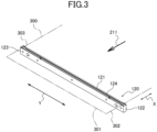
- FIG. 3 is a perspective view showing one example of the receiving member provided in the creasing device.
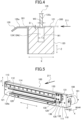
- FIG. 4 is a vertical cross-sectional view of a middle portion (position of line B-B in FIG. 10 ) of the receiving member of FIG. 3 .
- FIG. 5 is a front perspective view of the creasing device formed into a module.
- FIG. 6 is a rear perspective view of the creasing device of FIG. 5 .
- FIG. 1 is a schematic constitutional side view of a photo printer including a paper creasing device in the inside.
- FIG. 2 is a plan view of a sheet of paper with a width-directional crease formed by the creasing device.
- FIG. 3 is a perspective view showing one example of the receiving member provided in the crea
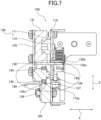
- FIG. 7 is a vertical cross-sectional view at a position of a rotary blade unit in the creasing device of FIG. 5 .
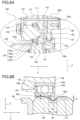
- FIG. 8A is a partial enlarged view of FIG. 7 .
- FIG. 8B is a partial enlarged view of FIG. 8A .
- FIG. 9 is a rear perspective view of the rotary blade unit.
- FIG. 10 is a plan view showing the groove formed on an upper surface of the receiving member of FIG. 3 .
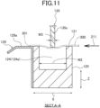
- FIG. 11 is a cross-sectional view showing a cross section taken along line A-A in FIG. 10 .
- FIG. 12 is a comparative perspective view of a creasing device of an embodiment and that of a comparative example, which are in alignment.
- FIG. 12 is a comparative perspective view of a creasing device of an embodiment and that of a comparative example, which are in alignment.
- FIG. 12 is a comparative perspective view of a creasing device of an embodiment and that of a comparative example, which
- FIG. 13 is a comparative back view showing a height comparison between the creasing device of the embodiment and that of the comparative example, which are in alignment.
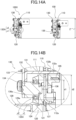
- FIG. 14A is a comparative vertical cross-sectional view showing a height comparison between the creasing device of the embodiment and that of the comparative example, which are in alignment.
- FIG. 14B is a partial enlarged view of the comparative example of FIG. 14A , which is similar to FIG. 8 .
- FIG. 15 is a comparative front view showing a width comparison between the creasing device of the embodiment and that of the comparative example, which are in alignment.
- FIG. 16 is a view showing one example of arrangement of the paper creasing device in a photo printer.
- a paper creasing device according to the present embodiment and an embodiment of a printer including the paper creasing device will be described as follows with reference to the drawings.
- FIGS. 1 to 16 are those for describing this embodiment.
- FIG. 1 is a configurative view of a printer 200, such as a photo printer.
- the printer 200 is of a so-called dye-sublimation thermal-transfer type.
- the printer 200 of a dye-sublimation thermal-transfer type prints by applying heat to an ink ribbon 231 under a condition that the ink ribbon 231 is pressed against a sheet of paper 300 to make a diffusion transfer of a sublimation dye, which has been applied to the ink ribbon, to the paper 300.
- the printer 200 includes in its inside a device 100 for creasing the paper 300.
- the paper 300 is, for example, one made by respectively attaching and applying multiple resin layers (receptive layers) to both of front and back surfaces of a core paper, and has a certain degree of rigidity.
- the paper 300 is, for example, 200 [ ⁇ m] thickness.
- the thickness of the paper 300 is not limited to 200 [ ⁇ m].
- the sublimation dye of the above-mentioned ink ribbon 231 is transferred by diffusion to the top surface resin layer of the paper 300.
- the printer 200 is a sheet-fed machine that prints on both sides of the paper 300, using sheet paper cut into rectangular sheets one by one as the paper 300.
- the printer 200 is an embodiment of the printer according to the present application.
- the printer 200 includes, inside an outer case 210, a paper storage section 220, a printing section 230 and a cutter 260 in sequence along a conveying path 211 of the paper 300.
- conveyors 240 are provided at various places of the conveying path 211.
- the creasing device 100 is a device for creasing the paper 300 and may be formed into a module to become an independent configuration.
- the creasing device 100 is attached to (built into) the printer 200, thereby providing the printer 200 with a creasing function.
- the creasing device 100 is installed between the printing section 230 and the cutter 260 inside the outer case 210.
- the installation position of the creasing device 100 is not limited to the above.
- the printer 200 includes a controller 250 inside the outer case 210.
- configuration of the printer is not limited to the above.
- the outer case 210 is formed into a generally rectangular shape in outline. It is preferable to make the outer case 210 as small as possible in terms of vertical, width and depth dimensions.
- the paper storage section 220 is a space or container (tray) that accommodates the paper 300 to be printed by the printer 200. The paper storage section 220 accommodates multiple sheets of the sheet paper 300 stacked in the thickness direction.
- the printing section 230 includes a thermal head 232 and a platen roller 233.
- the platen roller 233 and the thermal head 232 are positioned opposite each other so as to sandwich the ink ribbon 231 and the paper 300.
- the platen roller 233 works with the thermal head 232 to press the paper 300 against the ink ribbon 231.
- the thermal head 232 applies heat to the ink-applied ink ribbon 231 to make a diffusion transfer of a sublimation dye of the ink ribbon 231 to the resin layer of the paper 300 in contact with the ink ribbon 231, thereby making printing.
- a number of conveyors 240 are installed at various places along the conveying path 211 of the paper 300 in the outer case 210.
- the conveyor 240 is installed singly or in plurality between the paper storage section 220 and the printing section 230 to transport the paper 300 stored in the paper storage section 220 to the printing section 230.
- the conveyor 240 is installed singly or in plurality between the printing section 230 and the creasing device 100 to transport the paper 300, which has been printed at the printing section 230, to the creasing device 100 or the cutter 260.
- the conveyor 240 is installed inside the cutter 260 for the discharge to the outside of the printer 200, after a portion of the paper 300, which has been creased by the creasing device 100, is cut according to need by the cutter 260 to make a front edge 301 of the paper 300.
- the conveyor 240 includes transport rollers and a power transmission mechanism, a sensor, and a motor.
- the transport rollers and the power transmission mechanism move the paper 300 along the conveying path 211.
- the sensor is provided on the conveying path 211 to detect the paper 300.
- the sensor is an optical sensor, such as a photo reflector or photo interrupter, but may also be a mechanical sensor using a contact.
- the motor provides the conveyance force to the power transmission mechanism.
- the controller 250 controls each operation of the printing section 230, the conveyor 240, the cutter 260, and the creasing device 100.
- the controller 250 controls the operation of the motor to transport the paper 300, for example, based on the result of detection of the paper 300 by the sensor provided in the conveyor 240.
- the controller 250 controls the conveyor 240 and the printing section 230 to print on the paper 300 the content (a visible image such as landscape or snapshot photo) corresponding to the print data.
- the controller 250 controls the conveyor 240 and the creasing device 100 in accordance with preset operation commands, thereby forming a straight crease 310 on the printed paper 300 at a specified position such as near an edge portion or a center portion of the paper 300.
- FIG. 2 is a plan view of the paper 300 with the crease 310 in a width direction Y formed by the creasing device 100.
- the creasing device 100 forms, on the paper printed by the printing section 230, the straight crease 310, which extends in the width direction Y (direction perpendicular to a transport direction X), near the front edge 301 in the transport direction X by the conveyor 240.
- the crease 310 is not limited to near the front edge 301 in the transport direction X of the paper 300. For example, it may be formed on the center portion or near the rear edge in the transport direction X of the paper 300.
- This crease 310 is an indentation that induces a trace of folding along a fold of the paper 300.
- the crease 310 is formed in a condition that the paper 300 is placed on a receiving member 120 formed with a groove 124.
- a rotary blade 135 is brought into abutment at its blade portion (flange portion 135c) with a part of the groove 124 from above the paper 300 such that a part of the blade portion is inserted into the groove 124.
- the crease 310 is formed on the paper 300.
- FIGS. 5 to 7 are views showing the creasing device 100 of this embodiment.
- FIG. 5 is a front perspective view of the creasing device 100.
- FIG. 6 is a rear perspective view of the creasing device 100 shown in FIG. 5 .
- FIG. 7 is a vertical cross-sectional view of the creasing device 100 of FIG. 5 .
- FIG. 8A is a partial enlarged view of FIG. 7 .
- FIG. 8B is a partial enlarged view of FIG. 8A .
- the front of the creasing device 100 is described as the downstream side in the transport direction X of the paper 300 in the printer 200, and the rear of the creasing device 100 as the upstream side in the transport direction X.
- the creasing device 100 may be oriented in the opposite direction. That is, the front of the creasing device 100 may refer to the upstream side in the transport direction, and its rear side to the downstream side in the transport direction.
- the creasing device 100 includes the receiving member 120 ( FIG. 3 ) of the paper 300, a rotary blade unit 130 ( FIG. 9 ), and a moving mechanism 180, which are provided on a sheet metal frame 110 as a main body. These receiving member 120, rotary blade unit 130 and moving mechanism 180 are provided on the frame 110 and formed into a module. By incorporating such module into the printer 200, the printer 200 is provided with a creasing function.
- the frame 110 is a member extending in the width direction Y of the paper 300.
- the frame 110 includes a longitudinal plate 111 that is raised in an approximately vertical direction including the width direction Y of the paper 300.
- the longitudinal plate 111 is formed to have a relatively flat surface of a rectangular shape that is horizontally elongated in the width direction Y.
- This longitudinal plate 111 is formed at its lower part with an elongated hole 112 that passes therethrough and extends in the width direction Y.
- the elongated hole 112 serves as a passing slot of the paper 300 that allows the paper 300 in a flat state to pass therethrough along the transport direction X.
- the paper 300 is allowed to pass through the elongated hole 112 from the upstream side to the downstream side in the transport direction X.
- the creasing device 100 can also allow the paper 300 to pass through the elongated hole 112 from the downstream side to the upstream side in the transport direction X.
- the paper 300 is approximately horizontal in the width direction Y and the transport direction X, but it is not limited to this.
- the creasing device 100 is changed in its overall posture to match the orientation of the paper 300.
- the longitudinal plate 111 is formed, above the elongated hole 112, with a guide hole 113 that is parallel with the elongated hole 112, is spaced and passes therethrough.
- the guide hole 113 is formed to have a length that is longer than the elongated hole 112 in the width direction Y.
- the longitudinal plate 111 is provided, above the guide hole 113 on its front side, with a guide rail 114 along the guide hole 113.
- the frame 110, the elongated hole 112, the guide hole 113, and the guide rail 114 extend approximately in a horizontal direction.
- the front surface of the longitudinal plate 111 is a surface that faces the downstream side of the transport direction X.
- the guide rail 114 extends in parallel with the elongated hole 112 and the guide hole 113 and has a guiding function together with the guide hole 113.
- the receiving member 120 ( FIG. 3 ) of the paper 300 is integrally fixed, together with the after-mentioned paper guide member 129 ( FIG. 4 ), to the underside of the elongated hole 112 at the lower part on the front surface in the transport direction X of the longitudinal plate 111 of the frame 110.
- the receiving member 120 is formed into a square pillar shape extending long in the width direction Y of the paper 300.
- the receiving member 120 has a length in the longitudinal direction (width direction Y) that is slightly longer than the width of the paper 300.
- the receiving member 120 is fixed approximately flush to make its upper surface 121 along the lower edge of the elongated hole 112.
- the receiving member 120 is formed on its upper surface 121 with the groove 124 that extends straight along the longitudinal direction of the receiving member 120.
- the groove 124 is formed approximately at a center portion in the transport direction X on the upper surface 121 of the receiving member 120. Details of the groove 124 are described hereinafter.
- the paper guide member 129 is fixed to the front side surface in the transport direction X of the receiving member 120.
- the paper guide member 129 has the same length as that of the receiving member 120.
- the paper guide member 129 is formed, in a cross-section along a vertical plane including the transport direction X, into a generally L-shape that includes vertical and horizontal portions and is installed in an upside-down state.
- the paper guide member 129 is fixed, at its vertical plate corresponding to the vertical portion of the L-shape, to the front side surface of the receiving member 120.
- a horizontal plate corresponding to the horizontal portion of the L-shape is arranged to protrude forward in the transport direction X.
- An upper surface 129a of the horizontal plate of the paper guide member 129 is set, at least at its portion on the side of the receiving member 120, to approximately the same height as that of the upper surface 121 of the receiving member 120.
- the upper surface 129a of the horizontal portion of the paper guide member 129 may be monolithically formed, at its front portion in the transport direction X, with an inclined surface that slopes down toward the front.
- the paper 300 is fed, for example, through the elongated hole 112 formed in the frame, to the upper surface 121 of the receiving member 120 and the upper surface 129a of the paper guide member 129.
- the front edge 301 FIG.
- the paper 300 proceeds smoothly to the upper surface 129a without being caught by the longitudinal plate 111 of the paper guide member 129, thereby guiding a lower surface of the paper 300.
- the paper 300 may be allowed to pass through the elongated hole 112 via the receiving member 120 from the side of the paper guide member 129.
- FIG. 9 is a perspective view showing the rotary blade unit 130, which is a view seen from the side of the longitudinal plate 111.
- the rotary blade unit 130 is disposed on the front side in the transport direction X (same side as that of the receiving member 120) of the longitudinal plate 111 of the frame 110 ( FIGS. 5 and 7 ).
- the rotary blade unit 130 includes a guided member 131, a holding plate 133, and a support shaft 136.
- the support shaft 136 is a shaft for rotatably supporting the rotary blade 135.
- the support shaft 136 is attached to the holding plate 133, and the rotary blade 135 is attached to be rotatable around the support shaft 136.
- the rotary blade unit 130 includes an engaging plate 132.
- the rotary blade unit 130 integrally includes the guided member 131, the holding plate 133, the support shaft 136, the rotary blade 135, and the engaging plate 132.
- the guided member 131 is a movable body that is movable, without play, along the longitudinal direction (width direction Y) of the guide rail 114, and is slidably engaged with the guide rail 114.
- the guide rail 114 and the guided member 131 function as a linear guide (guide portion) that linearly guides the rotary blade unit 130 in its entirety at a constant height along the width direction Y.
- the guided member 131 is installed on a surface on the same side as that of the receiving member 120 of the longitudinal plate 111.
- the holding plate 133 is directly fixed to the front surface in the transport direction X of the guided member 131.
- the holding plate 133 is a member that attaches the rotary blade 135 and the engaging plate 132 to the guided member 131.
- the holding plate 133 is made to have a relatively flat surface and is disposed in parallel with the longitudinal plate 111.
- the holding plate 133 is formed to be vertically longer than the guided member 131.
- the holding plate 133 is installed to make a condition in which its upper portion is approximately aligned with an upper portion of the guided member 131 and to project its lower portion downwardly from a low portion of the guided member 131.
- a lower end portion of the holding plate 133 is installed at a position that is opposite the upper surface 129a of the paper guide member 129, not to reach the upper surface 129a of the paper guide member 129.
- An end portion of the support shaft 136 which extends rearward (side of the longitudinal plate 111) along the transport direction X, is press-fitted into a downwardly projecting portion of the holding plate 133, and is fixed by swaging so as to extend the press-fitted portion in a radial direction.
- the support shaft 136 is a stepped shaft member.
- a base portion which is closer to the holding plate 133, in a portion (projection portion) projecting rearward from the holding plate 133 is a position setting portion 134 that sets the position of the rotary blade 135 in the transport direction X.
- the position setting portion 134 is formed into a cylindrical shape with the largest diameter in the support shaft 136, and is installed on the holding plate 133 such that the lowest position in the height direction Z (or vertical direction) of the creasing device 100 becomes approximately the same position as that of the lower end portion of holding plate 133.
- the support shaft 136 is formed at its middle portion, which is ahead of the position setting portion 134, with a cylindrical middle-diameter portion, and at its tip with a cylindrical small-diameter portion.
- the position setting portion 134 is monolithically formed with the middle-diameter and small-diameter portions.
- the projection portion of the support shaft 136 is largely formed with almost three steps.
- the end portion of the support shaft 136, which is press-fitted into the holding plate 133, has approximately the same diameter as that of the small-diameter portion at the tip.
- the position setting portion 134 and the small-diameter portion are not limited to a cylindrical shape.
- the rotary blade 135 is fitted around the middle-diameter portion of the support shaft 136 to be rotatable around the support shaft 136.
- the middle-diameter portion is a shaft support portion with approximately the same diameter as an inner diameter of the rotary blade 135.
- the middle-diameter portion has a length that is approximately equivalent to the total thickness of the rotary blade 135.
- the rotary blade which is fitted around the middle-diameter portion, is positioned by the position setting portion 134 in the axial direction in a locked condition in the axial direction by bringing a side surface, which faces the side of the holding plate 133, into abutment with a stepped portion (locking surface) at a boundary between the position setting portion 134 of the support shaft 136 and the middle-diameter portion.
- the rotary blade 135 is fixed in a condition that a side surface facing the side of the frame 110 is locked in the axial direction by a retaining ring, such as E-ring 137, which is attached to a receiving groove 136a formed between the small-diameter portion and the middle-diameter portion.
- the flange portion 135c of an annular shape which projects externally in the radial direction of the radial bearing, is monolithically formed with the outer race 135b of the radial bearing. Originally, the flange portion 135c is formed on the outer race 135b to conduct at least one of locking and positioning in the axial direction relative to a component or member that fixes the outer race 135b of the radial bearing.
- the flange portion 135c is formed on an end portion of the outer race 135b, which is on the side of the longitudinal plate 111, and extends continuously with a constant projection in the radial direction. Therefore, a portion except the flange portion 135c on an outer circumferential surface of the outer race 135b is on the side of the holding plate 133 than the flange portion 135c and is positioned to be slightly upwardly away from the upper surface 121 of the receiving member 120. Lower end portions of the outer race 135b and the flange portion 135c become lower than a lower end portion of the position setting portion 134.
- the projection in the radial direction of the flange portion 135c is made to be around the thickness of the outer race 135b.
- An outer peripheral portion and its surrounding area of the flange portion 135c are used as a cutting portion (blade) of the rotary blade 135, instead of the original use for locking, positioning, etc.
- the outer peripheral portion of the flange portion 135c is used as a cutting edge portion to form the crease 310 on the paper 300 by a direct abutment with the paper 300.
- the flange portion 135c has a cylindrical surface with a constant thickness (blade thickness W3, FIG. 4 ) in the transport direction X.
- the cylindrical surface is a surface that is parallel with the axial direction and extends in the circumferential direction, thereby making a flat cutting edge.
- the blade thickness W3 of the flange portion 135c is roughly equivalent to the thickness of the outer race 135b.
- the outer peripheral portion of the flange portion 135c is chamfered at its corner portions. Therefore, the flange portion 135c is suitable for the use to form the crease 310 on the paper 300, without cutting the paper 300.
- the creasing device 100 can also be used as a device for cutting the paper 300.
- the lower end portion of the outer circumferential surface of the outer race 135b, except the flange portion 135c, is higher than the upper surface 121 of the receiving member 120 to form a gap S ( FIG. 8B ) between that and the upper surface 121.
- This gap S has a size that allows the paper 300 to pass therethrough and that suppresses rising of the paper 300 from the upper surface 121 of the receiving member 120 during the creasing. In other words, even if the paper 300 is tried to rise from the upper surface 121 by more than the gap S, the paper 300 is brought into abutment with the outer circumferential surface of the outer race 135b to prevent the paper 300 from rising.
- the outer circumferential surface of the outer race 135b acts as a rising prevention portion that prevents the paper 300 from rising.
- the gap S is 0.4 to 0.5 [mm] relative to the paper 300 having a thickness of 0.2 [mm].
- the elongated hole 112 may be formed, at its upper peripheral portion, with a rising prevention portion 112a ( FIG. 8A ) that prevents the paper 300 from rising during the creasing.
- This rising prevention portion 112a extends from the upper peripheral portion of the elongated hole 112 downward or diagonally downward toward the opposite side of the receiving member 120 to have about a length that does not reach the upper surface of the paper 300 which passes through the inside of the elongated hole 112.
- the rising prevention portion 112a which extends diagonally downward or the like, functions as a guiding taper for the paper 300.
- the rising prevention portion 112a may be formed, at its lower end portion, with a parallel portion that is parallel with the upper surface 121 of the receiving member 120.
- the rising prevention portion 112a is provided on a part of the upper peripheral portion of the elongated hole 112. As shown in FIG. 12 , the rising prevention portion 112a is provided at two positions except both end portions and a center portion of the elongated hole 112. For example, when the rising prevention portion 112a is formed by a cutting and bending process through pressing, a partial shallow cutout portion for securing a part that becomes the rising prevention portion 112a is formed at a position of a lower peripheral portion of the elongated hole 112, where the rising prevention portion 112a is provided. This shallow cutout portion is covered by a side surface of the receiving member 120. Therefore, there is no obstacle to make the paper 300 pass through the elongated hole 112.
- the rotary blade unit 130 becomes a movable part of the creasing device 100.
- the engaging plate 132 is fixed to a downwardly projecting portion of the holding plate 133 attached to the guided member 131.
- the engaging plate 132 is attached to a position that is higher than that of the rotary blade 135.
- the engaging plate 132 is formed into a generally L-shape including vertical and horizontal portions in a cross-section taken by a vertical plane including the transport direction X, and is installed in an upside-down state.
- a vertical plate corresponding to the vertical portion of the L-shape is fixed in a horizontal direction in an abutment condition with the holding plate 133, and a horizontal plate corresponding to the horizontal portion of the L-shape is engaged in abutment with a lower part of the guided member 131 from below.
- the vertical plate corresponding to the vertical portion of the L-shape is formed with an arcuate cutout for preventing interference with the position setting portion 134.
- the horizontal plate corresponding to the horizontal portion of the L-shape is formed with an engaging portion 132a that projects rearward in the transport direction X.
- the engaging portion 132a is formed at a center portion in the width of the horizontal plate.
- the engaging portion 132a passes through the guide hole 113 formed through the longitudinal plate 111 of the frame 110 and projects on the back side of the longitudinal plate 111. As shown in FIG. 6 , the engaging portion 132a is fixed to an endless timing belt 185 that is displaced along an outer circumference of the guide hole 113.
- the moving mechanism 180 includes a drive source that automatically moves the rotary blade 135 along the groove 124.
- the moving mechanism 180 is disposed on the back surface side of the longitudinal plate 111 of the frame 110.
- the moving mechanism 180 includes a DC motor 181 and a pinion gear 182 fixed to an output shaft of the DC motor 181.
- the moving mechanism 180 includes an intermediate gear 183 that meshes with the pinion gear 182, a drive pulley 184 that is coaxially provided with the intermediate gear 183, a driven pulley 186 that makes a pair with the drive pulley 184, and a timing belt 185.
- the timing belt 185 is formed, on its inner circumferential surface, with a linear tooth profile that meshes with the drive pulley 184 and the driven pulley 186, and is looped over the drive pulley 184 and the driven pulley 186.
- the drive and driven pulleys 184, 186 are installed at positions outside of both end portions of the guide hole 113 in a state that they are spaced away from each other.
- the DC motor 181, the pinion gear 182, and the intermediate gear 183 are installed at around an end portion of the guide hole 113, which is on the side of the drive pulley 184.
- the timing belt 185 is looped over the drive and driven pulleys 184, 186 which are installed outside the guide hole 113 with a space in the width direction Y, so as to be disposed in a horizontally extended manner to surround the outside of the contour of the guide hole 113.
- a fixing member 132b which mates with and holds the engaging portion 132a projecting rearward in the transport direction X through the guide hole 113, is fixed to the linear tooth profile.
- the fixing member 132b may be installed on either an upper line portion or a lower line portion of the timing belt 185.
- the upper and lower line portions are horizontally elongated portions along the guide hole 113, which are positioned on the upside and downside of the timing belt 185, and move in the opposite directions relative to each other. In the drawing, the fixing member 132b is fixed to the lower line portion of the timing belt 185.
- the timing belt 185 moves rotationally through the pinion gear 182, the intermediate gear 183, and drive pulley 184.
- the rotary blade unit 130 which is fixed to the timing belt 185, moves horizontally at a constant height in the width direction Y along the guide hole 113.
- the movement range of the rotary blade 135 by the moving mechanism 180 is set to a range from a position outside one end portion 122 in the width direction Y of the receiving member 120 to a position outside the other end portion 123.
- the moving mechanism 180 can switch the movement range of the rotary blade 135 to a range from the position outside the other end portion 123 in the width direction Y of the receiving member 120 to the position outside the one end portion 122.
- the moving mechanism 180 can reciprocatingly move the rotary blade 135 at a constant height along the width direction Y.
- the range, in which the rotary blade 135 is moved while maintaining a constant height is at least the range between the side edges 302, 303 of the paper 300 (range for creasing the paper 300). It is optional to change the height of the rotary blade 135 outside the side edge 302 (or side edge 303) of the paper 300 in the width direction Y.
- FIG. 10 is a plan view showing the groove 124 formed on the upper surface 121 of the receiving member 120.
- FIG. 11 is a sectional view showing a section taken by a plane along the line A-A (position of an outer range 124a) in FIG. 10 .
- FIG. 4 is a sectional view showing a section taken by a plane along the line B-B (position of an inner range 124b) in FIG. 10 .
- the groove 124 of the receiving member 120 may have a uniform width (groove width W1) over the whole length in the width direction Y.
- the groove is as follows.
- the paper 300 that has passed the elongated hole 112 is placed on the upper surface 121 of the receiving member 120, as shown by an imaginary line. Upon this, the paper 300 is positioned in the width direction Y such that its entire area in the width direction Y is placed on the upper surface 121.
- the one side edge 302 in the width direction Y of the paper 300 is disposed inside the one end portion 122 of the receiving member 120 in the width direction Y.
- the other side edge 303 (side edge 303 in the width direction Y) of the paper 300 is disposed inside the other end portion 123 of the receiving member 120 in the width direction Y.
- the groove 124 includes at least the outer range 124a and the inner range 124b in the width direction Y.
- the inner range 124b is a middle portion in the width direction Y that occupies most of the groove 124.
- the outer range 124a is a portion (around the edge) of a range with a predetermined length that is positioned outside the inner range 124b in the width direction Y.
- the outer range 124a is formed on at least one or both sides of the side edges 302, 303 of the paper 300.
- the outer range 124a of the groove 124 includes a starting point (starting point portion) where the rotary blade 135 begins to make a contact with the side edge 302, 303 of the paper disposed on the groove 124.
- the side edge 302, 303 of the paper 300 is the starting point portion.
- the inner range 124b has a constant groove width W1 ( FIG. 4 ).
- the constant groove width W1 is 1.2 to 1.4 [mm] as one example, it is not limited to 1.2 to 1.4 [mm] as its specifically applicable value.
- the outer range 124a has a constant groove width W2 (> groove width W1) that is wider than that of the inner range 124b ( FIG. 11 ).
- the constant groove width W2 is 4.0 [mm] as one example, it is not limited to 4.0 [mm] as its specifically applicable value.
- a connecting range 124c is formed between the outer range 124a and the inner range 124b of the groove 124.
- the connecting range 124c has an intermediate width between the groove width W2 of the outer range 124a and the groove width W1 of the inner range 124b.
- the connecting range 124c changes such that the width of the groove 124 narrows gradually from the outer range 124a toward the inner range 124b.
- the center of the connecting range 124c in the groove width direction (transport direction X) is aligned with the centers of the outer and inner ranges 124a, 124b in the groove width direction (transport direction X).
- the width of the groove 124 changes (decreases) proportionally to make a smooth connection from the outer range 124a of the wide groove width W2 to the inner range 124b of the narrow groove width W1.
- the portion of the connecting range 124c of the groove 124 has a contour with a tapered shape that is inclined straight to the width direction Y.
- the creasing device 100 having the above configuration makes a condition that the paper 300 is placed on the upper surface 121 of the receiving member 120. Under this condition, the rotary blade 135 moves in the width direction Y, for example, from the one end portion 122 of the receiving member 120 toward the other end portion 123 in the movable range by the moving mechanism 180. With this, the crease 310 is formed on the paper 300, as a trace of the movement of the flange portion 135c, at a portion sandwiched between the flange portion 135c of the radial bearing as the rotary blade 135 and the groove 124 on the upper surface 121 of the receiving member 120.
- the rotary blade 135 may form the crease 310 by moving in the width direction Y from the side of the other end portion 123 of the receiving member 120 toward the side of the one end portion 122.
- the rotary blade 135 is formed of the radial bearing that is a combination of the inner race 135a and the outer race 135b, and the blade portion of the rotary blade 135 is the flange portion 135c, which is monolithically formed with the outer race 135b, of the radial bearing.
- the creasing device 100 makes it possible to form the rotary blade 135 with the simplest configuration of only the radial bearing and to precisely move the rotary blade 135 along the groove 124.
- the rotary blade 135 begins to make a contact, at the flange portion 135c, with one of the side edges 302, 303 of the paper 300 in the outer range 124a of the groove 124, which is formed with the wide groove width W2 ( FIG. 11 ).
- the groove width W2 of the outer range 124a is greater than the groove width W1 ( FIG. 4 ) of the inner range 124b. Specifically, the groove width W2 is about three times the groove width W1.
- the shear force exerted on the paper 300 by being sandwiched between the flange portion 135c and the groove 124 is greater in the inner range 124b than in the outer range 124a.
- the crease in the width direction Y which is formed in a middle portion of the paper 300 in the inner range 124b, becomes dark with a clear linear outline.
- the shear force exerted on the paper 300 by being sandwiched between the flange portion 135c and the groove 124 becomes less in the outer range 124a than in the inner range 124b.
- the crease 310 which is formed around the side edges 302, 303 of the paper 300 in the outer range 124a, results in a paler or thinner outline, as compared with the crease 310, which is formed in the middle portion of the paper 300 in the inner range 124b.
- a strong shear force may be caused to the side edge 302, 303 to result in a rupture around the side edge 302, 303 of the paper 300.
- the groove width W2 of the outer range 124a which corresponds to the side edge 302, 303 of the paper 300, has been made wider than the groove width W1 of the inner range 124b. Therefore, when the flange portion 135c begins to make a contact with the side edge 302, 303 of the paper 300, the shear force exerted on the side edge 302, 303 is weakened. Thus, the outer range 124a makes it possible to prevent or suppress a rupture around the side edge 302, 303 of the paper 300.
- the creasing device 100 of the present embodiment is formed with the connecting range 124c, where the width of the groove narrows gradually, between the outer range 124a and the inner range 124b. Therefore, the shear force exerted on the paper 300 is gradually changed by the connecting range 124c, between the outer range 124a with the groove width W2 being wide and constant and the inner range 124b with the groove width W1 being narrow and constant. Therefore, for example, it is possible to prevent or suppress the stress on the paper 300, which is caused by an abrupt change of the shear force.
- the center in the groove width direction of the groove 124 in the outer range 124a is aligned with that in the inner range 124b.
- the center of the blade thickness W3 of the flange portion 135c of the rotary blade 135 does not deviate from the center in the groove width direction of the groove 124, between the outer range 124a and the inner range 124b, thereby forming the crease 310 in a straight line. Therefore, it is possible to equalize stresses acting on both edges in the width direction of the crease 310, thereby preventing or suppressing a rupture of the paper 300 that can be caused, for example, when the stress is biased on one edge. Similarly, it is possible to obtain the same advantageous effect as above even in the connecting range 124c by aligning the center in the groove width direction of the groove 124 in the connecting range 124c with those in the outer and inner ranges 124a, 124b.
- the moving mechanism 180 makes the flange portion 135c of the rotary blade unit 130 move in a rolling manner along the groove 124.
- the radial bearing is configured to be able to sandwich both surfaces of the paper 300 between the flange portion 135c and the groove 124. As long as this configuration is maintained, a separate member(s) may be attached to the radial bearing for some purpose(s).
- the flange portion 135c which is monolithically formed with the outer race 135b, serves as a blade portion of the rotary blade 135, and the blade portion (flange portion 135c) is moved by the moving mechanism 180. With this, the flange portion 135c enters the groove 124 to form the crease 310 in the width direction Y on the paper 300 sandwiched between the flange portion 135c and the groove 124.
- the radial bearing and the receiving member 120 are arranged in such a positional relationship that the flange portion 135c of the outer race 135b is used as it is as a blade portion, and the flange portion 135c of the radial bearing is used differently from its original use. In this way, the improvement on the use of the radial bearing can make the radial bearing itself act as the rotary blade 135 to directly form the crease 310 on the paper 300.
- the flange portion 135c of the radial bearing is provided for the purpose of fixing or positioning the radial bearing to some member.
- the outer circumferential surface of the flange portion 135c is not sharply formed like a cutting blade. Therefore, the flange portion 135c of the radial bearing is suitable for the use to directly form the crease 310 without cutting the paper 300.
- FIGS. 12 to 15 are views showing a side-by-side size comparison between the creasing device 100 of this embodiment and a creasing device 100X of a comparative example.
- the comparative example has a hypothetical configuration, which is created based on the present embodiment, and does not actually exist.
- FIGS. 12 to 15 include only minimal signs.
- the creasing device 100X of the comparative example is one in which a rotary blade 135X is configured by attaching a separate component x1 (ring blade) as a blade portion to an outer circumference of a radial bearing x2.
- the radial bearing x2 of the comparative example has a cylindrical outer race with no flange portion.
- the separate component x1 as the ring blade is formed, at its outer circumferential surface, with a conical surface and, at its largest diameter portion, with a flange portion.
- the remaining configuration is the same as that of the present embodiment.
- the radial bearing x2 is used only as a component to reduce the frictional force against rotation.
- the creasing device 100X of the comparative example uses the separate component x1 and the radial bearing x2 for the rotary blade 135X. This increases the number of components to be used, and requires the assembly of the separate component x1 and the radial bearing x2 to increase the cost. Thus, the rotary blade 135X and the creasing device 100X of the comparative example become complicated in configuration.
- the separate component x1 as a blade portion is not used, and the radial bearing itself acts as the rotary blade 135. Therefore, it becomes possible to decrease the number of components and eliminate the attachment work of the separate component x1 as a blade portion to the radial bearing, thereby reducing the cost.
- the rotary blade 135 and the creasing device 100 are simplified in configuration.
- the rotary blade 135X is a combined component prepared by covering the outer circumferential side of the radial bearing x2 with the separate component x1 as a blade portion.
- the rotary blade 135 of the creasing device 100 of this embodiment is configured by only the radial bearing as a single component. Therefore, the diameter of the flange portion 135c of the radial bearing itself becomes the diameter of the rotary blade 135.
- the flange portion 135c is a site that is small in projection in the radial direction. Therefore, the total diameter of the rotary blade 135 becomes approximately the same diameter as that of the outer race 135b of the radial bearing (that is, a diameter made by increasing a diameter d1 of the radial bearing x2 of FIG. 14B by the part of the flange portion 135c), thereby being minimized.
- the creasing device 100 of this embodiment is made small, due to that the diameter of the rotary blade 135 has become smaller as compared with a diameter d2 of the rotary blade 135 of the creasing device 100X of the comparative example.
- the creasing device 100 of this embodiment can be made smaller by at least one size in the height direction Z ( FIGS. 13 and 14A ) and the width direction Y ( FIG. 15 ) than the creasing device 100X of the comparative example.
- the rotary blade 135 is composed of only the radial bearing by eliminating the separate component x1 as a blade portion like that of the creasing device 100X of the comparative example. Therefore, in the rotary blade 135, the precision of the radial bearing itself as a single body becomes the precision of the rotary blade 135 as a whole. Thus, the rotary blade 135 can improve the precision of processing the crease 310 on the paper 300. In addition, due to no accumulation of errors and plays by multiple components, the rotary blade 135 becomes less in error and play.
- a support shaft 136 for supporting the rotary blade 135 may include a position setting portion 134 that positions a side surface of the inner race 135a of the rotary blade 135 in an axial direction such that the flange portion 135c matches with a position of the groove 124.
- the position setting portion 134 holds the rotary blade 135 in the axial direction in a condition that the side surface of the inner race 135a of the rotary blade 135 is locked in the axial direction.
- the position setting portion 134 can precisely position the flange portion 135c relative to the groove 124 by its thickness in the axial direction.
- the flange portion 135c of the rotary blade 135 is positioned by the setting of the thickness in the axial direction of the position setting portion 134 such that the center of the blade thickness W3 aligns with the center in the groove width direction of the groove 124.
- the position setting portion 134 can precisely position the flange portion 135c relative to the groove 124, thereby obtaining the creasing device 100, which is free from the variation in production and which can form the clear and optimal crease 310 on the paper 300.
- the flange portion 135c becomes close to the groove 124 by the variation in production, it tends to shear the paper 300.
- the flange portion 135c becomes far from the groove 124, the shear force becomes weak to result in a weak creasing.
- the creasing device 100 of this embodiment can prevent such problems.
- the outer race 135b of the radial bearing may be spaced away from an upper surface 121 of the receiving member 120 to have a gap S of a dimension that is greater than a thickness of the paper 300.
- the outer race 135b of the radial bearing may be disposed at a position where the paper 300, which has been raised from the upper surface 121 of the receiving member 120, is brought into abutment therewith.
- the outer race 135b of the radical bearing which has been spaced away to have the gap S, suppresses raising of the paper 300 during the creasing.
- the receiving member 120 may be attached to a longitudinal plate 111 having an elongated hole 112 that allows the paper 300 to pass therethrough.
- the rotary blade 135 may be attached to a surface of the longitudinal plate 111 that is on the same side thereof as the receiving member is.
- the rotary blade 135 may be attached via a guide portion (linear guide formed of a guide rail 114 and a guided member 131) that guides the rotary blade 135 to move along the groove 124.
- the rotary blade 135 may be attached via the guide portion by using the support shaft 136 to a holding plate 133 that is installed to be parallel with the longitudinal plate.
- the linear guide and the radial bearing, which becomes the rotary blade 135, are commercially available products with guaranteed precision. Since the longitudinal plate 111 and the holding plate 133 are almost flat plates, it is easy to achieve the machining precision, and since they are directly attached to each other via the linear guide, it is easy to achieve the attachment precision. Therefore, it is possible to make the creasing device 100 into a device with a simple structure and a high precision in the height direction Z and the transport direction X.
- the support shaft 136 makes it possible to easily position the rotary blade 135 in the height direction Z and the transport direction X.
- the position setting portion 134 positions the rotary blade 135 in the height direction Z and the transport direction X by providing the support shaft 136 with the position setting portion 134.
- a printer 200 including the above creasing device 100 can obtain advantageous effects similar to those of the creasing device 100.
- FIG. 16 is a vertical cross-sectional view showing another photo printer 200' (hereinafter referred to as printer 200') including the creasing device 100, showing a disposition example of the creasing device 100 in the printer.
- printer 200' is another embodiment of the printer according to the present application.
- the printer 200 shown in FIG. 1 includes the creasing device 100, which is disposed at a position close to the cutter 260 provided in the vicinity of an outlet of the paper 300 in the printer 200, that is, at an upper front side of the printer 200.
- the printer 200' shown in FIG. 16 includes the creasing device 100 to be disposed below around a center portion in the front-rear directions (see the transport direction X in the drawing) of the printer 200'.
- the center portion is at a position at the center in the front-rear directions of the printer 200', and around the center portion refers to the center portion and its surrounding.
- the creasing device 100 is disposed at a position that is displaced slightly rearward from the center portion.
- the printer 200' is also a printer of a dye-sublimation thermal-transfer type, similar to the printer 200.
- the printer 200' can select either sheet paper 306, which is cut paper, or roll paper 307, which is formed into a roll by rolling a long strip of paper.
- the printer 200' includes an outer case 210, a sheet paper storage section 221, a roll paper storage section 222, a printing section 230, a cutter 260, the creasing device 100, a conveying portion 241 and conveying paths 242 for composing conveyors 240, and a controller 250.
- the printing section 230, the cutter 260, and the controller 250 in the printer 200' are disposed at positions similar to those of the printing section 230, the cutter 260, and the controller 250 in the printer 200, respectively.
- the sheet paper storage section 221 is a paper storage section that stores many sheets of the sheet paper 306 by stacking them in the thickness direction, and is disposed at a lower end portion of the printer 200', similar to the paper storage section 220 in the printer 200 shown in FIG. 1 .
- the roll paper storage section 222 is a paper storage section (space) that stores the roll paper 307, and is disposed at a position that is in front of the printing section 230 in the printer 200' and that is above the sheet paper storage section 221.
- the printer 200' includes a front outlet 242a for discharging the sheet paper 306 or roll paper 307 after printing in the printing section 230, to the outside toward the front, and an upper outlet 242b for discharging that to a discharge tray toward the back.
- the front outlet 242a is provided at an upper part on a front side surface of the printer 200', and the upper outlet 242b is provided to be open rearward at an upper part or upper surface of the printer 200'.
- the discharge tray is provided at an upper part or upper surface of the printer 200'.
- the printer 200' discharges the sheet paper 306 or roll paper 307 to the outside of the front of the printer 200' or to the discharge tray of an upper part thereof by the controller 250 selectively switching between the front outlet 242a and the upper outlet 242b.
- the creasing device 100 is disposed, rearward in the front-rear directions than the roll paper storage section 222, at around a center portion in the front-rear directions (transport direction X) of the printer 200'.
- the creasing device 100 is disposed at a position that is above the sheet paper storage section 221 provided at a lower end portion of the printer 200' and that is below the printing section 230 provided with the ink ribbon 231 and the thermal head 232.
- the position, where the creasing device 100 has been disposed, is a region that tends to become a hard-to-use space in the printer 200'. Therefore, it is possible to put the creasing device 100 into the above region without enlarging the printer 200' in the front-rear directions, thereby effectively using space in the printer 200'.
- the creasing device 100 is disposed at around the center portion in the front-rear directions of the printer 200'.
- the creasing device 100 may be disposed, in the middle of a creasing path 243 extending to the rear along the front-rear direction, below the roll paper storage section 222, of the conveying path 242. With this, the printer 200' can form the crease 310 at around either end in the transport direction X of the sheet paper 306, which passes through the creasing path 243, by the creasing device 100 disposed at around the center portion in the front-rear direction.
- the printer 200' can form the crease 310 at the center portion, too, in the transport direction X of the sheet paper 306, which passes through the creasing path 243, by the creasing device 100 disposed at around the center portion in the front-back direction.
- each sheet paper 306 it is possible to improve openability of each sheet paper 306, for example, when a photo book has been made by binding multiple sheets of the printed sheet paper 306, by the creasing device 100 forming the crease 310 at around an end portion in the transport direction X of the sheet paper 306. Furthermore, for example, it is possible to form a fold at the center of a greeting card made by a single sheet of the sheet paper 306 by the creasing device 100 forming the crease 310 at around the center portion in the transport direction X of the sheet paper 306.
- the creasing device 100 is incorporated as a module into the printer 200, and the moving mechanism 180 operates by the control of the controller 250 of the printer 200.
- the creasing device 100 may be configured as a single device that is independent from the printer 200, by including an outer case, which covers the entirety of the creasing device 100, and a control part, which relates to the operation of the moving mechanism 180, of the controller 250.
Landscapes
- Engineering & Computer Science (AREA)
- Mechanical Engineering (AREA)
- Life Sciences & Earth Sciences (AREA)
- Forests & Forestry (AREA)
- Folding Of Thin Sheet-Like Materials, Special Discharging Devices, And Others (AREA)
Abstract
To provide a creasing device that can be made more compact by an improvement on a rotary blade. A device 100 for creasing a paper 300 includes a receiving member 12 provided with a groove 124 that extends in a fixed direction; a rotary blade 135 that is configured to be movable along the groove 124; and a moving mechanism 180 for moving the rotary blade 135 along the groove 124. The rotary blade 135 includes a radial bearing that is formed of a combination of an inner race 135a and an outer race 135b, the radial bearing including a flange portion 135c that is monolithically formed with the outer race 135b. The radial bearing is configured to move by the moving mechanism 180, while the radial bearing sandwiches the paper 300 between the flange portion 135c and the groove 124 and keeps a condition in which the flange portion 135c is inserted in the groove 124.
Description
- The present application relates to a paper creasing device and a printer.
- As a post- or pre-processing device for printing, creasers are known to crease paper. A creaser is a device that forms a crease(s) on relatively thick paper or paper with high rigidity and stiffness. For example, when multiple sheets of the above-mentioned stiff paper are bound together, even if one tries to open each page by turning over the paper, it is not possible to fully open the same, due to stiffness of the paper, resulting in poor openability.
- For example, it is optional to make a photo book by printing a photograph(s), etc. on each resin layer of a printing paper prepared by respectively forming dye-receptive layers (receptive layers) on both of the front and back surfaces of a core paper and then bundling multiple sheets of the printing paper. Even in such photo book, similar to the above-mentioned paper, the poor openability condition could happen.
- Thus, if a crease is formed in advance by a creasing device in the vicinity of a bound part of the photo book, when the pages are opened, it becomes possible to fully open the pages by the crease as a fold, thereby improving openability.
- There are also cards, such as greeting cards, which are made of thick paper folded in the center. Greeting cards are finished by inwardly folding the side with the printed message. When the recipient opens the greeting card, the message appears from the inside. In such a case, when the center of the paper is creased to make a fold, it is possible to obtain a well-finished card by preventing a problem in which, when the paper is folded, the fold deviates, bends or spreads from the center, due to stiffness of the paper.
- A creasing device forms a crease on paper by sandwiching both sides of the paper between a groove extending in a predetermined direction and a blade that is fitted into the groove. Here, there is a rotary creasing device that uses a rotating blade (rotary blade) rotating along the groove (see, for example, Patent Document 1).
- The rotary creasing device places paper on a receiving member formed with a groove, presses a rotary blade against a part of the paper, which corresponds to the groove, from above the paper, and moves the rotary blade along the groove with its rotation, thereby forming a crease along the groove on the paper.
- Patent Literature 1:
JP 2009-286124A - In the rotary creasing device, the rotary blade has been made to rotate by using a bearing. The rotary blade is formed by covering an outer circumference of the bearing with a component that serves as a blade. Therefore, the rotary blade has a double structure of the bearing and the component that serves as a blade, thereby causing the rotary blade as a whole to have a larger diameter. This has been causing the rotary creasing device to have a larger size.
- The present application was made in view of the above situation, and its object is to provide a paper creasing device and a printer, in which the device can be made more compact by an improvement on the rotary blade.
- According to a first aspect of the present application, there is provided a paper creasing device, including a receiving member provided with a groove that extends in a fixed direction; a rotary blade that is configured to be movable along the groove; and a moving mechanism for moving the rotary blade along the groove, wherein the rotary blade includes a radial bearing that is formed of a combination of an inner race and an outer race, the radial bearing including a flange portion that is monolithically formed with the outer race, wherein the radial bearing is configured to move by the moving mechanism, while the radial bearing sandwiches a paper between the flange portion and the groove and keeps a condition in which the flange portion is inserted in the groove.
- According to a second aspect of the present application, there is provided a printer including the paper creasing device according to the first aspect of the present application.
- In a paper creasing device and a printer according to the present application, the device can be made more compact by an improvement on the rotary blade as in the above configuration.
-
FIG. 1 is a schematic constitutional side view of a photo printer including a paper creasing device in the inside.FIG. 2 is a plan view of a sheet of paper with a width-directional crease formed by the creasing device.FIG. 3 is a perspective view showing one example of the receiving member provided in the creasing device.FIG. 4 is a vertical cross-sectional view of a middle portion (position of line B-B inFIG. 10 ) of the receiving member ofFIG. 3 .FIG. 5 is a front perspective view of the creasing device formed into a module.FIG. 6 is a rear perspective view of the creasing device ofFIG. 5 .FIG. 7 is a vertical cross-sectional view at a position of a rotary blade unit in the creasing device ofFIG. 5 .FIG. 8A is a partial enlarged view ofFIG. 7 .FIG. 8B is a partial enlarged view ofFIG. 8A .FIG. 9 is a rear perspective view of the rotary blade unit.FIG. 10 is a plan view showing the groove formed on an upper surface of the receiving member ofFIG. 3 .FIG. 11 is a cross-sectional view showing a cross section taken along line A-A inFIG. 10 .FIG. 12 is a comparative perspective view of a creasing device of an embodiment and that of a comparative example, which are in alignment.FIG. 13 is a comparative back view showing a height comparison between the creasing device of the embodiment and that of the comparative example, which are in alignment.FIG. 14A is a comparative vertical cross-sectional view showing a height comparison between the creasing device of the embodiment and that of the comparative example, which are in alignment.FIG. 14B is a partial enlarged view of the comparative example ofFIG. 14A , which is similar toFIG. 8 .FIG. 15 is a comparative front view showing a width comparison between the creasing device of the embodiment and that of the comparative example, which are in alignment.FIG. 16 is a view showing one example of arrangement of the paper creasing device in a photo printer. - A paper creasing device according to the present embodiment and an embodiment of a printer including the paper creasing device will be described as follows with reference to the drawings.
-
FIGS. 1 to 16 are those for describing this embodiment. - Configuration of this embodiment is described in the following.
-
FIG. 1 is a configurative view of aprinter 200, such as a photo printer. Theprinter 200 is of a so-called dye-sublimation thermal-transfer type. Theprinter 200 of a dye-sublimation thermal-transfer type prints by applying heat to anink ribbon 231 under a condition that theink ribbon 231 is pressed against a sheet ofpaper 300 to make a diffusion transfer of a sublimation dye, which has been applied to the ink ribbon, to thepaper 300. Theprinter 200 includes in its inside adevice 100 for creasing thepaper 300. - The
paper 300 is, for example, one made by respectively attaching and applying multiple resin layers (receptive layers) to both of front and back surfaces of a core paper, and has a certain degree of rigidity. Thepaper 300 is, for example, 200 [µm] thickness. The thickness of thepaper 300 is not limited to 200 [µm]. - The sublimation dye of the above-mentioned
ink ribbon 231 is transferred by diffusion to the top surface resin layer of thepaper 300. Theprinter 200 is a sheet-fed machine that prints on both sides of thepaper 300, using sheet paper cut into rectangular sheets one by one as thepaper 300. - The
printer 200 is an embodiment of the printer according to the present application. Theprinter 200 includes, inside anouter case 210, apaper storage section 220, aprinting section 230 and acutter 260 in sequence along a conveyingpath 211 of thepaper 300. At various places of the conveyingpath 211,conveyors 240 are provided. - The
creasing device 100 is a device for creasing thepaper 300 and may be formed into a module to become an independent configuration. Thecreasing device 100 is attached to (built into) theprinter 200, thereby providing theprinter 200 with a creasing function. In the drawing, thecreasing device 100 is installed between theprinting section 230 and thecutter 260 inside theouter case 210. However, the installation position of thecreasing device 100 is not limited to the above. - The
printer 200 includes acontroller 250 inside theouter case 210. However, configuration of the printer is not limited to the above. - Here, the
outer case 210 is formed into a generally rectangular shape in outline. It is preferable to make theouter case 210 as small as possible in terms of vertical, width and depth dimensions. Thepaper storage section 220 is a space or container (tray) that accommodates thepaper 300 to be printed by theprinter 200. Thepaper storage section 220 accommodates multiple sheets of thesheet paper 300 stacked in the thickness direction. - The
printing section 230 includes athermal head 232 and aplaten roller 233. Theplaten roller 233 and thethermal head 232 are positioned opposite each other so as to sandwich theink ribbon 231 and thepaper 300. Theplaten roller 233 works with thethermal head 232 to press thepaper 300 against theink ribbon 231. Thethermal head 232 applies heat to the ink-appliedink ribbon 231 to make a diffusion transfer of a sublimation dye of theink ribbon 231 to the resin layer of thepaper 300 in contact with theink ribbon 231, thereby making printing. - A number of
conveyors 240 are installed at various places along the conveyingpath 211 of thepaper 300 in theouter case 210. For example, theconveyor 240 is installed singly or in plurality between thepaper storage section 220 and theprinting section 230 to transport thepaper 300 stored in thepaper storage section 220 to theprinting section 230. Theconveyor 240 is installed singly or in plurality between theprinting section 230 and thecreasing device 100 to transport thepaper 300, which has been printed at theprinting section 230, to thecreasing device 100 or thecutter 260. Theconveyor 240 is installed inside thecutter 260 for the discharge to the outside of theprinter 200, after a portion of thepaper 300, which has been creased by thecreasing device 100, is cut according to need by thecutter 260 to make afront edge 301 of thepaper 300. - The
conveyor 240 includes transport rollers and a power transmission mechanism, a sensor, and a motor. The transport rollers and the power transmission mechanism move thepaper 300 along the conveyingpath 211. The sensor is provided on the conveyingpath 211 to detect thepaper 300. The sensor is an optical sensor, such as a photo reflector or photo interrupter, but may also be a mechanical sensor using a contact. The motor provides the conveyance force to the power transmission mechanism. - The
controller 250 controls each operation of theprinting section 230, theconveyor 240, thecutter 260, and thecreasing device 100. Thecontroller 250 controls the operation of the motor to transport thepaper 300, for example, based on the result of detection of thepaper 300 by the sensor provided in theconveyor 240. - Based on the print data input and stored prior to printing, the
controller 250 controls theconveyor 240 and theprinting section 230 to print on thepaper 300 the content (a visible image such as landscape or snapshot photo) corresponding to the print data. - The
controller 250 controls theconveyor 240 and thecreasing device 100 in accordance with preset operation commands, thereby forming astraight crease 310 on the printedpaper 300 at a specified position such as near an edge portion or a center portion of thepaper 300. -
FIG. 2 is a plan view of thepaper 300 with thecrease 310 in a width direction Y formed by thecreasing device 100. For example, thecreasing device 100 forms, on the paper printed by theprinting section 230, thestraight crease 310, which extends in the width direction Y (direction perpendicular to a transport direction X), near thefront edge 301 in the transport direction X by theconveyor 240. Thecrease 310 is not limited to near thefront edge 301 in the transport direction X of thepaper 300. For example, it may be formed on the center portion or near the rear edge in the transport direction X of thepaper 300. - This
crease 310 is an indentation that induces a trace of folding along a fold of thepaper 300. As shown in the perspective view ofFIG. 3 , thecrease 310 is formed in a condition that thepaper 300 is placed on a receivingmember 120 formed with agroove 124. Under this condition, as shown in the vertical cross-sectional view ofFIG. 4 , arotary blade 135 is brought into abutment at its blade portion (flange portion 135c) with a part of thegroove 124 from above thepaper 300 such that a part of the blade portion is inserted into thegroove 124. With this, thecrease 310 is formed on thepaper 300. -
FIGS. 5 to 7 are views showing thecreasing device 100 of this embodiment. -
FIG. 5 is a front perspective view of thecreasing device 100.FIG. 6 is a rear perspective view of thecreasing device 100 shown inFIG. 5 .FIG. 7 is a vertical cross-sectional view of thecreasing device 100 ofFIG. 5 .FIG. 8A is a partial enlarged view ofFIG. 7 .FIG. 8B is a partial enlarged view ofFIG. 8A . - In the following, for clarity in relation to
FIG. 1 , the front of thecreasing device 100 is described as the downstream side in the transport direction X of thepaper 300 in theprinter 200, and the rear of thecreasing device 100 as the upstream side in the transport direction X. However, thecreasing device 100 may be oriented in the opposite direction. That is, the front of thecreasing device 100 may refer to the upstream side in the transport direction, and its rear side to the downstream side in the transport direction. - As mainly shown in
FIG. 5 , thecreasing device 100 includes the receiving member 120 (FIG. 3 ) of thepaper 300, a rotary blade unit 130 (FIG. 9 ), and a movingmechanism 180, which are provided on asheet metal frame 110 as a main body. These receivingmember 120,rotary blade unit 130 and movingmechanism 180 are provided on theframe 110 and formed into a module. By incorporating such module into theprinter 200, theprinter 200 is provided with a creasing function. - The
frame 110 is a member extending in the width direction Y of thepaper 300. Theframe 110 includes alongitudinal plate 111 that is raised in an approximately vertical direction including the width direction Y of thepaper 300. Thelongitudinal plate 111 is formed to have a relatively flat surface of a rectangular shape that is horizontally elongated in the width direction Y. Thislongitudinal plate 111 is formed at its lower part with anelongated hole 112 that passes therethrough and extends in the width direction Y. Theelongated hole 112 serves as a passing slot of thepaper 300 that allows thepaper 300 in a flat state to pass therethrough along the transport direction X. Thepaper 300 is allowed to pass through theelongated hole 112 from the upstream side to the downstream side in the transport direction X. However, thecreasing device 100 can also allow thepaper 300 to pass through theelongated hole 112 from the downstream side to the upstream side in the transport direction X. In the drawing, thepaper 300 is approximately horizontal in the width direction Y and the transport direction X, but it is not limited to this. When thepaper 300 is allowed to pass through theelongated hole 112 in an orientation other than horizontal, thecreasing device 100 is changed in its overall posture to match the orientation of thepaper 300. - The
longitudinal plate 111 is formed, above theelongated hole 112, with aguide hole 113 that is parallel with theelongated hole 112, is spaced and passes therethrough. Theguide hole 113 is formed to have a length that is longer than theelongated hole 112 in the width direction Y. Thelongitudinal plate 111 is provided, above theguide hole 113 on its front side, with aguide rail 114 along theguide hole 113. In the drawing, theframe 110, theelongated hole 112, theguide hole 113, and theguide rail 114 extend approximately in a horizontal direction. The front surface of thelongitudinal plate 111 is a surface that faces the downstream side of the transport direction X. Theguide rail 114 extends in parallel with theelongated hole 112 and theguide hole 113 and has a guiding function together with theguide hole 113. - The receiving member 120 (
FIG. 3 ) of thepaper 300 is integrally fixed, together with the after-mentioned paper guide member 129 (FIG. 4 ), to the underside of theelongated hole 112 at the lower part on the front surface in the transport direction X of thelongitudinal plate 111 of theframe 110. The receivingmember 120 is formed into a square pillar shape extending long in the width direction Y of thepaper 300. The receivingmember 120 has a length in the longitudinal direction (width direction Y) that is slightly longer than the width of thepaper 300. The receivingmember 120 is fixed approximately flush to make itsupper surface 121 along the lower edge of theelongated hole 112. - On the
upper surface 121 as one side of the square pillar of the receivingmember 120, thepaper 300 is placed. The receivingmember 120 is formed on itsupper surface 121 with thegroove 124 that extends straight along the longitudinal direction of the receivingmember 120. Thegroove 124 is formed approximately at a center portion in the transport direction X on theupper surface 121 of the receivingmember 120. Details of thegroove 124 are described hereinafter. - The
paper guide member 129 is fixed to the front side surface in the transport direction X of the receivingmember 120. Thepaper guide member 129 has the same length as that of the receivingmember 120. Thepaper guide member 129 is formed, in a cross-section along a vertical plane including the transport direction X, into a generally L-shape that includes vertical and horizontal portions and is installed in an upside-down state. Thepaper guide member 129 is fixed, at its vertical plate corresponding to the vertical portion of the L-shape, to the front side surface of the receivingmember 120. In thepaper guide member 129, a horizontal plate corresponding to the horizontal portion of the L-shape is arranged to protrude forward in the transport direction X. - An
upper surface 129a of the horizontal plate of thepaper guide member 129 is set, at least at its portion on the side of the receivingmember 120, to approximately the same height as that of theupper surface 121 of the receivingmember 120. Theupper surface 129a of the horizontal portion of thepaper guide member 129 may be monolithically formed, at its front portion in the transport direction X, with an inclined surface that slopes down toward the front. Thepaper 300 is fed, for example, through theelongated hole 112 formed in the frame, to theupper surface 121 of the receivingmember 120 and theupper surface 129a of thepaper guide member 129. When thepaper 300 proceeds from theupper surface 121 of the receivingmember 120 to theupper surface 129a of thepaper guide member 129, the front edge 301 (FIG. 2 ) of thepaper 300 proceeds smoothly to theupper surface 129a without being caught by thelongitudinal plate 111 of thepaper guide member 129, thereby guiding a lower surface of thepaper 300. Contrary to the above, thepaper 300 may be allowed to pass through theelongated hole 112 via the receivingmember 120 from the side of thepaper guide member 129. -
FIG. 9 is a perspective view showing therotary blade unit 130, which is a view seen from the side of thelongitudinal plate 111. Therotary blade unit 130 is disposed on the front side in the transport direction X (same side as that of the receiving member 120) of thelongitudinal plate 111 of the frame 110 (FIGS. 5 and7 ). - The
rotary blade unit 130 includes a guidedmember 131, a holdingplate 133, and asupport shaft 136. Thesupport shaft 136 is a shaft for rotatably supporting therotary blade 135. Thesupport shaft 136 is attached to the holdingplate 133, and therotary blade 135 is attached to be rotatable around thesupport shaft 136. Therotary blade unit 130 includes anengaging plate 132. Therotary blade unit 130 integrally includes the guidedmember 131, the holdingplate 133, thesupport shaft 136, therotary blade 135, and theengaging plate 132. - The guided
member 131 is a movable body that is movable, without play, along the longitudinal direction (width direction Y) of theguide rail 114, and is slidably engaged with theguide rail 114. Theguide rail 114 and the guidedmember 131 function as a linear guide (guide portion) that linearly guides therotary blade unit 130 in its entirety at a constant height along the width direction Y. The guidedmember 131 is installed on a surface on the same side as that of the receivingmember 120 of thelongitudinal plate 111. - The holding
plate 133 is directly fixed to the front surface in the transport direction X of the guidedmember 131. The holdingplate 133 is a member that attaches therotary blade 135 and theengaging plate 132 to the guidedmember 131. The holdingplate 133 is made to have a relatively flat surface and is disposed in parallel with thelongitudinal plate 111. The holdingplate 133 is formed to be vertically longer than the guidedmember 131. - The holding
plate 133 is installed to make a condition in which its upper portion is approximately aligned with an upper portion of the guidedmember 131 and to project its lower portion downwardly from a low portion of the guidedmember 131. A lower end portion of the holdingplate 133 is installed at a position that is opposite theupper surface 129a of thepaper guide member 129, not to reach theupper surface 129a of thepaper guide member 129. An end portion of thesupport shaft 136, which extends rearward (side of the longitudinal plate 111) along the transport direction X, is press-fitted into a downwardly projecting portion of the holdingplate 133, and is fixed by swaging so as to extend the press-fitted portion in a radial direction. - As shown in the partial enlarged cross-sectional views of
FIGS. 8A and 8B , thesupport shaft 136 is a stepped shaft member. In thesupport shaft 136, a base portion, which is closer to the holdingplate 133, in a portion (projection portion) projecting rearward from the holdingplate 133 is aposition setting portion 134 that sets the position of therotary blade 135 in the transport direction X. Theposition setting portion 134 is formed into a cylindrical shape with the largest diameter in thesupport shaft 136, and is installed on the holdingplate 133 such that the lowest position in the height direction Z (or vertical direction) of thecreasing device 100 becomes approximately the same position as that of the lower end portion of holdingplate 133. - The
support shaft 136 is formed at its middle portion, which is ahead of theposition setting portion 134, with a cylindrical middle-diameter portion, and at its tip with a cylindrical small-diameter portion. Theposition setting portion 134 is monolithically formed with the middle-diameter and small-diameter portions. The projection portion of thesupport shaft 136 is largely formed with almost three steps. The end portion of thesupport shaft 136, which is press-fitted into the holdingplate 133, has approximately the same diameter as that of the small-diameter portion at the tip. Theposition setting portion 134 and the small-diameter portion are not limited to a cylindrical shape. - The
rotary blade 135 is fitted around the middle-diameter portion of thesupport shaft 136 to be rotatable around thesupport shaft 136. The middle-diameter portion is a shaft support portion with approximately the same diameter as an inner diameter of therotary blade 135. The middle-diameter portion has a length that is approximately equivalent to the total thickness of therotary blade 135. The rotary blade, which is fitted around the middle-diameter portion, is positioned by theposition setting portion 134 in the axial direction in a locked condition in the axial direction by bringing a side surface, which faces the side of the holdingplate 133, into abutment with a stepped portion (locking surface) at a boundary between theposition setting portion 134 of thesupport shaft 136 and the middle-diameter portion. Therotary blade 135 is fixed in a condition that a side surface facing the side of theframe 110 is locked in the axial direction by a retaining ring, such as E-ring 137, which is attached to a receivinggroove 136a formed between the small-diameter portion and the middle-diameter portion. - In this embodiment, the
rotary blade 135 is configured by a radial bearing with theflange portion 135c that is monolithically formed. The radial bearing is a bearing member that reduces the frictional force against rotation by havingbearing balls 135d between inner andouter races inner race 135a of a small diameter is fitted to the middle-diameter portion of thesupport shaft 136 such that theouter race 135b of a large diameter is rotatably installed around thesupport shaft 136. The radial bearing is held in a locked condition with high precision in the axial direction in which both side surfaces of theinner race 135a are sandwiched between the E-ring 137 and theposition setting portion 134. Theouter race 135b is installed relative to theinner race 135a such that the positions of their both side surfaces are almost aligned with each other in the axial direction. - The
flange portion 135c of an annular shape, which projects externally in the radial direction of the radial bearing, is monolithically formed with theouter race 135b of the radial bearing. Originally, theflange portion 135c is formed on theouter race 135b to conduct at least one of locking and positioning in the axial direction relative to a component or member that fixes theouter race 135b of the radial bearing. - The
flange portion 135c is formed on an end portion of theouter race 135b, which is on the side of thelongitudinal plate 111, and extends continuously with a constant projection in the radial direction. Therefore, a portion except theflange portion 135c on an outer circumferential surface of theouter race 135b is on the side of the holdingplate 133 than theflange portion 135c and is positioned to be slightly upwardly away from theupper surface 121 of the receivingmember 120. Lower end portions of theouter race 135b and theflange portion 135c become lower than a lower end portion of theposition setting portion 134. - The projection in the radial direction of the
flange portion 135c is made to be around the thickness of theouter race 135b. An outer peripheral portion and its surrounding area of theflange portion 135c are used as a cutting portion (blade) of therotary blade 135, instead of the original use for locking, positioning, etc. The outer peripheral portion of theflange portion 135c is used as a cutting edge portion to form thecrease 310 on thepaper 300 by a direct abutment with thepaper 300. - The
flange portion 135c has a cylindrical surface with a constant thickness (blade thickness W3,FIG. 4 ) in the transport direction X. The cylindrical surface is a surface that is parallel with the axial direction and extends in the circumferential direction, thereby making a flat cutting edge. The blade thickness W3 of theflange portion 135c is roughly equivalent to the thickness of theouter race 135b. The outer peripheral portion of theflange portion 135c is chamfered at its corner portions. Therefore, theflange portion 135c is suitable for the use to form thecrease 310 on thepaper 300, without cutting thepaper 300. For example, if the outer peripheral portion of theouter race 135b is sharpened by cutting work, thecreasing device 100 can also be used as a device for cutting thepaper 300. - When the
rotary blade 135 moves along the width direction Y by the above-mentioned linear guide, theflange portion 135c moves with rotation along thegroove 124, while a part of the outer peripheral portion is kept inserted in thegroove 124 of the receivingmember 120. In other words, in thecreasing device 100, the outer peripheral portion of theflange portion 135c penetrates into thegroove 124 to press thepaper 300, thereby achieving a creasing function. The width (groove width W1) of thegroove 124 is formed to be greater than the blade thickness W3 along the transport direction X of theflange portion 135c (groove width W1 > blade thickness W3). - Although the blade thickness W3 is 0.5 to 0.6 [mm] as one example, it is not limited to 0.5 to 0.6 [mm] as its specifically applicable value. The
flange portion 135c is installed such that the center of the blade thickness W3 is aligned with the center of the groove width W1 mainly by setting the axial length of theposition setting portion 134 and that theflange portion 135c moves along thegroove 124 under a condition of alignment of the centers. - In the
flange portion 135c of therotary blade 135, the lower end portion of the outer peripheral portion is lower than theupper surface 121 of the receivingmember 120. As one example, the projection in the radial direction of theflange portion 135c is 0.5 to 0.6 [mm]. The lower end portion of theflange portion 135c is set to be disposed at a position that is lower than theupper surface 121 of the receivingmember 120 by 0.1 to 0.2 [mm] (insertion D). When therotary blade 135 moves in the width direction Y, therotary blade 135 moves along thegroove 124 in a condition that the lower end portion of theflange portion 135c is inserted in thegroove 124 by 0.1 to 0.2 [mm]. - In contrast, in the
rotary blade 135, the lower end portion of the outer circumferential surface of theouter race 135b, except theflange portion 135c, is higher than theupper surface 121 of the receivingmember 120 to form a gap S (FIG. 8B ) between that and theupper surface 121. This gap S has a size that allows thepaper 300 to pass therethrough and that suppresses rising of thepaper 300 from theupper surface 121 of the receivingmember 120 during the creasing. In other words, even if thepaper 300 is tried to rise from theupper surface 121 by more than the gap S, thepaper 300 is brought into abutment with the outer circumferential surface of theouter race 135b to prevent thepaper 300 from rising. Thus, the outer circumferential surface of theouter race 135b acts as a rising prevention portion that prevents thepaper 300 from rising. As one example, the gap S is 0.4 to 0.5 [mm] relative to thepaper 300 having a thickness of 0.2 [mm]. - Similar to the lower end portion of the outer peripheral surface of the
outer race 135b, according to need, theelongated hole 112 may be formed, at its upper peripheral portion, with a risingprevention portion 112a (FIG. 8A ) that prevents thepaper 300 from rising during the creasing. This risingprevention portion 112a extends from the upper peripheral portion of theelongated hole 112 downward or diagonally downward toward the opposite side of the receivingmember 120 to have about a length that does not reach the upper surface of thepaper 300 which passes through the inside of theelongated hole 112. The risingprevention portion 112a, which extends diagonally downward or the like, functions as a guiding taper for thepaper 300. Furthermore, the risingprevention portion 112a may be formed, at its lower end portion, with a parallel portion that is parallel with theupper surface 121 of the receivingmember 120. - The rising
prevention portion 112a is provided on a part of the upper peripheral portion of theelongated hole 112. As shown inFIG. 12 , the risingprevention portion 112a is provided at two positions except both end portions and a center portion of theelongated hole 112. For example, when the risingprevention portion 112a is formed by a cutting and bending process through pressing, a partial shallow cutout portion for securing a part that becomes the risingprevention portion 112a is formed at a position of a lower peripheral portion of theelongated hole 112, where the risingprevention portion 112a is provided. This shallow cutout portion is covered by a side surface of the receivingmember 120. Therefore, there is no obstacle to make thepaper 300 pass through theelongated hole 112. - As shown in
FIG. 9 , therotary blade unit 130 becomes a movable part of thecreasing device 100. To make therotary blade unit 130 movable, the engagingplate 132 is fixed to a downwardly projecting portion of the holdingplate 133 attached to the guidedmember 131. Theengaging plate 132 is attached to a position that is higher than that of therotary blade 135. - The
engaging plate 132 is formed into a generally L-shape including vertical and horizontal portions in a cross-section taken by a vertical plane including the transport direction X, and is installed in an upside-down state. In theengaging plate 132, a vertical plate corresponding to the vertical portion of the L-shape is fixed in a horizontal direction in an abutment condition with the holdingplate 133, and a horizontal plate corresponding to the horizontal portion of the L-shape is engaged in abutment with a lower part of the guidedmember 131 from below. The vertical plate corresponding to the vertical portion of the L-shape is formed with an arcuate cutout for preventing interference with theposition setting portion 134. The horizontal plate corresponding to the horizontal portion of the L-shape is formed with an engagingportion 132a that projects rearward in the transport direction X. The engagingportion 132a is formed at a center portion in the width of the horizontal plate. - The engaging
portion 132a passes through theguide hole 113 formed through thelongitudinal plate 111 of theframe 110 and projects on the back side of thelongitudinal plate 111. As shown inFIG. 6 , the engagingportion 132a is fixed to anendless timing belt 185 that is displaced along an outer circumference of theguide hole 113. - With this, the
rotary blade unit 130 moves along the width direction Y in accordance with the displacement of thetiming belt 185. Therotary blade unit 130 moves, while maintaining a horizontal state. Theflange portion 135c, which functions as a blade portion of therotary blade 135, is made to be movable along thegroove 124 without changing the position in the height direction Z relative to thegroove 124 of the receivingmember 120. - The moving
mechanism 180 includes a drive source that automatically moves therotary blade 135 along thegroove 124. The movingmechanism 180 is disposed on the back surface side of thelongitudinal plate 111 of theframe 110. The movingmechanism 180 includes aDC motor 181 and apinion gear 182 fixed to an output shaft of theDC motor 181. The movingmechanism 180 includes anintermediate gear 183 that meshes with thepinion gear 182, adrive pulley 184 that is coaxially provided with theintermediate gear 183, a drivenpulley 186 that makes a pair with thedrive pulley 184, and atiming belt 185. - The
timing belt 185 is formed, on its inner circumferential surface, with a linear tooth profile that meshes with thedrive pulley 184 and the drivenpulley 186, and is looped over thedrive pulley 184 and the drivenpulley 186. The drive and drivenpulleys guide hole 113 in a state that they are spaced away from each other. TheDC motor 181, thepinion gear 182, and theintermediate gear 183 are installed at around an end portion of theguide hole 113, which is on the side of thedrive pulley 184. - The
timing belt 185 is looped over the drive and drivenpulleys guide hole 113 with a space in the width direction Y, so as to be disposed in a horizontally extended manner to surround the outside of the contour of theguide hole 113. A fixingmember 132b, which mates with and holds the engagingportion 132a projecting rearward in the transport direction X through theguide hole 113, is fixed to the linear tooth profile. The fixingmember 132b may be installed on either an upper line portion or a lower line portion of thetiming belt 185. The upper and lower line portions are horizontally elongated portions along theguide hole 113, which are positioned on the upside and downside of thetiming belt 185, and move in the opposite directions relative to each other. In the drawing, the fixingmember 132b is fixed to the lower line portion of thetiming belt 185. - By rotating the output shaft through driving the
DC motor 181, thetiming belt 185 moves rotationally through thepinion gear 182, theintermediate gear 183, and drivepulley 184. Thus, therotary blade unit 130, which is fixed to thetiming belt 185, moves horizontally at a constant height in the width direction Y along theguide hole 113. The movement range of therotary blade 135 by the movingmechanism 180 is set to a range from a position outside oneend portion 122 in the width direction Y of the receivingmember 120 to a position outside theother end portion 123. - By switching the rotational direction of the
DC motor 181, the movingmechanism 180 can switch the movement range of therotary blade 135 to a range from the position outside theother end portion 123 in the width direction Y of the receivingmember 120 to the position outside the oneend portion 122. Thus, the movingmechanism 180 can reciprocatingly move therotary blade 135 at a constant height along the width direction Y. - It suffices that the range, in which the
rotary blade 135 is moved while maintaining a constant height, is at least the range between the side edges 302, 303 of the paper 300 (range for creasing the paper 300). It is optional to change the height of therotary blade 135 outside the side edge 302 (or side edge 303) of thepaper 300 in the width direction Y. - Details of the
groove 124 formed in the receivingmember 120 are described in the following. -
FIG. 10 is a plan view showing thegroove 124 formed on theupper surface 121 of the receivingmember 120.FIG. 11 is a sectional view showing a section taken by a plane along the line A-A (position of anouter range 124a) inFIG. 10 .FIG. 4 is a sectional view showing a section taken by a plane along the line B-B (position of aninner range 124b) inFIG. 10 . - The
groove 124 of the receivingmember 120 may have a uniform width (groove width W1) over the whole length in the width direction Y. However, in this embodiment, the groove is as follows. - Firstly, the
paper 300 that has passed theelongated hole 112 is placed on theupper surface 121 of the receivingmember 120, as shown by an imaginary line. Upon this, thepaper 300 is positioned in the width direction Y such that its entire area in the width direction Y is placed on theupper surface 121. - The one
side edge 302 in the width direction Y of thepaper 300 is disposed inside the oneend portion 122 of the receivingmember 120 in the width direction Y. The other side edge 303 (side edge 303 in the width direction Y) of thepaper 300 is disposed inside theother end portion 123 of the receivingmember 120 in the width direction Y. - In this embodiment, the
groove 124 includes at least theouter range 124a and theinner range 124b in the width direction Y. Theinner range 124b is a middle portion in the width direction Y that occupies most of thegroove 124. Theouter range 124a is a portion (around the edge) of a range with a predetermined length that is positioned outside theinner range 124b in the width direction Y. Theouter range 124a is formed on at least one or both sides of the side edges 302, 303 of thepaper 300. - The
outer range 124a of thegroove 124 includes a starting point (starting point portion) where therotary blade 135 begins to make a contact with theside edge groove 124. In this embodiment, theside edge paper 300 is the starting point portion. - In the
groove 124, theinner range 124b has a constant groove width W1 (FIG. 4 ). Although the constant groove width W1 is 1.2 to 1.4 [mm] as one example, it is not limited to 1.2 to 1.4 [mm] as its specifically applicable value. - In the
groove 124, theouter range 124a has a constant groove width W2 (> groove width W1) that is wider than that of theinner range 124b (FIG. 11 ). Although the constant groove width W2 is 4.0 [mm] as one example, it is not limited to 4.0 [mm] as its specifically applicable value. - In the
groove 124, the center of theouter range 124a in the groove width direction (transport direction X) and the center of theinner range 124b in the groove width direction (transport direction X) are formed to align with each other. - A connecting
range 124c is formed between theouter range 124a and theinner range 124b of thegroove 124. The connectingrange 124c has an intermediate width between the groove width W2 of theouter range 124a and the groove width W1 of theinner range 124b. The connectingrange 124c changes such that the width of thegroove 124 narrows gradually from theouter range 124a toward theinner range 124b. The center of the connectingrange 124c in the groove width direction (transport direction X) is aligned with the centers of the outer andinner ranges - In the connecting
range 124c, as one example, the width of thegroove 124 changes (decreases) proportionally to make a smooth connection from theouter range 124a of the wide groove width W2 to theinner range 124b of the narrow groove width W1. The portion of the connectingrange 124c of thegroove 124 has a contour with a tapered shape that is inclined straight to the width direction Y. - Operation of this embodiment is described in the following.
- The
creasing device 100 having the above configuration makes a condition that thepaper 300 is placed on theupper surface 121 of the receivingmember 120. Under this condition, therotary blade 135 moves in the width direction Y, for example, from the oneend portion 122 of the receivingmember 120 toward theother end portion 123 in the movable range by the movingmechanism 180. With this, thecrease 310 is formed on thepaper 300, as a trace of the movement of theflange portion 135c, at a portion sandwiched between theflange portion 135c of the radial bearing as therotary blade 135 and thegroove 124 on theupper surface 121 of the receivingmember 120. Therotary blade 135 may form thecrease 310 by moving in the width direction Y from the side of theother end portion 123 of the receivingmember 120 toward the side of the oneend portion 122. - In the
creasing device 100, therotary blade 135 is formed of the radial bearing that is a combination of theinner race 135a and theouter race 135b, and the blade portion of therotary blade 135 is theflange portion 135c, which is monolithically formed with theouter race 135b, of the radial bearing. With this, thecreasing device 100 makes it possible to form therotary blade 135 with the simplest configuration of only the radial bearing and to precisely move therotary blade 135 along thegroove 124. - Here, during the creasing, the
rotary blade 135 begins to make a contact, at theflange portion 135c, with one of the side edges 302, 303 of thepaper 300 in theouter range 124a of thegroove 124, which is formed with the wide groove width W2 (FIG. 11 ). - In the
groove 124, the groove width W2 of theouter range 124a is greater than the groove width W1 (FIG. 4 ) of theinner range 124b. Specifically, the groove width W2 is about three times the groove width W1. - Therefore, the shear force exerted on the
paper 300 by being sandwiched between theflange portion 135c and thegroove 124 is greater in theinner range 124b than in theouter range 124a. As a result, the crease in the width direction Y, which is formed in a middle portion of thepaper 300 in theinner range 124b, becomes dark with a clear linear outline. - On the other hand, the shear force exerted on the
paper 300 by being sandwiched between theflange portion 135c and thegroove 124 becomes less in theouter range 124a than in theinner range 124b. As a result, thecrease 310, which is formed around the side edges 302, 303 of thepaper 300 in theouter range 124a, results in a paler or thinner outline, as compared with thecrease 310, which is formed in the middle portion of thepaper 300 in theinner range 124b. - Here, suppose that the
groove 124 is constant with the same groove width W1 over the total length as that in theinner range 124b by eliminating theouter range 124a with the wide groove width W2 (groove width W2 = groove width W1 = constant). In this case, when theflange portion 135c of therotary blade 135 begins to make a contact with theside edge paper 300, a strong shear force may be caused to theside edge side edge paper 300. - Thus, in the
creasing device 100 of the present embodiment, the groove width W2 of theouter range 124a, which corresponds to theside edge paper 300, has been made wider than the groove width W1 of theinner range 124b. Therefore, when theflange portion 135c begins to make a contact with theside edge paper 300, the shear force exerted on theside edge outer range 124a makes it possible to prevent or suppress a rupture around theside edge paper 300. - The
creasing device 100 of the present embodiment is formed with the connectingrange 124c, where the width of the groove narrows gradually, between theouter range 124a and theinner range 124b. Therefore, the shear force exerted on thepaper 300 is gradually changed by the connectingrange 124c, between theouter range 124a with the groove width W2 being wide and constant and theinner range 124b with the groove width W1 being narrow and constant. Therefore, for example, it is possible to prevent or suppress the stress on thepaper 300, which is caused by an abrupt change of the shear force. - In the creasing device of the present embodiment, the center in the groove width direction of the
groove 124 in theouter range 124a is aligned with that in theinner range 124b. With this, the center of the blade thickness W3 of theflange portion 135c of therotary blade 135 does not deviate from the center in the groove width direction of thegroove 124, between theouter range 124a and theinner range 124b, thereby forming thecrease 310 in a straight line. Therefore, it is possible to equalize stresses acting on both edges in the width direction of thecrease 310, thereby preventing or suppressing a rupture of thepaper 300 that can be caused, for example, when the stress is biased on one edge. Similarly, it is possible to obtain the same advantageous effect as above even in the connectingrange 124c by aligning the center in the groove width direction of thegroove 124 in the connectingrange 124c with those in the outer andinner ranges - The advantageous effects of this embodiment are described in the following.
- (1) In a
creasing device 100, arotary blade 135 includes a radial bearing that is formed of a combination of aninner race 135a and anouter race 135b and that includes aflange portion 135c that is monolithically formed with theouter race 135b. The radial bearing uses theflange portion 135c as a blade portion of therotary blade 135. The radial bearing is configured to move by a movingmechanism 180, while the radial bearing sandwiches apaper 300 between theflange portion 135c and agroove 124 and keeps a condition in which theflange portion 135c is inserted in thegroove 124. - In other words, the
rotary blade 135, which is composed of only the radial bearing, is pressed at (a part of) theflange portion 135c against a part of thepaper 300, which corresponds to thegroove 124, placed on the receivingmember 120 to insert theflange portion 135c into thegroove 124. With this, it results in a condition that the both surfaces of thepaper 300 are sandwiched between theflange portion 135c and thegroove 124. Under this condition, the movingmechanism 180 makes theflange portion 135c of therotary blade unit 130 move in a rolling manner along thegroove 124. - However, it suffices that the radial bearing is configured to be able to sandwich both surfaces of the
paper 300 between theflange portion 135c and thegroove 124. As long as this configuration is maintained, a separate member(s) may be attached to the radial bearing for some purpose(s). - In the radial bearing, the
flange portion 135c, which is monolithically formed with theouter race 135b, serves as a blade portion of therotary blade 135, and the blade portion (flange portion 135c) is moved by the movingmechanism 180. With this, theflange portion 135c enters thegroove 124 to form thecrease 310 in the width direction Y on thepaper 300 sandwiched between theflange portion 135c and thegroove 124. - The radial bearing and the receiving
member 120 are arranged in such a positional relationship that theflange portion 135c of theouter race 135b is used as it is as a blade portion, and theflange portion 135c of the radial bearing is used differently from its original use. In this way, the improvement on the use of the radial bearing can make the radial bearing itself act as therotary blade 135 to directly form thecrease 310 on thepaper 300. - Generally, the
flange portion 135c of the radial bearing is provided for the purpose of fixing or positioning the radial bearing to some member. Thus, the outer circumferential surface of theflange portion 135c is not sharply formed like a cutting blade. Therefore, theflange portion 135c of the radial bearing is suitable for the use to directly form thecrease 310 without cutting thepaper 300. - Various radial bearings with different widths of the
flange portion 135c are commercially available. Therefore, it is possible to use a radial bearing with theflange portion 135c of a suitable width according to the type or use of thepaper 300 which can be printed. In this case, as the receivingmember 120, it is advisable to use one having thegroove 124 that matches with the width of theflange portion 135c of the radial bearing to be used. - For example,
FIGS. 12 to 15 are views showing a side-by-side size comparison between the creasingdevice 100 of this embodiment and acreasing device 100X of a comparative example. The comparative example has a hypothetical configuration, which is created based on the present embodiment, and does not actually exist.FIGS. 12 to 15 include only minimal signs. As shown in the partial enlarged view ofFIG. 14B , thecreasing device 100X of the comparative example is one in which arotary blade 135X is configured by attaching a separate component x1 (ring blade) as a blade portion to an outer circumference of a radial bearing x2. The radial bearing x2 of the comparative example has a cylindrical outer race with no flange portion. The separate component x1 as the ring blade is formed, at its outer circumferential surface, with a conical surface and, at its largest diameter portion, with a flange portion. The remaining configuration is the same as that of the present embodiment. In this case, the radial bearing x2 is used only as a component to reduce the frictional force against rotation. - The
creasing device 100X of the comparative example uses the separate component x1 and the radial bearing x2 for therotary blade 135X. This increases the number of components to be used, and requires the assembly of the separate component x1 and the radial bearing x2 to increase the cost. Thus, therotary blade 135X and thecreasing device 100X of the comparative example become complicated in configuration. - In contrast, in the
creasing device 100 of this embodiment, the separate component x1 as a blade portion is not used, and the radial bearing itself acts as therotary blade 135. Therefore, it becomes possible to decrease the number of components and eliminate the attachment work of the separate component x1 as a blade portion to the radial bearing, thereby reducing the cost. Thus, therotary blade 135 and thecreasing device 100 are simplified in configuration. - In the
creasing device 100X of the comparative example, therotary blade 135X is a combined component prepared by covering the outer circumferential side of the radial bearing x2 with the separate component x1 as a blade portion. In contrast, therotary blade 135 of thecreasing device 100 of this embodiment is configured by only the radial bearing as a single component. Therefore, the diameter of theflange portion 135c of the radial bearing itself becomes the diameter of therotary blade 135. - Moreover, for the radial bearing, the
flange portion 135c is a site that is small in projection in the radial direction. Therefore, the total diameter of therotary blade 135 becomes approximately the same diameter as that of theouter race 135b of the radial bearing (that is, a diameter made by increasing a diameter d1 of the radial bearing x2 ofFIG. 14B by the part of theflange portion 135c), thereby being minimized. - The
creasing device 100 of this embodiment is made small, due to that the diameter of therotary blade 135 has become smaller as compared with a diameter d2 of therotary blade 135 of thecreasing device 100X of the comparative example. In other words, thecreasing device 100 of this embodiment can be made smaller by at least one size in the height direction Z (FIGS. 13 and14A ) and the width direction Y (FIG. 15 ) than thecreasing device 100X of the comparative example. - Furthermore, in the
creasing device 100 of this embodiment, therotary blade 135 is composed of only the radial bearing by eliminating the separate component x1 as a blade portion like that of thecreasing device 100X of the comparative example. Therefore, in therotary blade 135, the precision of the radial bearing itself as a single body becomes the precision of therotary blade 135 as a whole. Thus, therotary blade 135 can improve the precision of processing thecrease 310 on thepaper 300. In addition, due to no accumulation of errors and plays by multiple components, therotary blade 135 becomes less in error and play. - (2) In the
creasing device 100, asupport shaft 136 for supporting therotary blade 135 may include aposition setting portion 134 that positions a side surface of theinner race 135a of therotary blade 135 in an axial direction such that theflange portion 135c matches with a position of thegroove 124. Thus, theposition setting portion 134 holds therotary blade 135 in the axial direction in a condition that the side surface of theinner race 135a of therotary blade 135 is locked in the axial direction. With this, theposition setting portion 134 can precisely position theflange portion 135c relative to thegroove 124 by its thickness in the axial direction. In other words, theflange portion 135c of therotary blade 135 is positioned by the setting of the thickness in the axial direction of theposition setting portion 134 such that the center of the blade thickness W3 aligns with the center in the groove width direction of thegroove 124. Theposition setting portion 134 can precisely position theflange portion 135c relative to thegroove 124, thereby obtaining thecreasing device 100, which is free from the variation in production and which can form the clear andoptimal crease 310 on thepaper 300. For example, if theflange portion 135c becomes close to thegroove 124 by the variation in production, it tends to shear thepaper 300. In contrast, if theflange portion 135c becomes far from thegroove 124, the shear force becomes weak to result in a weak creasing. Thecreasing device 100 of this embodiment can prevent such problems. - (3) According to the
creasing device 100, in therotary blade 135, theouter race 135b of the radial bearing may be spaced away from anupper surface 121 of the receivingmember 120 to have a gap S of a dimension that is greater than a thickness of thepaper 300. Theouter race 135b of the radial bearing may be disposed at a position where thepaper 300, which has been raised from theupper surface 121 of the receivingmember 120, is brought into abutment therewith. In a condition that thepaper 300 has been fed in the transport direction X, theouter race 135b of the radical bearing, which has been spaced away to have the gap S, suppresses raising of thepaper 300 during the creasing. In this way, when theouter race 135b and theupper surface 121 of the receivingmember 120 are disposed to be spaced away from each other with the gap S therebetween, it is possible to feed thepaper 300 with no trouble and to suppress raising of thepaper 300 during the creasing by pressing with theouter race 135b. Therefore, it is possible to prevent the creasing's weakening, which is caused by an excessive raising of thepaper 300 during the creasing from theupper surface 121 of the receivingmember 120, such that the clear andoptimal crease 310 can always and stably be formed on thepaper 300. - (4) In each case of the above (1) to (3), according to the
creasing device 100, the receivingmember 120 may be attached to alongitudinal plate 111 having anelongated hole 112 that allows thepaper 300 to pass therethrough. Therotary blade 135 may be attached to a surface of thelongitudinal plate 111 that is on the same side thereof as the receiving member is. Therotary blade 135 may be attached via a guide portion (linear guide formed of aguide rail 114 and a guided member 131) that guides therotary blade 135 to move along thegroove 124. Therotary blade 135 may be attached via the guide portion by using thesupport shaft 136 to a holdingplate 133 that is installed to be parallel with the longitudinal plate. The linear guide and the radial bearing, which becomes therotary blade 135, are commercially available products with guaranteed precision. Since thelongitudinal plate 111 and the holdingplate 133 are almost flat plates, it is easy to achieve the machining precision, and since they are directly attached to each other via the linear guide, it is easy to achieve the attachment precision. Therefore, it is possible to make thecreasing device 100 into a device with a simple structure and a high precision in the height direction Z and the transport direction X. Thesupport shaft 136 makes it possible to easily position therotary blade 135 in the height direction Z and the transport direction X. In this embodiment, theposition setting portion 134 positions therotary blade 135 in the height direction Z and the transport direction X by providing thesupport shaft 136 with theposition setting portion 134. - A
printer 200 including theabove creasing device 100 can obtain advantageous effects similar to those of thecreasing device 100. -
FIG. 16 is a vertical cross-sectional view showing another photo printer 200' (hereinafter referred to as printer 200') including thecreasing device 100, showing a disposition example of thecreasing device 100 in the printer. The printer 200' is another embodiment of the printer according to the present application. - The
printer 200 shown inFIG. 1 includes thecreasing device 100, which is disposed at a position close to thecutter 260 provided in the vicinity of an outlet of thepaper 300 in theprinter 200, that is, at an upper front side of theprinter 200. - In contrast, the printer 200' shown in
FIG. 16 includes thecreasing device 100 to be disposed below around a center portion in the front-rear directions (see the transport direction X in the drawing) of the printer 200'. The center portion is at a position at the center in the front-rear directions of the printer 200', and around the center portion refers to the center portion and its surrounding. In the drawing, thecreasing device 100 is disposed at a position that is displaced slightly rearward from the center portion. Here, the printer 200' is also a printer of a dye-sublimation thermal-transfer type, similar to theprinter 200. The printer 200' can select eithersheet paper 306, which is cut paper, or rollpaper 307, which is formed into a roll by rolling a long strip of paper. - The printer 200' includes an
outer case 210, a sheetpaper storage section 221, a rollpaper storage section 222, aprinting section 230, acutter 260, thecreasing device 100, a conveyingportion 241 and conveyingpaths 242 for composingconveyors 240, and acontroller 250. Theprinting section 230, thecutter 260, and thecontroller 250 in the printer 200' are disposed at positions similar to those of theprinting section 230, thecutter 260, and thecontroller 250 in theprinter 200, respectively. - The sheet
paper storage section 221 is a paper storage section that stores many sheets of thesheet paper 306 by stacking them in the thickness direction, and is disposed at a lower end portion of the printer 200', similar to thepaper storage section 220 in theprinter 200 shown inFIG. 1 . The rollpaper storage section 222 is a paper storage section (space) that stores theroll paper 307, and is disposed at a position that is in front of theprinting section 230 in the printer 200' and that is above the sheetpaper storage section 221. - The printer 200' includes a
front outlet 242a for discharging thesheet paper 306 or rollpaper 307 after printing in theprinting section 230, to the outside toward the front, and anupper outlet 242b for discharging that to a discharge tray toward the back. Thefront outlet 242a is provided at an upper part on a front side surface of the printer 200', and theupper outlet 242b is provided to be open rearward at an upper part or upper surface of the printer 200'. The discharge tray is provided at an upper part or upper surface of the printer 200'. The printer 200' discharges thesheet paper 306 or rollpaper 307 to the outside of the front of the printer 200' or to the discharge tray of an upper part thereof by thecontroller 250 selectively switching between thefront outlet 242a and theupper outlet 242b. - As shown in
FIG. 16 , thecreasing device 100 is disposed, rearward in the front-rear directions than the rollpaper storage section 222, at around a center portion in the front-rear directions (transport direction X) of the printer 200'. In the height directions (vertical directions) H of the printer 200', thecreasing device 100 is disposed at a position that is above the sheetpaper storage section 221 provided at a lower end portion of the printer 200' and that is below theprinting section 230 provided with theink ribbon 231 and thethermal head 232. - The position, where the
creasing device 100 has been disposed, is a region that tends to become a hard-to-use space in the printer 200'. Therefore, it is possible to put thecreasing device 100 into the above region without enlarging the printer 200' in the front-rear directions, thereby effectively using space in the printer 200'. - The
creasing device 100 is disposed at around the center portion in the front-rear directions of the printer 200'. Thecreasing device 100 may be disposed, in the middle of acreasing path 243 extending to the rear along the front-rear direction, below the rollpaper storage section 222, of the conveyingpath 242. With this, the printer 200' can form thecrease 310 at around either end in the transport direction X of thesheet paper 306, which passes through the creasingpath 243, by thecreasing device 100 disposed at around the center portion in the front-rear direction. Besides, the printer 200' can form thecrease 310 at the center portion, too, in the transport direction X of thesheet paper 306, which passes through the creasingpath 243, by thecreasing device 100 disposed at around the center portion in the front-back direction. - It is possible to improve openability of each
sheet paper 306, for example, when a photo book has been made by binding multiple sheets of the printedsheet paper 306, by thecreasing device 100 forming thecrease 310 at around an end portion in the transport direction X of thesheet paper 306. Furthermore, for example, it is possible to form a fold at the center of a greeting card made by a single sheet of thesheet paper 306 by thecreasing device 100 forming thecrease 310 at around the center portion in the transport direction X of thesheet paper 306. - As above, the embodiments have been described, but the present application is not limited to the embodiments. For example, in the embodiments, the
creasing device 100 is incorporated as a module into theprinter 200, and the movingmechanism 180 operates by the control of thecontroller 250 of theprinter 200. - However, the
creasing device 100 may be configured as a single device that is independent from theprinter 200, by including an outer case, which covers the entirety of thecreasing device 100, and a control part, which relates to the operation of the movingmechanism 180, of thecontroller 250. - The present application is based upon and claims the benefit of priority from
Japanese Patent Application No. 2022-051186
Claims (5)
- A paper creasing device, comprising:a receiving member provided with a groove that extends in a fixed direction;a rotary blade that is configured to be movable along the groove; anda moving mechanism for moving the rotary blade along the groove,wherein the rotary blade includes a radial bearing that is formed of a combination of an inner race and an outer race, the radial bearing including a flange portion that is monolithically formed with the outer race,wherein the radial bearing is configured to move by the moving mechanism, while the radial bearing sandwiches a paper between the flange portion and the groove and keeps a condition in which the flange portion is inserted in the groove.
- The paper creasing device according to claim 1, wherein a support shaft for supporting the rotary blade comprises a position setting portion that positions a side surface of the inner race of the rotary blade in an axial direction such that the flange portion matches with a position of the groove.
- The paper creasing device according to claim 1 or 2, wherein, in the rotary blade, the outer race of the radial bearing is spaced away from an upper surface of the receiving member to have a gap of a dimension that is greater than a thickness of the paper, the outer race of the radial bearing being disposed at a position where the paper, which has been raised from the upper surface of the receiving member, is brought into abutment therewith.
- The paper creasing device according to claim 1 or 2, wherein the receiving member is attached to a longitudinal plate having an elongated hole that allows the paper to pass therethrough,
wherein the rotary blade is attached to a surface of the longitudinal plate that is on a same side thereof as the receiving member is, the rotary blade being attached by using the support shaft to a holding plate that is installed, to be parallel with the longitudinal plate, via a guide portion that guides the rotary blade to move along the groove. - A printer comprising the paper creasing device according to any one of claims 1 to 4.
Applications Claiming Priority (2)
| Application Number | Priority Date | Filing Date | Title |
|---|---|---|---|
| JP2022051186 | 2022-03-28 | ||
| PCT/JP2022/043570 WO2023188537A1 (en) | 2022-03-28 | 2022-11-25 | Paper creasing device and printer |
Publications (1)
| Publication Number | Publication Date |
|---|---|
| EP4501830A1 true EP4501830A1 (en) | 2025-02-05 |
Family
ID=88199953
Family Applications (1)
| Application Number | Title | Priority Date | Filing Date |
|---|---|---|---|
| EP22935666.2A Pending EP4501830A1 (en) | 2022-03-28 | 2022-11-25 | Paper creasing device and printer |
Country Status (5)
| Country | Link |
|---|---|
| US (1) | US20250223131A1 (en) |
| EP (1) | EP4501830A1 (en) |
| JP (1) | JP7724950B2 (en) |
| CN (1) | CN118922363A (en) |
| WO (1) | WO2023188537A1 (en) |
Family Cites Families (18)
| Publication number | Priority date | Publication date | Assignee | Title |
|---|---|---|---|---|
| US1362330A (en) * | 1920-05-24 | 1920-12-14 | Berthold A Lange | Method of making box-joints |
| JPS4541621B1 (en) * | 1967-12-21 | 1970-12-26 | ||
| JPS563186Y2 (en) * | 1978-02-27 | 1981-01-23 | ||
| JP2002011811A (en) * | 2000-06-27 | 2002-01-15 | Dainippon Printing Co Ltd | Ruled line press type |
| JP4379561B2 (en) * | 2001-01-30 | 2009-12-09 | キヤノンファインテック株式会社 | Sheet processing apparatus and image forming apparatus having the same |
| US7549955B2 (en) * | 2004-12-01 | 2009-06-23 | Pitney Bowes Inc. | Method and device for creasing paper |
| US7673863B2 (en) * | 2006-12-22 | 2010-03-09 | Toshiba Tec Kabushiki Kaisha | Sheet post-processing apparatus |
| EP2127860B1 (en) | 2008-05-28 | 2016-03-30 | Müller Martini Holding AG | Device for creating a crease line |
| JP5511446B2 (en) * | 2010-03-11 | 2014-06-04 | キヤノン株式会社 | Sheet processing apparatus and image forming apparatus |
| JP5569246B2 (en) * | 2010-08-17 | 2014-08-13 | 株式会社リコー | Sheet folding apparatus, sheet processing apparatus, and image forming apparatus |
| JP5488559B2 (en) * | 2011-10-06 | 2014-05-14 | コニカミノルタ株式会社 | Sheet post-processing apparatus and sheet folding method |
| JP2014111497A (en) * | 2012-12-05 | 2014-06-19 | Seiko Epson Corp | Liquid discharge device |
| JP5817809B2 (en) * | 2013-01-18 | 2015-11-18 | 株式会社リコー | Sheet processing apparatus and image forming system |
| JP6086307B2 (en) * | 2013-01-18 | 2017-03-01 | 株式会社リコー | Sheet processing apparatus and image forming system |
| JP5939219B2 (en) * | 2013-09-02 | 2016-06-22 | コニカミノルタ株式会社 | Sheet folding apparatus and image forming system |
| US9823611B2 (en) * | 2015-04-23 | 2017-11-21 | Canon Finetech Nisca Inc. | Sheet processing device and image forming device provided with the same |
| JP2022051186A (en) | 2020-09-18 | 2022-03-31 | 株式会社Jvcケンウッド | Information provision device, information provision method, and program |
| US11492227B1 (en) * | 2021-07-09 | 2022-11-08 | Toshiba Tec Kabushiki Kaisha | Sheet post-processing apparatus |
-
2022
- 2022-11-25 CN CN202280093917.3A patent/CN118922363A/en active Pending
- 2022-11-25 EP EP22935666.2A patent/EP4501830A1/en active Pending
- 2022-11-25 US US18/848,812 patent/US20250223131A1/en active Pending
- 2022-11-25 WO PCT/JP2022/043570 patent/WO2023188537A1/en not_active Ceased
- 2022-11-25 JP JP2024511206A patent/JP7724950B2/en active Active
Also Published As
| Publication number | Publication date |
|---|---|
| JPWO2023188537A1 (en) | 2023-10-05 |
| JP7724950B2 (en) | 2025-08-18 |
| CN118922363A (en) | 2024-11-08 |
| WO2023188537A1 (en) | 2023-10-05 |
| US20250223131A1 (en) | 2025-07-10 |
Similar Documents
| Publication | Publication Date | Title |
|---|---|---|
| US6685416B2 (en) | Bookbinding device and method | |
| US20250223131A1 (en) | Paper creasing device and printer | |
| JP2001341876A (en) | Paper feeder | |
| US12617649B2 (en) | Paper creasing device and printer | |
| US6935629B2 (en) | Sheet guiding system and image forming device with sheet guiding system | |
| US20030010284A1 (en) | Glueing device in bookbinding | |
| JP2006008273A (en) | Image processing device | |
| US5324124A (en) | Guide system for feed roll entry | |
| CN101081666A (en) | Sheet feeder and image forming apparatus | |
| US4813800A (en) | Paper feed apparatus for printer | |
| JP2009196036A (en) | Paper sheet cutting device | |
| JP3192932B2 (en) | Printer paper feeder | |
| US20070170636A1 (en) | Feeder and printer | |
| JP4385941B2 (en) | Image recording device | |
| JP4280933B2 (en) | Duplex printing device | |
| JP3630160B2 (en) | Inkjet printer and paper feeder | |
| EP4559849A1 (en) | Printer | |
| JP2008132628A (en) | Conveying mechanism, recording apparatus including the same, and control method of conveying mechanism | |
| JP2617127B2 (en) | Paper feeder | |
| JP2517666B2 (en) | Feeder | |
| KR100393450B1 (en) | Printer | |
| JP2006089219A (en) | Frontage regulating device and recording device in recording material separating device | |
| JP3574291B2 (en) | Printer paper holding mechanism | |
| JP3311887B2 (en) | Paper feeder | |
| JP2016011193A (en) | Sheet processing device and image forming device comprising the same, and sheet additionally folding method |
Legal Events
| Date | Code | Title | Description |
|---|---|---|---|
| STAA | Information on the status of an ep patent application or granted ep patent |
Free format text: STATUS: THE INTERNATIONAL PUBLICATION HAS BEEN MADE |
|
| PUAI | Public reference made under article 153(3) epc to a published international application that has entered the european phase |
Free format text: ORIGINAL CODE: 0009012 |
|
| STAA | Information on the status of an ep patent application or granted ep patent |
Free format text: STATUS: REQUEST FOR EXAMINATION WAS MADE |
|
| 17P | Request for examination filed |
Effective date: 20240920 |
|
| AK | Designated contracting states |
Kind code of ref document: A1 Designated state(s): AL AT BE BG CH CY CZ DE DK EE ES FI FR GB GR HR HU IE IS IT LI LT LU LV MC ME MK MT NL NO PL PT RO RS SE SI SK SM TR |
|
| DAV | Request for validation of the european patent (deleted) | ||
| DAX | Request for extension of the european patent (deleted) |