EP4501587A1 - Vorrichtung zum biegen von strohhalmen - Google Patents
Vorrichtung zum biegen von strohhalmen Download PDFInfo
- Publication number
- EP4501587A1 EP4501587A1 EP23189119.3A EP23189119A EP4501587A1 EP 4501587 A1 EP4501587 A1 EP 4501587A1 EP 23189119 A EP23189119 A EP 23189119A EP 4501587 A1 EP4501587 A1 EP 4501587A1
- Authority
- EP
- European Patent Office
- Prior art keywords
- conveyor
- bending
- straws
- straw
- working surface
- Prior art date
- Legal status (The legal status is an assumption and is not a legal conclusion. Google has not performed a legal analysis and makes no representation as to the accuracy of the status listed.)
- Withdrawn
Links
Images



Classifications
-
- B—PERFORMING OPERATIONS; TRANSPORTING
- B31—MAKING ARTICLES OF PAPER, CARDBOARD OR MATERIAL WORKED IN A MANNER ANALOGOUS TO PAPER; WORKING PAPER, CARDBOARD OR MATERIAL WORKED IN A MANNER ANALOGOUS TO PAPER
- B31D—MAKING ARTICLES OF PAPER, CARDBOARD OR MATERIAL WORKED IN A MANNER ANALOGOUS TO PAPER, NOT PROVIDED FOR IN SUBCLASSES B31B OR B31C
- B31D5/00—Multiple-step processes for making three-dimensional [3D] articles
- B31D5/0095—Making drinking straws
-
- B—PERFORMING OPERATIONS; TRANSPORTING
- B29—WORKING OF PLASTICS; WORKING OF SUBSTANCES IN A PLASTIC STATE IN GENERAL
- B29C—SHAPING OR JOINING OF PLASTICS; SHAPING OF MATERIAL IN A PLASTIC STATE, NOT OTHERWISE PROVIDED FOR; AFTER-TREATMENT OF THE SHAPED PRODUCTS, e.g. REPAIRING
- B29C53/00—Shaping by bending, folding, twisting, straightening or flattening; Apparatus therefor
- B29C53/02—Bending or folding
- B29C53/08—Bending or folding of tubes or other profiled members
- B29C53/083—Bending or folding of tubes or other profiled members bending longitudinally, i.e. modifying the curvature of the tube axis
-
- B—PERFORMING OPERATIONS; TRANSPORTING
- B29—WORKING OF PLASTICS; WORKING OF SUBSTANCES IN A PLASTIC STATE IN GENERAL
- B29L—INDEXING SCHEME ASSOCIATED WITH SUBCLASS B29C, RELATING TO PARTICULAR ARTICLES
- B29L2023/00—Tubular articles
- B29L2023/008—Drinking straws
-
- B—PERFORMING OPERATIONS; TRANSPORTING
- B31—MAKING ARTICLES OF PAPER, CARDBOARD OR MATERIAL WORKED IN A MANNER ANALOGOUS TO PAPER; WORKING PAPER, CARDBOARD OR MATERIAL WORKED IN A MANNER ANALOGOUS TO PAPER
- B31F—MECHANICAL WORKING OR DEFORMATION OF PAPER, CARDBOARD OR MATERIAL WORKED IN A MANNER ANALOGOUS TO PAPER
- B31F1/00—Mechanical deformation without removing material, e.g. in combination with laminating
- B31F1/0003—Shaping by bending, folding, twisting, straightening, flattening or rim-rolling; Shaping by bending, folding or rim-rolling combined with joining; Apparatus therefor
- B31F1/0006—Bending or folding; Folding edges combined with joining; Reinforcing edges during the folding thereof
- B31F1/0032—Bending or folding; Folding edges combined with joining; Reinforcing edges during the folding thereof of tubes
Definitions
- the object of the invention is an apparatus for bending straws.
- the invention finds application in the food industry, in particular in the production of drinking straws.
- An apparatus for creasing straws on a drum conveyor is known from the document WO2021/250711A1 .
- the document discloses an apparatus for bending straws wherein each straw is provided with a flexible part configured to allow the straw to be bent.
- the straws are arranged, at least temporarily, on positioning elements, while each bending element allows the corresponding straw to be bent in its flexible part.
- the bending elements of the straws are attached on the circumferential surface of the drum conveyor, on the same surface on which the straw positioning elements are attached. Any change in the specification of the straw, e.g. its length, requires conveyor retooling, involving a replacement of at least some of its components or parts, in order to obtain a dimensionally adapted set of bending and positioning elements.
- the object of the invention is an apparatus for bending straws comprising a first end and a second end, connected by an area adapted for bending, the apparatus comprising: a conveyor for conveying the straws provided with a plurality of slots adapted for holding the first ends of the straws, the slots being arranged side by side on a working surface of the conveyor, a bending unit provided with a thrust element fixed relative to the conveyor, the thrust element determining the axis of bending of the straw, and a bending element adapted for bending the straws around the thrust element.
- the apparatus according to the invention is characterised in that the bending element is attached on the front surface of the conveyor, perpendicular to the working surface of the conveyor.
- the apparatus according to the invention is characterised in that the conveyor is a drum conveyor.
- the apparatus according to the invention is characterised in that the conveyor is a belt/chain conveyor.
- the apparatus according to the invention is characterised in that the bending element of the bending mechanism operates in a closed cycle.
- the apparatus according to the invention is characterised in that the path along which the bending elements move at least partially coincides with the path of movement of the second ends of the straws on the conveyor.
- the apparatus according to the invention is characterised in that the bending element makes a substantially rotational movement.
- the apparatus according to the invention is characterised in that the axis of rotation of the bending element is perpendicular to the working surface of the conveyor.
- the apparatus according to the invention is characterised in that the axis of rotation of the bending element is situated at an angle other than 90° to the working surface of the conveyor.
- the apparatus according to the invention is characterised by having an adjusting unit for changing the position of the bending mechanism relative to the conveyor.
- the apparatus according to the invention is characterised in that the adjusting unit is adapted for altering the position of the bending mechanism relative to the front surface of the conveyor.
- the apparatus according to the invention is characterised in that the slot is adapted for holding the first end of the straw.
- the apparatus according to the invention has the advantage of reducing the number of operations and parts required to adapt the apparatus to a new straw specification.
- bendable straws In the food industry, the use of bendable straws as an accessory for carton beverage packaging is a common solution. In order to reach the bottom of the carton pack, the straw has to be longer than the height of the pack, for this purpose bendable straws are used, for example U-shaped straws that are glued to the pack, with the length of the straw when folded being not greater than the maximum dimension of the pack.
- the straw 2 has a first end 20, a bendable area 21 and a second end 22 with a tip 23.
- the straw 2 can be made of plastic, nowadays it is more often a paper product due to environmentally friendly consumer preferences.
- the area 21 is usually a section of the straw that has been creased to allow the straw 2 to be bent without destroying its structure, whereas various shapes and ways of creasing in the area 21 are known.
- Fig. 1 shows a diagrammatic representation of an apparatus 1 for bending straws according to a preferred embodiment of the invention.
- a number of slots 10 adapted for holding the first end 20 of the straws 2 in a position parallel to a working surface 30 of the conveyor are mounted on the drum conveyor 5, the parallelism of the first end 20 of the straws 2 to the working surface 30 of the conveyor being a technological condition advantageously influencing the process of conveying the straws, in particular in the case of drum conveyors.
- a bending unit 6 is attached by means of a support 8 on the front surface 3 of the conveyor 5, being preferably perpendicular to the working surface 30 of the conveyor.
- the bending unit 6 comprises two main functional units, the first comprising a thrust element 11 which remains stationary relative to the working surface 30 of the conveyor, and a bending element 12 which moves along a path running substantially around the thrust element 11, the bending element 12 being adapted for bending the second end 22 of the straw 2 around the thrust element 11.
- the drive system actuating the bending element 12 is not shown, typically it is a mechanical system controlled and driven by means of a cam in combination with a gear system of an arrangement typical for power transmission of conveyors.
- a gear system of an arrangement typical for power transmission of conveyors Such an arrangement may consist of a cam, a gear race, and a gear wheel.
- a top view shows the apparatus 1 provided with the conveyor 5, whereas in this embodiment it is a drum conveyor having slots 10 situated on the cylindrical working surface 30, adapted for conveying the straws 2 of the length L1.
- the adjusting unit 7 situated inside the conveyor 5 by means of the adjusting unit 7 situated inside the conveyor 5, the bending units 6 placed on the supports 8 are moved away from the front surface 3 along the rotational axis X of the conveyor 5. Due to this solution, it is possible to easily and quickly adapt the apparatus 1 to any length of the straw 2 without having to change the apparatus 1 for a new one adapted for working with straws of a different length or having to change the position of each bending unit 6 separately.
- the apparatus 1, which has been adjusted and adapted for working with the straws 2 of the length L2, is shown in Fig. 3 .
- Fig. 4 shows the apparatus 1 for bending the straws 2 in a second embodiment wherein the bending units 6 are attached to the front surface 3 of the conveyor 5, more precisely to the front surface of the disc 40 being a component part of the conveyor 5.
- the bending units 6 are attached to the disc 40 by means of screws 4 and holes 4', as shown in more detail in the following figures.
- the conveyor 5 is provided with two spacer discs 40, 50 which are used to adjust the distance between the slot 10 and the bending unit 6, in particular the thrust element 11. Due to the introduction of mounting on the front surface to the disc 40, it is possible to easily retool the apparatus for bending the straws 2 of a different length, as it is sufficient to add another or remove a spacer disc 50 already fitted to the conveyor 5.
- the discs 40, 50 can be fixed to the front surface of the conveyor 5 by means of only a few fixing screws (not shown), which reduces the time for removing the entire unit with the discs 40, 50.
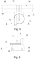
- Fig. 5 shows a top view of the bending unit 6 according to the second embodiment in a position mounted to the disc 40, in a configuration with the spacer disc 50 mounted on the drum conveyor 5.
- the working surface 30 of the drum conveyor is perpendicular to the front surface 3 which in this case is the front surface of the disc 40.
- Fig. 6 shows the bending unit 6 with the bending element 12 which is situated on a rotating ring 9 attached to the flange of a stub shaft 13.
- the ring 9 together with the bending element 12 perform a rotational movement about the rotational axis Y while the thrust element 11 remains stationary together with the stub shaft 13.
- the stub shaft 13 comprises a mounting flange 14 provided with mounting holes 15 for fixing with the screws 4' in the holes 4 made in the front surface 3 of the conveyor 5.
- Fig. 7 shows in side view of a section of the conveyor 5 of the apparatus 1 in another embodiment with the bending units 6 fixed to the front surface 3.
- the bending units 6 are fixed to the front surface 3 of the conveyor 5 by means of the screws 4' and the spacer plates 16.
- the thickness of the spacer plates 16 is selected accordingly so that the thrust element 11 is situated in an area 21 adapted for bending.
- the rotational axis Y of the bending element 12 is situated at an angle ⁇ 90° to the working surface 30 of the conveyor 5. Since the working surface 30 of the conveyor 5 is substantially a circle, the angle is measured exactly between the tangent of the circle defined by the working surface 30 at the point of intersection with the rotational axis Y of the bending mechanism 6.
- Fig.7 shows the process of bending the straw 2 by means of the bending element 12 which, by performing a rotational movement around its rotational axis Y , simultaneously bends the straw 2 in the area 21 around the thrust element 11.
- the other end of the straw 22 performs a movement over the straw 2 situated in the adjacent slot 10.
- Such a movement allows denser positioning of the slots 10 on the working surface 30 of the conveyor 5, thus allowing to increase the capacity of the apparatus 1. This is possible due to suitable angular positioning of the bending element, and more precisely of its rotational axis Y , with respect to the working surface 30.
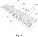
- Fig. 8 shows a section of the apparatus 1 in another embodiment wherein the conveyor 5 is a chain conveyor.
- the straws 2 are conveyed in the slots 10 on the working surface 30 of the conveyor 5 in parallel one next to another.
- the method of securing the straws 2 in the slots 10 is not shown. However, this can be carried out by means known to a specialist in the field, for example, with holding clamps or with a second conveyor moving parallel to the conveyor 5 which will hold the straws 2 from above during bending.
- the other end of the straw 22 is placed in the bending mechanism 6 which, by means of the supports 8, is attached to the front surface 3 of the conveyor 5.
- the bending element 12 makes a rotational movement around the axis Y , pushing on the other end 22 of the straw 2 and causing it to bend around the thrust element 11.
- the rotational movement of the bending element 12 is forced by a cam 17.
- an apparatus 1 for bending the straws 2 having the first end 20 and the second end 22 connected by the area 21 adapted for bending
- the apparatus comprising: the conveyor 5 for conveying the straws 2 provided with a plurality of slots 10 adapted for holding the first ends 21 of the straws 2, the slots 10 being arranged side by side on the working surface of the conveyor 30, the bending unit 6 provided with the thrust element 11 fixed stationary relative to the conveyor 5, the thrust element 11 determining the axis of bending of the straw 2, and the bending element 12 adapted for bending the straws around the thrust element 11.
- the apparatus 1 according to the invention is characterised in that the bending element 12 is attached on the front surface 3 of the conveyor 5, perpendicular to the working surface 30 of the conveyor 5.
- the conveyor 5 on which the bending unit 6 is mounted is a drum conveyor.
- the conveyor 5 is a belt/chain conveyor, substantially a linear conveyor.
- the bending element 12 of the bending mechanism 6 operates in a closed cycle.
- the path along which the bending elements 12 move at least partly coincides with the path of movement of the second ends 22 of the straws 2 on the conveyor.
- the bending element 12 makes a substantially rotational movement, also in all embodiments the axis Y of rotation of the bending element 12 is perpendicular to the working surface 30 of the conveyor 5. However, in other preferred embodiments, the axis Y of rotation of the bending element 12 is positioned at an angle other than 90 to the working surface 30 of the conveyor 5.
- the apparatus 1 has an adjusting unit 7 for changing the position of the bending mechanism 6 relative to the conveyor 5, the adjusting unit 7 being adapted for altering the position of the bending mechanism 6 relative to the front surface 30 of the conveyor 5.
- the slot 10 is adapted for holding the first end 21 of the straw 2 parallel to the working surface 30 of the conveyor 5, whereas the holder may allow the straw 2 to rotate around its own longitudinal axis or may be so tight that such rotation is prevented.
Landscapes
- Engineering & Computer Science (AREA)
- Mechanical Engineering (AREA)
- Shaping Of Tube Ends By Bending Or Straightening (AREA)
Priority Applications (1)
| Application Number | Priority Date | Filing Date | Title |
|---|---|---|---|
| EP23189119.3A EP4501587A1 (de) | 2023-08-02 | 2023-08-02 | Vorrichtung zum biegen von strohhalmen |
Applications Claiming Priority (1)
| Application Number | Priority Date | Filing Date | Title |
|---|---|---|---|
| EP23189119.3A EP4501587A1 (de) | 2023-08-02 | 2023-08-02 | Vorrichtung zum biegen von strohhalmen |
Publications (1)
| Publication Number | Publication Date |
|---|---|
| EP4501587A1 true EP4501587A1 (de) | 2025-02-05 |
Family
ID=88192344
Family Applications (1)
| Application Number | Title | Priority Date | Filing Date |
|---|---|---|---|
| EP23189119.3A Withdrawn EP4501587A1 (de) | 2023-08-02 | 2023-08-02 | Vorrichtung zum biegen von strohhalmen |
Country Status (1)
| Country | Link |
|---|---|
| EP (1) | EP4501587A1 (de) |
Citations (2)
| Publication number | Priority date | Publication date | Assignee | Title |
|---|---|---|---|---|
| WO2021250711A1 (en) | 2020-06-10 | 2021-12-16 | I.M.A. Industria Macchine Automatiche S.P.A. | Apparatus and method for bending tubular products |
| WO2022097041A1 (en) * | 2020-11-03 | 2022-05-12 | G.D Societa' Per Azioni | Method and unit to bend a straw |
-
2023
- 2023-08-02 EP EP23189119.3A patent/EP4501587A1/de not_active Withdrawn
Patent Citations (2)
| Publication number | Priority date | Publication date | Assignee | Title |
|---|---|---|---|---|
| WO2021250711A1 (en) | 2020-06-10 | 2021-12-16 | I.M.A. Industria Macchine Automatiche S.P.A. | Apparatus and method for bending tubular products |
| WO2022097041A1 (en) * | 2020-11-03 | 2022-05-12 | G.D Societa' Per Azioni | Method and unit to bend a straw |
Similar Documents
| Publication | Publication Date | Title |
|---|---|---|
| JP5766359B2 (ja) | カートン給紙システム | |
| JP4604002B2 (ja) | 包装材製造機の変換ステーション | |
| EP0412059A1 (de) | Einstellbares SternfÀ¶rderrad für runde und nicht runde Behälter | |
| EP1803668A1 (de) | Zuführvorrichtung mit einstellbarem Zeitzyklus und Verfahren | |
| US20140069253A1 (en) | Apparatus for Grooving Cardboard Cuttings | |
| EP1916188A1 (de) | Paketdruckeinheit | |
| JP6235047B2 (ja) | 廃物を切断して排出するための装置、カセット、ユニット、及びこれらを備えた機械 | |
| EP2042437A1 (de) | Etikettiervorrichtung | |
| EP4501587A1 (de) | Vorrichtung zum biegen von strohhalmen | |
| US6523331B1 (en) | Machine for setting heat-shrinkable sleeves on objects from a continuous sheath | |
| JP3627154B2 (ja) | 印刷物のトリミング装置 | |
| JPH01165429A (ja) | 板紙シート等の折曲げ装置 | |
| CN111615493B (zh) | 输送带组件 | |
| EP1935597B1 (de) | Gerät und Verfahren zur Entformung von Betonprodukten | |
| KR100377312B1 (ko) | 서로 접촉하고 있는 복수의 물품을 서로 분리하는 장치 | |
| JP5852466B2 (ja) | 製袋機 | |
| US7611181B2 (en) | Gripper head with rotatable gripper blades and anti-slant provision | |
| EP4501588A1 (de) | Verfahren und vorrichtung zum biegen von strohhalmnen | |
| JP2000184876A (ja) | 棒状の物体の周りにシ―トを巻くための装置 | |
| EP1504998A1 (de) | Etikettiervorrichtung | |
| CN110342191A (zh) | 传送带卡盘 | |
| WO1990002639A1 (en) | Apparatus for handling sheet material | |
| US12428236B2 (en) | Apparatus for loading and accumulating semi-finished plate-like pieces, in particular lenses | |
| US1300406A (en) | Conveying device. | |
| CN1109645C (zh) | 用于递送的拨纸器组件的移去装置及移去印刷材料的方法 |
Legal Events
| Date | Code | Title | Description |
|---|---|---|---|
| PUAI | Public reference made under article 153(3) epc to a published international application that has entered the european phase |
Free format text: ORIGINAL CODE: 0009012 |
|
| STAA | Information on the status of an ep patent application or granted ep patent |
Free format text: STATUS: THE APPLICATION HAS BEEN PUBLISHED |
|
| AK | Designated contracting states |
Kind code of ref document: A1 Designated state(s): AL AT BE BG CH CY CZ DE DK EE ES FI FR GB GR HR HU IE IS IT LI LT LU LV MC ME MK MT NL NO PL PT RO RS SE SI SK SM TR |
|
| STAA | Information on the status of an ep patent application or granted ep patent |
Free format text: STATUS: THE APPLICATION IS DEEMED TO BE WITHDRAWN |
|
| 18D | Application deemed to be withdrawn |
Effective date: 20250806 |