EP4501535A1 - Werkstückattraktionsvorrichtung - Google Patents
Werkstückattraktionsvorrichtung Download PDFInfo
- Publication number
- EP4501535A1 EP4501535A1 EP23780257.4A EP23780257A EP4501535A1 EP 4501535 A1 EP4501535 A1 EP 4501535A1 EP 23780257 A EP23780257 A EP 23780257A EP 4501535 A1 EP4501535 A1 EP 4501535A1
- Authority
- EP
- European Patent Office
- Prior art keywords
- workpiece
- attraction
- electrode
- separation body
- electrostatic
- Prior art date
- Legal status (The legal status is an assumption and is not a legal conclusion. Google has not performed a legal analysis and makes no representation as to the accuracy of the status listed.)
- Pending
Links
Images




Classifications
-
- B—PERFORMING OPERATIONS; TRANSPORTING
- B25—HAND TOOLS; PORTABLE POWER-DRIVEN TOOLS; MANIPULATORS
- B25J—MANIPULATORS; CHAMBERS PROVIDED WITH MANIPULATION DEVICES
- B25J15/00—Gripping heads and other end effectors
- B25J15/0085—Gripping heads and other end effectors with means for applying an electrostatic force on the object to be gripped
-
- H—ELECTRICITY
- H10—SEMICONDUCTOR DEVICES; ELECTRIC SOLID-STATE DEVICES NOT OTHERWISE PROVIDED FOR
- H10P—GENERIC PROCESSES OR APPARATUS FOR THE MANUFACTURE OR TREATMENT OF DEVICES COVERED BY CLASS H10
- H10P72/00—Handling or holding of wafers, substrates or devices during manufacture or treatment thereof
- H10P72/70—Handling or holding of wafers, substrates or devices during manufacture or treatment thereof for supporting or gripping
- H10P72/72—Handling or holding of wafers, substrates or devices during manufacture or treatment thereof for supporting or gripping using electrostatic chucks
- H10P72/722—Details of electrostatic chucks
-
- B—PERFORMING OPERATIONS; TRANSPORTING
- B65—CONVEYING; PACKING; STORING; HANDLING THIN OR FILAMENTARY MATERIAL
- B65H—HANDLING THIN OR FILAMENTARY MATERIAL, e.g. SHEETS, WEBS, CABLES
- B65H29/00—Delivering or advancing articles from machines; Advancing articles to or into piles
-
- H—ELECTRICITY
- H01—ELECTRIC ELEMENTS
- H01G—CAPACITORS; CAPACITORS, RECTIFIERS, DETECTORS, SWITCHING DEVICES, LIGHT-SENSITIVE OR TEMPERATURE-SENSITIVE DEVICES OF THE ELECTROLYTIC TYPE
- H01G7/00—Capacitors in which the capacitance is varied by non-mechanical means; Processes of their manufacture
- H01G7/02—Electrets, i.e. having a permanently-polarised dielectric
-
- H—ELECTRICITY
- H02—GENERATION; CONVERSION OR DISTRIBUTION OF ELECTRIC POWER
- H02N—ELECTRIC MACHINES NOT OTHERWISE PROVIDED FOR
- H02N13/00—Clutches or holding devices using electrostatic attraction, e.g. using Johnson-Rahbek effect
Definitions
- the present invention relates to a workpiece attraction device including an electrostatic attraction body that attracts a workpiece to a workpiece attraction surface, and a workpiece separation body that assists in separating the workpiece from the workpiece attraction surface after the attraction of the workpiece. More specifically, the present invention relates to a workpiece attraction device that can separate a workpiece in a short time and reliably from the workpiece attraction surface when dechucking the workpiece from the workpiece attraction surface.
- a method of applying a reverse voltage in dechucking a workpiece is known (see, for example, Patent Literature 1).
- a reverse voltage is applied that has the polarity opposite to that used in electrostatically attracting the workpiece to the electrostatic attraction body, and thereby the residual charge is reduced, enabling the workpiece to be separated smoothly.
- this method is susceptible to influence of the workpiece, and the reverse voltage to be applied varies depending on the material, physical properties, and surface conditions of the workpiece being transported, or the surrounding environment. This makes it difficult to actually eliminate the above-described transportation failures, and the like.
- a method in an example in which a charged plate is used that is charged by friction with a charging brush, a method is known that includes: providing a shutter, which can be opened and closed, between the charged plate and an adhesion plate for causing a workpiece to adhere to the lower surface thereof; and closing the shutter to block the adhesion force of the charged plate, in separating (dropping) the workpiece adhering to the lower surface of the adhesion plate (see Patent Literature 2).
- a transportation device that transports a handling target (workpiece) by attracting it to an electrostatic attraction plate having an electrode portion therein (see Patent Literature 3).
- the transportation device is provided with a release plate having an opening portion between the electrostatic attraction plate and the workpiece.
- the transportation device brings the release plate into close contact with the electrostatic attraction plate when attracting the workpiece, and the device separates the release plate from the electrostatic attraction plate when releasing (separating) the workpiece.
- the transportation device can reduce the electrostatic attraction force (workpiece attraction force) applied from the electrostatic attraction plate to the workpiece.
- the inventors have conducted extensive research into methods for preventing the effect of residual charge, and as a result, have made findings, which have led to the completion of the present invention, on a workpiece attraction device, the workpiece attraction device having a workpiece separation body, interposed between a workpiece and the electrostatic attraction body, to be able to assist in separation of the workpiece from the electrostatic attraction body after the attraction of the workpiece, the electrostatic attraction body having an attraction electrode therein to attract the workpiece.
- the findings indicate that the above-described failure can be eliminated by using a workpiece attraction device that prevents the workpiece separation body from dielectric polarization or electrostatic induction when attracting the workpiece.
- an object of the present invention is to provide a workpiece attraction device that can dechuck (separate) an attracted workpiece in a short time and reliably even when transporting thin workpieces such as paper, cloth, or resin films.
- the gist of the present invention is as follows.
- the workpiece attraction device of the present invention allows dechucking (separating) the attracted workpiece in a short time and reliably even when transporting thin workpieces such as paper, cloth, and resin films.
- the present invention can provide a workpiece attraction device that: prevents the workpiece separation body from dielectric polarization or electrostatic induction when attracting the workpiece; is therefore less susceptible to the influence of the type and shape of the workpiece or to the surrounding environment such as humidity; and is allowed to be versatile.
- the present invention is a workpiece attraction device, including: an electrostatic attraction body having an attraction electrode therein and a workpiece attraction surface capable of attracting a workpiece thereto by applying a voltage to the attraction electrode to generate a workpiece attraction force; and a workpiece separation body that is interposed between an attracted workpiece and the electrostatic attraction body, and assists in separating the workpiece from the workpiece attraction surface after application of voltage to the attraction electrode is stopped.
- the workpiece attraction device is designed to: prevent the workpiece separation body from dielectric polarization or electrostatic induction when applying a voltage to the attraction electrode to attract the workpiece; and eliminate the influence of residual charge, as much as possible, that remains after stopping the application of voltage to the attraction electrode.
- the workpiece separation body has a plurality of opening portions for applying the workpiece attraction force, generated on the workpiece attraction surface, toward the workpiece, and the workpiece separation body is partitioned into the opening portions by a lattice portion so that these opening portions are substantially uniformly present within a plane of the workpiece separation body.
- the present invention can specifically show the following embodiments. Depending on the material that constitutes the lattice portion of the workpiece separation body, either dielectric polarization or electrostatic induction can be used.
- the present invention is designed so that a bias in charge does not occur in the lattice portion of the workpiece separation body when a voltage is applied to the attraction electrode to attract the workpiece, and charge is not generated on the surface of the lattice portion, thereby eliminating residual charge as much as possible.
- a first embodiment is a workpiece attraction device having the attraction electrode of the electrostatic attraction body that does not face the lattice portion of the workpiece separation body, in a plan view from a workpiece side with a workpiece attracted.
- a plan view from a workpiece side with a workpiece attracted means a plan view from the workpiece side in a state in which the workpiece is attracted to the electrostatic attraction body, that is, in a state in which: a workpiece attraction force acts between the workpiece and the electrostatic attraction body; the workpiece is attracted to the electrostatic attraction body; and a workpiece separation body is interposed between the workpiece and the electrostatic attraction body in close contact with both.
- the plan view shows the relative positional relationship, in the state, between the attraction electrode of the electrostatic attraction body and the lattice portion of the workpiece separation body.
- examples of such a workpiece attraction device can include a device having a lattice portion of a workpiece separation body disposed so as to surround an attraction electrode of an electrostatic attraction body.
- FIG. 1 shows a specific example of this.
- the electrostatic attraction body 1 is provided with a bipolar attraction electrode 4 consisting of an attraction electrode 4a to which a positive voltage is applied and an attraction electrode 4b to which a negative voltage is applied.
- the workpiece separation body 5 has a plurality of opening portions 6 for applying the workpiece attraction force, generated on the workpiece attraction surface 1a of the electrostatic attraction body 1, to the workpiece w.
- the workpiece separation body 5 is partitioned into opening portions 6 by a lattice portion 7 so that opening portions 6 are substantially uniformly present within the plane of the workpiece separation body 5.
- the lattice portion 7 is formed by frame bodies 7a and a plurality of connecting portions 7b that connect the inside of the frame bodies 7a in the vertical direction.
- the connecting portions 7b extend in the length direction of the attraction electrodes 4a and 4b.
- the connecting portions 7b are each at a position corresponding to the gap between the adjacent attraction electrodes 4a and 4b.
- the frame bodies 7a are positioned outside the whole attraction electrode 4 consisting of the attraction electrodes 4a and 4b.
- the lattice portion 7 of the workpiece separation body 5 is disposed so as to surround the attraction electrode 4 of the electrostatic attraction body 1. Furthermore, the frame bodies 7a and connecting portions 7b do not overlap the attraction electrode 4 of the electrostatic attraction body 1 in the thickness direction of the workpiece attraction device, and in addition, the attraction electrode 4 of the electrostatic attraction body 1 do not face the lattice portion 7 of the workpiece separation body 5. Accordingly, when a voltage is applied to the attraction electrode, the lattice portion 7 of the workpiece separation body 5 is not directly above the attraction electrode 4 (4a, 4b). This prevents the lattice portion 7 of the workpiece separation body 5 from dielectric polarization or electrostatic induction. Therefore, even if the workpiece w is repeatedly attracted and separated (detached), no residual charge is accumulated. This can prevent the workpiece w from adhering to the workpiece separation body 5.
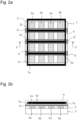
- a second embodiment can include a workpiece attraction device in which a conductive shielding member is interposed between a lattice portion of a workpiece separation body and an attraction electrode of an electrostatic attraction body.
- FIG 2 shows a specific example of the second embodiment.
- the electrostatic attraction body 1 in this example is provided with bipolar attraction electrodes 4a and 4b, similarly to the case of Figure 1 .
- the workpiece separation body 5 is provided with the opening portions 6 and the lattice portion 7 as in the case of Figure 1 .
- connecting portions 7b' forming the lattice portion 7 connect the inside of the frame bodies 7a in the horizontal direction, and the connecting portions 7b' cross the attraction electrodes 4a and 4b.
- conductive shielding members 8 are interposed between the connecting portions 7b' and the attraction electrodes 4a and 4b in the corresponding portions where the connecting portions 7b' cross the attraction electrodes 4a and 4b. Accordingly, the lattice portion 7 of the workpiece separation body 5 is not directly above the attraction electrode 4 (4a, 4b). This prevents the lattice portion 7 of the workpiece separation body 5 from dielectric polarization or electrostatic induction when a voltage is applied to the attraction electrode 4. This can then prevent the workpiece w from adhering to the workpiece separation body 5 as in the case of the first embodiment.
- the conductive shielding members 8 are preferably disposed on the electrostatic attraction body 1.
- the conductive shielding members 8 are left behind on the side of the electrostatic attraction body 1 when the workpiece separation body 5 separates from the workpiece attraction surface 1a of the electrostatic attraction body 1 to dechuck the workpiece w. This makes it possible to prevent the residual charge of the workpiece w from acting on the workpiece separation body 5 to cause the workpiece to adhere thereto.
- the conductive shielding members 8 are provided on the electrostatic attraction body 1, they may be disposed on the workpiece attraction surface 1a of the electrostatic attraction body 1, or they may be embedded inside the electrostatic attraction body 1.
- Figure 3 shows a workpiece attraction device according to a third embodiment in which the first embodiment and the second embodiment are combined.
- the connecting portions 7b forming the lattice portion 7 of the workpiece separation body 5 are located at positions corresponding to the gaps between the adjacent attraction electrodes 4a and 4b.
- the frame bodies 7a are positioned outside the whole attraction electrode 4 consisting of the attraction electrodes 4a and 4b.
- the connecting portions 7b and the frame bodies 7a do not overlap the attraction electrode 4 of the electrostatic attraction body 1 in the thickness direction of the workpiece attraction device.
- FIG 4 shows a workpiece attraction device according to a fourth embodiment, which is a modified example of the first embodiment.
- a plurality of electrostatic attraction bodies 1 are disposed on a support material 9, each electrostatic attraction body 1 having an attraction electrode 4 (4a, 4b) therein.
- the lattice portion 7 of the workpiece separation body 5 is formed of frame bodies 7a, connecting portions 7b that connect the inside of the frame bodies 7a in the vertical direction, and connecting portions 7b' that connect the inside of the frame bodies 7a in the horizontal direction.
- the frame bodies 7a and connecting portions 7b and 7b' do not overlap the attraction electrodes 4 of the electrostatic attraction bodies 1 in the thickness direction of the workpiece attraction device.
- each attraction electrode 4 of the electrostatic attraction body 1 does not face the lattice portion 7 of the workpiece separation body 5.
- the workpiece separation body in the present invention has a plurality of opening portions for applying the workpiece attraction force, generated on the workpiece attraction surface, toward the workpiece.
- the workpiece separation body is partitioned into these opening portions by the lattice portion so that they are substantially uniformly present within the plane of the workpiece separation body.
- the lattice portion of the workpiece separation body is formed of the frame bodies and the connecting portions that connect the inside of the frame bodies in the vertical direction and the connecting portions that connect the inside of the frame bodies in the horizontal direction.
- the lattice portion may be formed of only connecting portions crossing in the vertical and horizontal directions, without frame bodies.
- the angle at which the connecting portions cross may be set to any angle other than 90 degrees so that the connecting portions cross obliquely.
- the lattice portion of the workpiece separation body can be designed and formed as appropriate depending on the shape of the attraction electrode in the electrostatic attraction body, the size of the workpiece and the workpiece attraction surface, etc. The same applies to the opening portions of the workpiece separation body.
- the frame bodies may be formed of a material having a certain degree of rigidity, such as resin or metal, and within the frame bodies, the connecting portions may be formed using metal wires such as conductive wires, synthetic fibers such as nylon threads, wire materials such as ropes, threads, and filaments, as well as resins and tapes.
- a lattice portion 7 which is formed by stretching nylon threads, each having a diameter of about 100 ⁇ m, vertically and horizontally between the aluminum frame bodies 7a to make the connecting portions 7b; and as shown in Figure 5(b) , a connecting portion 7b made of resin, having opening portions 6, formed of a PET film of a thickness of about 50 ⁇ m may be prepared and attached to a frame body 7a as described above to form the lattice portion 7.
- the workpiece separation body is interposed between the attracted workpiece and the electrostatic attraction body, and assists in separating the workpiece from the workpiece attraction surface after the application of voltage to the attraction electrode is stopped. More specifically, when a workpiece is attracted, the workpiece separation body is in close contact with the electrostatic attraction body, as shown in Figures 1 to 4 . In contrast, in dechucking the workpiece, the workpiece separation body is moved relatively away from the electrostatic attraction body to assist in separation (dechuck) of the workpiece.
- a driving device such as a motor or an air cylinder may be used to move the whole workpiece separation body 5 away from the workpiece attraction surface 1a of the electrostatic attraction body 1 at a certain distance, so that the workpiece w may be separated from the workpiece attraction surface 1a.
- the workpiece separation body 5 may be tilted by a driving device (not shown) with a part thereof (one side thereof) fixed as an axis, so that the workpiece w may be separated from the workpiece attraction surface 1a. Thereafter, the workpiece separation body separates from the workpiece, thereby completing the separation of the workpiece.
- the workpiece separation body 5 may be accommodated in groove portions 10 formed in the gaps between the attraction electrodes 4 of the electrostatic attraction body 1 (the gaps between the attraction electrodes 4a and 4b) so that workpiece w may be in close contact with the workpiece attraction surface 1a. This makes it possible to prevent part of the workpiece attraction force generated by the electrostatic attraction body 1 from being lost (reduced) by the workpiece separation body 5.
- the electrostatic attraction body in the present invention may be any one that has an attraction electrode therein and can generate a workpiece attraction force by applying a voltage to the attraction electrode from the outside.
- a known device can be used in which an attraction electrode is provided between an upper insulation layer and a lower insulation layer, with the upper insulation layer side serving as a workpiece attraction surface.
- the upper insulation layer and the lower insulation layer can be formed using, for example, a resin film or a ceramic.
- the attraction electrode can be formed into a predetermined shape by using a metal foil such as copper or aluminum, forming a film through sputtering or ion plating, etc., etching a metal layer formed by spraying metal material or printing conductive ink, or the like.
- an electrostatic attraction body described in WO2020/027246A1 can be suitably used, for an electrostatic attraction body that can generate a strong workpiece attraction force on thin, sheet-shaped workpieces, having high insulation properties, such as paper, cloth, or resin films.
- a resin film having a volume resistivity of 1 ⁇ 10 10 to 1 ⁇ 10 13 ⁇ cm for the upper insulation layer. If the volume resistivity is within this range, a sufficient workpiece attraction force can be generated on the workpiece as described above. In particular, if the volume resistivity is less than 1 ⁇ 10 10 ⁇ cm, the attraction force itself for the workpiece is large, but leakage current may occur between the workpiece attraction surface and the workpiece, which causes some damage to the workpiece, such as paper or cloth.
- the resin film forming the upper insulation layer preferably has a tensile modulus of elasticity (Young's modulus) of 1 MPa or more and less than 100 MPa.
- the workpieces to be attracted in the present invention are often relatively thin and soft, as those described above.
- the resin film forming the upper insulation layer desirably has a tensile modulus of elasticity (Young's modulus) within the above range to be able to conform to and attract such workpieces. This is also advantageous in cases in which the upper insulation layer is curved to make the workpiece attraction surface curved.
- the thickness of the resin film is preferably 20 to 200 ⁇ m.
- Such resin films include polyimide, polyethylene terephthalate (PET), nylon, polypropylene, polyurethane, soft polyvinyl chloride, and polyvinylidene chloride. These may be processed by mixing fillers to adjust the properties such as electrical conductivity. Of these, in order to set the volume resistivity and tensile modulus of elasticity within the above-described range, polyurethane and soft polyvinyl chloride are preferable, and soft polyvinyl chloride is more preferable.
- the lower insulation layer may be made of the same resin film as described for the upper insulation layer, or may be made of a different insulation material. However, from the viewpoint of preventing the current that should flow between the workpiece and the upper insulation layer through the resin film that forms the upper insulation layer from flowing to the lower insulation layer side, it is preferable to use a lower insulation layer having a volume resistivity equal to or higher than that of the resin film forming the upper insulation layer. In addition, from the viewpoint of ensuring flexibility of the electrostatic attraction body as a whole, it is preferable that the lower insulation layer also has a tensile modulus of elasticity (Young's modulus) similar to that of the resin film forming the upper insulation layer. Furthermore, the thickness of the lower insulation layer is preferably 20 to 200 ⁇ m for the same reasons as in the case of the upper insulation layer.
- the insulation material for forming the lower insulation layer is not particularly limited. However, the same resin film as that forming the upper insulation layer, or a ceramic such as aluminum nitride or alumina may be used. Of these, preferred examples include polyimide, polyethylene terephthalate (PET), nylon, polypropylene, polyurethane, soft polyvinyl chloride, and polyvinylidene chloride as in the case of the resin film forming the upper insulation layer. These may be processed by mixing fillers to adjust the properties such as electrical conductivity.
- polyurethane or soft polyvinyl chloride is preferable, and soft polyvinyl chloride is even more preferable.
- attraction electrode Commonly known types of attraction electrode include bipolar electrode in which voltages of opposite polarity to each other are applied, and monopolar electrode in which a voltage is applied to the attraction electrode while the workpiece side is grounded. In the present invention, any of these can be used. However, since the monopolar electrode requires the workpiece side to be grounded as described above, it is preferable to employ a bipolar attraction electrode.
- the material for forming the attraction electrode is as described above. The thickness thereof is not particularly limited. However, taking into consideration the possibility of breakage due to deformation of the electrostatic attraction body, and conversely, the possibility of impaired flexibility due to an excessive thickness, the thickness of the attraction electrode is preferably 1 to 20 ⁇ m.
- examples of the bipolar attraction electrodes include a pair of attraction electrodes having a flat or semicircular shape, as well as a pair of attraction electrodes having a comb-tooth or mesh-like pattern.
- the attraction electrode When obtaining an electrostatic attraction body by using an upper insulation layer, a lower insulation layer, and an attraction electrode, the attraction electrode should be sandwiched between the upper insulation layer and the lower insulation layer so as not to be exposed.
- the layers may be integrally formed by thermocompression bonding, or the layers may be integrally formed using a bonding sheet, adhesive, pressure sensitive adhesive, etc.
- the conductive shielding member 8 may be disposed on the electrostatic attraction body 1.
- the conductive shielding member 8 may be attached to a predetermined position of an upper insulation layer 2 which forms the workpiece attraction surface 1a.
- the upper insulation layer 2 may be formed by a plurality of layers, so that the upper insulation layers 2 are integrated with the attraction electrode 4 and the lower insulation layer 3, with the conductive shielding member 8 being interposed between the upper insulation layers 2.
- the method for applying a voltage to the attraction electrode of the electrostatic attraction body is not particularly limited and any known method may be employed.
- a power supply device can be connected to the attraction electrode via a connection terminal, a switch, or the like.
- a power supply device capable of generating a high DC voltage may be suitably used.
- the potential difference to be generated can be about ⁇ 100 to ⁇ 5000 V.
- a boost circuit high voltage generating circuit
- the polarity of the voltage applied to the bipolar attraction electrode may be switched for each cycle of operation from attracting the workpiece to dechucking it.
- the workpieces to be attracted in the workpiece attraction device of the present invention is not particularly limited.
- the objects to be attracted include semiconductors and conductors, as well as sheet-shaped insulators such as paper, cloth, and resin films as described above, and workpieces such as bundles of fibers.
- a plurality of workpieces may be attracted and handled at once. For example, even if the workpiece is such an insulator that has a volume resistivity of about 1 ⁇ 10 12 to 1 ⁇ 10 14 ⁇ cm and has a thickness as thin as 2 mm or less, the influence of residual charge can be reduced as much as possible. Therefore, the workpiece can be used as a suitable workpiece in the present invention. In particular, even an extremely thin workpiece having a thickness of about 0.005 to 0.5 mm can be attracted and dechucked.
- a double-sided film tape was prepared that had a silicone adhesive on both sides of a 25 ⁇ m thick polyimide film protected with release paper (film separator), and a copper foil with a thickness of 18 ⁇ m was attached to the silicone adhesive on one side of the tape.
- the double-sided film tape had the following specification.
- Product name Double-coated adhesive Kapton (registered trademark) film tape, manufactured by Teraoka Seisakusho Co., Ltd.
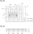
- only the copper foil portion was cut out using a cutting plotter (FC2250-180VC manufactured by Graphtec Corporation) to form an attraction electrode 24 consisting of a pair of comb-tooth electrodes 24a and 24b as shown in Figure 9(a) .
- the width (electrode width) of each of the comb-tooth portions of the comb-tooth electrodes 24a and 24b was 8 mm, and the interval (pitch) between the comb-tooth portions was 4 mm.
- a 5 mm thick plastic plate (low foaming PVC plate) was attached as a base material (support material) to the silicone adhesive on the other side of the double-sided film tape.
- the plastic plate had the following specification.
- soft polyvinyl chloride films each having a thickness of 100 ⁇ m were laid over the attraction electrode 24 formed on the double-sided film tape so as to cover the attraction electrode 24, and the films were attached together with a laminator and a roller.
- Each soft polyvinyl chloride film has a volume resistivity of 1 ⁇ 10 10 ⁇ cm and a tensile modulus of elasticity (Young's modulus) of 20 to 30 MPa.
- a voltage of ⁇ 1500 V was applied to the comb-tooth electrodes 24a and 24b of the test electrostatic attraction body obtained above from a power supply device (not shown), and the surface potential of the soft polyvinyl chloride film corresponding to the workpiece attraction surface was measured.
- a digital low potential measuring device KSD-3000 manufactured by Kasuga Denki, Inc. was used for the surface potential meter.
- the surface potential meter includes a vibration type surface potential sensor with a surface potential measurement area of 20 mm ⁇ 20 mm at the tip of the probe.
- the surface potential of the workpiece attraction surface of the target test electrostatic attraction body was measured at a measurement reference distance (height) of 10 mm.
- the surface potential of the workpiece attraction surface was measured at 3 mm intervals for the comb-tooth electrodes 24a and 24b in a direction perpendicularly crossing the longitudinal direction of the comb-tooth portions. Specifically, for four comb-tooth portions in a region Y enclosed by a dashed-dotted line in Figure 9(a) , the surface potential was measured at measurement points spaced 3 mm apart on a straight line P starting at P 1 and ending at P 15 .
- the comb-tooth portions of the negative comb-tooth electrode 24b and the comb-tooth portions of the positive comb-tooth electrode 24a are arranged alternately on a straight line P, with P 1 corresponding to the center of the electrode width of the comb-tooth portion of the comb-tooth electrode 24b.
- the surface potential was measured three times at one measurement point, and the average value was calculated.
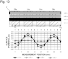
- the surface potential was measured along the straight line P, for the following four cases: ⁇ i> a case of measuring the surface potential of the workpiece attraction surface of the test electrostatic attraction body being as it is; ⁇ ii> a case of measuring the surface potential with a piece of aluminum foil, measuring 25 mm wide ⁇ 100 mm long ⁇ 20 ⁇ m thick, placed on the workpiece attraction surface; ⁇ iii> a case of measuring the surface potential with a polyester cloth (virtual workpiece), measuring 22 mm wide ⁇ 90 mm long, placed on the workpiece attraction surface; and ⁇ iv> a case of measuring the surface potential with the above-described aluminum foil placed on the workpiece attraction surface and with the above-described polyester cloth placed on top of the aluminum foil.
- the result is shown in Figure 10 . Note that when the aluminum foil was placed, it was connected to an earth.
- the surface potential does not increase even when a voltage is applied to the attraction electrodes, in the gaps between adjacent attraction electrodes or in places having a conductive shielding member such as aluminum foil; and therefore it is possible to prevent the workpiece or workpiece separation body from electrification in such positions.
- a test electrostatic attraction body was produced so as to have the aluminum foil, which was placed on the workpiece attraction surface in the previous example 1, embedded inside the electrostatic attraction body.
- a piece of aluminum foil having a width of 25 mm, a length of 100 mm, and a thickness of 20 ⁇ m was placed on the soft polyvinyl chloride film of the test electrostatic attraction body prepared in Example 1; the same soft polyvinyl chloride film having a thickness of 100 ⁇ m as that used in Example 1 was further laminated; and the resultant was attached together with a laminator and a roller.
- the aluminum foil was placed in a direction perpendicularly crossing the longitudinal direction of the comb-tooth portions of the comb-tooth electrodes 24a and 24b.
- a test electrostatic attraction body was produced, which had the above-described aluminum foil corresponding to the conductive shielding member, between two soft polyvinyl chloride films forming the upper insulation layer.
- This aluminum foil was also connected to an earth.
- the surface potential of the test electrostatic attraction body obtained in this manner was measured in the same manner as in Example 1, with the portion having the aluminum foil included in region Y. At that time, the surface potential was measured along the straight line P, for the following two cases: ⁇ v> a case of measuring the surface potential of the workpiece attraction surface in a portion that does not have aluminum foil; and ⁇ vi> a case of measuring the surface potential of the workpiece attraction surface in a portion that has aluminum foil. The result is shown in Figure 11 .
- the surface potential is highest at the widthwise center of the comb-tooth portion of each of comb-tooth electrodes 24a and 24b, and is smallest at the center of each gap between the adjacent comb-tooth portions.
- the surface potential did not increase even at the comb-tooth portions of the comb-tooth electrodes 24a and 24b, and remained at a value close to zero, showing the same results as in Example 1.
- the workpiece attraction device can prevent dielectric polarization and electrostatic induction of the workpiece separation body when attracting the workpiece. This makes it possible to dechuck (separate) the attracted workpiece in a short time and reliably.
- the present invention can eliminate the influence of residual charge on the workpiece or the workpiece separation body as much as possible. Therefore, the present invention can be used suitably when thin workpieces such as paper, cloth, and resin films are transported.
- a versatile workpiece attraction device can be provided that is less susceptible to the influence of the type and shape of the workpiece or to the surrounding environment such as humidity.
Landscapes
- Engineering & Computer Science (AREA)
- Mechanical Engineering (AREA)
- Power Engineering (AREA)
- Microelectronics & Electronic Packaging (AREA)
- Robotics (AREA)
- Sheets, Magazines, And Separation Thereof (AREA)
- Feeding Of Articles By Means Other Than Belts Or Rollers (AREA)
Applications Claiming Priority (2)
| Application Number | Priority Date | Filing Date | Title |
|---|---|---|---|
| JP2022053021 | 2022-03-29 | ||
| PCT/JP2023/012000 WO2023190247A1 (ja) | 2022-03-29 | 2023-03-24 | ワーク吸着装置 |
Publications (2)
| Publication Number | Publication Date |
|---|---|
| EP4501535A1 true EP4501535A1 (de) | 2025-02-05 |
| EP4501535A4 EP4501535A4 (de) | 2026-03-18 |
Family
ID=88201624
Family Applications (1)
| Application Number | Title | Priority Date | Filing Date |
|---|---|---|---|
| EP23780257.4A Pending EP4501535A4 (de) | 2022-03-29 | 2023-03-24 | Werkstückattraktionsvorrichtung |
Country Status (5)
| Country | Link |
|---|---|
| US (1) | US20250167029A1 (de) |
| EP (1) | EP4501535A4 (de) |
| JP (1) | JPWO2023190247A1 (de) |
| CN (1) | CN118946512A (de) |
| WO (1) | WO2023190247A1 (de) |
Family Cites Families (10)
| Publication number | Priority date | Publication date | Assignee | Title |
|---|---|---|---|---|
| JPS58207230A (ja) * | 1982-05-22 | 1983-12-02 | Koji Iizuka | シ−ト材の吸着法 |
| JPS5947190A (ja) * | 1982-09-06 | 1984-03-16 | 飯塚 孝司 | ハンドリング装置 |
| US6141203A (en) * | 1994-03-03 | 2000-10-31 | Sherman; Arthur | Electrostatic chuck |
| US5656093A (en) * | 1996-03-08 | 1997-08-12 | Applied Materials, Inc. | Wafer spacing mask for a substrate support chuck and method of fabricating same |
| KR100511854B1 (ko) * | 2002-06-18 | 2005-09-02 | 아네르바 가부시키가이샤 | 정전 흡착 장치 |
| JP2007045618A (ja) | 2005-08-12 | 2007-02-22 | Seiren Co Ltd | 静電吸着板を用いた搬送装置 |
| JP2008251737A (ja) * | 2007-03-29 | 2008-10-16 | Tomoegawa Paper Co Ltd | 静電チャック装置用電極部材ならびにそれを用いた静電チャック装置および静電吸着解除方法 |
| KR100942304B1 (ko) * | 2008-06-02 | 2010-02-16 | 주식회사 에이디피엔지니어링 | 기판척, 기판합착장치 |
| US8804299B2 (en) * | 2011-02-14 | 2014-08-12 | Applied Materials Israel, Ltd. | Electrostatic chuck and a method for supporting a wafer |
| TWI819046B (zh) | 2018-08-02 | 2023-10-21 | 日商創意科技股份有限公司 | 靜電吸附體 |
-
2023
- 2023-03-24 US US18/842,217 patent/US20250167029A1/en active Pending
- 2023-03-24 EP EP23780257.4A patent/EP4501535A4/de active Pending
- 2023-03-24 JP JP2024512410A patent/JPWO2023190247A1/ja active Pending
- 2023-03-24 CN CN202380030582.5A patent/CN118946512A/zh active Pending
- 2023-03-24 WO PCT/JP2023/012000 patent/WO2023190247A1/ja not_active Ceased
Also Published As
| Publication number | Publication date |
|---|---|
| TW202406669A (zh) | 2024-02-16 |
| EP4501535A4 (de) | 2026-03-18 |
| JPWO2023190247A1 (de) | 2023-10-05 |
| WO2023190247A1 (ja) | 2023-10-05 |
| CN118946512A (zh) | 2024-11-12 |
| US20250167029A1 (en) | 2025-05-22 |
Similar Documents
| Publication | Publication Date | Title |
|---|---|---|
| EP2548299B1 (de) | Materialien für elektroadhäsion und elektrolaminate | |
| EP2450948B1 (de) | Elektrostatisch anziehende struktur und herstellungsverfahren dafür | |
| WO2015095826A1 (en) | Modular electroadhesive gripping system | |
| US11866281B2 (en) | Electrostatic adsorption body | |
| US20230381791A1 (en) | Dust collector and dust collection method | |
| EP1295385B1 (de) | Elektro-adhäsions-vorrichtung | |
| EP4501535A1 (de) | Werkstückattraktionsvorrichtung | |
| JP2003282671A (ja) | 静電保持装置及びそれを用いた搬送装置 | |
| TWI922795B (zh) | 工件吸附裝置 | |
| JP2008112763A (ja) | 静電チャック | |
| US11718084B1 (en) | Object adhesion/peeling method, and object adhesion/peeling device | |
| HK40111645A (zh) | 工件吸附装置 | |
| CN118055808A (zh) | 电集尘器和使用其的集尘方法 | |
| CN106911989A (zh) | 静电换能器以及具有静电换能器的听筒 | |
| CN111433588B (zh) | 使用电磁体的电池部件剥离强度测量设备及使用该设备的剥离强度测量方法 | |
| Sindersberger et al. | Self-sensing electroadhesive polymer gripper with magnetically controllable surface geometry | |
| JP4419579B2 (ja) | 静電チャック | |
| JP4710333B2 (ja) | 仮接着シートおよびシートの仮接着方法ならびに仮接着済みシートつき基材。 | |
| JP2004136625A (ja) | 帯電防止用シート及び粘着テープ | |
| JP6343777B2 (ja) | 帯電装置 | |
| WO2026004469A1 (ja) | 静電チャック及びその製造方法 | |
| US20240083043A1 (en) | Electroadhesive pads, electroadhesive end effectors, and methods of producing the same | |
| US20070034957A1 (en) | Electrostatic foot for non-permanent attachment | |
| WO2024019100A1 (ja) | ガラス振動板及び振動子付きガラス振動板 | |
| HK40103917A (zh) | 电集尘器和使用其的集尘方法 |
Legal Events
| Date | Code | Title | Description |
|---|---|---|---|
| STAA | Information on the status of an ep patent application or granted ep patent |
Free format text: STATUS: THE INTERNATIONAL PUBLICATION HAS BEEN MADE |
|
| PUAI | Public reference made under article 153(3) epc to a published international application that has entered the european phase |
Free format text: ORIGINAL CODE: 0009012 |
|
| STAA | Information on the status of an ep patent application or granted ep patent |
Free format text: STATUS: REQUEST FOR EXAMINATION WAS MADE |
|
| 17P | Request for examination filed |
Effective date: 20241009 |
|
| AK | Designated contracting states |
Kind code of ref document: A1 Designated state(s): AL AT BE BG CH CY CZ DE DK EE ES FI FR GB GR HR HU IE IS IT LI LT LU LV MC ME MK MT NL NO PL PT RO RS SE SI SK SM TR |
|
| DAV | Request for validation of the european patent (deleted) | ||
| DAX | Request for extension of the european patent (deleted) | ||
| A4 | Supplementary search report drawn up and despatched |
Effective date: 20260217 |
|
| RIC1 | Information provided on ipc code assigned before grant |
Ipc: B23Q 7/04 20060101AFI20260211BHEP Ipc: B65H 5/00 20060101ALI20260211BHEP Ipc: H02N 13/00 20060101ALI20260211BHEP Ipc: B23Q 3/15 20060101ALI20260211BHEP Ipc: B25J 15/00 20060101ALI20260211BHEP Ipc: B65H 29/00 20060101ALI20260211BHEP Ipc: H01G 7/02 20060101ALI20260211BHEP Ipc: H10P 72/72 20260101ALI20260211BHEP |