EP4498533A1 - Winkelverbinder - Google Patents
Winkelverbinder Download PDFInfo
- Publication number
- EP4498533A1 EP4498533A1 EP24179855.2A EP24179855A EP4498533A1 EP 4498533 A1 EP4498533 A1 EP 4498533A1 EP 24179855 A EP24179855 A EP 24179855A EP 4498533 A1 EP4498533 A1 EP 4498533A1
- Authority
- EP
- European Patent Office
- Prior art keywords
- fitting
- contact
- press
- angle
- shell
- Prior art date
- Legal status (The legal status is an assumption and is not a legal conclusion. Google has not performed a legal analysis and makes no representation as to the accuracy of the status listed.)
- Granted
Links
Images




Classifications
-
- H—ELECTRICITY
- H01—ELECTRIC ELEMENTS
- H01R—ELECTRICALLY-CONDUCTIVE CONNECTIONS; STRUCTURAL ASSOCIATIONS OF A PLURALITY OF MUTUALLY-INSULATED ELECTRICAL CONNECTING ELEMENTS; COUPLING DEVICES; CURRENT COLLECTORS
- H01R12/00—Structural associations of a plurality of mutually-insulated electrical connecting elements, specially adapted for printed circuits, e.g. printed circuit boards [PCB], flat or ribbon cables, or like generally planar structures, e.g. terminal strips, terminal blocks; Coupling devices specially adapted for printed circuits, flat or ribbon cables, or like generally planar structures; Terminals specially adapted for contact with, or insertion into, printed circuits, flat or ribbon cables, or like generally planar structures
- H01R12/70—Coupling devices
- H01R12/71—Coupling devices for rigid printing circuits or like structures
- H01R12/72—Coupling devices for rigid printing circuits or like structures coupling with the edge of the rigid printed circuits or like structures
- H01R12/722—Coupling devices for rigid printing circuits or like structures coupling with the edge of the rigid printed circuits or like structures coupling devices mounted on the edge of the printed circuits
- H01R12/724—Coupling devices for rigid printing circuits or like structures coupling with the edge of the rigid printed circuits or like structures coupling devices mounted on the edge of the printed circuits containing contact members forming a right angle
-
- H—ELECTRICITY
- H01—ELECTRIC ELEMENTS
- H01R—ELECTRICALLY-CONDUCTIVE CONNECTIONS; STRUCTURAL ASSOCIATIONS OF A PLURALITY OF MUTUALLY-INSULATED ELECTRICAL CONNECTING ELEMENTS; COUPLING DEVICES; CURRENT COLLECTORS
- H01R13/00—Details of coupling devices of the kinds covered by groups H01R12/70 or H01R24/00 - H01R33/00
- H01R13/646—Details of coupling devices of the kinds covered by groups H01R12/70 or H01R24/00 - H01R33/00 specially adapted for high-frequency, e.g. structures providing an impedance match or phase match
- H01R13/6473—Impedance matching
- H01R13/6474—Impedance matching by variation of conductive properties, e.g. by dimension variations
-
- H—ELECTRICITY
- H01—ELECTRIC ELEMENTS
- H01R—ELECTRICALLY-CONDUCTIVE CONNECTIONS; STRUCTURAL ASSOCIATIONS OF A PLURALITY OF MUTUALLY-INSULATED ELECTRICAL CONNECTING ELEMENTS; COUPLING DEVICES; CURRENT COLLECTORS
- H01R13/00—Details of coupling devices of the kinds covered by groups H01R12/70 or H01R24/00 - H01R33/00
- H01R13/40—Securing contact members in or to a base or case; Insulating of contact members
-
- H—ELECTRICITY
- H01—ELECTRIC ELEMENTS
- H01R—ELECTRICALLY-CONDUCTIVE CONNECTIONS; STRUCTURAL ASSOCIATIONS OF A PLURALITY OF MUTUALLY-INSULATED ELECTRICAL CONNECTING ELEMENTS; COUPLING DEVICES; CURRENT COLLECTORS
- H01R13/00—Details of coupling devices of the kinds covered by groups H01R12/70 or H01R24/00 - H01R33/00
- H01R13/40—Securing contact members in or to a base or case; Insulating of contact members
- H01R13/42—Securing in a demountable manner
- H01R13/424—Securing in base or case composed of a plurality of insulating parts having at least one resilient insulating part
-
- H—ELECTRICITY
- H01—ELECTRIC ELEMENTS
- H01R—ELECTRICALLY-CONDUCTIVE CONNECTIONS; STRUCTURAL ASSOCIATIONS OF A PLURALITY OF MUTUALLY-INSULATED ELECTRICAL CONNECTING ELEMENTS; COUPLING DEVICES; CURRENT COLLECTORS
- H01R24/00—Two-part coupling devices, or either of their cooperating parts, characterised by their overall structure
- H01R24/28—Coupling parts carrying pins, blades or analogous contacts and secured only to wire or cable
-
- H—ELECTRICITY
- H01—ELECTRIC ELEMENTS
- H01R—ELECTRICALLY-CONDUCTIVE CONNECTIONS; STRUCTURAL ASSOCIATIONS OF A PLURALITY OF MUTUALLY-INSULATED ELECTRICAL CONNECTING ELEMENTS; COUPLING DEVICES; CURRENT COLLECTORS
- H01R24/00—Two-part coupling devices, or either of their cooperating parts, characterised by their overall structure
- H01R24/38—Two-part coupling devices, or either of their cooperating parts, characterised by their overall structure having concentrically or coaxially arranged contacts
- H01R24/40—Two-part coupling devices, or either of their cooperating parts, characterised by their overall structure having concentrically or coaxially arranged contacts specially adapted for high frequency
- H01R24/42—Two-part coupling devices, or either of their cooperating parts, characterised by their overall structure having concentrically or coaxially arranged contacts specially adapted for high frequency comprising impedance matching means or electrical components, e.g. filters or switches
- H01R24/44—Two-part coupling devices, or either of their cooperating parts, characterised by their overall structure having concentrically or coaxially arranged contacts specially adapted for high frequency comprising impedance matching means or electrical components, e.g. filters or switches comprising impedance matching means
-
- H—ELECTRICITY
- H01—ELECTRIC ELEMENTS
- H01R—ELECTRICALLY-CONDUCTIVE CONNECTIONS; STRUCTURAL ASSOCIATIONS OF A PLURALITY OF MUTUALLY-INSULATED ELECTRICAL CONNECTING ELEMENTS; COUPLING DEVICES; CURRENT COLLECTORS
- H01R24/00—Two-part coupling devices, or either of their cooperating parts, characterised by their overall structure
- H01R24/38—Two-part coupling devices, or either of their cooperating parts, characterised by their overall structure having concentrically or coaxially arranged contacts
- H01R24/40—Two-part coupling devices, or either of their cooperating parts, characterised by their overall structure having concentrically or coaxially arranged contacts specially adapted for high frequency
- H01R24/50—Two-part coupling devices, or either of their cooperating parts, characterised by their overall structure having concentrically or coaxially arranged contacts specially adapted for high frequency mounted on a PCB [Printed Circuit Board]
-
- H—ELECTRICITY
- H01—ELECTRIC ELEMENTS
- H01R—ELECTRICALLY-CONDUCTIVE CONNECTIONS; STRUCTURAL ASSOCIATIONS OF A PLURALITY OF MUTUALLY-INSULATED ELECTRICAL CONNECTING ELEMENTS; COUPLING DEVICES; CURRENT COLLECTORS
- H01R2103/00—Two poles
Definitions
- the present invention relates to an angle-type connector, particularly to a connector that is to be fitted to a counter connector along a fitting axis.
- JP 2023-77187 A discloses a so-called angle-type connector including an upper contact 1 and a lower contact 2 that are bent, as shown in FIG. 13 .
- the upper contact 1 and the lower contact 2 are accommodated in insulating and cylindrical housings 3 and 4, respectively.
- the housings 3 and 4 are accommodated in conductive and cylindrical shells 5 and 6, respectively.
- the angle-type connector is mounted on a substrate 7.
- the upper contact 1 is formed of a metal sheet having a substantially L shape and includes: a horizontally extending portion 1A linearly extending in a fitting direction in which the angle-type connector is fitted to a counter contact; a contacting portion 1B linearly extending frontward along the fitting direction from a tip of the horizontally extending portion 1A; a downwardly extending portion 1C linearly extending downward from a rear end of the horizontally extending portion 1A; and a mounting portion 1D protruding downward from a lower end of the downwardly extending portion 1C and to be connected to a corresponding circuit pattern of the substrate 7.
- the horizontally extending portion 1A is press-fitted into an insertion hole 3A of the housing 3 until the downwardly extending portion 1C abuts the housing 3, whereby the upper contact 1 is retained by the housing 3.
- the lower contact 2 includes: a horizontally extending portion 2A; a contacting portion 2B; a downwardly extending portion 2C; and a mounting portion 2D, and the horizontally extending portion 2A is press-fitted into an insertion hole 4A of the housing 4 until the downwardly extending portion 2C abuts the housing 4, whereby the lower contact 2 is retained by the housing 4.
- a bulging portion 1E and a bulging portion 2E that bulge rearward are formed in the downwardly extending portion 1C of the upper contact 1 and the downwardly extending portion 2C of the lower contact 2, respectively, thereby adjusting the characteristic impedance of the connector.
- the characteristic impedance of the connector can be adjusted by changing bulging lengths of the bulging portions 1E and 2E; when the bulging lengths of the bulging portions 1E and 2E that extend rearward increase, the characteristic impedance decreases, and conversely, when the bulging lengths of the bulging portions 1E and 2E decrease, the characteristic impedance increases.
- the bulging portions 1E and 2E formed to adjust the characteristic impedance of the connector are situated at positions displaced downward from the horizontally extending portions 1A and 2A, which are press-fitted into the insertion holes 3A and 4A of the housings 3 and 4, toward the mounting portions 1D and 2D, when the upper contact 1 and the lower contact 2 are pushed from the rear to the front with respect to the housings 3 and 4 by means of a tool for example, the upper contact 1 and the lower contact 2 become unstable in position, so that the upper contact 1 and the lower contact 2 are not easily press-fitted.
- the present invention has been made to overcome such a conventional problem and is aimed at providing an angle-type connector that can achieve both adjustment of characteristic impedance and facilitation of assembling.
- An angle-type connector according to the present invention is one to be fitted to a counter connector along a fitting axis, the angle-type connector comprising:
- FIG. 1 shows an angle-type coaxial connector 11 according to Embodiment 1 mounted on a substrate 21.
- the angle-type coaxial connector 11 is to be fitted to a counter connector (not shown) along a fitting axis C and includes one contact 12, an internal insulator 13 that surrounds the contact 12, a conductive shell 14 that surrounds the internal insulator 13, and an external insulator 15 that surrounds the shell 14.
- the external insulator 15 includes a counter connector accommodating portion 15A of recess shape in which part of a counter connector is to be inserted and accommodated when the angle-type coaxial connector 11 is fitted to the counter connector, and part of each of the contact 12, the internal insulator 13, and the shell 14 is exposed to the inside of the counter connector accommodating portion 15A.
- the angle-type coaxial connector 11 is mounted on the substrate 21 while the external insulator 15 is disposed on a surface of the substrate 21.
- the surface of the substrate 21 is defined as extending along an XY plane, the direction in which part of a counter connector (not shown) is inserted into the counter connector accommodating portion 15A of the external insulator 15 is referred to as "+Y direction,” and the direction perpendicular to the surface of the substrate 21 is referred to as "Z direction.”
- the Y direction is a direction in which the fitting axis C extends.
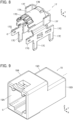
- FIG. 2 shows an assembly view of the angle-type coaxial connector 11.
- a first shell 16 is disposed on the +Y direction side of the external insulator 15
- the internal insulator 13 is disposed on the +Y direction side of the first shell 16
- the contact 12 is disposed on the +Y direction side of the internal insulator 13
- a second shell 17 is disposed on the +Y direction side of the contact 12.
- the internal insulator 13 and the external insulator 15 constitute an insulating housing 18 that retains the contact 12, while the first shell 16 and the second shell 17 constitute the conductive shell 14 that is retained by the housing 18 and surrounds the contact 12.
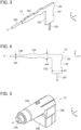
- the contact 12 is formed of a single metal sheet punched out in a substantially L shape and includes a press-fitting portion 12A linearly extending in the Y direction along the fitting axis C, a contacting portion 12B connected to a -Y directional tip of the press-fitting portion 12A, and a lead portion 12C connected to a +Y directional base end of the press-fitting portion 12A.
- the contacting portion 12B has a round columnar shape linearly extending from the tip end of the press-fitting portion 12A in the -Y direction along the fitting axis C.
- the lead portion 12C has a flat plate shape extending from the base end of the press-fitting portion 12A in the -Z direction orthogonal to the fitting axis C.
- the contact 12 further includes a mounting portion 12D of pin shape protruding in the -Z direction from a -Z directional tip of the lead portion 12C.
- A+Z directional and +Y directional end portion of the lead portion 12C is provided with a press-fitting force receiving surface 12E situated on the fitting axis C and facing in the +Y direction that is an opposite direction from the contacting portion 12B.
- the press-fitting force receiving surface 12E extends along an XZ plane orthogonal to the fitting axis C.
- the contact 12 is not formed by bending a metal sheet in an L shape but is formed of a metal sheet punched out in an L shape. Therefore, when a press-fitting force acting along the fitting axis C is applied to the press-fitting force receiving surface 12E situated on the fitting axis C, the contact 12 can be press-fitted into and retained by the housing 18. In order to allow the press-fitting force acting along the fitting axis C to be applied to the press-fitting force receiving surface 12E, it is desirable that the press-fitting force receiving surface 12E extends along an XZ plane orthogonal to the fitting axis C.
- the contact 12 includes an impedance adjusting portion 12F disposed between the press-fitting force receiving surface 12E of the lead portion 12C and the mounting portion 12D.
- the impedance adjusting portion 12F is formed by cutting out, in the -Y direction, a Z directional intermediate part of an end surface, facing in the +Y direction, of the lead portion 12C at a position away from the fitting axis C in the -Z direction orthogonal to the fitting axis C.
- the press-fitting force receiving surface 12E and the impedance adjusting portion 12F are disposed at positions different from each other in the Z direction orthogonal to the fitting axis C. Therefore, optimization of the shape of the press-fitting force receiving surface 12E for receiving a press-fitting force acting along the fitting axis C and optimization of the shape of the impedance adjusting portion 12F for matching characteristic impedance can be performed without interfering with each other.
- a width W 1 of the lead portion 12C in the Y direction orthogonal to the Z direction in which the lead portion 12C extends is set to be wider than a width W2 of the contacting portion 12B and a maximum width W3 of the press-fitting portion 12A in the Z direction orthogonal to the fitting axis C.
- the internal insulator 13 includes a tubular portion 13A extending along the fitting axis C, and an orthogonally extending portion 13B extending from a +Y directional part of the tubular portion 13A in the -Z direction orthogonal to the fitting axis C.
- the tubular portion 13A is provided with an insertion hole 13C which penetrates the internal insulator 13 along the fitting axis C and in which the press-fitting portion 12A of the contact 12 is to be inserted.
- the insertion hole 13C has a Z directional width slightly narrower than the maximum width W3 of the press-fitting portion 12A of the contact 12 shown in FIG. 4 .
- a lead portion accommodating portion 13D of recess shape communicating with the insertion hole 13C and opening in the +Y direction and the -Z direction is formed in a +Y directional part of the tubular portion 13A and the orthogonally extending portion 13B.
- the first shell 16 is formed of a single metal sheet being bent and includes a cylindrical portion 16A extending along the fitting axis C, and a front plate portion 16B extending in the -Z direction along an XZ plane from a +Y directional end portion of the cylindrical portion 16A.
- A+X directional end portion of the front plate portion 16B is bent in the -Y direction and forms a fixing portion 16C extending in the -Y direction along a YZ plane.
- a -X directional end portion thereof is bent in the -Y direction and forms another fixing portion 16C extending in the -Y direction along a YZ plane.
- the second shell 17 is formed of a single metal sheet being bent and includes a curved portion 17A that forms part of a cylinder taking the fitting axis C as its center, a rear plate portion 17B that extends along an XZ plane so as to cover a +Y directional end portion of the curved portion 17A, and a pair of lateral plate portions 17C that extend in the -Z direction along a YZ plane separately from a +X directional end portion and a -X directional portion of the curved portion 17A.
- a plurality of spring contacting portions 17D are formed to project on a -Y directional end portion of the curved portion 17A and extend in the -Y direction, while a plurality of shell mounting portions 17E are formed on a -Z directional end portion of each of the pair of lateral plate portions 17C to protrude in the -Z direction.
- a +X directional end portion and a -X directional end portion of the rear plate portion 17B are bent in the -Y direction and separately form fixing portions 17F extending in the -Y direction along a YZ plane.
- -Y directional end portions of the pair of lateral plate portions 17C separately form fixing portions 17G protruding in the -Y direction along a YZ plane.
- the contact 12 is moved in the -Y direction from the +Y direction toward the internal insulator 13, whereby the contact 12 is retained by the internal insulator 13.
- the contacting portion 12B and the press-fitting portion 12A of the contact 12 shown in FIG. 4 are inserted into the insertion hole 13C of the internal insulator 13 along the fitting axis C, and by means of a tool (not shown) for example, a force acting in the -Y direction is applied to the press-fitting force receiving surface 12E of the contact 12 situated on the fitting axis C, whereby the press-fitting portion 12A is press-fitted into the insertion hole 13C.
- the impedance adjusting portion 12F of the contact 12 does not bulge in the +Y direction from the end surface, facing in the +Y direction, of the lead portion 12C but is formed by cutting out, in the -Y direction, the Z directional intermediate part of the end surface, facing in the +Y direction, of the lead portion 12C. Therefore, without interference of the impedance adjusting portion 12F, a force acting in the -Y direction is applied to the press-fitting force receiving surface 12E by means of a tool (not shown), whereby the press-fitting portion 12A can be press-fitted into the insertion hole 13C.
- the press-fitting force receiving surface 12E of the contact 12 is situated on the fitting axis C and extends along an XZ plane orthogonal to the fitting axis C, by application of a force acting in the -Y direction to the press-fitting force receiving surface 12E, the press-fitting can be stably performed.
- the first shell 16 is moved in the -Y direction from the +Y direction toward the external insulator 15, and the fixing portion 16C of the first shell 16 shown in FIG. 7 is press-fitted into a fixed portion (not shown) inside the external insulator 15, whereby the first shell 16 is retained by the external insulator 15.
- the second shell 17 when the second shell 17 is moved from the +Y direction toward the - Y direction with respect to the first shell 16, the +Y directional part of the tubular portion 13A and the orthogonally extending portion 13B of the internal insulator 13 and a +Y directional end portion of the first shell 16 are covered with the second shell 17.
- the pair of fixing portions 17F and the pair of fixing portions 17G are press-fitted into the fixed portion (not shown) inside the external insulator 15, the second shell 17 is retained by the external insulator 15, whereby the assembling operation of the angle-type coaxial connector 11 is completed.
- FIG. 10 shows a perspective view of the thus-assembled angle-type coaxial connector 11 when viewed from an obliquely lower position.
- the lead portion 12C of the contact 12 is accommodated in the lead portion accommodating portion 13D of the internal insulator 13 and surrounded by the front plate portion 16B of the first shell 16 and the rear plate portion 17B and the pair of lateral plate portions 17C of the second shell 17.
- the mounting portion 12D of the contact 12 and the plurality of shell mounting portions 17E of the second shell 17 protrude from the external insulator 15 in the -Z direction.
- the contact 12 is surrounded by the cylindrical portion 16A and the front plate portion 16B of the first shell 16 and the curved portion 17A, the rear plate portion 17B, and the pair of lateral plate portions 17C shown in FIG. 10 of the second shell 17 with the press-fitting portion 12A being inserted in the insertion hole 13C of the internal insulator 13 and the lead portion 12C being accommodated in the lead portion accommodating portion 13D of the internal insulator 13.
- the plurality of spring contacting portions 17D elastically make contact with an outer peripheral surface of the cylindrical portion 16A of the first shell 16, whereby the second shell 17 is electrically connected to the first shell 16.
- the substrate 21 has a plurality of through-holes separately corresponding to the plurality of shell mounting portions 17E of the second shell 17, and each shell mounting portion 17E is passed through the corresponding through-hole of the substrate 21 and soldered, thereby being electrically connected to a ground layer (not shown) of the substrate 12 connected to the through hole.
- the lead portion 12C of the contact 12 includes the impedance adjusting portion 12F formed by cutting out the Z directional intermediate part of the end surface, facing in the +Y direction, of the lead portion 12C. Therefore, characteristic impedance in the lead portion 12C can be adjusted by selecting the Y directional depth and the Z directional length of the cutout in the impedance adjusting portion 12F, signal transmission characteristics can be improved, and high-speed transmission can be stably performed.
- the contact 12 is formed of a metal sheet punched out in an L shape, and includes the impedance adjusting portion 12F formed by cutting out, in the -Y direction, the end surface, facing in the +Y direction, of the lead portion 12C at a position away from the fitting axis C in the -Z direction. Therefore, without interference of the impedance adjusting portion 12F, the press-fitting portion 12A can be press-fitted into the insertion hole 13C of the internal insulator 13 by applying a press-fitting force acting along the fitting axis C to the press-fitting force receiving surface 12E situated on the fitting axis C, so that the angle-type coaxial connector 11 can be easily assembled.
- the press-fitting force receiving surface 12E and the impedance adjusting portion 12F of the contact 12 are disposed at positions different from each other in the Z direction orthogonal to the fitting axis C, optimization of the shape of the press-fitting force receiving surface 12E and optimization of the shape of the impedance adjusting portion 12F can be performed without interfering with each other.
- the angle-type coaxial connector 11 can be efficiently assembled.
- the housing 18 that retains the contact 12 is constituted of the two parts, i.e., the internal insulator 13 and the external insulator 15 in Embodiment 1 described above, the invention is not limited thereto, and the contact 12 can be retained by a housing constituted of a single part.
- the angle-type coaxial connector 11 can be efficiently assembled.
- the lead portion 12C of the contact 12 extends from the base end of the press-fitting portion 12A toward the -Z direction orthogonal to the fitting axis C in Embodiment 1 described above, the lead portion 12C is not limited to extending in the direction orthogonal to the fitting axis C, but it suffices if the lead portion 12C extends in a direction intersecting the fitting direction C.
- FIG. 12 shows an assembly view of an angle-type differential signal connector 31 according to Embodiment 2.
- a first shell 36 is disposed on the +Y direction side of an external insulator 35
- an internal insulator 33 is disposed on the +Y direction side of the first shell 36
- a pair of contacts 32 are disposed on the +Y direction side of the internal insulator 33
- a second shell 37 is disposed on the +Y direction side of the pair of contacts 32.
- the internal insulator 33 and the external insulator 35 constitute an insulating housing 38 that retains the pair of contacts 32, while the first shell 36 and the second shell 37 constitute a conductive shell 34 that is retained by the housing 38 and surrounds the pair of contacts 32.
- the pair of contacts 32 are used to transmit a differential signal and configured to be retained by the internal insulator 33 with a predetermined interval therebetween in the X direction.
- each of the pair of contacts 32 has the same structure as that of the contact 12 in Embodiment 1 shown in FIGS. 3 and 4 .
- the contact 32 is formed of a single metal sheet punched out in a substantially L shape and includes a press-fitting portion linearly extending in the Y direction along the fitting axis C, a contacting portion connected to a -Y directional tip of the press-fitting portion, a lead portion connected to a +Y directional base end of the press-fitting portion, and a mounting portion protruding in the -Z direction from a -Z directional tip of the lead portion.
- a +Y directional end portion of the lead portion of the contact 32 is provided with a press-fitting force receiving surface situated on the fitting axis C and facing in the +Y direction and an impedance adjusting portion situated away from the fitting axis C in the -Z direction and formed by cutting out the +Y directional end portion of the contact 32 in the -Y direction.
- the angle-type differential signal connector 31 When the angle-type differential signal connector 31 is assembled, as with the angle-type coaxial connector 11 of Embodiment 1, first, the pair of contacts 32 are retained by the internal insulator 33. Next, the first shell 36 is retained by the external insulator 35, and the internal insulator 33 that retains the pair of contacts 32 is covered with the first shell 36 and the second shell 37, whereby the angle-type differential signal connector 31 is assembled.
- each of the pair of contacts 32 includes, at the position away from the fitting axis C in the -Z direction, the impedance adjusting portion formed by cutting out the +Y directional end portion of the lead portion in the -Y direction, without interference of the impedance adjusting portion, the contact 32 can be press-fitted into and retained by the internal insulator 33 by applying a force acting along the fitting axis C to the press-fitting force receiving surface situated on the fixing axis C, so that the angle-type differential signal connector 31 can be easily assembled.
- the angle-type differential signal connector 31 that can achieve both adjustment of characteristic impedance and facilitation of assembling is configured.
- the shell 34 that surrounds the internal insulator 33 is constituted of the two parts, i.e., the first shell 36 and the second shell 37 also in Embodiment 2, the invention is not limited thereto, and also a shell constituted of a single part can surround the internal insulator 33.
- housing 38 that retains the pair of contacts 32 is composed of the two parts, i.e., the internal insulator 33 and the external insulator 35, the invention is not limited thereto, and the pair of contacts 32 can be retained by a housing constituted of a single part.
Landscapes
- Coupling Device And Connection With Printed Circuit (AREA)
- Details Of Connecting Devices For Male And Female Coupling (AREA)
- Connector Housings Or Holding Contact Members (AREA)
Applications Claiming Priority (1)
| Application Number | Priority Date | Filing Date | Title |
|---|---|---|---|
| JP2023123475A JP2025019718A (ja) | 2023-07-28 | 2023-07-28 | アングル型コネクタ |
Publications (2)
| Publication Number | Publication Date |
|---|---|
| EP4498533A1 true EP4498533A1 (de) | 2025-01-29 |
| EP4498533B1 EP4498533B1 (de) | 2025-08-20 |
Family
ID=91376481
Family Applications (1)
| Application Number | Title | Priority Date | Filing Date |
|---|---|---|---|
| EP24179855.2A Active EP4498533B1 (de) | 2023-07-28 | 2024-06-04 | Winkelverbinder |
Country Status (4)
| Country | Link |
|---|---|
| US (1) | US20250038441A1 (de) |
| EP (1) | EP4498533B1 (de) |
| JP (1) | JP2025019718A (de) |
| CN (1) | CN119447913A (de) |
Citations (2)
| Publication number | Priority date | Publication date | Assignee | Title |
|---|---|---|---|---|
| JP2013037928A (ja) * | 2011-08-09 | 2013-02-21 | Sumitomo Wiring Syst Ltd | 端子金具およびコネクタ |
| JP2023077187A (ja) | 2021-11-24 | 2023-06-05 | 矢崎総業株式会社 | 回路基板用のコネクタ、及び、回路基板用のコネクタの製造方法 |
-
2023
- 2023-07-28 JP JP2023123475A patent/JP2025019718A/ja active Pending
-
2024
- 2024-04-18 CN CN202410471767.6A patent/CN119447913A/zh active Pending
- 2024-06-04 EP EP24179855.2A patent/EP4498533B1/de active Active
- 2024-06-11 US US18/740,238 patent/US20250038441A1/en active Pending
Patent Citations (2)
| Publication number | Priority date | Publication date | Assignee | Title |
|---|---|---|---|---|
| JP2013037928A (ja) * | 2011-08-09 | 2013-02-21 | Sumitomo Wiring Syst Ltd | 端子金具およびコネクタ |
| JP2023077187A (ja) | 2021-11-24 | 2023-06-05 | 矢崎総業株式会社 | 回路基板用のコネクタ、及び、回路基板用のコネクタの製造方法 |
Also Published As
| Publication number | Publication date |
|---|---|
| CN119447913A (zh) | 2025-02-14 |
| US20250038441A1 (en) | 2025-01-30 |
| JP2025019718A (ja) | 2025-02-07 |
| EP4498533B1 (de) | 2025-08-20 |
Similar Documents
| Publication | Publication Date | Title |
|---|---|---|
| CN110061368B (zh) | 连接器 | |
| JP3082070B2 (ja) | 端子ソケット組立体 | |
| JP7623582B2 (ja) | 電気コネクタ | |
| JP2024093108A (ja) | 電気コネクタ | |
| JP3337650B2 (ja) | スイッチ付き同軸コネクタ | |
| US20240322467A1 (en) | Board connector and device | |
| EP2797180A1 (de) | Koaxialstecker mit Schalter | |
| US7445515B1 (en) | Audio jack | |
| CN115485568A (zh) | 高频测试接触元件和测试探针设备 | |
| US11799249B2 (en) | Electric connector with outer conductor connected to circuit board | |
| KR101910293B1 (ko) | 커넥터 | |
| EP4498533B1 (de) | Winkelverbinder | |
| EP3799218A1 (de) | Verbinder | |
| JP5712611B2 (ja) | 基板用コネクタ | |
| JP2019012635A (ja) | コネクタ | |
| EP4481957A1 (de) | Elektrischer verbinder | |
| JP6814031B2 (ja) | 同軸コネクタおよびコネクタ組立体 | |
| JP2024081319A (ja) | 電気コネクタ | |
| JP2023077187A (ja) | 回路基板用のコネクタ、及び、回路基板用のコネクタの製造方法 | |
| EP4546572A1 (de) | Substratverbinder, verfahren zur herstellung eines substratverbinders und endgerät | |
| JP2021082530A (ja) | 電気コネクタ及び電気コネクタの製造方法 | |
| US20260051696A1 (en) | Electrical connector | |
| US20260121310A1 (en) | Connector and connector assembly | |
| CN121312028A (zh) | 同轴连接器 | |
| JP2025003114A (ja) | 電気コネクタおよび電気コネクタのコンタクトピンの製造方法 |
Legal Events
| Date | Code | Title | Description |
|---|---|---|---|
| PUAI | Public reference made under article 153(3) epc to a published international application that has entered the european phase |
Free format text: ORIGINAL CODE: 0009012 |
|
| STAA | Information on the status of an ep patent application or granted ep patent |
Free format text: STATUS: REQUEST FOR EXAMINATION WAS MADE |
|
| 17P | Request for examination filed |
Effective date: 20240604 |
|
| AK | Designated contracting states |
Kind code of ref document: A1 Designated state(s): AL AT BE BG CH CY CZ DE DK EE ES FI FR GB GR HR HU IE IS IT LI LT LU LV MC ME MK MT NL NO PL PT RO RS SE SI SK SM TR |
|
| GRAP | Despatch of communication of intention to grant a patent |
Free format text: ORIGINAL CODE: EPIDOSNIGR1 |
|
| STAA | Information on the status of an ep patent application or granted ep patent |
Free format text: STATUS: GRANT OF PATENT IS INTENDED |
|
| RIC1 | Information provided on ipc code assigned before grant |
Ipc: H01R 12/72 20110101ALN20250416BHEP Ipc: H01R 24/50 20110101ALI20250416BHEP Ipc: H01R 24/44 20110101ALI20250416BHEP Ipc: H01R 13/6474 20110101AFI20250416BHEP |
|
| INTG | Intention to grant announced |
Effective date: 20250430 |
|
| GRAS | Grant fee paid |
Free format text: ORIGINAL CODE: EPIDOSNIGR3 |
|
| GRAA | (expected) grant |
Free format text: ORIGINAL CODE: 0009210 |
|
| STAA | Information on the status of an ep patent application or granted ep patent |
Free format text: STATUS: THE PATENT HAS BEEN GRANTED |
|
| AK | Designated contracting states |
Kind code of ref document: B1 Designated state(s): AL AT BE BG CH CY CZ DE DK EE ES FI FR GB GR HR HU IE IS IT LI LT LU LV MC ME MK MT NL NO PL PT RO RS SE SI SK SM TR |
|
| REG | Reference to a national code |
Ref country code: GB Ref legal event code: FG4D |
|
| REG | Reference to a national code |
Ref country code: CH Ref legal event code: EP |
|
| REG | Reference to a national code |
Ref country code: IE Ref legal event code: FG4D |
|
| REG | Reference to a national code |
Ref country code: DE Ref legal event code: R096 Ref document number: 602024000495 Country of ref document: DE |
|
| REG | Reference to a national code |
Ref country code: NL Ref legal event code: MP Effective date: 20250820 |
|
| PG25 | Lapsed in a contracting state [announced via postgrant information from national office to epo] |
Ref country code: IS Free format text: LAPSE BECAUSE OF FAILURE TO SUBMIT A TRANSLATION OF THE DESCRIPTION OR TO PAY THE FEE WITHIN THE PRESCRIBED TIME-LIMIT Effective date: 20251220 |
|
| PG25 | Lapsed in a contracting state [announced via postgrant information from national office to epo] |
Ref country code: NO Free format text: LAPSE BECAUSE OF FAILURE TO SUBMIT A TRANSLATION OF THE DESCRIPTION OR TO PAY THE FEE WITHIN THE PRESCRIBED TIME-LIMIT Effective date: 20251120 |
|
| REG | Reference to a national code |
Ref country code: LT Ref legal event code: MG9D |
|
| PG25 | Lapsed in a contracting state [announced via postgrant information from national office to epo] |
Ref country code: PT Free format text: LAPSE BECAUSE OF FAILURE TO SUBMIT A TRANSLATION OF THE DESCRIPTION OR TO PAY THE FEE WITHIN THE PRESCRIBED TIME-LIMIT Effective date: 20251222 |
|
| PG25 | Lapsed in a contracting state [announced via postgrant information from national office to epo] |
Ref country code: FI Free format text: LAPSE BECAUSE OF FAILURE TO SUBMIT A TRANSLATION OF THE DESCRIPTION OR TO PAY THE FEE WITHIN THE PRESCRIBED TIME-LIMIT Effective date: 20250820 |
|
| PG25 | Lapsed in a contracting state [announced via postgrant information from national office to epo] |
Ref country code: HR Free format text: LAPSE BECAUSE OF FAILURE TO SUBMIT A TRANSLATION OF THE DESCRIPTION OR TO PAY THE FEE WITHIN THE PRESCRIBED TIME-LIMIT Effective date: 20250820 Ref country code: NL Free format text: LAPSE BECAUSE OF FAILURE TO SUBMIT A TRANSLATION OF THE DESCRIPTION OR TO PAY THE FEE WITHIN THE PRESCRIBED TIME-LIMIT Effective date: 20250820 |
|
| PG25 | Lapsed in a contracting state [announced via postgrant information from national office to epo] |
Ref country code: GR Free format text: LAPSE BECAUSE OF FAILURE TO SUBMIT A TRANSLATION OF THE DESCRIPTION OR TO PAY THE FEE WITHIN THE PRESCRIBED TIME-LIMIT Effective date: 20251121 |
|
| PG25 | Lapsed in a contracting state [announced via postgrant information from national office to epo] |
Ref country code: SE Free format text: LAPSE BECAUSE OF FAILURE TO SUBMIT A TRANSLATION OF THE DESCRIPTION OR TO PAY THE FEE WITHIN THE PRESCRIBED TIME-LIMIT Effective date: 20250820 |
|
| PG25 | Lapsed in a contracting state [announced via postgrant information from national office to epo] |
Ref country code: LV Free format text: LAPSE BECAUSE OF FAILURE TO SUBMIT A TRANSLATION OF THE DESCRIPTION OR TO PAY THE FEE WITHIN THE PRESCRIBED TIME-LIMIT Effective date: 20250820 |
|
| PG25 | Lapsed in a contracting state [announced via postgrant information from national office to epo] |
Ref country code: PL Free format text: LAPSE BECAUSE OF FAILURE TO SUBMIT A TRANSLATION OF THE DESCRIPTION OR TO PAY THE FEE WITHIN THE PRESCRIBED TIME-LIMIT Effective date: 20250820 Ref country code: BG Free format text: LAPSE BECAUSE OF FAILURE TO SUBMIT A TRANSLATION OF THE DESCRIPTION OR TO PAY THE FEE WITHIN THE PRESCRIBED TIME-LIMIT Effective date: 20250820 |
|
| PG25 | Lapsed in a contracting state [announced via postgrant information from national office to epo] |
Ref country code: RS Free format text: LAPSE BECAUSE OF FAILURE TO SUBMIT A TRANSLATION OF THE DESCRIPTION OR TO PAY THE FEE WITHIN THE PRESCRIBED TIME-LIMIT Effective date: 20251120 |
|
| PG25 | Lapsed in a contracting state [announced via postgrant information from national office to epo] |
Ref country code: ES Free format text: LAPSE BECAUSE OF FAILURE TO SUBMIT A TRANSLATION OF THE DESCRIPTION OR TO PAY THE FEE WITHIN THE PRESCRIBED TIME-LIMIT Effective date: 20250820 |
|
| REG | Reference to a national code |
Ref country code: AT Ref legal event code: MK05 Ref document number: 1828394 Country of ref document: AT Kind code of ref document: T Effective date: 20250820 |
|
| PG25 | Lapsed in a contracting state [announced via postgrant information from national office to epo] |
Ref country code: SM Free format text: LAPSE BECAUSE OF FAILURE TO SUBMIT A TRANSLATION OF THE DESCRIPTION OR TO PAY THE FEE WITHIN THE PRESCRIBED TIME-LIMIT Effective date: 20250820 |
|
| PG25 | Lapsed in a contracting state [announced via postgrant information from national office to epo] |
Ref country code: DK Free format text: LAPSE BECAUSE OF FAILURE TO SUBMIT A TRANSLATION OF THE DESCRIPTION OR TO PAY THE FEE WITHIN THE PRESCRIBED TIME-LIMIT Effective date: 20250820 |
|
| PG25 | Lapsed in a contracting state [announced via postgrant information from national office to epo] |
Ref country code: AT Free format text: LAPSE BECAUSE OF FAILURE TO SUBMIT A TRANSLATION OF THE DESCRIPTION OR TO PAY THE FEE WITHIN THE PRESCRIBED TIME-LIMIT Effective date: 20250820 |
|
| PG25 | Lapsed in a contracting state [announced via postgrant information from national office to epo] |
Ref country code: IT Free format text: LAPSE BECAUSE OF FAILURE TO SUBMIT A TRANSLATION OF THE DESCRIPTION OR TO PAY THE FEE WITHIN THE PRESCRIBED TIME-LIMIT Effective date: 20250820 |
|
| PG25 | Lapsed in a contracting state [announced via postgrant information from national office to epo] |
Ref country code: CZ Free format text: LAPSE BECAUSE OF FAILURE TO SUBMIT A TRANSLATION OF THE DESCRIPTION OR TO PAY THE FEE WITHIN THE PRESCRIBED TIME-LIMIT Effective date: 20250820 |
|
| PG25 | Lapsed in a contracting state [announced via postgrant information from national office to epo] |
Ref country code: EE Free format text: LAPSE BECAUSE OF FAILURE TO SUBMIT A TRANSLATION OF THE DESCRIPTION OR TO PAY THE FEE WITHIN THE PRESCRIBED TIME-LIMIT Effective date: 20250820 Ref country code: SK Free format text: LAPSE BECAUSE OF FAILURE TO SUBMIT A TRANSLATION OF THE DESCRIPTION OR TO PAY THE FEE WITHIN THE PRESCRIBED TIME-LIMIT Effective date: 20250820 |