EP4498484A2 - Knopfzelle - Google Patents
Knopfzelle Download PDFInfo
- Publication number
- EP4498484A2 EP4498484A2 EP24188040.0A EP24188040A EP4498484A2 EP 4498484 A2 EP4498484 A2 EP 4498484A2 EP 24188040 A EP24188040 A EP 24188040A EP 4498484 A2 EP4498484 A2 EP 4498484A2
- Authority
- EP
- European Patent Office
- Prior art keywords
- plate
- main plate
- side edge
- button cell
- cap
- Prior art date
- Legal status (The legal status is an assumption and is not a legal conclusion. Google has not performed a legal analysis and makes no representation as to the accuracy of the status listed.)
- Pending
Links
Images


Classifications
-
- H—ELECTRICITY
- H01—ELECTRIC ELEMENTS
- H01M—PROCESSES OR MEANS, e.g. BATTERIES, FOR THE DIRECT CONVERSION OF CHEMICAL ENERGY INTO ELECTRICAL ENERGY
- H01M50/00—Constructional details or processes of manufacture of the non-active parts of electrochemical cells other than fuel cells, e.g. hybrid cells
- H01M50/10—Primary casings; Jackets or wrappings
- H01M50/183—Sealing members
- H01M50/186—Sealing members characterised by the disposition of the sealing members
-
- H—ELECTRICITY
- H01—ELECTRIC ELEMENTS
- H01M—PROCESSES OR MEANS, e.g. BATTERIES, FOR THE DIRECT CONVERSION OF CHEMICAL ENERGY INTO ELECTRICAL ENERGY
- H01M10/00—Secondary cells; Manufacture thereof
- H01M10/04—Construction or manufacture in general
- H01M10/0422—Cells or battery with cylindrical casing
- H01M10/0427—Button cells
-
- H—ELECTRICITY
- H01—ELECTRIC ELEMENTS
- H01M—PROCESSES OR MEANS, e.g. BATTERIES, FOR THE DIRECT CONVERSION OF CHEMICAL ENERGY INTO ELECTRICAL ENERGY
- H01M50/00—Constructional details or processes of manufacture of the non-active parts of electrochemical cells other than fuel cells, e.g. hybrid cells
- H01M50/10—Primary casings; Jackets or wrappings
- H01M50/102—Primary casings; Jackets or wrappings characterised by their shape or physical structure
- H01M50/109—Primary casings; Jackets or wrappings characterised by their shape or physical structure of button or coin shape
-
- H—ELECTRICITY
- H01—ELECTRIC ELEMENTS
- H01M—PROCESSES OR MEANS, e.g. BATTERIES, FOR THE DIRECT CONVERSION OF CHEMICAL ENERGY INTO ELECTRICAL ENERGY
- H01M50/00—Constructional details or processes of manufacture of the non-active parts of electrochemical cells other than fuel cells, e.g. hybrid cells
- H01M50/10—Primary casings; Jackets or wrappings
- H01M50/147—Lids or covers
- H01M50/148—Lids or covers characterised by their shape
- H01M50/153—Lids or covers characterised by their shape for button or coin cells
-
- H—ELECTRICITY
- H01—ELECTRIC ELEMENTS
- H01M—PROCESSES OR MEANS, e.g. BATTERIES, FOR THE DIRECT CONVERSION OF CHEMICAL ENERGY INTO ELECTRICAL ENERGY
- H01M50/00—Constructional details or processes of manufacture of the non-active parts of electrochemical cells other than fuel cells, e.g. hybrid cells
- H01M50/10—Primary casings; Jackets or wrappings
- H01M50/147—Lids or covers
- H01M50/155—Lids or covers characterised by the material
- H01M50/157—Inorganic material
- H01M50/159—Metals
-
- H—ELECTRICITY
- H01—ELECTRIC ELEMENTS
- H01M—PROCESSES OR MEANS, e.g. BATTERIES, FOR THE DIRECT CONVERSION OF CHEMICAL ENERGY INTO ELECTRICAL ENERGY
- H01M50/00—Constructional details or processes of manufacture of the non-active parts of electrochemical cells other than fuel cells, e.g. hybrid cells
- H01M50/10—Primary casings; Jackets or wrappings
- H01M50/172—Arrangements of electric connectors penetrating the casing
- H01M50/174—Arrangements of electric connectors penetrating the casing adapted for the shape of the cells
- H01M50/181—Arrangements of electric connectors penetrating the casing adapted for the shape of the cells for button or coin cells
-
- H—ELECTRICITY
- H01—ELECTRIC ELEMENTS
- H01M—PROCESSES OR MEANS, e.g. BATTERIES, FOR THE DIRECT CONVERSION OF CHEMICAL ENERGY INTO ELECTRICAL ENERGY
- H01M50/00—Constructional details or processes of manufacture of the non-active parts of electrochemical cells other than fuel cells, e.g. hybrid cells
- H01M50/10—Primary casings; Jackets or wrappings
- H01M50/183—Sealing members
- H01M50/184—Sealing members characterised by their shape or structure
-
- H—ELECTRICITY
- H01—ELECTRIC ELEMENTS
- H01M—PROCESSES OR MEANS, e.g. BATTERIES, FOR THE DIRECT CONVERSION OF CHEMICAL ENERGY INTO ELECTRICAL ENERGY
- H01M50/00—Constructional details or processes of manufacture of the non-active parts of electrochemical cells other than fuel cells, e.g. hybrid cells
- H01M50/10—Primary casings; Jackets or wrappings
- H01M50/183—Sealing members
- H01M50/186—Sealing members characterised by the disposition of the sealing members
- H01M50/188—Sealing members characterised by the disposition of the sealing members the sealing members being arranged between the lid and terminal
-
- H—ELECTRICITY
- H01—ELECTRIC ELEMENTS
- H01M—PROCESSES OR MEANS, e.g. BATTERIES, FOR THE DIRECT CONVERSION OF CHEMICAL ENERGY INTO ELECTRICAL ENERGY
- H01M50/00—Constructional details or processes of manufacture of the non-active parts of electrochemical cells other than fuel cells, e.g. hybrid cells
- H01M50/50—Current conducting connections for cells or batteries
- H01M50/528—Fixed electrical connections, i.e. not intended for disconnection
-
- H—ELECTRICITY
- H01—ELECTRIC ELEMENTS
- H01M—PROCESSES OR MEANS, e.g. BATTERIES, FOR THE DIRECT CONVERSION OF CHEMICAL ENERGY INTO ELECTRICAL ENERGY
- H01M50/00—Constructional details or processes of manufacture of the non-active parts of electrochemical cells other than fuel cells, e.g. hybrid cells
- H01M50/50—Current conducting connections for cells or batteries
- H01M50/531—Electrode connections inside a battery casing
-
- H—ELECTRICITY
- H01—ELECTRIC ELEMENTS
- H01M—PROCESSES OR MEANS, e.g. BATTERIES, FOR THE DIRECT CONVERSION OF CHEMICAL ENERGY INTO ELECTRICAL ENERGY
- H01M50/00—Constructional details or processes of manufacture of the non-active parts of electrochemical cells other than fuel cells, e.g. hybrid cells
- H01M50/50—Current conducting connections for cells or batteries
- H01M50/543—Terminals
- H01M50/552—Terminals characterised by their shape
- H01M50/559—Terminals adapted for cells having curved cross-section, e.g. round, elliptic or button cells
- H01M50/56—Cup shaped terminals
-
- H—ELECTRICITY
- H01—ELECTRIC ELEMENTS
- H01M—PROCESSES OR MEANS, e.g. BATTERIES, FOR THE DIRECT CONVERSION OF CHEMICAL ENERGY INTO ELECTRICAL ENERGY
- H01M50/00—Constructional details or processes of manufacture of the non-active parts of electrochemical cells other than fuel cells, e.g. hybrid cells
- H01M50/50—Current conducting connections for cells or batteries
- H01M50/543—Terminals
- H01M50/562—Terminals characterised by the material
-
- H—ELECTRICITY
- H01—ELECTRIC ELEMENTS
- H01M—PROCESSES OR MEANS, e.g. BATTERIES, FOR THE DIRECT CONVERSION OF CHEMICAL ENERGY INTO ELECTRICAL ENERGY
- H01M50/00—Constructional details or processes of manufacture of the non-active parts of electrochemical cells other than fuel cells, e.g. hybrid cells
- H01M50/50—Current conducting connections for cells or batteries
- H01M50/572—Means for preventing undesired use or discharge
- H01M50/584—Means for preventing undesired use or discharge for preventing incorrect connections inside or outside the batteries
- H01M50/59—Means for preventing undesired use or discharge for preventing incorrect connections inside or outside the batteries characterised by the protection means
- H01M50/593—Spacers; Insulating plates
-
- H—ELECTRICITY
- H01—ELECTRIC ELEMENTS
- H01M—PROCESSES OR MEANS, e.g. BATTERIES, FOR THE DIRECT CONVERSION OF CHEMICAL ENERGY INTO ELECTRICAL ENERGY
- H01M2220/00—Batteries for particular applications
- H01M2220/30—Batteries in portable systems, e.g. mobile phone, laptop
-
- Y—GENERAL TAGGING OF NEW TECHNOLOGICAL DEVELOPMENTS; GENERAL TAGGING OF CROSS-SECTIONAL TECHNOLOGIES SPANNING OVER SEVERAL SECTIONS OF THE IPC; TECHNICAL SUBJECTS COVERED BY FORMER USPC CROSS-REFERENCE ART COLLECTIONS [XRACs] AND DIGESTS
- Y02—TECHNOLOGIES OR APPLICATIONS FOR MITIGATION OR ADAPTATION AGAINST CLIMATE CHANGE
- Y02E—REDUCTION OF GREENHOUSE GAS [GHG] EMISSIONS, RELATED TO ENERGY GENERATION, TRANSMISSION OR DISTRIBUTION
- Y02E60/00—Enabling technologies; Technologies with a potential or indirect contribution to GHG emissions mitigation
- Y02E60/10—Energy storage using batteries
Definitions
- aspects of embodiments of the present disclosure relate to a button cell.
- a rechargeable battery is a battery that can be repeatedly charged and discharged.
- buttons cell which is a micro-sized rechargeable battery that may be mounted in a wearable device.
- a button cell may generally include an electrode assembly including a plurality of electrodes, a case for accommodating the electrode assembly and connected to one electrode of the electrode assembly, a cap plate coupled to the case and having the same polarity as that of the one electrode, and a terminal plate insulated from and bonded to the cap plate and connected to another electrode of the electrode assembly.
- One or more embodiments of the present disclosure may be directed to a button cell having a reduced thickness, may facilitate bonding between an electrode assembly and a terminal plate, and/or may have improved impact resistance.
- a button cell includes: an electrode assembly including a first electrode, a second electrode, and a separator between the first electrode and the second electrode; a case connected to the first electrode, the case accommodating the electrode assembly, and having an opening exposing the electrode assembly; a cap plate connected to the case to cover an outer boundary region of the opening, and the cap having a penetration hole exposing a central region of the opening; a terminal plate connected to the second electrode, the terminal plate is (e.g.
- the terminal plate includes a protrusion plate protruding from a rear surface of a main plate in a direction toward the electrode assembly, the main plate covering the penetration hole; and a bonding layer (disposed) between the cap plate and the main plate, and the bonding layer (e.g. electrically) insulating and bonding between the cap plate and the main plate.
- a front surface of the main plate and a front surface of the cap plate are located at the same plane as each other (e.g. they lie in the same plane).
- the terminal plate may be electrically insulated from the cap plate.
- the bonding layer may electrically insulate the cap plate from the main plate and bonds the cap plate with the main plate.
- the bonding layer may be or comprise an electrical insulator.
- the front surface of the main plate and the front surface of the cap plate may form an even surface.
- the electrode assembly may further include: a first electrode tab extending from the first electrode, and welded to the case; and a second electrode tab extending from the second electrode, and welded to the protrusion plate of the terminal plate.
- the protrusion plate may include the same material as that of the second electrode tab.
- the protrusion plate may include aluminum (Al).
- the protrusion plate may include the same material as that of the second electrode tab, and the protrusion plate may include aluminum (Al).
- the main plate may include a material different from that of the protrusion plate.
- the main plate may include a material different from that of the protrusion plate and the second electrode tab.
- the main plate may include the same material as that of the cap plate.
- the main plate may include a material different from that of the protrusion plate and the second electrode tab, and the main plate may include the same material as that of the cap plate.
- the main plate may be integral with the protrusion plate.
- the main plate may include the same material as that of the protrusion plate, and the protrusion plate may include the same material as that of the second electrode tab, and the main plate may be integral with the protrusion plate.
- the bonding layer may be located at the same height as those of the main plate and the cap plate from the electrode assembly. In other words, the front surface of the main plate and the front surface of the cap plate and the front surface of the bonding layer may form an even surface.
- the button cell may further include a rear surface insulation layer adjacent to the protrusion plate, and extending from the rear surface of the main plate to the rear surface of the cap plate via a rear surface of the bonding layer.
- a button cell may have a reduced thickness, may facilitate bonding between an electrode assembly and a terminal plate, and/or may have improved impact resistance.
- a specific process order may be different from the described order.
- two consecutively described processes may be performed at the same or substantially at the same time, or may be performed in an order opposite to the described order.
- first,” “second,” “third,” etc. may be used herein to describe various elements, components, regions, layers and/or sections, these elements, components, regions, layers and/or sections should not be limited by these terms. These terms are used to distinguish one element, component, region, layer or section from another element, component, region, layer or section. Thus, a first element, component, region, layer or section described below could be termed a second element, component, region, layer or section, without departing from the scope of the present disclosure.
- the expression "A and/or B” denotes A, B, or A and B. Expressions such as “at least one of,” when preceding a list of elements, modify the entire list of elements and do not modify the individual elements of the list. For example, the expression “at least one of a, b, or c,” “at least one of a, b, and c,” and “at least one selected from the group consisting of a, b, and c" indicates only a, only b, only c, both a and b, both a and c, both b and c, all of a, b, and c, or variations thereof.
- the term “substantially,” “about,” and similar terms are used as terms of approximation and not as terms of degree, and are intended to account for the inherent variations in measured or calculated values that would be recognized by those of ordinary skill in the art. Further, the use of “may” when describing embodiments of the present disclosure refers to “one or more embodiments of the present disclosure.” As used herein, the terms “use,” “using,” and “used” may be considered synonymous with the terms “utilize,” “utilizing,” and “utilized,” respectively.
- a button cell according to one or more embodiments will first be described with reference to FIG. 1 through FIG. 5 .
- a button cell may include a coin cell, which may be an ultra-small rechargeable battery, but the present disclosure is not limited thereto, and may include a cylindrical or pin-type battery.
- the button cell may be a battery in a thin coin or button shape, and may mean a battery having a ratio of a height to a diameter that is 1 or less, but the present disclosure is not limited thereto.
- Button cells are typically cylindrical, such that a cross-section in a horizontal direction is circular, but the present disclosure is not limited thereto, and a cross-section in the horizontal direction may be in an elliptical shape or a polygonal shape.
- the diameter may mean a maximum distance in the horizontal direction of the battery
- the height may mean a maximum distance (e.g., a distance from a flat bottom surface to a flat top surface) in a vertical direction of the battery.
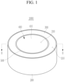
- FIG. 1 is a perspective view illustrating a button cell according to an embodiment.
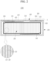
- FIG. 2 is a cross-sectional view taken along the line II-II of FIG. 1 .
- a button cell 1000 may be a rechargeable battery that can be repeatedly charged and discharged.
- the button cell 1000 may include an electrode assembly 100, a case 200, a cap plate 300, a terminal plate 400, a bonding layer 500, and a rear surface insulation layer 600.
- the electrode assembly 100 is accommodated in the case 200.
- a lower portion of the electrode assembly 100 faces a bottom portion of the case 200, and an upper portion of the electrode assembly 100 faces the cap plate 300 covering an opening 210 of the case 200, the terminal plate 400, and the bonding layer 500.
- the upper and lower portions of the electrode assembly 100 may have a planar shape that is parallel or substantially parallel to each other, but the present disclosure is not limited thereto.
- the electrode assembly 100 includes a first electrode 110, a second electrode 120, a separator 130, a first electrode tab 140, and a second electrode tab 150.
- the first electrode 110 and the second electrode 120 are spaced apart from each other, and the separator 130 including an insulating material is positioned between the first electrode 110 and the second electrode 120.
- the first electrode 110 may be an anode
- the second electrode 120 may be a cathode, but the present disclosure is not limited thereto.
- the first electrode 110 may be the cathode
- the second electrode 120 may be the anode.
- the first electrode 110 has a band shape extending in one direction.
- the first electrode 110 may include an anode coating portion, which is a region where an anode active material layer is applied to a current collector of a metal foil (e.g., a Cu foil), and an anode uncoated portion, which is a region where an active material is not applied.
- the anode uncoated portion may be positioned at one end portion in an extending direction of the first electrode 110.
- the second electrode 120 has a band shape spaced apart from the first electrode 110 with the separator 130 interposed therebetween, and extending in one direction.
- the second electrode 120 may include a cathode coating portion, which is a region where a cathode active material layer is applied to a current collector of a metal foil (e.g., an aluminum foil), and a cathode uncoated portion, which is a region where an active material is not applied.
- the cathode uncoated portion may be positioned at one end portion in an extending direction of the second electrode 120.
- the separator 130 extends in one direction between the first electrode 110 and the second electrode 120, to prevent short circuit between the first electrode 110 and the second electrode 120.
- the first electrode 110, the separator 130, and the second electrode 120 are sequentially stacked and wound in a jelly roll shape, but the present disclosure is not limited thereto, and may be formed in various suitable shapes.
- Each of the first electrode 110, the second electrode 120, and the separator 130 may include various suitable materials.
- the first electrode tab 140 extends from the first electrode 110 of the electrode assembly 100 to the case 200.
- the first electrode tab 140 is connected to (e.g., attached to or coupled to) the bottom portion of the case 200, and connects the first electrode 110 and the case 200 to each other.
- the first electrode tab 140 contacts the first electrode 110 and the case 200.
- the first electrode tab 140 may be welded to the bottom portion of the case 200, but the present disclosure is not limited thereto, and the first electrode tab 140 may contact the bottom portion of the case 200.
- the case 200 and the cap plate 300 may have the same polarity as that of the first electrode 110.
- the second electrode tab 150 extends from the second electrode 120 of the electrode assembly 100 to the terminal plate 400.
- the second electrode tab 150 may be connected to (e.g., attached to or coupled to) a protrusion plate 420 of the terminal plate 400, and connects the second electrode 120 and the terminal plate 400 to each other.
- the second electrode tab 150 contacts the second electrode 120 and the terminal plate 400.
- the second electrode tab 150 may be welded to a surface of the protrusion plate 420 of the terminal plate 400, but the present disclosure is not limited thereto, and may be in contact with the surface of the protrusion plate 420.
- the terminal plate 400 may have the same polarity as that of the second electrode 120.
- a center pin penetrating a center of the electrode assembly 100 in the vertical direction may be positioned in a central portion of the electrode assembly 100.
- the center pin may support the first electrode tab 140 and the second electrode tab 150, but the present disclosure is not limited thereto.
- the case 200 is connected to the first electrode 110 of the electrode assembly 100, and accommodates the electrode assembly 100.
- the case 200 includes the opening 210 exposing the upper portion of the electrode assembly 100.
- the bottom portion of the case 200 may be welded to the first electrode tab 140 and connected to the first electrode 110 of the electrode assembly 100, and accordingly, the case 200 may have the same polarity as that of the first electrode 110.
- the case 200 may have a can shape in a cylindrical shape for accommodating the electrode assembly 100 of a jelly roll shape, but the present disclosure is not limited thereto, and may have various suitable shapes.
- the case 200 may accommodate various suitable electrolyte solutions together with the electrode assembly 100.
- An exterior surface of the case 200 and an exterior surface of the cap plate 300 may be the first electrode terminal of the button cell 1000, but the present disclosure is not limited thereto.
- An upper surface of a main plate 410, which is an exterior surface of the terminal plate 400, may be the second electrode terminal of the button cell 1000, but the present disclosure is not limited thereto.
- a plated layer may be coated on the exterior surface of the case 200, but the present disclosure is not limited thereto, and various suitable coating layers may be coated on the exterior surface of the case 200.
- the case 200 may include stainless steel, but the present disclosure is not limited thereto, and may include various known metals.
- the opening 210 of the case 200 may be covered by the cap plate 300, the terminal plate 400, and the bonding layer 500.
- FIG. 3 is an enlarged view of the portion A of FIG. 2 .
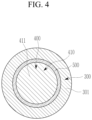
- the cap plate 300 is coupled to the case 200, and covers an outer boundary region of the opening 210.
- the cap plate 300 includes a penetration hole 310 exposing a central region of the opening 210.
- the cap plate 300 may be directly coupled to a sidewall of the case 200 forming the opening 210 of the case 200 by welding or the like, and covers the outer boundary region of the opening 210.
- the cap plate 300 has a ring shape by the centrally formed penetration hole 310 in a plan view, but the present disclosure is not limited thereto.
- the cap plate 300 is coupled to the case 200, and has the same polarity as that of the first electrode 110. Accordingly, the cap plate 300 and the case 200 may have the same polarity as that of the first electrode 110.
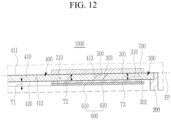
- a button cell 1006 may include an electrode assembly, the case 200, the cap plate 300, the terminal plate 400, the bonding layer 500, the rear surface insulation layer 600, and the front surface insulation layer 700.
- the front surface 411 of the main plate 410 of the terminal plate 400 may be the second electrode terminal of the button cell 1006, and the rear surface 412 of the main plate 410 contacts the protrusion plate 420.
- the main plate 410 is insulated from and bonded to the cap plate 300 by the bonding layer 500.
- the outer side edge 413 of the main plate 410 faces the inner side edge 303 of the cap plate 300 forming the penetration hole 310 of the cap plate 300, thereby interposing the bonding layer 500 therebetween.
- the outer side edge 413 of the main plate 410 is bonded to the inner side edge 303 of the cap plate 300 by the bonding layer 500.
- the outer side edge 413 of the main plate 410 may have a reverse inclined shape
- the inner side edge 303 of the cap plate 300 may have a forward inclined shape
- the reverse inclined shape of the outer side edge 413 of the main plate 410 and the forward inclined shape of the inner side edge 303 of the cap plate 300 may be longitudinal cross-sectional forms, but the present disclosure is not limited thereto, and may be a transverse cross-sectional form or a cross-sectional form according to an imaginary straight line or an imaginary surface.
- the bonding area between the bonding layer 500 and the main plate 410 of the terminal plate 400 as well as the bonding area between the bonding layer 500 and the cap plate 300 may be increased. Therefore, the bonding strength between the main plate 410 and the cap plate 300 may be improved, and impact resistance of the button cell 1006 may be improved.
- the front surface 411 of the main plate 410 is positioned at (e.g., in or on) the same plane FP as that of the front surface 301 of the cap plate 300.
- the front surface of the main plate 410, the front surface 301 of the cap plate 300, and the front surface of the bonding layer 500 may be positioned at (e.g., in or on) the same plane FP as each other. Because the front surface 411 of the main plate 410 and the front surface 301 of the cap plate 300 are positioned at (e.g., in or on) the same plane FP as each other, a thickness of the button cell 1006 may be formed to be thinner.
- the front surface insulation layer 700 is positioned on the front surface 411 of the main plate 410, and may correspond to (e.g., overlap with) the rear surface insulation layer 600.
- the front surface insulation layer 700 extends from the front surface 411 of the main plate 410 to the front surface 301 of the cap plate 300 via the front surface of the bonding layer 500, and may correspond to the rear surface insulation layer 600.
- the front surface insulation layer 700 may include one layer or a plurality of layers. Because the front surface insulation layer 700 extends from the portion of the front surface 411 of the main plate 410 to the front surface of the cap plate 300, the main plate 410 and the cap plate 300 may be prevented from being short circuited with each other.
- the main plate 410 of the terminal plate 400 includes a different material from that of the protrusion plate 420
- the main plate 410 may include a material having a larger strength compared to that of the material of the protrusion plate 420
- the protrusion plate 420 may include the same material as that of the second electrode tab 150 of the electrode assembly, by which bonding between the electrode assembly and the terminal plate 400 may be facilitated, and impact resistance of the button cell 1006 may be improved.
- the first thickness T1 of the protrusion plate 420 may be thinner than the second thickness T2 of the main plate 410, the third thickness T3 of the cap plate 300, and the thickness of the bonding layer 500, the distance from the electrode assembly to the terminal plate 400 may be minimized or reduced, and therefore, the thickness of the button cell 1006 may be formed to be thinner.
- the bonding layer 500 includes polypropylene resin or the like having an elasticity compared to that of ceramic or brittle glass, and bond the cap plate 300 and the main plate 410 to each other at the same height as those of the main plate 410 and the cap plate 300, separating the bonding layer 500 from between the main plate 410 and the cap plate 300 by external impacts may be suppressed, and accordingly, impact resistance of the button cell 1006 may be improved.
- the bonding area between the cap plate 300 and the main plate 410 of the terminal plate 400 may be increased, the bonding strength between the main plate 410 and the cap plate 300 may be improved, and impact resistance of the button cell 1006 may be improved.
- the button cell 1006 having a reduced thickness, facilitating bonding between the electrode assembly and the terminal plate 400, and improving impact resistance may be provided.
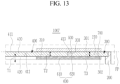
- buttons cell according to another embodiment will be described with reference to FIG. 13 .
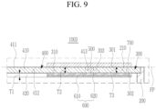
- FIG. 13 is a cross-sectional view illustrating a portion of a button cell according to another embodiment.
- a button cell 1007 may include an electrode assembly, the case 200, the cap plate 300, the terminal plate 400, the bonding layer 500, the rear surface insulation layer 600, and the front surface insulation layer 700.
- the front surface 411 of the main plate 410 of the terminal plate 400 may be the second electrode terminal of the button cell 1007, and the rear surface 412 of the main plate 410 contacts the protrusion plate 420.
- the main plate 410 is insulated from and bonded to the cap plate 300 by the bonding layer 500.
- the outer side edge 413 of the main plate 410 faces the inner side edge 303 of the cap plate 300 forming the penetration hole 310 of the cap plate 300, thereby interposing the bonding layer 500 therebetween.
- the outer side edge 413 of the main plate 410 is bonded to the inner side edge 303 of the cap plate 300 by the bonding layer 500.
- the outer side edge 413 of the main plate 410 may have protrusions and depressions
- the inner side edge 303 of the cap plate 300 may have protrusions and depressions.
- the protrusions and depressions of the outer side edge 413 of the main plate 410 and the protrusions and depressions of the inner side edge 303 of the cap plate 300 may be longitudinal cross-sectional forms, but the present disclosure is not limited thereto, and may be a transverse cross-sectional form or a cross-sectional form according to an imaginary straight line or an imaginary surface.
- the bonding area between the bonding layer 500 and the main plate 410 of the terminal plate 400 as well as the bonding area between the bonding layer 500 and the cap plate 300 may be increased. Therefore, the bonding strength between the main plate 410 and the cap plate 300 may be improved, and impact resistance of the button cell 1007 may be improved.
- the front surface 411 of the main plate 410 is positioned at (e.g., in or on) the same plane FP as that of the front surface 301 of the cap plate 300.
- the front surface of the main plate 410, the front surface 301 of the cap plate 300, and the front surface of the bonding layer 500 may be positioned at (e.g., in or on) the same plane FP as each other. Because the front surface 411 of the main plate 410 and the front surface 301 of the cap plate 300 may be positioned at (e.g., in or on) the same plane FP as each other, a thickness of the button cell 1007 may be formed to be thinner.
- the bonding layer 500 may be positioned at the same or substantially the same height as those of the main plate 410 and the cap plate 300 from the electrode assembly between the main plate 410 of the terminal plate 400 and the cap plate 300.
- the bonding layer 500 is positioned between the outer side edge 413 of the main plate 410 and the inner side edge 303 of the cap plate 300 forming the penetration hole 310, and the bonding layer 500 bonds between the inner side edge 303 of the cap plate 300 and the outer side edge 413 of the main plate 410.
- the bonding layer 500 may be positioned inside the penetration hole 310 of the cap plate 300.
- the bonding layer 500 may be positioned completely inside the penetration hole 310 of the cap plate 300.
- the bonding layer 500 has a ring shape in a plan view, but the present disclosure is not limited thereto.
- the bonding layer 500 may have a cross-sectional form corresponding to at least one cross-sectional form from among the inner side edge 303 of the cap plate 300 and/or the outer side edge 413 of the main plate 410.
- the bonding layer 500 may have a planar shape corresponding to at least one planar shape from among the inner side edge 303 of the cap plate 300 and/or the outer side edge 413 of the main plate 410.
- the front surface insulation layer 700 is positioned on the front surface 411 of the main plate 410, and may correspond to (e.g., overlap with) the rear surface insulation layer 600.
- the front surface insulation layer 700 extends from the front surface 411 of the main plate 410 to the front surface of the cap plate 300 via the front surface of the bonding layer 500, and may correspond to the rear surface insulation layer 600.
- the front surface insulation layer 700 may include one layer or a plurality of layers. Because the front surface insulation layer 700 extends from the portion of the front surface 411 of the main plate 410 to the front surface of the cap plate 300, the main plate 410 and the cap plate 300 may be prevented from being short circuited with each other.
- the front surface 411 of the main plate 410 of the terminal plate 400 and the front surface 301 of the cap plate 300 may be positioned at (e.g., in or on) the same plane FP as each other, and accordingly, the thickness of the button cell 1007 may be formed to be thinner.
- the main plate 410 of the terminal plate 400 includes a different material from that of the protrusion plate 420
- the main plate 410 may include a material having a larger strength compared to that of the material of the protrusion plate 420
- the protrusion plate 420 may include the same material as that of the second electrode tab 150 of the electrode assembly, by which bonding between the electrode assembly and the terminal plate 400 may be facilitated, and impact resistance of the button cell 1007 may be improved.
- the first thickness T1 of the protrusion plate 420 may be thinner than the second thickness T2 of the main plate 410, the third thickness T3 of the cap plate 300, and the thickness of the bonding layer 500, the distance from the electrode assembly to the terminal plate 400 may be minimized or reduced, and therefore, the thickness of the button cell 1007 may be formed to be thinner.
- the bonding layer 500 includes polypropylene resin or the like having an elasticity compared to that of ceramic or brittle glass, and bond the cap plate 300 and the main plate 410 to each other at the same or substantially the same height as those of the main plate 410 and the cap plate 300, separating the bonding layer 500 from between the main plate 410 and the cap plate 300 by external impacts may be suppressed, and accordingly, impact resistance of the button cell 1007 may be improved.
- the bonding area between the cap plate 300 and the main plate 410 of the terminal plate 400 may be increased, the bonding strength between the main plate 410 and the cap plate 300 may be improved, and impact resistance of the button cell 1007 may be improved.
- the button cell 1007 having a reduced thickness, facilitating bonding between the electrode assembly and the terminal plate 400, and improving impact resistance may be provided.
Landscapes
- Chemical & Material Sciences (AREA)
- Chemical Kinetics & Catalysis (AREA)
- Electrochemistry (AREA)
- General Chemical & Material Sciences (AREA)
- Engineering & Computer Science (AREA)
- Manufacturing & Machinery (AREA)
- Inorganic Chemistry (AREA)
- Sealing Battery Cases Or Jackets (AREA)
- Connection Of Batteries Or Terminals (AREA)
Applications Claiming Priority (1)
| Application Number | Priority Date | Filing Date | Title |
|---|---|---|---|
| KR1020230096392A KR20250015233A (ko) | 2023-07-24 | 2023-07-24 | 버튼 전지 |
Publications (2)
| Publication Number | Publication Date |
|---|---|
| EP4498484A2 true EP4498484A2 (de) | 2025-01-29 |
| EP4498484A3 EP4498484A3 (de) | 2025-04-16 |
Family
ID=91924377
Family Applications (1)
| Application Number | Title | Priority Date | Filing Date |
|---|---|---|---|
| EP24188040.0A Pending EP4498484A3 (de) | 2023-07-24 | 2024-07-11 | Knopfzelle |
Country Status (4)
| Country | Link |
|---|---|
| US (1) | US20250038321A1 (de) |
| EP (1) | EP4498484A3 (de) |
| KR (1) | KR20250015233A (de) |
| CN (1) | CN119361785A (de) |
Families Citing this family (4)
| Publication number | Priority date | Publication date | Assignee | Title |
|---|---|---|---|---|
| USD1096608S1 (en) * | 2020-06-29 | 2025-10-07 | Zhuhai Cosmx Battery Co., Ltd. | Button cell |
| USD1093278S1 (en) * | 2021-01-25 | 2025-09-16 | Zhuhai Cosmx Battery Co., Ltd. | Battery |
| USD1104945S1 (en) * | 2021-02-23 | 2025-12-09 | Zhuhai Cosmx Battery Co., Ltd. | Battery |
| USD1119756S1 (en) * | 2024-08-15 | 2026-03-24 | Broadata Communications, Inc. | Battery pack for wireless cart |
Family Cites Families (5)
| Publication number | Priority date | Publication date | Assignee | Title |
|---|---|---|---|---|
| KR20210021840A (ko) * | 2019-08-19 | 2021-03-02 | 삼성에스디아이 주식회사 | 이차 전지 |
| KR102471745B1 (ko) * | 2020-02-03 | 2022-11-25 | 삼성에스디아이 주식회사 | 이차 전지 |
| WO2022209059A1 (ja) * | 2021-03-31 | 2022-10-06 | 株式会社村田製作所 | 二次電池およびその製造方法 |
| WO2022209061A1 (ja) * | 2021-03-31 | 2022-10-06 | 株式会社村田製作所 | 二次電池 |
| KR20230044891A (ko) * | 2021-09-27 | 2023-04-04 | 주식회사 엘지에너지솔루션 | 버튼형 이차전지 |
-
2023
- 2023-07-24 KR KR1020230096392A patent/KR20250015233A/ko active Pending
-
2024
- 2024-04-18 US US18/639,397 patent/US20250038321A1/en active Pending
- 2024-07-08 CN CN202410906685.XA patent/CN119361785A/zh active Pending
- 2024-07-11 EP EP24188040.0A patent/EP4498484A3/de active Pending
Also Published As
| Publication number | Publication date |
|---|---|
| EP4498484A3 (de) | 2025-04-16 |
| US20250038321A1 (en) | 2025-01-30 |
| CN119361785A (zh) | 2025-01-24 |
| KR20250015233A (ko) | 2025-02-03 |
Similar Documents
| Publication | Publication Date | Title |
|---|---|---|
| EP4498484A2 (de) | Knopfzelle | |
| US7862925B2 (en) | Secondary battery | |
| US11545709B2 (en) | Rechargeable battery | |
| US20240170710A1 (en) | Button cell | |
| US20240291078A1 (en) | Button cell | |
| US20240113370A1 (en) | Button cell | |
| EP4398355A1 (de) | Knopfzelle | |
| KR102885284B1 (ko) | 이차 전지 | |
| KR20210078998A (ko) | 이차 전지 | |
| US20240170775A1 (en) | Button cell | |
| EP3930087B1 (de) | Wiederaufladbare batterie | |
| US20240283064A1 (en) | Button cell | |
| EP3940878B1 (de) | Wiederaufladbare batterie | |
| US20220336897A1 (en) | Rechargeable battery | |
| EP3937298A1 (de) | Wiederaufladbare batterie | |
| US20260074382A1 (en) | Rechargeable battery | |
| KR20210156607A (ko) | 이차 전지 | |
| US20240347827A1 (en) | Button cell | |
| KR20250154178A (ko) | 버튼 전지 및 버튼 전지 제조 방법 | |
| US20220166093A1 (en) | Rechargeable battery |
Legal Events
| Date | Code | Title | Description |
|---|---|---|---|
| PUAI | Public reference made under article 153(3) epc to a published international application that has entered the european phase |
Free format text: ORIGINAL CODE: 0009012 |
|
| STAA | Information on the status of an ep patent application or granted ep patent |
Free format text: STATUS: REQUEST FOR EXAMINATION WAS MADE |
|
| 17P | Request for examination filed |
Effective date: 20240711 |
|
| AK | Designated contracting states |
Kind code of ref document: A2 Designated state(s): AL AT BE BG CH CY CZ DE DK EE ES FI FR GB GR HR HU IE IS IT LI LT LU LV MC ME MK MT NL NO PL PT RO RS SE SI SK SM TR |
|
| PUAL | Search report despatched |
Free format text: ORIGINAL CODE: 0009013 |
|
| AK | Designated contracting states |
Kind code of ref document: A3 Designated state(s): AL AT BE BG CH CY CZ DE DK EE ES FI FR GB GR HR HU IE IS IT LI LT LU LV MC ME MK MT NL NO PL PT RO RS SE SI SK SM TR |
|
| RIC1 | Information provided on ipc code assigned before grant |
Ipc: H01M 50/159 20210101ALI20250313BHEP Ipc: H01M 50/181 20210101ALI20250313BHEP Ipc: H01M 50/562 20210101ALI20250313BHEP Ipc: H01M 50/552 20210101ALI20250313BHEP Ipc: H01M 10/04 20060101ALI20250313BHEP Ipc: H01M 50/153 20210101ALI20250313BHEP Ipc: H01M 50/109 20210101AFI20250313BHEP |