EP4498129A2 - Verfahren und vorrichtung für positionsbegrenzung einer einzelnen zeitperiode - Google Patents
Verfahren und vorrichtung für positionsbegrenzung einer einzelnen zeitperiode Download PDFInfo
- Publication number
- EP4498129A2 EP4498129A2 EP24219117.9A EP24219117A EP4498129A2 EP 4498129 A2 EP4498129 A2 EP 4498129A2 EP 24219117 A EP24219117 A EP 24219117A EP 4498129 A2 EP4498129 A2 EP 4498129A2
- Authority
- EP
- European Patent Office
- Prior art keywords
- gnss
- measurement
- measurements
- probability density
- window
- Prior art date
- Legal status (The legal status is an assumption and is not a legal conclusion. Google has not performed a legal analysis and makes no representation as to the accuracy of the status listed.)
- Pending
Links
Images


Classifications
-
- G—PHYSICS
- G01—MEASURING; TESTING
- G01S—RADIO DIRECTION-FINDING; RADIO NAVIGATION; DETERMINING DISTANCE OR VELOCITY BY USE OF RADIO WAVES; LOCATING OR PRESENCE-DETECTING BY USE OF THE REFLECTION OR RERADIATION OF RADIO WAVES; ANALOGOUS ARRANGEMENTS USING OTHER WAVES
- G01S19/00—Satellite radio beacon positioning systems; Determining position, velocity or attitude using signals transmitted by such systems
- G01S19/01—Satellite radio beacon positioning systems transmitting time-stamped messages, e.g. GPS [Global Positioning System], GLONASS [Global Orbiting Navigation Satellite System] or GALILEO
- G01S19/13—Receivers
- G01S19/35—Constructional details or hardware or software details of the signal processing chain
- G01S19/37—Hardware or software details of the signal processing chain
-
- G—PHYSICS
- G01—MEASURING; TESTING
- G01S—RADIO DIRECTION-FINDING; RADIO NAVIGATION; DETERMINING DISTANCE OR VELOCITY BY USE OF RADIO WAVES; LOCATING OR PRESENCE-DETECTING BY USE OF THE REFLECTION OR RERADIATION OF RADIO WAVES; ANALOGOUS ARRANGEMENTS USING OTHER WAVES
- G01S19/00—Satellite radio beacon positioning systems; Determining position, velocity or attitude using signals transmitted by such systems
- G01S19/01—Satellite radio beacon positioning systems transmitting time-stamped messages, e.g. GPS [Global Positioning System], GLONASS [Global Orbiting Navigation Satellite System] or GALILEO
- G01S19/13—Receivers
- G01S19/20—Integrity monitoring, fault detection or fault isolation of space segment
-
- G—PHYSICS
- G01—MEASURING; TESTING
- G01S—RADIO DIRECTION-FINDING; RADIO NAVIGATION; DETERMINING DISTANCE OR VELOCITY BY USE OF RADIO WAVES; LOCATING OR PRESENCE-DETECTING BY USE OF THE REFLECTION OR RERADIATION OF RADIO WAVES; ANALOGOUS ARRANGEMENTS USING OTHER WAVES
- G01S19/00—Satellite radio beacon positioning systems; Determining position, velocity or attitude using signals transmitted by such systems
- G01S19/38—Determining a navigation solution using signals transmitted by a satellite radio beacon positioning system
- G01S19/39—Determining a navigation solution using signals transmitted by a satellite radio beacon positioning system the satellite radio beacon positioning system transmitting time-stamped messages, e.g. GPS [Global Positioning System], GLONASS [Global Orbiting Navigation Satellite System] or GALILEO
- G01S19/396—Determining accuracy or reliability of position or pseudorange measurements
-
- G—PHYSICS
- G01—MEASURING; TESTING
- G01S—RADIO DIRECTION-FINDING; RADIO NAVIGATION; DETERMINING DISTANCE OR VELOCITY BY USE OF RADIO WAVES; LOCATING OR PRESENCE-DETECTING BY USE OF THE REFLECTION OR RERADIATION OF RADIO WAVES; ANALOGOUS ARRANGEMENTS USING OTHER WAVES
- G01S19/00—Satellite radio beacon positioning systems; Determining position, velocity or attitude using signals transmitted by such systems
- G01S19/01—Satellite radio beacon positioning systems transmitting time-stamped messages, e.g. GPS [Global Positioning System], GLONASS [Global Orbiting Navigation Satellite System] or GALILEO
- G01S19/13—Receivers
- G01S19/22—Multipath-related issues
Definitions
- the present disclosure relates generally to satellite-based navigation, and more particularly, to methods for determining a protection level of a position estimate, or parameters related to the determining, using a single epoch of global navigation satellite system (GNSS) observation data and/or measurements from other related sensors, and apparatus for operation thereof.
- GNSS global navigation satellite system
- a GNSS receiver receives satellite signals transmitted from one or several GNSS satellite constellations and estimates its position, among other things, using information contained in the satellite signals. Often times, this estimation alone cannot provide sufficient accuracy and reliability due to, for example multipath interference suffered by the satellite signal. A consequence of providing a position estimate with errors that exceed a tolerable range can be significant. Thus, a probabilistic bound on errors associated with the position estimate needs to be determined.
- the probabilistic bound on errors associated with the position estimate may be determined by modeling errors of a set of GNSS observables. However, when the observables are not independent from each other, the modelling of the observable errors is difficult, causing difficulty in determining the probabilistic bound on the errors associated with the position estimate.
- WO2018/121879A1 relates to a method of determining a posterior error probability distribution for a parameter measured by a Global Navigation Satellite System (GNSS) receiver.
- GNSS Global Navigation Satellite System
- aspects of the present invention provide a method and an apparatus for quantifying a quality of a global navigation satellite system. According to some embodiments of the present disclosure, there is provided a method for determining a protection level of a position estimate using a single epoch of global navigation satellite system (GNSS) measurements.
- GNSS global navigation satellite system
- the method includes: specifying, in advance, a prior probability density P(x) of a state x; specifying, in advance, a system model h(x) that relates the state x to observables z of the measurements; quantifying, during operation, quality metrics q associated with the measurements; specifying, in advance, a non-Gaussian residual error probability density model f ( r
- quantifying the quality metrics q associated with the measurements may comprise excluding one or more outliers of the measurements using a random sample consensus (RANSAC) technique.
- RNSAC random sample consensus
- the non-Gaussian residual error probability density model may be a student-t distribution function.
- the non-Gaussian residual error probability density model may be a student-t distribution function.
- r is the residual error
- v is a degrees of freedom parameter
- ⁇ is a scaling parameter
- w is a weight
- ⁇ is the gamma function.
- Fitting the model parameters ⁇ using a set of experimental data may comprise defining the degrees of freedom parameter and the scaling parameter using unconstrained student-t parameters, defining the unconstrained student-t parameters as a function of the quality metric, and finding maximum likelihood values for the unconstrained student-t parameters.
- fitting the model parameters ⁇ using a set of experimental data may comprise defining the degrees of freedom parameter and the scaling parameter and the uniform weight parameter using unconstrained parameters, defining the unconstrained parameters as a function of the quality metrics, and finding maximum likelihood values for the unconstrained parameters.
- Defining the posterior probability density may be based on the formula: P x z q ⁇ ⁇ P x ⁇ i f z i ⁇ h i x ⁇ q i where i is a natural number.
- integrating the posterior probability density over the state comprises may comprise applying Markov chain Monte Carlo (MCMC) numerical integration using a plurality of interacting chains with modified density functions.
- MCMC Markov chain Monte Carlo
- integrating the posterior probability density over the state may comprise: performing a first round of sampling by drawing a first set of samples from an unbiased distribution and estimating a first location of a quantile on the first set of samples; performing a second round of sampling by drawing a second set of samples from a first constrained distribution that is determined based on the first location of the quantile; estimating a second location of the quantile on the second set of samples, wherein the second location of the quantile is used to set a second constrained distribution for a third round of sampling; repeating the sampling using a constrained distribution set in previous sampling until nth round of sampling is completed, where n is a natural number greater than 2; determining whether samples of the n round samplings are adequate for computing the protection level; and combining the samples of n rounds sampling with appropriate weights when the samples of n rounds are adequate for computing the protection level.
- the method may further comprise propagating a most recent single epoch bound forward to a current time using delta phase error distribution or data obtained by one or more sensors.
- Propagating may further comprise modelling an error distribution on delta phase using a non-Gaussian distribution function and evaluating bounds on delta position numerically using a Markov chain Monte Carlo technique, or modelling the error distribution on delta position using a Gaussian over-bound method.
- p is the position of a rover
- c is the speed of light in vacuum
- ⁇ dt r is a difference in receiver clock bias between the rover and the base station
- ⁇ k P,r is a difference in receiver code instrumental delays on pseudorange
- ⁇ k L,r is a difference in receiver code instrumental delays on carrier phase
- ⁇ T zenith is a difference in zenith tropospheric delays.
- a method for quantifying quality of a GNSS measurement includes: performing the GNSS measurement in a window around an epoch of interest; determining a change in the GNSS measurement; identifying a consensus solution for a change in position and clock bias; and characterizing the quality of the GNSS measurement through deviation from the consensus.
- the GNSS measurement may comprise at least one of phase measurement, pseudorange measurement, and Doppler measurement.
- identifying the consensus solution for the change in the position and the clock bias may further comprise modeling GNSS measurement data using a system that represents position and clock bias offsets relative to a first epoch of the window; and solving the system as a weighted linear least-squares problem.
- an apparatus configured to determine a protection level of a position estimate using a single epoch of GNSS measurements.
- the apparatus includes: a receiver configured to receive a GNSS signal and process the received signal to generate the measurements; and a processor configured to: specify a prior probability density P ( x ) of a state x ; specify a system model h ( x ) that relates the state x to observables z of the measurements; quantify quality metrics q associated with the measurements; specify a non-Gaussian residual error probability density model f ( r
- the processor may be further configured to communicate with an external sensor to obtain position change data tracked by the sensor to determine a bound propagation.
- a non-transitory computer-readable medium having stored therein instructions that, when executed by a processor, perform a method for determining a protection level of a position estimate using a single epoch of GNSS measurements, the method including: specifying a prior probability density P ( x ) of a state x ; specifying a system model h ( x ) that relates the state x to observables z of the measurements; quantifying quality metrics q associated with the measurements; specifying a non-Gaussian residual error probability density model f ( r
- a GNSS receiver receives satellite signals transmitted from one or several GNSS satellite constellations through an antenna and estimates its position using information contained in the satellite signals.
- Many GNSS applications require a certain level of accuracy and reliability of the estimated position.
- a consequence of providing a position estimate (or any other parameters related to the estimation) with errors that exceed a tolerable range can be significant, for example, to autonomous vehicles that rely on trustworthy global position information.
- the errors associated with a position estimate along a particular direction can be quantified using the concept of "protection level" in that direction.
- Protection level may be defined as a probabilistic bound on errors of a position estimate, specifying a constrained area and suggesting that the likelihood of the true position being outside that area is lower than a given value.
- the area may be provided in the form of an interval, a circle or a rectangle or any other shape.
- the protection level may be provided as a circle surrounding the horizontal position estimated by a GNSS receiver. The protection level may be used to determine when to alert a user that the receiver is unable to provide a position estimate with a sufficient accuracy.
- the protection level exceeds a predetermined alert limit
- an alarm may be triggered so that a client system can make proper adjustments.
- the system's ability to provide warnings to the user when the system position estimate is unreliable can be described using the concept of "integrity”. If the protection level does not exceed the alert limit, then the user can be confident on the accuracy of the position estimate.
- Determining a protection level from a set of GNSS observables is a statistical problem that depends primarily on the error probability distribution of the observables.
- a Bayesian method may be used for calculating a posterior probability density (i.e., probability density on position) given a set of known error distributions of the observables.
- the protection level may then be determined by integrating the posterior probability density.
- Embodiments of the present disclosure provide a method for determining a protection level of a position estimate using a single epoch of GNSS measurements.
- An epoch may be expressed as a set of measurements from a GNSS receiver at a single point in time.
- a prior probability density of the state is specified; a system model that relates the state to observables of the measurements is specified; and a non-Gaussian measurement error probability density model is specified, based on fitting model parameters determined off-line a priori.
- quality metrics are derived and outliers of the measurements are excluded or de-weighted.
- a posterior probability density is defined and a protection level associated with a position estimate is determined by integrating the posterior probability density, using Markov chain Monte Carlo (MCMC) or an importance sampling method.
- MCMC Markov chain Monte Carlo
- bound propagation is achieved using delta phase error distribution or data obtained by a sensor.
- Embodiments disclosed herein have one or more technical effects.
- the major source of non-independence e.g., time correlation
- the error distribution on each signal is modelled individually as a one-dimensional probability density function, leading to fast and rigorous determination of a protection level.
- Using a non-Gaussian error probability density model allows for proper consideration of the tail probability density, thereby ensuring accuracy of the process.
- Excluding or de-weighting the outliers of the measurements allows for enhanced accuracy and consistency of the determination.
- Using multiple MCMC chains with modified density functions for the integration of the posterior probability density allows for consideration of tail probability density on a multimodal distribution, further enhancing accuracy of the process.
- Performing bound propagation allows for the system to maintain high availability and low latency.
- FIG. 1 is a block diagram of a device 100, consistent with some embodiments of the present disclosure.
- device 100 may be mounted in a moving vehicle or in a fixed position.
- Device 100 may take any form, including but not limited to, a laptop computer, a GNSS receiver, a wireless terminal including a mobile phone, a wireless handheld device, or wireless personal device, or any other forms.
- Device 100 includes an antenna 102, a receiver 104 coupled to antenna 102, a processor 106, a memory 108, a local clock 110, and an Input/Output device 112.
- Antenna 102 is configured to receive a GNSS signal.
- the GNSS signal may be received from a single satellite or a plurality of satellite signals respectively transmitted from a plurality of satellites in a plurality of frequency bands.
- the GNSS signal may also include signals originating from one or more virtual sources that reflect and/or scatter satellite signals.
- the signals received by antenna 102 are not limited to satellites signals, and can be any electromagnetic waves transmitted from any sources, for example, wireless cellular signals.
- Antenna 102 may be any type of antenna, for example, a patch antenna, a helix antenna, a crossed bow antenna, orthogonally placed monopole antennas, etc.
- Antenna 102 may be an array of antennas.
- Receiver 104 is coupled to antenna 102 and configured to receive the GNSS signal via antenna 102.
- the GNSS signal received by antenna 102 may be transmitted to receiver 104 via a coaxial RF cable or any other cable suitable for transmitting an RF signal.
- receiver 104 may be part of a transceiver modem which includes a transmitter configured to transmit data to an external device.
- Receiver 104 may perform operations on the received GNSS signal, such as amplification, filtering, mixing, and digitization. Receiver 104 may also process the digitized signal and produce measurements, such as pseudorange measurement and carrier phase measurement. Receiver 104 may also determine measurement quality indicators, also referred to as quality metrics. The quality metrics may provide information about the quality of an environment in which the measurements are performed. Examples of the quality metrics include, but are not limited to, a carrier-to-noise density ratio, a satellite elevation, a phase lock time, a code lock time, and a cycle slip. The accuracy of the measurements made by receiver 104 may be correlated with the quality metrics associated with the measurements. Receiver 104 is also configured to communicate with the clock 110.
- Processor 106 may include one or more dedicated processing units, application-specific integrated circuits (ASICs), field-programmable gate arrays (FPGAs), or various other types of processors or processing units.
- Processor 106 may receive, from receiver 104, the results of the pseudorange and carrier phase measurements, and the quality metrics associated with the measurements, and further process the information to estimate a current position of device 100 and a protection level of the position estimate.
- Processor 106 may also provide measurement quality metrics of its own.
- processor 106 may include a navigation filter (e.g., a Kalman filter or a recursive LS filter) for determining a protection level.
- a navigation filter e.g., a Kalman filter or a recursive LS filter
- Processor 106 may be coupled to an external motion sensor, such as an accelerometer, a gyroscope, or a wheel speed sensor, to obtain position tracking information from the motion sensor and contribute to the determination of the protection level.
- Processor 106 is also configured to communicate with Input/Output device 112, and memory 108.
- receiver 104 may include a built-in processor (not shown) that performs all or part of the function of processor 106.
- the built-in processor of receiver 104 may be a front-end processor that controls signal processing in receiver 104, and processor 106 may be a back-end processor that performs further computations based on the signal processing in receiver 104.
- processor 106 may assign a computation task to a remote computer (not shown) so that the remote computer performs a portion of the computations and transmits the computation results to processor 106.
- Memory 108 may be any type of computer-readable storage medium including volatile or non-volatile memory devices, or a combination thereof. Memory 108 may store information related to identities of device 100 and the GNSS signals received by antenna 102. Memory 108 may also store post-processing signals. Memory 108 may also store the pseudorange and the carrier phase measurements and the quality metrics associated with the measurements and measurements from other sensors. Memory 108 may also store computer-readable program instructions, mathematical models, and algorithms that are used in signal processing in receiver 104 and computations in processor 106. Memory 108 may further store computer-readable program instructions for execution by processor 106 to operate device 100.
- Local clock 110 provides a time of a local place at which device 100 is disposed. Local clock 110 may be used to determine arrival time of a signal that is used in the pseudorange measurement and the position estimation.
- Input/Output device 112 may be used to communicate a result of signal processing and computation to a user or another device.
- Input/Output device 112 may include a user interface including a display and an input device to transmit a user command to processor 106.
- the display may be configured to display a status of signal reception at device 100, the data stored at memory 108, a status of signal processing, and a result of computation, etc.
- the display may display results of determined protection level to a user so that the user may have a better understanding of the position of device 100.
- the display may include, but is not limited to, a cathode ray tube (CRT), a liquid crystal display (LCD), a light-emitting diode (LED), a gas plasma display, a touch screen, or other image projection devices for displaying information to a user.
- the input device may be any type of computer hardware equipment used to receive data and control signals from a user.
- the input device may include, but is not limited to, a keyboard, a mouse, a scanner, a digital camera, a joystick, a trackball, cursor direction keys, a touchscreen monitor, or audio/video commanders, etc.
- Input/Output device 112 may further include a machine interface, such as an electrical bus connection or a wireless communications link.
- the mathematical models and algorithms used for determining a protection level of a position estimate may be based on Bayes theorem.
- Bayes theorem provides a way to determine a probability density of an event, based on known prior information related to that event.
- P state data P data state P state P data
- P(stateldata) is the probability density of a particular state for a given set of observations
- state) is the probability density of a particular set of observations for a given state
- P (state) is a prior probability density of the state
- P(data) is the probability density of the set of observations.
- Information about the state may be inferred from the observables (e.g., a pseudorange or a carrier phase), and the P (stateldata) corresponds to a posterior probability density that needs to be determined in order to compute a protection level of a position estimate.
- P (data) may be treated as an unknown normalization factor, and can be inferred using the fact that an integral of the posterior probability density P (state
- state) is closely related to the measurement error probability distribution and may be specified by a mathematical model, as discussed below.
- a state ( x ) may include, but is not limited to, a position, a clock bias, an instrumental bias, or an atmospheric parameter.
- the clock bias may include a receiver clock bias and a satellite clock bias.
- the GNSS measurement may include a set of observations z, such as a pseudorange measurement and a carrier phase measurement.
- the measurement may also include a set of quality metrics q (metadata) that indicate information about the quality of the observations, such as a carrier-to-noise density ratio.
- the probability density for the residual r may be defined by a function f joint ( r
- the observables from a single measurement epoch are considered.
- the measurements can be considered as independent.
- ⁇ q ) can be calculated as a simple product of the independent probability density f ( r
- ⁇ , q ) of each observation: f joint z ⁇ h x ⁇ q ⁇ i f z i ⁇ h i x ⁇ q i
- Equation (6) can be simplified as follows: P x z q ⁇ ⁇ P x ⁇ i f z i ⁇ h i x ⁇ q i
- the measurement error distribution is simplified to a one dimensional function f ( r
- a protection level of a position estimate may be further determined from the posterior probability density P ( x
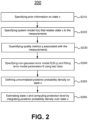
- FIG. 2 is a flow chart illustrating a method 200 for determining a protection level of a position estimate, consistent with some embodiments of the present disclosure.
- the method may be performed by a device, such as device 100 of FIG. 1 .
- method 200 includes a step S210 of specifying prior information on the state x.
- a prior probability density P ( x ) of the state x may be specified using knowledge about the state x before making the measurements.
- specifying the prior information may be performed in advance of the measurements.
- Method 200 includes a step S220 of specifying system model h ( x ) that relates the state x to the observables of the measurements.
- the observables may include a pseudorange R and a carrier phase ⁇ .
- ⁇ is a geometric range
- c is the speed of light in vacuum
- dt r and dt s are receiver and satellite clock biases from the GNSS time scale
- T is a tropospheric delay
- ⁇ f STEC is an ionospheric delay ( STEC is the slant total electron count integrating the electron density along the signal path, and ⁇ f is a frequency dependent conversion factor relating STEC to delay)
- k P,r and k P,s are receiver and satellite code instrumental delays which depend on code and frequency
- m P is an effect of multipath interference to the pseudorange
- ⁇ P is an effect of receiver noise to the pseudorange.
- k L,r and k L,s are receiver and satellite code instrumental delays, respectively
- m L is an effect of multipath interference to the carrier phase
- ⁇ is a wavelength of a transmitted GNSS signal
- n is an integer ambiguity
- w is a circular polarization wind-up
- ⁇ L is an effect of receiver noise to the carrier phase.
- the carrier phase measurements can be traditional single frequency measurements or a combination of carrier phase measurements obtained from signals at different frequencies, such as a wide-lane combination.
- a correction to the pseudorange R and a correction to the carrier phase ⁇ may be calculated using data obtained from one or several physical or virtual base stations or a correction service or an augmentation system. Specifically considering corrections coming from a base station, the base station may be a reference device whose accurate position is known. This correction may remove satellite bias terms and reduce the effect of ionospheric and tropospheric delays and mitigate errors in clocks and orbits.
- ⁇ T is a difference in tropospheric delay
- ⁇ f ⁇ STEC a difference in ionospheric delay
- ⁇ k P,r is a difference in receiver code instrumental delays
- m P , rover is an effect of multipath on the pseudorange measured at the rover
- m P,base is an effect of multipath on the pseudorange measured at the base station.
- ⁇ corrected ⁇ + c ⁇ dt r + ⁇ T - ⁇ f ⁇ STEC + ⁇ k L,r + ⁇ ( n rover - n base ) + ⁇ ⁇ w + m L,rover - m L,base + ⁇ L
- ⁇ k L,r is a difference in receiver code instrumental delays
- m L,rover is an effect of multipath on the carrier phase measured at the rover
- m L,base is an effect of multipath on the carrier phase measured at the base station
- n is an integer ambiguity
- ⁇ w is a difference in circular polarization wind-up. Both the rover and the base station receiver noises have been subsumed into ⁇ L .
- the part of the circular polarization wind-up term caused by satellite rotations can be cancelled, and for a single-epoch analysis wind-up due to rover rotations can be absorbed by the instrumental bias term ⁇ k L,r and hence neglected. If only short baselines ( ⁇ 20 km) are used, the ionospheric terms ⁇ f ⁇ STEC can also be ignored.
- the tropospheric delay is modelled using an obliquity factor M ( E ) depending only on satellite elevation E .
- ⁇ T zenith is a difference in zenith tropospheric delays.
- the observables (the pseudorange R and the carrier phase ⁇ ) are expressed as a function of the state x .
- the corrections to the observables may be optional.
- specifying the system model may be performed in advance of the measurements.
- the instrumental biases ⁇ k P,r and ⁇ k L,r include one bias per GNSS signal type, though the pseudorange bias on one GNSS is taken to be zero by definition and hence is omitted in the state vector.
- the GNSS includes GPS, Galileo (a GNSS created by the European Union), and GLONASS (a GNSS created by Russia), and therefore, a typical epoch has ten states in x (three in p , one for ⁇ dt r , two for the Galileo and GLONASS pseudorange biases ⁇ k P,r , three for the GNSS specific phase biases ⁇ k L,r and one for ⁇ T zenith ) .
- Method 200 includes a step S230 of quantifying quality metrics q associated with the measurements.
- some quality metrics such as a carrier-to-noise density ratio, an effect of multipath interference, and a satellite elevation
- quantifying the quality metrics may be performed during operation, for example, during the measurements. In checking the consistency between different satellites, the quantities which are not used by the main bound calculation, for example, changes in pseudorange and carrier phase in an immediate vicinity of the epoch of interest, may be the focus of the checking.
- some measurements that affect accuracy and consistency of the method are excluded or de-weighted. For example, some signals that are severely affected by multipath interference are identified and excluded. Some non-line-of-sight signals that are likely to create large errors are also excluded.
- the measurements that adversely affect accuracy and consistency of the method are excluded based on a random sample consensus (RANSAC) technique.
- RANSAC random sample consensus
- a set of delta-phase measurements over a one second interval, including signals in both frequency bands L1 and L2 may be the input of the RANSAC technique. Only signals which are phase-locked for at least one second can participate in this method, so all other signals are immediately excluded.
- changes in the instrumental bias ⁇ k L,r , the tropospheric delay ⁇ T zenith M ( E ), and the base station multipath m L,base are extremely small, and thus, can be ignored.
- ⁇ corrected ⁇ ⁇ + c ⁇ dt r + ⁇ ⁇ n rover ⁇ ⁇ n base + ⁇ m L , rover + ⁇ L
- ⁇ ⁇ is a change in the range over the one second interval
- ⁇ dt r is a change in the residual clock bias
- ⁇ n rover and ⁇ n base are changes in the ambiguity (i.e., cycle slips)
- ⁇ m L,rover is a change in the multipath interference contribution.
- NLOS non-line-of-sight
- ⁇ m L,rover may be large.
- Some signals may be severely affected by cycle slips, and hence ⁇ ( ⁇ n rover - ⁇ n base ) may be large.
- Signals with a multipath interference term ⁇ m L,rover greater than a threshold multipath interference or signals with a cycle slip term ⁇ ( ⁇ n rover - ⁇ n base ) greater than a threshold cycle slip may be identified as outliers, and are excluded.
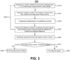
- FIG. 3 is a flow chart illustrating a method 300 for identifying outliers of GNSS measurements, consistent with some embodiments of the present disclosure.
- method 300 includes a step S310 of selecting four random satellites and randomly selecting either a L1 band or a L2 band delta-phase measurement for each satellite.
- Method 300 includes a step S320 of solving for a change in position and a change in residual clock bias using the four delta phase measurements. This is solvable because the system is a linear system with four measurements and four unknowns.
- Method 300 includes a step S330 of predicting the delta-phase for all satellites and bands using the solution in step S320. Based on the solution obtained in step S320, the delta phase for all satellites and bands can be predicted. Method 300 includes a step S340 of determining a difference between a predicted signal and an actual signal and counting the number of signals where the difference is smaller than a threshold difference. Signals where the difference between the predicted and the actual values is smaller than the threshold difference are considered as the inliers of the measurements.
- Method 300 includes a step S350 of repeating the steps 310-340 for a certain number of iterations. The number of iterations may be determined based on a confidence level that ensures an efficient convergence to the solution. Method 300 includes a step S360 of identifying a measurement that had a highest number of inliers. Step S360 is performed after all the iterations in step S350 are completed.
- Method 300 includes a step S370 of determining whether the highest inlier number is greater than a threshold inlier number (e.g., a predetermined minimum number of the inliers). If the result of the determining is "Yes”, method 300 performs a step S380 of forming a final output of the inliers of the measurements. On the other hand, if the result of the determining is "No", method 300 performs a step S390 of excluding all the signals as the outliers of the measurements.
- the number of iterations in step S350 may be 100
- the threshold difference in step S340 is 0.02 m
- the threshold number of the inliers in step S370 is 15.
- a window-based technique may be used to obtain derived quality metrics.
- the window-based quality metrics may be specified by finding consistency in both delta phase and delta pseudorange over a small window of time, for example, up to four seconds long, as described in detail below with reference to FIG. 4 .
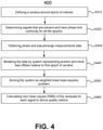
- FIG. 4 is a flow chart illustrating a method 400 for quantifying quality metrics associated with GNSS measurements, consistent with some embodiments of the present disclosure.
- method 400 includes a step S410 of defining a window around an epoch of interest.
- a width of the window is configurable.
- the window width may be a half-width of two seconds.
- the use of epochs which are after the epoch of interest implies that the algorithm has latency that equals to the window half-width when implemented in a real-time system.
- Method 400 includes a step S420 of determining signals that are present at all specified epochs (e.g., the five epochs) and have phase lock continuity for all epochs.
- signals need to be present and have phase lock continuity for all the epochs. Signals that do not meet these conditions may be excluded.
- Method 400 includes a step S430 of obtaining phase and pseudorange measurements data.
- the total number of phase measurements is given by n samples ⁇ ( n L1 + n L2 ) .
- a Doppler measurement is performed in the window around the epoch of interest, and the obtaining in step S430 is obtaining Doppler measurement data.
- Method 400 includes a step S440 of modeling the measurement data by a system that represents position and clock bias offsets relative to a first epoch of the window, along with fixed bias terms for phase and pseudorange in each band.
- Method 400 includes a step S450 of solving the system, for instance, using a weighted linear least-squares problem.
- the m data points are placed in a column vector y
- a column vector x is defined to hold the n free parameters
- a column vector of weights w is defined, with one weight for each measurement, with pseudoranges given a weight 1/ ⁇ PR and phases given a weight 1/ ⁇ phase .
- Method 400 ends with a step S460 of calculating a root mean square (RMS) of the residuals for each signal to derive the quality metrics. This amounts to determining deviation from the consensus.
- RMS root mean square
- residuals may be calculated.
- the RMS of the residuals may be calculated, and this forms the derived quality metrics.
- Phase and pseudorange metrics may be calculated separately. In an embodiment, these metrics may be used to exclude signals.
- the parameters for method 400 may be set as follows: the maximum allowed pseudorange RMS is 3 m; the maximum allowed phase RMS is 0.05 cycles; and at least 15 signals must pass both these checks, or else the entire epoch will be excluded.
- method 200 includes a step S240 of specifying a non-Gaussian error probability density model f ( r
- specifying the non-Gaussian error probability density model and fitting the model parameters may be performed in advance of the measurements, for example, off-line a priori.
- r is a residual
- v is a degrees of freedom parameter
- ⁇ is a scaling parameter which defines a width of a core distribution
- ⁇ is the gamma function.
- the parameters v and ⁇ are not constants, and may depend on the quality metrics q. In an embodiment, three quality metrics may be used: satellite elevation (el), carrier-to-noise density ratio (cno), and phase lock time (t).
- satellite elevation el
- carrier-to-noise density ratio cno
- phase lock time t
- This model has six free parameters in total: two in X 0 and four in X 1 . Bundling all these unconstrained parameters into a vector ⁇ , and all quality metrics into q , the probability density of a residual r i with quality metrics q i is written as: f pr r i ⁇ q i
- the model is identified by finding maximum likelihood values for the nine parameters (six free parameters plus residual r i , vector ⁇ , and quality metrics q i ), given a set of measurements observational data.
- P model data P data model P model P data
- the maximum likelihood model is the one which maximizes P (model
- q ) is a normalization factor and can be ignored.
- the maximum likelihood model ⁇ can then be found via standard numerical optimization.
- separate models may be created for moving and stationary epochs, as the pseudorange error distribution has different characteristics in these two cases.
- carrier phase residuals are modelled as a student-t distribution.
- the error distribution may be modeled as a student-t plus uniform mixture, bounded to the range ⁇ 0.5.
- the basic parameters w , ⁇ and v are not constants but are functions of the quality metrics.
- the remaining unconstrained parameter w' is taken to be independent of the satellite elevation. There are five free parameters in total, two in X 0 , two in X 1 and one for w' .
- the model fitting process is then similar to the method used for pseudorange. A single model covers both stationary and moving epochs, as a motion of a vehicle does not significantly affect the phase error distribution.
- Equation (46) may also be evaluated using a log-likelihood.
- FIG. 5 shows a comparison of an observed residual error distribution
- the observed residual error distribution is pseudorange residual error distribution obtained using a receiver disposed in a moving vehicle, with a satellite (Galileo) elevation between 10-30 degrees.
- the Gaussian distribution fit (420) is a poor fit to the observed residual error distribution (410), because the observed residual error distribution (410) has much heavier tails than the Gaussian distribution fit.
- the student-t distribution fit (430) is an improved fit to the observed residual error distribution (410), indicating that the student-t distribution is a better choice for modelling residual error distribution than the Gaussian distribution.
- method 200 includes a step S250 of defining an unnormalized posterior probability density on the state x.
- defining the unnormalized posterior probability density may be performed during operation.
- an unnormalized posterior probability density is defined by using Equation (8) above.
- h i ( x ) is the system model which predicts the observable z i given the state x of the system.
- P ( z ) Taking P ( z ) to be an unknown normalization constant, the final posterior probability density is given by: P x ⁇ z q ⁇ P x ⁇ i f z i ⁇ h i x ⁇ q i where P ( x ) is the prior state probability.
- P ( x ) is taken to be uniform in all states except for ⁇ T zenith , which is taken to have a Gaussian distribution centered on zero and with standard deviation 5 cm.
- Method 200 includes a step S260 of estimating state x and computing the protection level by integrating the posterior probability density over the state x .
- the state x may be estimated, for example, using the posterior probability density P ( x
- the integration may be done numerically, for example, using Markov chain Monte Carlo (MCMC) or importance sampling method.
- MCMC Markov chain Monte Carlo
- estimating the state x and computing the protection level may be performed during operation.
- the integration of the posterior probability density over the state x is performed based on MCMC, but multiple chains with modified density functions are used to give accurate estimates of tail density on a multimodal distribution.
- ⁇ min is set to a large value (e.g., 0.5 m)
- the modes merge and the distribution becomes unimodal.
- a set of ten MCMC chains are executed in parallel, each having a different value for ⁇ min .
- These chains can be considered as forming a stack of chains, with a heavily broadened unimodal chain at the top and the unbroadened chain (with ⁇ min set to 0) at the bottom.
- Adjacent chains may interact via replica exchange, i.e., the states of two adjacent chains are occasionally swapped using the usual Metropolis criterion. At the end of the sampling, only the states of the bottom (unbroadened) chain are used. This bottom chain may accurately sample the multimodal posterior probability density.
- FIG. 6 is a schematic diagram illustrating a method of multimodal sampling using parallel interacting chains, consistent with some embodiments of the present disclosure.
- Ten MCMC chains are executed in parallel (for clarity, only three chains are shown in FIG. 6 ), each having a different value for ⁇ min .
- the epoch has a bimodal posterior, with modes at -1.5 m and 0 m.
- the distribution is unimodal. In this way, using multiple chains with modified density function, the tail density on the multimodal distribution can be accurately estimated.
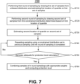
- FIG. 7 is a flow chart illustrating a method 700 for performing an umbrella sampling, consistent with some embodiments of the present disclosure.
- method 700 includes a step S710 of performing a first round of sampling by drawing a first set of samples from an unbiased distribution and estimating a first location of a quantile on the first set of samples.
- the quantile may be set as a moderate value such as 0.2. This quantile will be used to constrain the sampling pool in a second round of sampling.
- Method 700 includes a step S720 of performing a second round of sampling by drawing a second set of samples from a first constrained distribution that is determined based on the first location of the quantile.
- the first constrained distribution may be set as the tail portions of the unbiased distribution.
- Method 700 includes a step S730 of estimating a second location of the quantile on the second set of samples. The second location of the quantile is used to set a second constrained distribution for a third round of sampling.
- Method 700 includes a step S740 of repeating the sampling using a constrained distribution set in a previous sampling until an nth round of sampling is completed. For example, six rounds of sampling may be used.
- the constrained distribution set in ( n - 1 )th sampling forces sampling of only the q n portion of the tail. For example, for a quantile value of 0.2, only 0.2 portion of the tail is sampled in the first round, only 0.04 portion of the tail is sampled in the second round, and only 0.008 portion of the tail is sampled in the third round, and so on.
- Method 700 includes a step S750 of determining whether the sampling is adequate for a required protection level calculation. If the result of the determination in step S740 is "No", then the method repeats from step S740 and draws another round of samples. On the other hand, if the result of the determination in step S740 is "Yes”, in a step S760, all the samples are combined with appropriate weights, and the final protection level is determined.
- a system including a receiver (e.g., device 100 in FIG. 1 ) and a satellite was tested using a small set of trial data.
- the receiver was disposed in a vehicle, and the set of trial data was composed of data obtained by about 25 hours of driving the vehicle on highways.
- Measurement residuals were obtained using a real time kinematic (RTK) method, using a local (e.g., within 20 km) reference station and fixing the L1 and the L2 integer ambiguities.
- the same dataset was used for both fitting the error model parameters ⁇ , and for testing the protection level calculation.
- the data include measurements from both GPS, Galileo and GLONASS. Phase observations were wide-lane, and not available on GPS satellites which do not transmit a civilian L2 signal.
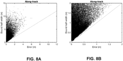
- FIG. 8A and 8B show Stanford plots showing bound half-width and true error obtained from experimental data in an along-track direction
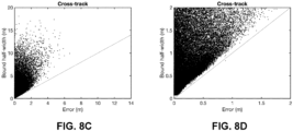
- FIG. 8C and 8D show Stanford plots showing bound half-width and true error obtained from experimental data in a cross-track dimension
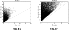
- FIG. 8E and FIG. 8F show Stanford plots showing bound half-width and true error obtained from experimental data in a vertical dimension, consistent with some embodiments of the present disclosure.
- FIG. 8A and FIG. 8B show the same data, but with different axis limits.
- FIG. 8C and FIG. 8D show the same data, but with different axis limits
- FIG. 8E and FIG. 8F show the same data, but with different axis limits.
- FIG. 8A and FIG. 8B show the same data, but with different axis limits
- FIG. 8C and FIG. 8D show the same data, but with different axis limits
- FIG. 8E and FIG. 8F show the same data, but with different axis limits.
- the single epoch position bound algorithm described above forms a core component of the integrity approach.
- the algorithm can also be used to determine the full (multi-model) posterior distribution that can be used for other applications and not only for bounds or position estimation.
- a bound propagation for example, the single epoch bound is evaluated at a low rate (e.g., once per ten seconds), and in parallel, delta phase observations and sensor data are used to propagate the most recent single epoch bound and position forward to a current time.
- the bounds at a present time are the sum of the bounds at some previous epoch, plus the bounds on the change in position since that time.
- the risk of misleading information is shared between the absolute bound calculation, and the propagation calculation. Propagation is therefore done with a similar level of integrity to the main bound calculation. By this way, the system may maintain both high availability, low latency, and reduced computational load.
- a prototype propagation scheme is used.
- the prototype propagation scheme is based on two distinct approaches: (1) modelling the error distribution on delta phase using a non-Gaussian distribution (e.g., a student-t distribution), and evaluating the bounds on delta position numerically using MCMC; and (2) modelling the error distribution using a Gaussian over-bound method, as is used by a receiver autonomous integrity monitoring (RAIM) algorithm in the aviation domain.
- a non-Gaussian distribution e.g., a student-t distribution
- MCMC e.g., a Gaussian over-bound method
- sensor-based propagation may be used together with GNSS signals or when GNSS signals are not available. For example, measurements made by a motion sensor, such as accelerometers, gyroscopes, wheel speed sensors, or any other sensors disposed in a vehicle may be used for the measurements. In the sensor-based propagation, an extended Kalman filter may be used to track the change in position. Before the outage, GNSS signals may be used to estimate the state of the system (e.g., the orientation and the sensor biases).
- a motion sensor such as accelerometers, gyroscopes, wheel speed sensors, or any other sensors disposed in a vehicle may be used for the measurements.
- an extended Kalman filter may be used to track the change in position.
- GNSS signals may be used to estimate the state of the system (e.g., the orientation and the sensor biases).
- one or more model parameters may be added.
- the model parameters may be estimated at the same time as the position.
- a state space representation (SSR) correction service may be used instead of a local reference station.
- the error associated with the SSR correction service may be treated as a coordinate shift in the solution, and therefore may restore the bound validity by expanding the limits to allow for the possible magnitude of this shift.
- the SSR errors may be modelled explicitly.
- the computer-readable storage medium of the present disclosure may be a tangible device that can store instructions for use by an instruction execution device.
- the computer-readable storage medium may be, for example, but is not limited to, an electronic storage device, a magnetic storage device, an optical storage device, an electromagnetic storage device, a semiconductor storage device, or any suitable combination of the foregoing.
- a non-exhaustive list of more specific examples of the computer-readable storage medium includes the following: a portable computer diskette, a hard disk, a random access memory (RAM), a read-only memory (ROM), an erasable programmable read-only memory (EPROM), a static random access memory (SRAM), a portable compact disc read-only memory (CD-ROM), a digital versatile disk (DVD), a memory stick, a floppy disk, a mechanically encoded device such as punch-cards or raised structures in a groove having instructions recorded thereon, and any suitable combination of the foregoing.
- RAM random access memory
- ROM read-only memory
- EPROM erasable programmable read-only memory
- SRAM static random access memory
- CD-ROM compact disc read-only memory
- DVD digital versatile disk
- memory stick a floppy disk
- a mechanically encoded device such as punch-cards or raised structures in a groove having instructions recorded thereon
- the computer-readable program instructions of the present disclosure may be assembler instructions, instruction-set-architecture (ISA) instructions, machine instructions, machine-dependent instructions, microcode, firmware instructions, state-setting data, or source code or object code written in any combination of one or more programming languages, including an object-oriented programming language, and conventional procedural programming languages.
- the computer-readable program instructions may execute entirely on a computing device as a stand-alone software package, or partly on a first computing device and partly on a second computing device remote from the first computing device. In the latter scenario, the second, remote computing device may be connected to the first computing device through any type of network, including a local area network (LAN) or a wide area network (WAN).
- LAN local area network
- WAN wide area network
- exemplary is used herein to mean serving as an example, instance, or illustration. Any aspect or design described herein as “exemplary” is not necessarily to be construed as preferred or advantageous over other aspects or designs. Rather, use of the word is intended to present concepts in a concrete fashion.
- the term "or" encompasses all possible combinations, except where infeasible.
- a database may include A or B, then, unless specifically stated otherwise or infeasible, the database may include A, or B, or A and B.
- the database may include A, or B, or C, or A and B, or A and C, or B and C, or A and B and C.
Landscapes
- Engineering & Computer Science (AREA)
- Radar, Positioning & Navigation (AREA)
- Remote Sensing (AREA)
- Computer Networks & Wireless Communication (AREA)
- Physics & Mathematics (AREA)
- General Physics & Mathematics (AREA)
- Signal Processing (AREA)
- Computer Security & Cryptography (AREA)
- Position Fixing By Use Of Radio Waves (AREA)
Applications Claiming Priority (2)
| Application Number | Priority Date | Filing Date | Title |
|---|---|---|---|
| US16/779,464 US11885890B2 (en) | 2020-01-31 | 2020-01-31 | Method and apparatus of single epoch position bound |
| EP20170246.1A EP3859397B1 (de) | 2020-01-31 | 2020-04-17 | Verfahren und vorrichtung für eine positionierung begrenzt auf eine einzelne epoche |
Related Parent Applications (2)
| Application Number | Title | Priority Date | Filing Date |
|---|---|---|---|
| EP20170246.1A Division EP3859397B1 (de) | 2020-01-31 | 2020-04-17 | Verfahren und vorrichtung für eine positionierung begrenzt auf eine einzelne epoche |
| EP20170246.1A Division-Into EP3859397B1 (de) | 2020-01-31 | 2020-04-17 | Verfahren und vorrichtung für eine positionierung begrenzt auf eine einzelne epoche |
Publications (2)
| Publication Number | Publication Date |
|---|---|
| EP4498129A2 true EP4498129A2 (de) | 2025-01-29 |
| EP4498129A3 EP4498129A3 (de) | 2025-04-23 |
Family
ID=70333810
Family Applications (2)
| Application Number | Title | Priority Date | Filing Date |
|---|---|---|---|
| EP20170246.1A Active EP3859397B1 (de) | 2020-01-31 | 2020-04-17 | Verfahren und vorrichtung für eine positionierung begrenzt auf eine einzelne epoche |
| EP24219117.9A Pending EP4498129A3 (de) | 2020-01-31 | 2020-04-17 | Verfahren und vorrichtung für positionsbegrenzung einer einzelnen zeitperiode |
Family Applications Before (1)
| Application Number | Title | Priority Date | Filing Date |
|---|---|---|---|
| EP20170246.1A Active EP3859397B1 (de) | 2020-01-31 | 2020-04-17 | Verfahren und vorrichtung für eine positionierung begrenzt auf eine einzelne epoche |
Country Status (3)
| Country | Link |
|---|---|
| US (2) | US11885890B2 (de) |
| EP (2) | EP3859397B1 (de) |
| CN (1) | CN113281793B (de) |
Families Citing this family (23)
| Publication number | Priority date | Publication date | Assignee | Title |
|---|---|---|---|---|
| EP3963352A4 (de) | 2019-05-01 | 2023-09-20 | Swift Navigation, Inc. | Systeme und verfahren zur satellitenortung mit hoher integrität |
| CN114430808B (zh) * | 2019-06-06 | 2025-04-29 | 星盟国际有限公司 | 变化电离层延迟下的单历元伪距定位 |
| US20220080991A1 (en) * | 2020-09-11 | 2022-03-17 | Beijing Wodong Tianjun Information Technology Co., Ltd. | System and method for reducing uncertainty in estimating autonomous vehicle dynamics |
| EP4036606A1 (de) | 2021-01-29 | 2022-08-03 | u-blox AG | Kalibrierung einer fahrzeugmontierten gnss-antenne |
| CN113792371B (zh) * | 2021-09-27 | 2024-01-26 | 江西科技学院 | 基于锁相值的轨道异常匹配的诊断方法 |
| US20240337755A1 (en) * | 2021-09-28 | 2024-10-10 | Qualcomm Incorporated | Precise positioning engine (ppe) base station swap handling |
| CN116249144B (zh) * | 2021-12-07 | 2025-12-12 | 广州海格通信集团股份有限公司 | 通信频率确定方法、装置、电子设备及存储介质 |
| CN114329342B (zh) * | 2021-12-20 | 2024-02-06 | 中交第二公路勘察设计研究院有限公司 | 基于极值-高斯混合分布模型的高速公路通行能力计算方法 |
| JP2025505921A (ja) * | 2022-01-07 | 2025-03-05 | クゥアルコム・インコーポレイテッド | 無線アクセス技術依存測位支援データのための完全性情報 |
| EP4235206B1 (de) * | 2022-02-25 | 2025-01-22 | Nokia Solutions and Networks Oy | Vorrichtung mit mindestens einem prozessor |
| EP4307009A1 (de) | 2022-07-11 | 2024-01-17 | u-blox AG | Gnss-messungsverarbeitung zur identifizierung von modi |
| EP4307008A1 (de) | 2022-07-11 | 2024-01-17 | u-blox AG | Gnss-messverarbeitung mit trägerphasen-restfehlermodell |
| EP4307012A1 (de) | 2022-07-11 | 2024-01-17 | u-blox AG | Gnss-messverarbeitung und restfehlermodellschätzung |
| CN115144411B (zh) * | 2022-09-05 | 2022-12-06 | 国家卫星海洋应用中心 | 基于卫星散射计的海冰检测的方法、装置、设备和介质 |
| US12019163B2 (en) | 2022-09-12 | 2024-06-25 | Swift Navigation, Inc. | System and method for GNSS correction transmission |
| US12498493B2 (en) | 2022-10-21 | 2025-12-16 | Swift Navigation, Inc. | System and method for distributed integrity monitoring |
| CN116256785A (zh) * | 2022-12-12 | 2023-06-13 | 西南交通大学 | 基于相位误差mcmc快速估计的gnss单历元定位方法 |
| WO2024129723A1 (en) * | 2022-12-15 | 2024-06-20 | Swift Navigation, Inc. | System and method for bounding a satellite positioning solution integrity |
| DE102023206473A1 (de) * | 2023-07-07 | 2025-01-09 | Robert Bosch Gesellschaft mit beschränkter Haftung | Verfahren zur Bestimmung von Protection-Levels bei der Fahrt eines Fahrzeuges mit einem GNSS-gestützten Lokalisierungssystem mit Hilfe eines copula-gestützten Bayes'schen Frameworks |
| EP4517386A3 (de) | 2023-08-08 | 2025-05-07 | u-blox AG | Integration für gnss-messungsverarbeitung |
| EP4506732A1 (de) | 2023-08-08 | 2025-02-12 | u-blox AG | Gnss-messungsverarbeitung zur identifizierung von modi |
| CN116794695B (zh) * | 2023-08-22 | 2023-10-24 | 中国科学院空天信息创新研究院 | 基于双重优化的高程辅助低轨卫星机会信号定位方法 |
| CN116819585B (zh) * | 2023-08-31 | 2023-12-29 | 长沙金维信息技术有限公司 | 基于非线性优化的gnss单点定位方法及导航方法 |
Citations (1)
| Publication number | Priority date | Publication date | Assignee | Title |
|---|---|---|---|---|
| WO2018121879A1 (en) | 2016-12-30 | 2018-07-05 | U-Blox Ag | Gnss receiver protection levels |
Family Cites Families (6)
| Publication number | Priority date | Publication date | Assignee | Title |
|---|---|---|---|---|
| US5623414A (en) * | 1995-01-24 | 1997-04-22 | Massachusetts Inst Technology | Clock-aided satellite navigation receiver system for enhanced position estimation and integrity monitoring |
| ES2427975T3 (es) * | 2005-06-02 | 2013-11-05 | Gmv Aerospace And Defence S.A. | Método y sistema para proporcionar una solución de posición de navegación de GNSS con una integridad garantizada en entornos no controlados |
| WO2014171999A2 (en) * | 2013-02-04 | 2014-10-23 | Vanderbilt University | Method and system for high-accuracy differential tracking of global positioning system (gps) receivers |
| US10244362B2 (en) * | 2013-10-08 | 2019-03-26 | Gozio Inc. | Use of RF-based fingerprinting for indoor positioning by mobile technology platforms |
| CN106569233B (zh) * | 2016-11-03 | 2019-03-19 | 中国铁路总公司 | 基于学生t分布的接收机自主完好性检测和故障排除方法 |
| CN109932735B (zh) * | 2019-03-25 | 2023-04-07 | 中国铁路设计集团有限公司 | 北斗短基线单频单历元解算的定位方法 |
-
2020
- 2020-01-31 US US16/779,464 patent/US11885890B2/en active Active
- 2020-04-17 EP EP20170246.1A patent/EP3859397B1/de active Active
- 2020-04-17 EP EP24219117.9A patent/EP4498129A3/de active Pending
-
2021
- 2021-02-01 CN CN202110138235.7A patent/CN113281793B/zh active Active
-
2023
- 2023-12-13 US US18/537,921 patent/US20240118433A1/en active Pending
Patent Citations (1)
| Publication number | Priority date | Publication date | Assignee | Title |
|---|---|---|---|---|
| WO2018121879A1 (en) | 2016-12-30 | 2018-07-05 | U-Blox Ag | Gnss receiver protection levels |
Also Published As
| Publication number | Publication date |
|---|---|
| US20210239845A1 (en) | 2021-08-05 |
| EP4498129A3 (de) | 2025-04-23 |
| US20240118433A1 (en) | 2024-04-11 |
| CN113281793B (zh) | 2026-01-13 |
| EP3859397B1 (de) | 2025-01-22 |
| US11885890B2 (en) | 2024-01-30 |
| CN113281793A (zh) | 2021-08-20 |
| EP3859397A1 (de) | 2021-08-04 |
Similar Documents
| Publication | Publication Date | Title |
|---|---|---|
| EP3859397B1 (de) | Verfahren und vorrichtung für eine positionierung begrenzt auf eine einzelne epoche | |
| US11237276B2 (en) | System and method for gaussian process enhanced GNSS corrections generation | |
| US20240142637A1 (en) | System and method for gaussian process enhanced gnss corrections generation | |
| US11860260B2 (en) | Systems and methods for high-integrity satellite positioning | |
| CN101099090B (zh) | 定位装置与方法 | |
| US9291716B2 (en) | Method and apparatus for determining physical characteristics of a receiving device in a navigation system | |
| US20190302274A1 (en) | System and Method for GNSS Ambiguity Resolution | |
| US6552681B1 (en) | Method for determining vertical and horizontal GPS position using altitude information | |
| JP6234549B2 (ja) | 測位装置 | |
| EP4103972B1 (de) | System und verfahren zur ganzzahlfreien gnss-positionierung | |
| JP2010528320A (ja) | リアルタイムキネマティック(rtk)測位における距離依存性誤差の軽減 | |
| US11474263B2 (en) | System and method for GNSS ambiguity resolution | |
| CN105738926A (zh) | 一种glonass系统接收机间相位频间偏差标定方法 | |
| CN112505735B (zh) | 对终端进行定位的方法、装置和存储介质 | |
| CN118339480A (zh) | 一种数据预处理方法、数据预处理装置和芯片 | |
| JP6546730B2 (ja) | 衛星信号受信装置 | |
| Bong et al. | GNSS performance enhancement using measurement estimation in harsh environment | |
| JP2008039691A (ja) | 搬送波位相式測位装置 | |
| Bryant et al. | Novel snapshot integrity algorithm for automotive applications: Test results based on real data | |
| KR101803652B1 (ko) | 광역 보강 시스템의 전리층 불균질 위협모델을 위한 기하학적 측정 메트릭 개발을 통한 sbas 가용성 향상 방법 및 장치 | |
| Hu et al. | Advance on Pseudolite Network Selection for Optimal Positioning | |
| Viandier et al. | Studies on dpm for the density estimation of pseudorange noises and evaluations on real data | |
| WO2025196730A1 (en) | Position estimation using a modeled loss function | |
| HK40040656A (en) | Method and apparatus for positioning terminal, and storage medium | |
| HK40040656B (en) | Method and apparatus for positioning terminal, and storage medium |
Legal Events
| Date | Code | Title | Description |
|---|---|---|---|
| PUAI | Public reference made under article 153(3) epc to a published international application that has entered the european phase |
Free format text: ORIGINAL CODE: 0009012 |
|
| STAA | Information on the status of an ep patent application or granted ep patent |
Free format text: STATUS: THE APPLICATION HAS BEEN PUBLISHED |
|
| AC | Divisional application: reference to earlier application |
Ref document number: 3859397 Country of ref document: EP Kind code of ref document: P |
|
| AK | Designated contracting states |
Kind code of ref document: A2 Designated state(s): AL AT BE BG CH CY CZ DE DK EE ES FI FR GB GR HR HU IE IS IT LI LT LU LV MC MK MT NL NO PL PT RO RS SE SI SK SM TR |
|
| PUAL | Search report despatched |
Free format text: ORIGINAL CODE: 0009013 |
|
| AK | Designated contracting states |
Kind code of ref document: A3 Designated state(s): AL AT BE BG CH CY CZ DE DK EE ES FI FR GB GR HR HU IE IS IT LI LT LU LV MC MK MT NL NO PL PT RO RS SE SI SK SM TR |
|
| RIC1 | Information provided on ipc code assigned before grant |
Ipc: G01S 19/20 20100101AFI20250319BHEP |
|
| STAA | Information on the status of an ep patent application or granted ep patent |
Free format text: STATUS: REQUEST FOR EXAMINATION WAS MADE |
|
| 17P | Request for examination filed |
Effective date: 20251022 |