EP4497978A2 - Aufblasbarer gegenstand und ventil dafür - Google Patents
Aufblasbarer gegenstand und ventil dafür Download PDFInfo
- Publication number
- EP4497978A2 EP4497978A2 EP24204556.5A EP24204556A EP4497978A2 EP 4497978 A2 EP4497978 A2 EP 4497978A2 EP 24204556 A EP24204556 A EP 24204556A EP 4497978 A2 EP4497978 A2 EP 4497978A2
- Authority
- EP
- European Patent Office
- Prior art keywords
- way flap
- inflatable object
- valve body
- passageway
- chamber
- Prior art date
- Legal status (The legal status is an assumption and is not a legal conclusion. Google has not performed a legal analysis and makes no representation as to the accuracy of the status listed.)
- Pending
Links
Images




Classifications
-
- A—HUMAN NECESSITIES
- A47—FURNITURE; DOMESTIC ARTICLES OR APPLIANCES; COFFEE MILLS; SPICE MILLS; SUCTION CLEANERS IN GENERAL
- A47C—CHAIRS; SOFAS; BEDS
- A47C27/00—Spring, stuffed or fluid mattresses or cushions specially adapted for chairs, beds or sofas
- A47C27/08—Fluid mattresses
- A47C27/081—Fluid mattresses of pneumatic type
-
- F—MECHANICAL ENGINEERING; LIGHTING; HEATING; WEAPONS; BLASTING
- F16—ENGINEERING ELEMENTS AND UNITS; GENERAL MEASURES FOR PRODUCING AND MAINTAINING EFFECTIVE FUNCTIONING OF MACHINES OR INSTALLATIONS; THERMAL INSULATION IN GENERAL
- F16K—VALVES; TAPS; COCKS; ACTUATING-FLOATS; DEVICES FOR VENTING OR AERATING
- F16K15/00—Check valves
- F16K15/02—Check valves with guided rigid valve members
- F16K15/03—Check valves with guided rigid valve members with a hinged closure member or with a pivoted closure member
- F16K15/031—Check valves with guided rigid valve members with a hinged closure member or with a pivoted closure member the hinge being flexible
-
- F—MECHANICAL ENGINEERING; LIGHTING; HEATING; WEAPONS; BLASTING
- F16—ENGINEERING ELEMENTS AND UNITS; GENERAL MEASURES FOR PRODUCING AND MAINTAINING EFFECTIVE FUNCTIONING OF MACHINES OR INSTALLATIONS; THERMAL INSULATION IN GENERAL
- F16K—VALVES; TAPS; COCKS; ACTUATING-FLOATS; DEVICES FOR VENTING OR AERATING
- F16K15/00—Check valves
- F16K15/14—Check valves with flexible valve members
- F16K15/148—Check valves with flexible valve members the closure elements being fixed in their centre
-
- F—MECHANICAL ENGINEERING; LIGHTING; HEATING; WEAPONS; BLASTING
- F16—ENGINEERING ELEMENTS AND UNITS; GENERAL MEASURES FOR PRODUCING AND MAINTAINING EFFECTIVE FUNCTIONING OF MACHINES OR INSTALLATIONS; THERMAL INSULATION IN GENERAL
- F16K—VALVES; TAPS; COCKS; ACTUATING-FLOATS; DEVICES FOR VENTING OR AERATING
- F16K15/00—Check valves
- F16K15/20—Check valves specially designed for inflatable bodies, e.g. tyres
- F16K15/202—Check valves specially designed for inflatable bodies, e.g. tyres and with flexible valve member
-
- F—MECHANICAL ENGINEERING; LIGHTING; HEATING; WEAPONS; BLASTING
- F16—ENGINEERING ELEMENTS AND UNITS; GENERAL MEASURES FOR PRODUCING AND MAINTAINING EFFECTIVE FUNCTIONING OF MACHINES OR INSTALLATIONS; THERMAL INSULATION IN GENERAL
- F16K—VALVES; TAPS; COCKS; ACTUATING-FLOATS; DEVICES FOR VENTING OR AERATING
- F16K15/00—Check valves
- F16K15/20—Check valves specially designed for inflatable bodies, e.g. tyres
- F16K15/205—Check valves specially designed for inflatable bodies, e.g. tyres and with closure plug
-
- F—MECHANICAL ENGINEERING; LIGHTING; HEATING; WEAPONS; BLASTING
- F16—ENGINEERING ELEMENTS AND UNITS; GENERAL MEASURES FOR PRODUCING AND MAINTAINING EFFECTIVE FUNCTIONING OF MACHINES OR INSTALLATIONS; THERMAL INSULATION IN GENERAL
- F16K—VALVES; TAPS; COCKS; ACTUATING-FLOATS; DEVICES FOR VENTING OR AERATING
- F16K27/00—Construction of housing; Use of materials therefor
- F16K27/02—Construction of housing; Use of materials therefor of lift valves
- F16K27/0209—Check valves or pivoted valves
-
- F—MECHANICAL ENGINEERING; LIGHTING; HEATING; WEAPONS; BLASTING
- F16—ENGINEERING ELEMENTS AND UNITS; GENERAL MEASURES FOR PRODUCING AND MAINTAINING EFFECTIVE FUNCTIONING OF MACHINES OR INSTALLATIONS; THERMAL INSULATION IN GENERAL
- F16K—VALVES; TAPS; COCKS; ACTUATING-FLOATS; DEVICES FOR VENTING OR AERATING
- F16K7/00—Diaphragm valves or cut-off apparatus, e.g. with a member deformed, but not moved bodily, to close the passage ; Pinch valves
- F16K7/12—Diaphragm valves or cut-off apparatus, e.g. with a member deformed, but not moved bodily, to close the passage ; Pinch valves with flat, dished, or bowl-shaped diaphragm
- F16K7/126—Diaphragm valves or cut-off apparatus, e.g. with a member deformed, but not moved bodily, to close the passage ; Pinch valves with flat, dished, or bowl-shaped diaphragm the seat being formed on a rib perpendicular to the fluid line
-
- F—MECHANICAL ENGINEERING; LIGHTING; HEATING; WEAPONS; BLASTING
- F17—STORING OR DISTRIBUTING GASES OR LIQUIDS
- F17B—GAS-HOLDERS OF VARIABLE CAPACITY
- F17B1/00—Gas-holders of variable capacity
- F17B1/02—Details
-
- F—MECHANICAL ENGINEERING; LIGHTING; HEATING; WEAPONS; BLASTING
- F17—STORING OR DISTRIBUTING GASES OR LIQUIDS
- F17B—GAS-HOLDERS OF VARIABLE CAPACITY
- F17B1/00—Gas-holders of variable capacity
- F17B1/02—Details
- F17B1/12—Gas admission or discharge arrangements
-
- F—MECHANICAL ENGINEERING; LIGHTING; HEATING; WEAPONS; BLASTING
- F17—STORING OR DISTRIBUTING GASES OR LIQUIDS
- F17B—GAS-HOLDERS OF VARIABLE CAPACITY
- F17B1/00—Gas-holders of variable capacity
- F17B1/24—Gas-holders of variable capacity of dry type
- F17B1/26—Gas-holders of variable capacity of dry type with flexible walls, e.g. bellows
Definitions
- the specification relates generally to inflatable objects and more particularly to valves for inflatable objects.
- inflatable objects with a valve permitting a user to manually inflate and deflate the object.
- the valve employs some kind of one-way flow mechanism to permit air to be pushed into the object, while inhibiting air from leaving the object during between puffs by the user.
- These one-way flow mechanism sometimes require substantial effort to overcome, which can cause the user to tire during inflation of the object.
- the volume of air that the user needs to blow into the inflatable object can be significant and can also cause the user to become tired or dizzy. It would be advantageous to at least ameliorate one or more of these aforementioned problems or other problems with inflatable objects.
- an inflatable object which includes an inflatable object body enclosing a chamber to receive air in order to pressurize the inflatable object body, and a valve mounted to the inflatable object body.
- the valve includes a valve body that defines a passageway between the chamber and an ambient environment.
- the valve body has a shoulder.
- the valve body defines an outside end of the passageway, which opens to the ambient environment, and an inside end of the passageway, which opens into the chamber.
- the valve further includes a one-way flap that is movable between an open position in which the one-way flap permits fluid communication between the chamber and the ambient environment through the passageway, and a closed position in which the one-way flap seals against the shoulder to block fluid communication between the chamber and the ambient environment though the passageway.
- the one-way flap is biased to the closed position with a closing force.
- the closing force is selected to be overcomable so as to move the one-way flap to the open position by an airflow by a person blowing towards the one-way flap through the passageway, without having their mouth engaged with the valve body to form a seal therewith.
- an inflatable object which includes an inflatable object body enclosing a chamber to receive air in order to pressurize the inflatable object body, and a valve mounted to the inflatable object body.
- the valve includes a valve body that defines a passageway between the chamber and an ambient environment.
- the valve body has a shoulder.
- the valve body defines an outside end of the passageway, which opens to the ambient environment, and an inside end of the passageway, which opens into the chamber.
- the valve further includes a one-way flap that is movable between an open position in which the one-way flap permits fluid communication between the chamber and the ambient environment through the passageway, and a closed position in which the one-way flap seals against the shoulder to block fluid communication between the chamber and the ambient environment though the passageway.
- the one-way flap is biased to the closed position with a closing force.
- the closing force is selected to be overcomable so as to move the one-way flap to the open position by an airflow having a speed that is less than about 48 m/s, and which is at a pressure that is lower than 1 atmosphere.
- the valve further includes a cover that is removably mountable on the outside end to form a cover seal against fluid communication between the chamber and the ambient environment.
- an inflatable object which includes an inflatable object body enclosing a chamber to receive air in order to pressurize the inflatable object body, and a valve mounted to the inflatable object body.
- the valve includes a valve body that defines a passageway between the chamber and an ambient environment.
- the valve body has a shoulder.
- the valve further includes a one-way flap that is movable between an open position in which the one-way flap permits fluid communication between the chamber and the ambient environment through the passageway, and a closed position in which the one-way flap seals against the shoulder to block fluid communication between the chamber and the ambient environment though the passageway.
- the one-way flap is biased to the closed position with a closing force.
- the valve further includes a cover that is removably mountable on the outside end to form a cover seal against fluid communication between the chamber and the ambient environment.
- the cover includes a deflation projection that projects sufficiently far from a remainder of the cover to permit the cover to be inserted into the passageway to a deflation position in which the deflation projection drives the one-way flap to the open position to permit deflation of the inflatable object.
- the valve body includes a plurality of support ribs that extend into the passageway to support the one-way flap against collapse towards the outside end.
- the one-way flap is sufficiently flexible so as to collapse towards the outside end and away from the outside end due to pressure differential across the one-way flap, but is prevented from collapsing towards the outside end in order to maintain a seal against the shoulder, due to the plurality of support ribs.
- the deflation projections is a first of a plurality of deflation projections that are positioned to permit a pass-through of one of the support ribs therebetween, such that the plurality of deflation projections are engageable the one-way flap on either side of one of the support ribs.
- each of the plurality of support ribs has a first side facing the outside end of the passageway and a second side facing away from the outside end of the passageway, and each of the plurality of support ribs is tapered from the second side towards the first side.
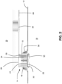
- FIG. 1 shows an inflatable object 10 in accordance with an embodiment of the present disclosure.
- the inflatable object 10 includes an inflatable object body 12, and a valve 14.
- the inflatable object body 12 encloses a chamber 16 for receiving air in order to pressurize the inflatable object body 12.
- the valve 14 is mounted to the inflatable object body 12 and includes a valve body 18, a one-way flap 20 and a cover 22.
- the valve body 18 ( Figure 2 ) defines a passageway 24 between the chamber 16 and an ambient environment 26, which is the environment outside the inflatable object 10.
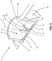
- the passageway defines a passageway axis A shown in Figure 6 .
- the valve body 18 defines an outside end 28 of the passageway 24, which opens to the ambient environment 26, and an inside end 30 of the passageway 24, which opens into the chamber 16.
- the valve body 18 further includes a shoulder 32 which is a sealing surface against which the one-way flap 20 can seal.
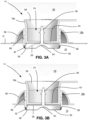
- the one-way flap 20 is movable between an open position ( Figure 3A ) in which the one-way flap 20 permits fluid communication between the chamber 16 and the ambient environment 26 through the passageway 18, and a closed position ( Figure 3B ) in which the one-way flap 20 seals against the shoulder 32 to block fluid communication between the chamber 16 and the ambient environment 26 though the passageway 18.
- the one-way flap 20 is in at least some situations biased to the closed position with a closing force F.
- the closing force F is the sum total of all the forces urging the one-way flap 20 towards the closed position. This includes one or more of the following forces: 1. an air pressure P1 inside the chamber 16 that is greater than an air pressure P2 in the ambient environment 26, 2. a resiliency in the one-way flap 20 itself urging the one-way flap 20 towards the closed position, and 3. a separate biasing member such as a spring, that urges the one-way flap 20 towards the closed position. In the example shown the one-way flap 20 is not urged to the closed position by a separate biasing member.
- the one-way flap 20 lacks sufficient resiliency to urge itself to the closed position.
- the one-way flap 20 may be sufficiently flexible to collapse away from the closed position (i.e. to collapse in a direction away from the outside end 28 of the passageway 18) in the event that the air pressure P1 in the chamber 16 is the same as the air pressure P2 in the ambient environment 26.
- the one-way flap 20 may be held in the closed position at least in part by a pressure difference across the one-way flap 20, wherein the inside air pressure P1 is greater than the outside air pressure P2. It will be noted that, initially during the inflation process for the inflatable object 10, the closing force F urging the one-way flap 20 towards the closed position may therefore be zero.
- the closing force is selected to be sufficiently low that, during at least a first portion of the inflation process, the closing force F will be non-zero, due at least to the pressure difference between P1 and P2, but will be low enough so as to be overcomable so as to move the one-way flap to the open position by an airflow having a speed that is less than about 48 m/s, and which is at a pressure that is lower than 1 atmosphere.
- This provides some significant advantages over valves for inflatable objects of the prior art.
- One advantage is that the speed is selected such that it is possible for a person to generate an airflow having the aforementioned speed of 48 m/s.
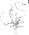
- a person can, without forming a seal with their mouth around the valve 14, blow into the valve from a distance, generating an airflow having a speed that is at least 48 m/s, as shown in Figure 4 .
- the person (which may also be referred to as a user, and which is shown at 34) is shown holding the inflatable object 10, proximate the valve 14, and blowing into the valve 14 from a distance (i.e. such that the mouth of the user 34 (shown at 36) is spaced from the valve body 18).
- the airflow generated directly from the mouth 36 of the user 34 is shown by arrows 38 and may be referred to as an initial airflow 38.
- the pressure P3 of the initial airflow 38 moving towards the one-way flap 20 is lower than the pressure P2 of the air around it in the ambient environment 26.
- air from the ambient environment 26 is drawn into the initial airflow 38, as represented by the arrows 40.
- the inlet airflow shown at 42 that enters the chamber 16 ( Figure 6 ) as a result of the blowing action by the user 34 is partly made up of air from the user's lungs (i.e. the initial airflow 38), and partly from air that was drawn into the airflow 38.
- the inflatable object 10 can be inflated using some air that did not come directly from the person's lungs. This greatly facilitates the inflation process for the inflatable object 10.
- the outside end 28 of the passageway 24 has a first cross-sectional area A1.
- a central region 34 of the passageway 24, which is inboard of the outside end 28 has a second cross-sectional area A2.
- the outside end 28 is flared and thus, the second cross-sectional area A2 is smaller than the first cross-sectional area A1. This has been found to increase the quantity of air from the ambient environment 26 that is drawn into the airflow that engages and passes past the one-way flap 20 into the chamber 16 for each blow by a person.
- the valve body 18 optionally includes a plurality of support ribs 43 that extend into the passageway to support the one-way flap 20 against collapse towards the outside end 28. More specifically, the one-way flap 20 may be sufficiently flexible so as to collapse towards the outside end 28 and away from the outside end 28 due to pressure differential across the one-way flap 20. However, the one-way flap 20 is prevented from collapsing towards the outside end 28 by the plurality of support ribs 43, in order to maintain a seal against the shoulder 32.
- Each of the plurality of support ribs 43 has a first side 44 facing the outside end 28 of the passageway 24 and a second side 46 facing away from the outside end 28 of the passageway 24. As shown somewhat in Figure 6 , and more strongly in the variant shown in Figure 7 , each of the plurality of support ribs 43 may be tapered from the second side 46 towards the first side 44. This reduces the pressure drop incurred by the inlet airflow 42 as it passes the support ribs 43.
- the one-way flap 20 may be a flexible polymeric flap that is resilient and is biased towards the closed position due to its resiliency, or that is sufficiently flexible that, at equal pressure across the one-way flap 20, the one-way flap 20 collapses away from the outside end 28.
- the one-way flap 20 may be made from any suitable material, such as, for example, silicone.
- the one-way flap 20 may be connected to the valve body 18 in any suitable way.
- the one-way flap 20 is connected to the valve body 18 at a connecting structure 48 (best seen in Figure 6 ) that is centered in the passageway 24.
- the connecting structure 48 may include a one-way flap post 50 that extends through a central annulus 52 that connects the plurality of support ribs 43 to one another.
- the one-way flap post 50 may be frictionally engaged with the inner face of the annulus, or may be connected more fixedly via an adhesive or any other suitable means.
- a collar 56 is provided and extends between the inflatable object body 12 and the valve body 18.
- the collar 56 is movable between an extended position ( Figures 3A, 3B , 5 ) in which the collar 56 holds the valve body 18 such that the outside end 28 of the passageway 24 projects outward from the inflatable object body 12, and a retracted position ( Figure 9 ) in which the collar 56 holds the valve body 18 such that the outside end 28 of the passageway 24 is positioned closer to the inflatable object body 12 than when the collar 56 is in the extended position.
- the outside end 28 may be generally flush with the inflatable object body 12.
- the collar 56 is resilient and is stable in both the extended and retracted positions, and may optionally be (but does not need to be) biased towards one of the extended and retracted positions when the collar 56 is positioned between the extended and retracted positions.
- the collar 56 may be connected to the inflatable object body 12 in any suitable way such as by thermal welding or by a suitable adhesive.
- the valve body 18 includes a valve body main portion 18a and a reinforcement member 18b.
- the valve body main portion 18a is made of a first material having a first hardness.
- the valve body 18a may be made from a polymeric material that is easily deformable manually by a person, such as a soft PVC.
- the valve body main portion 18a may be contiguous with the collar 56.
- the reinforcement member 18b is made from a second material that has a second hardness that is greater than the first hardness.
- the reinforcement member 18b may, for example, be made from a rigid polymeric material, such as a rigid PVC.
- the reinforcement member 18b is connected to the valve body main portion 18a so as to reinforce the valve body main portion 18a.
- the connection to the valve body main portion 18a may be by any suitable means.
- the reinforcement member 18b may include connection aperture 58 and the valve body 18a may be overmolded through the connection apertures 58 or may include premolded projections that engage the connection apertures 58.
- glue may be used to hold the two elements to one another securely.
- the inside end 30 of the passageway 24 has an inside end edge 60, which has a plurality of peaks 62 and valleys 64, where at least the peaks 62 extend further inwardly relative to the one-way flap 20. It has been found that the peaks 62 and the valleys 64 facilitate movement of the one-way flap 20 to the closed position. More specifically, the valleys 64 facilitate the flow of air into the chamber 16 even when the one-way flap 20 is only open by a small amount, while the peaks 62 help to protect the one-way flap 20 from mechanical damage.
- the inside end edge 60 is formed on the reinforcement member 18b, so that it can be more effective at protecting the one-way flap 20 from damage than if it were defined on the valve body main portion 18a which is softer than the reinforcement member 18b.
- the peaks 62 and valleys 64 permit the one-way flap 20 to open and close to permit air to flow into (or out of) the chamber 16, even if the inside end 30 of the passageway 24 wound up abutted against a wall of the inflatable object body 12 inside the chamber 16.
- the portion of the valve body 18 that extends into the chamber 16 axially past the one-way flap 20 (when the one-way flap 20 is in the closed position) may be referred to as an extension portion 66.
- the peaks 62 and valleys 64, and the inside end edge 60 are on the extension portion 66.
- Figure 14 shows an example of such a case, where the inside end 30 of the passageway 24 is abutted directly against a wall shown at 65 of the inflatable object body 12.
- the extension portion 66 permits the one-way flap 20 to move to the open position, and the peaks 62 and valleys 64 cooperate to define a plurality of air apertures 67 for air to pass into the chamber 16 (or out of the chamber 16) when the one-way flap 20 is in the open position (which is shown in Figure 14 ).
- valve body 18 has an extension portion 66 which extends into the chamber 16 past the one-way flap 20 and which has a plurality of projections 62 and valleys 64 which define a plurality of air apertures 67 so as to permit movement of the one-way flap 20 to the open position, so as to permit air to flow into the chamber 16 in the event that the inside end 30 of the passageway 24 is engaged with a wall 67 of the inflatable object body 18 inside the chamber.
- the cover 22 is removably mountable on the outside end 28 of the passageway 24, to form a cover seal against fluid communication between the chamber 16 and the ambient environment 26.
- the seal formed by the cover 22 becomes the only seal holding air in the chamber 16.
- the seal formed by the cover 22 cooperates with the seal formed by the one-way flap 20 to hold air in the chamber 16.
- a user 34 may pull the valve 14 out and open the cover 22 so that the valve 14 is in the position shown in Figure 2 .
- the user 34 may spread out the inflatable object body 12 so that it is ready to receive air.
- the user 34 may then blow towards the valve 14 as shown in Figure 4 , thereby filling the chamber 16 with air from the user's lungs and with air from the ambient environment 26.
- the one-way flap 20 is moved by the differential pressure thereacross to the closed position if it was collapsed. Further blowing by the user 34 further fills the chamber 16 with air as described above.
- the pressure P2 in the chamber 16 is high enough that the speed of the initial airflow 38 generated by the user 34 is not high enough to open the one-way flap 20.
- the chamber 16 has a significant amount of air in it, and may be very close to full.
- the user 34 then may form a seal with their mouth 36 around the outside end 28 of the valve body 18 and blow into the chamber 16 using pressure from their lungs instead of using the speed of the air.
- the user 34 may then close the cover 22 on the outside end 28 of the valve body 18, and may push the valve 14 inwardly so that the collar 56 moves to the retracted position.
- the user 34 may open the cover 22 and may mechanically push the one-way flap 20, if necessary, to break its seal with the shoulder 32.
- the user 34 may hold the one-way flap 20 in this open position all the while the chamber 16 is deflating.
- the cover 22 may optionally include a deflation projection 68 that projects sufficiently far from a remainder of the cover 22 to permit the cover 22 to be inserted into the passageway 28 to a deflation position shown in Figure 10 , in which the deflation projection 68 drives the one-way flap 20 to the open position to permit deflation of the inflatable object 10.
- the valve 14 may include a plurality of deflation projections 68 that are positioned to permit a pass-through of one of the support ribs 43 therebetween, so that the deflation projections 68 can engage the one-way flap 20 on either side of one of the support ribs 43.
- FIGS 11A and 11B show an alternative embodiment of the valve 14.
- the one-way flap 20 is not in Figure 11A , but is shown in Figure 11B .
- the shoulder 32 may optionally be in the form of a depression 70, such that a radially inner edge (shown at 72) of the shoulder 32 is closer to the outside end 28 of the passageway 24 than is a radially outer edge shown at 74 of the shoulder 32.
- the one-way flap 20 more easily moves between its open and closed positions and may be more prone to forming a good seal because the one-way flap 20 is always, whether in the open or closed positions, in a state of curvature in a certain direction.
- the one-way flap 20 is curved away from the outside end 28, i.e. it is curved in the direction it would be curved during the movement of air into the inflatable member 10.
- the second side 46 of the support ribs 43 cooperate with the shoulder 32 to form the depression 70. This further ensures that the one-way flap 20 remains always in a state where it is curved by some amount away from the outside end 28.
- valve 14 lacks an extension portion 66. It will be noted, however, that an extension portion could be provided with the valve 14 shown in Figures 11A and 11B .
- the connecting structure 48 is not formed by a one-way flap post that is positioned in the passageway 24, but is instead outboard from a radial edge of the passageway 24. As a result, the connecting structure 48 shown in Figure 12 interferes less with the flow of air into the chamber 16.
- the connecting structure 48 includes a flap extension 76 that extends radially outward from a remainder of the one-way flap 20 and is pinched (i.e. clamped) between an edge face 78 of the valve body main portion 18a, and a pinch surface 80 on the reinforcement member 18b.
- This arrangement in Figure 12 may also be advantageous in that the one-way flap 20 is only held in cantilever at its outermost edge, and is therefore free to flex along a length that extends across its entire diameter.
- the one-way flap 20 shown in Figure 3B for example, flexes along half of this length, since it is supported in its middle. Accordingly, the one-way flap 20 in Figure 12 may be easier to move to the open position than the one-way flap 20 shown in Figure 3B , thereby further reducing the minimum air speed needed to cause the one-way flap 20 to move to the open position.
- FIGS 13A and 13B show another embodiment of the valve 14.
- the valve 14 includes an extension portion 66 that includes an axially extending portion 82 and a radially extending portion 84, in contrast to the embodiment shown in Figures 3A and 3B , in which the extension portion 66 only extends axially and does not have a radially extending portion.
- the axially extending portion 82 can be said to include peaks 62 and valleys 64, which define air apertures 67.
- the radially extending portion 84 overlaps at least partially radially with the one-way flap 20, as can be seen particularly in Figure 13B .
- the axially extending portion 82 has the aforementioned advantages provided by the extension portion 66 shown in Figures 3A and 3B .
- a localized projection that could exist in the wall 67 of the inflatable object body 12 to enter into the extension member 66 and to obstruct the opening of the one-way flap 20 during use of the valve 14 (e.g. when inflating the inflatable object 10), or to enter into the extension portion 66 and damage the one-way flap 20.
- the wall 67 of the inflatable object body 12 is folded and piled in a certain, it could on its own form such a projection.
- the radially extending portion 84 provides additional protection to prevent localized projections inside the chamber 16 from entering into extension portion 66 and obstructing or damaging the one-way flap 20.
- the one-way flap 20 is constructed (in at least some embodiments) to be movable to the open position (i.e. to be overcomable) by a person blowing towards it without having their mouth engaged with the valve body 18 to form a seal therewith.
Landscapes
- Engineering & Computer Science (AREA)
- General Engineering & Computer Science (AREA)
- Mechanical Engineering (AREA)
- Toys (AREA)
- Check Valves (AREA)
Applications Claiming Priority (2)
| Application Number | Priority Date | Filing Date | Title |
|---|---|---|---|
| US202063034855P | 2020-06-04 | 2020-06-04 | |
| EP21177749.5A EP3919791B1 (de) | 2020-06-04 | 2021-06-04 | Aufblasbarer gegenstand und ventil dafür |
Related Parent Applications (1)
| Application Number | Title | Priority Date | Filing Date |
|---|---|---|---|
| EP21177749.5A Division EP3919791B1 (de) | 2020-06-04 | 2021-06-04 | Aufblasbarer gegenstand und ventil dafür |
Publications (2)
| Publication Number | Publication Date |
|---|---|
| EP4497978A2 true EP4497978A2 (de) | 2025-01-29 |
| EP4497978A3 EP4497978A3 (de) | 2025-04-23 |
Family
ID=76283605
Family Applications (2)
| Application Number | Title | Priority Date | Filing Date |
|---|---|---|---|
| EP21177749.5A Active EP3919791B1 (de) | 2020-06-04 | 2021-06-04 | Aufblasbarer gegenstand und ventil dafür |
| EP24204556.5A Pending EP4497978A3 (de) | 2020-06-04 | 2021-06-04 | Aufblasbarer gegenstand und ventil dafür |
Family Applications Before (1)
| Application Number | Title | Priority Date | Filing Date |
|---|---|---|---|
| EP21177749.5A Active EP3919791B1 (de) | 2020-06-04 | 2021-06-04 | Aufblasbarer gegenstand und ventil dafür |
Country Status (10)
| Country | Link |
|---|---|
| US (3) | US11543042B2 (de) |
| EP (2) | EP3919791B1 (de) |
| JP (2) | JP7702431B2 (de) |
| CN (3) | CN113898768A (de) |
| AU (3) | AU2021203682B2 (de) |
| CA (1) | CA3121057A1 (de) |
| ES (1) | ES3004134T3 (de) |
| GB (2) | GB2614132B (de) |
| MX (1) | MX2022015381A (de) |
| WO (1) | WO2021247938A1 (de) |
Families Citing this family (8)
| Publication number | Priority date | Publication date | Assignee | Title |
|---|---|---|---|---|
| GB2614132B (en) * | 2020-06-04 | 2025-11-12 | Spin Master Inc | Inflatable object and valve therefor |
| USD1069986S1 (en) * | 2021-06-09 | 2025-04-08 | Spin Master, Inc. | Valve |
| USD1039113S1 (en) * | 2021-06-09 | 2024-08-13 | Spin Master, Inc. | Valve |
| CN114427616B (zh) * | 2021-12-31 | 2022-12-23 | 浙江省军工集团股份有限公司 | 一种单向气阀及充气城堡 |
| CN115264146B (zh) * | 2022-08-15 | 2024-10-22 | 东莞市能奋五金塑胶科技有限公司 | 双气道按压快速充放阀 |
| US11767924B1 (en) * | 2022-10-13 | 2023-09-26 | Cathay Consolidated Inc. | Air valve nozzle structure for inflatable cushion |
| CN115929960A (zh) * | 2022-12-27 | 2023-04-07 | 北京大学东莞光电研究院 | 一种自动补气装置 |
| CN117617703A (zh) * | 2023-11-14 | 2024-03-01 | 宁波雪狼户外用品科技有限公司 | 一种充气床垫 |
Family Cites Families (55)
| Publication number | Priority date | Publication date | Assignee | Title |
|---|---|---|---|---|
| JPS5241124Y2 (de) * | 1972-08-28 | 1977-09-17 | ||
| US5083581A (en) | 1988-10-04 | 1992-01-28 | Jaw Horng Chang | Nozzle for inflatable objects |
| GB2225836A (en) | 1988-12-07 | 1990-06-13 | Jaw Hong Cheng | Air nozzle for inflatable articles |
| US5119842A (en) * | 1991-07-23 | 1992-06-09 | Jaw Horng Chang | Nozzle for inflatable objects |
| US5343889A (en) * | 1992-09-21 | 1994-09-06 | Jaw Horng Chang | Nozzle for inflatable objects |
| USD406238S (en) | 1997-04-28 | 1999-03-02 | Voller Ronald L | Dunnage bag valve |
| JP3587722B2 (ja) * | 1999-04-19 | 2004-11-10 | ヨツギ株式会社 | ドレン管用逆止弁 |
| US6164314A (en) | 2000-01-12 | 2000-12-26 | Intex Recreation Corp. | Oversized air valve for use with inflatable devices and method |
| US6648004B2 (en) * | 2001-02-15 | 2003-11-18 | Pleasure Time Products (Hong Kong) Limited | Air valve for inflatable article |
| GB0229870D0 (en) | 2002-12-21 | 2003-01-29 | Intersurgical Ltd | Improvements relating to closure devices |
| US6990994B2 (en) | 2003-02-21 | 2006-01-31 | Kelsyus, Llc | Valve for inflatable article |
| USD492030S1 (en) | 2003-04-23 | 2004-06-22 | Novartis Nutrition Ag | Y-port |
| US7051753B1 (en) | 2003-12-22 | 2006-05-30 | Mark Joseph Caires | Valve for a dunnage bag |
| JP2005334589A (ja) * | 2004-05-26 | 2005-12-08 | Concise:Kk | 気嚢品及び当該気嚢品用の送排気栓 |
| US7066442B2 (en) | 2004-11-23 | 2006-06-27 | Rose Machine & Tool, Llc | Valve |
| US7455086B1 (en) | 2005-01-25 | 2008-11-25 | Olaf D Elze | Valve for speed filling a dunnage bag |
| USD561329S1 (en) | 2006-10-04 | 2008-02-05 | Kimberly-Clark Worldwide, Inc. | Low profile transpyloric jejunostomy catheter |
| US20080223449A1 (en) | 2006-11-29 | 2008-09-18 | The Coleman Company, Inc. | Valve for an inflatable product |
| CN101158292A (zh) * | 2007-07-13 | 2008-04-09 | 北京航空航天大学 | 一种适用于燃气涡轮发动机的梯形交错肋冷却叶片 |
| US20090139582A1 (en) | 2007-11-30 | 2009-06-04 | Franta Thomas B | Inflation valve assembly |
| USD659235S1 (en) | 2008-06-19 | 2012-05-08 | Resmed Limited | Positive airway pressure delivery device |
| US8627852B2 (en) | 2009-01-22 | 2014-01-14 | Aptargroup, Inc. | Apertured flow control element and housing structure therefor |
| US8181664B2 (en) * | 2010-05-07 | 2012-05-22 | Dongguan Tiger Point, Metal & Plastic Products Co., Ltd. | Releasing valve for an inflatable object |
| US8281799B2 (en) * | 2010-05-19 | 2012-10-09 | Chien-Ping Lien | Valve set |
| US8584695B2 (en) * | 2010-10-15 | 2013-11-19 | Ideal Time Consultants Limited | Air valve for inflatable device |
| USD679589S1 (en) | 2011-07-12 | 2013-04-09 | Neoperl Gmbh | Closure |
| US8978693B2 (en) | 2013-01-28 | 2015-03-17 | Windcatcher Technology LLC | Inflation valve allowing for rapid inflation and deflation of an inflatable object |
| US9505334B2 (en) | 2013-08-05 | 2016-11-29 | Signode Industrial Group Llc | Valve |
| WO2015051394A1 (en) | 2013-10-08 | 2015-04-16 | Sea To Summit Pty Ltd | Improved valve for inflatable devices |
| CN103912360A (zh) * | 2014-03-21 | 2014-07-09 | 东风商用车有限公司 | 一种重型柴油发动机用电子调温器总成 |
| JP2015223208A (ja) * | 2014-05-26 | 2015-12-14 | 勝行 下田 | 気体バルブ、気体充填物及び気体の注入排出方法 |
| US20160166079A1 (en) * | 2014-12-16 | 2016-06-16 | Dongguan Tiger Point, Metal & Plastic Products Co., Tld. | Inflation device for an inflatable mattress |
| CN204647478U (zh) | 2015-02-16 | 2015-09-16 | 张刚 | 气球充气自封阀 |
| JP1552912S (de) | 2015-03-17 | 2016-06-27 | ||
| US10151396B2 (en) | 2015-11-29 | 2018-12-11 | Trong D Nguyen | Multi-purpose valve for vacuuming, de-vacuuming, gas injecting and pressure regulating |
| US9618130B1 (en) | 2015-11-29 | 2017-04-11 | Trong D Nguyen | Multi-purpose valve for extending shelf-life using vacuuming or injecting gas |
| DE202015106699U1 (de) | 2015-12-09 | 2015-12-23 | Feng Yi Outdoor Leisure Equipment Enterprise Co., Ltd. | Luftventil für eine aufblasbare Luftmatratze oder Luftmatte |
| CN107101024B (zh) | 2016-02-22 | 2020-07-07 | 浙江大自然户外用品股份有限公司 | 阀门 |
| TWI658224B (zh) | 2016-06-24 | 2019-05-01 | 美商亞根科技股份有限公司Dba克利米特 | 用於充氣/洩氣的閥 |
| USD849195S1 (en) | 2016-07-15 | 2019-05-21 | Smc Corporation | Automatic drain valve |
| USD851213S1 (en) | 2016-07-15 | 2019-06-11 | Smc Corporation | Automatic drain valve |
| CN205978669U (zh) | 2016-08-18 | 2017-02-22 | 东莞虎邦五金塑胶制品有限公司 | 一体式简易型风咀结构 |
| CN110546417B (zh) | 2017-05-04 | 2022-01-18 | 上海荣威塑胶工业有限公司 | 3合1空气阀组件 |
| DE102017110437A1 (de) | 2017-05-14 | 2018-11-15 | Vaude Gmbh & Co. Kg | Ventil für Luftmatratzen |
| US10697555B2 (en) * | 2017-08-17 | 2020-06-30 | Signode Industrial Group Llc | Valve |
| US10507474B2 (en) | 2017-12-14 | 2019-12-17 | Dongguan Tiger Point Metal & Plastic Products Co., Ltd. | Nozzle for fast inflation and deflation |
| WO2019140544A1 (zh) * | 2018-01-16 | 2019-07-25 | 和友纺织股份有限公司 | 充气用气嘴结构 |
| TWI671096B (zh) * | 2018-01-29 | 2019-09-11 | 王寧助 | 兼具分隔效果的呼氣裝置 |
| CN108678932B (zh) | 2018-05-18 | 2020-06-16 | 广东商旅宝健康科技有限公司 | 充气系统及充气方法 |
| CN210043597U (zh) | 2019-01-25 | 2020-02-11 | 贝尔格莱维亚伍德有限公司 | 充气床垫装置 |
| USD905829S1 (en) | 2019-05-28 | 2020-12-22 | Shenzhen Jiaxin Technology Co., Ltd. | Drain valve |
| US11454331B2 (en) | 2019-12-18 | 2022-09-27 | Form Create Llc | Valve cap assembly |
| GB2614132B (en) * | 2020-06-04 | 2025-11-12 | Spin Master Inc | Inflatable object and valve therefor |
| USD1017657S1 (en) | 2021-09-09 | 2024-03-12 | Thomas J. Skradski | Debris shield |
| USD970691S1 (en) | 2022-01-04 | 2022-11-22 | Shenzhen Jiaxin Technology Co., Ltd. | Rapid valve |
-
2021
- 2021-06-03 GB GB2217488.2A patent/GB2614132B/en active Active
- 2021-06-03 MX MX2022015381A patent/MX2022015381A/es unknown
- 2021-06-03 US US17/338,571 patent/US11543042B2/en active Active
- 2021-06-03 GB GB2505412.3A patent/GB2637105B/en active Active
- 2021-06-03 WO PCT/US2021/035801 patent/WO2021247938A1/en not_active Ceased
- 2021-06-03 JP JP2022574682A patent/JP7702431B2/ja active Active
- 2021-06-04 CN CN202110647349.4A patent/CN113898768A/zh active Pending
- 2021-06-04 EP EP21177749.5A patent/EP3919791B1/de active Active
- 2021-06-04 AU AU2021203682A patent/AU2021203682B2/en active Active
- 2021-06-04 EP EP24204556.5A patent/EP4497978A3/de active Pending
- 2021-06-04 ES ES21177749T patent/ES3004134T3/es active Active
- 2021-06-04 CN CN202121296230.9U patent/CN216643189U/zh active Active
- 2021-06-04 CA CA3121057A patent/CA3121057A1/en active Pending
- 2021-06-04 CN CN202221253815.7U patent/CN220416339U/zh active Active
-
2022
- 2022-11-11 AU AU2022268397A patent/AU2022268397B2/en active Active
- 2022-12-29 US US18/148,117 patent/US11808368B2/en active Active
-
2023
- 2023-07-13 AU AU2023204640A patent/AU2023204640B2/en active Active
- 2023-10-16 US US18/487,735 patent/US12270479B2/en active Active
-
2025
- 2025-06-23 JP JP2025105269A patent/JP2025128390A/ja active Pending
Also Published As
| Publication number | Publication date |
|---|---|
| MX2022015381A (es) | 2023-04-20 |
| US20240044414A1 (en) | 2024-02-08 |
| WO2021247938A1 (en) | 2021-12-09 |
| AU2023204640B2 (en) | 2024-09-26 |
| GB2614132B (en) | 2025-11-12 |
| CN113898768A (zh) | 2022-01-07 |
| EP3919791A1 (de) | 2021-12-08 |
| AU2023204640A1 (en) | 2023-08-03 |
| GB2637105B (en) | 2025-10-01 |
| JP7702431B2 (ja) | 2025-07-03 |
| ES3004134T3 (en) | 2025-03-11 |
| CN216643189U (zh) | 2022-05-31 |
| US20230145717A1 (en) | 2023-05-11 |
| JP2023529153A (ja) | 2023-07-07 |
| EP3919791B1 (de) | 2024-10-09 |
| AU2021203682B2 (en) | 2022-08-11 |
| GB2614132A (en) | 2023-06-28 |
| US12270479B2 (en) | 2025-04-08 |
| US11808368B2 (en) | 2023-11-07 |
| CA3121057A1 (en) | 2021-12-04 |
| CN220416339U (zh) | 2024-01-30 |
| US20210381611A1 (en) | 2021-12-09 |
| AU2022268397A1 (en) | 2022-12-15 |
| US11543042B2 (en) | 2023-01-03 |
| JP2025128390A (ja) | 2025-09-02 |
| AU2021203682A1 (en) | 2021-12-23 |
| EP4497978A3 (de) | 2025-04-23 |
| AU2022268397B2 (en) | 2023-04-13 |
| GB202217488D0 (en) | 2023-01-04 |
| GB2637105A (en) | 2025-07-09 |
| GB202505412D0 (en) | 2025-05-28 |
Similar Documents
| Publication | Publication Date | Title |
|---|---|---|
| AU2022268397B2 (en) | Inflatable object and valve therefor | |
| US5343889A (en) | Nozzle for inflatable objects | |
| US6164314A (en) | Oversized air valve for use with inflatable devices and method | |
| CN108784076A (zh) | 空气支承型可充气家具件及其充气方法 | |
| CN106347680B (zh) | 可收缩/可伸展吸气系统 | |
| US10640186B2 (en) | Inflation device and method of use | |
| EP0170181A2 (de) | Ventilvorrichtung zum Aufblasen von Ballons, insbesondere von an Rohren befestigten Ballons | |
| HK40064574A (en) | Inflatable object and valve therefor | |
| US7740552B2 (en) | Inflatable play ball | |
| US8617045B2 (en) | Urinary incontinence device | |
| SE429003B (sv) | Ventilanordning | |
| JP2024110520A (ja) | 胃瘻カテーテルおよび胃瘻カテーテルの製造方法 | |
| CN108146640B (zh) | 给漂浮装置充气的系统、具有撤离系统的飞机和撤离系统 | |
| US821722A (en) | Striking-bag or other fluid-receptacle. | |
| CN101321978B (zh) | 用于可充气产品的阀门 | |
| CN114375217A (zh) | 用于向乘客递送呼吸气体的系统 | |
| JPS5898509A (ja) | 多重気室構造の可撓性膜製止水堰 | |
| TWM326512U (en) | Aerated bag for preventing article from collision |
Legal Events
| Date | Code | Title | Description |
|---|---|---|---|
| PUAI | Public reference made under article 153(3) epc to a published international application that has entered the european phase |
Free format text: ORIGINAL CODE: 0009012 |
|
| STAA | Information on the status of an ep patent application or granted ep patent |
Free format text: STATUS: THE APPLICATION HAS BEEN PUBLISHED |
|
| AC | Divisional application: reference to earlier application |
Ref document number: 3919791 Country of ref document: EP Kind code of ref document: P |
|
| AK | Designated contracting states |
Kind code of ref document: A2 Designated state(s): AL AT BE BG CH CY CZ DE DK EE ES FI FR GB GR HR HU IE IS IT LI LT LU LV MC MK MT NL NO PL PT RO RS SE SI SK SM TR |
|
| REG | Reference to a national code |
Ref country code: DE Ref legal event code: R079 Free format text: PREVIOUS MAIN CLASS: F16K0015140000 Ipc: F16K0015200000 |
|
| PUAL | Search report despatched |
Free format text: ORIGINAL CODE: 0009013 |
|
| AK | Designated contracting states |
Kind code of ref document: A3 Designated state(s): AL AT BE BG CH CY CZ DE DK EE ES FI FR GB GR HR HU IE IS IT LI LT LU LV MC MK MT NL NO PL PT RO RS SE SI SK SM TR |
|
| RIC1 | Information provided on ipc code assigned before grant |
Ipc: F16K 15/14 20060101ALI20250319BHEP Ipc: A47C 27/08 20060101ALI20250319BHEP Ipc: F16K 15/20 20060101AFI20250319BHEP |
|
| STAA | Information on the status of an ep patent application or granted ep patent |
Free format text: STATUS: REQUEST FOR EXAMINATION WAS MADE |
|
| 17P | Request for examination filed |
Effective date: 20251023 |
|
| STAA | Information on the status of an ep patent application or granted ep patent |
Free format text: STATUS: EXAMINATION IS IN PROGRESS |
|
| 17Q | First examination report despatched |
Effective date: 20260407 |