EP4497649A1 - System for assembling a doorframe in a door opening of a structural part of a railway vehicle - Google Patents
System for assembling a doorframe in a door opening of a structural part of a railway vehicle Download PDFInfo
- Publication number
- EP4497649A1 EP4497649A1 EP23306281.9A EP23306281A EP4497649A1 EP 4497649 A1 EP4497649 A1 EP 4497649A1 EP 23306281 A EP23306281 A EP 23306281A EP 4497649 A1 EP4497649 A1 EP 4497649A1
- Authority
- EP
- European Patent Office
- Prior art keywords
- holding device
- plate
- door opening
- structural part
- doorframe
- Prior art date
- Legal status (The legal status is an assumption and is not a legal conclusion. Google has not performed a legal analysis and makes no representation as to the accuracy of the status listed.)
- Granted
Links
Images

Classifications
-
- B—PERFORMING OPERATIONS; TRANSPORTING
- B61—RAILWAYS
- B61D—BODY DETAILS OR KINDS OF RAILWAY VEHICLES
- B61D19/00—Door arrangements specially adapted for rail vehicles
- B61D19/02—Door arrangements specially adapted for rail vehicles for carriages
-
- B—PERFORMING OPERATIONS; TRANSPORTING
- B61—RAILWAYS
- B61D—BODY DETAILS OR KINDS OF RAILWAY VEHICLES
- B61D49/00—Other details
Definitions
- the present invention relates to a system for assembling a doorframe in a door opening of a structural part of a railway vehicle.
- a doorframe is assembled by gluing to the structural part.
- the doorframe is held by a holding device which is connected to the structural part to hold the doorframe during the drying of the glue.
- the invention is intended to allow an easy and precise positioning of the doorframe during gluing.
- the invention relates to an assembling system for assembling a doorframe in a door opening of a structural part of a railway vehicle, comprising a holding device intended to hold the doorframe, characterized in that the assembling system comprises a positioning reference plate intended to be adjustably mounted on the structural part near to the door opening, the holding device and the positioning reference plate comprising complementary solidarizing means.
- the reference plate allows making a reference position of the holding device.
- the holding device is precisely set in position, then the reference plate saves this position, so the holding device can be removed from the door opening for applying the glue on the doorframe, and the holding device is then put back on the same precise position by having the complementary solidarizing means solidarizing the holding device with the plate.
- This system is particularly adapted for railway vehicle where the doorframes are mounted from the interior of the railway vehicle.
- a system according to the invention may contain any of the following features, taken alone or in any technically possible combination.
- the invention also relates to a method for assembling a doorframe in a door opening of a structural part of a railway vehicle, using an assembling system as specified above, comprising the following steps:
- the positioning reference plate comprises elongated holes extending in horizontal direction, intended to receive screws for the adjustable mounting on the structural part, the plate being adjustably mounted on the structural part with screws not tighten, and the plate being fixed in position by tightening the screws.
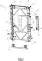
- Figure 1 shows an assembling system 10 according to an example of embodiment of the invention.
- the assembling system 10 comprises a holding device 12, a positioning reference plate 14 and a base support 16.
- the holding device 12 is intended to hold a doorframe 18 in order to assemble it in a door opening 20 of a structural part 22 (shown on Figure 3 ) of a railway vehicle.
- the holding device 12 classically comprises a main frame 24, holding parts 26 intended to hold the doorframe 18, and adjustment parts 28 intended to precisely adjust the position of the holding device 12 in the door opening 20 and to maintain it into position.
- the holding parts 26 and the adjustment parts 28 are classical and they will not be disclosed more in details.
- the base support 16 is intended to be placed at a lower part of the door opening 20.
- the holding device 12 is intended to rest on the base support 16, at a height that is imposed by the base support 16. In other words, the vertical position of the holding device 12 is simply set by placing the holding device on the base support 16.
- the reference plate 14 is intended to be adjustably mounted on the structural part 22, near the door opening 20, as shown on figure 3 .
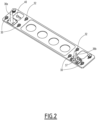
- the positioning reference plate 14 comprises elongated holes 30 extending in horizontal direction when the plate 14 is arranged on the structural part 22, each elongated hole 30 being intended to receive a respective screw 32 for the adjustable mounting on the structural part 22.
- the structural part 22 comprises holes for receiving the screws 32.
- the plate 14 can move horizontally, in the limit of the horizontal size of the elongated holes 30.
- the holding device 12 and the positioning reference plate 14 comprise complementary solidarizing means 34.
- the complementary solidarizing means 34 comprises at least two pins 36a, 36b protruding from one of the holding device 12 or the positioning reference plate 14, and at least two complementary openings 38 arranged in the other of the holding device 12 or the positioning reference plate 14.
- the pins 36a, 36b are arranged on the plate 14 and the openings 38 are arranged in the holding device 12, for example each in a respective bar fixed on the main frame 24.
- one of the pins 36b is connected to the plate 14 via a pivot 37 having an axis parallel to the direction of elongation of the elongated holes 30.
- the reference plate 14 also preferentially comprises an indicator 40 of the upper end of the plate 14, so that the plate can be arranged in a predefined direction.
- the plate 14 is adjustably mounted on the structural part 22, near the door opening 20, with the screws 32 not tightened.
- the holes in the structural part 22 receiving the screws 32 are set at a predefined height.
- the vertical position of the holding device 12 depends only of the base support 16.
- the height of the holes in the structural part 22 is predefined knowing the height of the openings 38 of the holding device 12 when the holding device 12 rests on the base support 16.
- the doorframe 18 is arranged on the holding device 12.
- the holding device 12 is brought into the door opening 20, and it is put down on the base support 16.
- the holding device 12 is solidarized with the plate 14 by means of the complementary solidarizing means 34.
- the pins 36 are inserted in the corresponding openings 38.
- the vertical position of the holding device 12 is set by the base support 16, and the horizontal position parallel to the elongated holes 30 is still free since the screws 32 are not tightened.
- the position of the holding device 12 is then adjusted in the door opening 20 in a classical way, using the adjustment parts 28 in a known manner.
- This adjustment aims to precisely adjust to position of the doorframe 18 relating to the door opening.
- the position of the plate 14 is fixed by tightening the screws 32.
- the horizontal position of the plate 14, therefore also the horizontal position of the holding device 12, are fixed.
- the holding device 12 can be removed from the door opening 20.
- the holding device 12 is set back in the door opening 20.
- the holding device 12 is positioned at the same position as the previously set position, because the vertical position is the same because of the base support 16, and the horizontal position is the same when the holding device 12 is solidarized again with the plate 14.
- the doorframe 18 is easily and quickly set into position while being provided with glue.
Landscapes
- Engineering & Computer Science (AREA)
- Mechanical Engineering (AREA)
- Transportation (AREA)
- Securing Of Glass Panes Or The Like (AREA)
Abstract
Description
- The present invention relates to a system for assembling a doorframe in a door opening of a structural part of a railway vehicle.
- Usually, a doorframe is assembled by gluing to the structural part. To this end, the doorframe is held by a holding device which is connected to the structural part to hold the doorframe during the drying of the glue.
- This is a complex operation, because the holding device have to be precisely adjusted while the doorframe is provided with glue.
- The invention is intended to allow an easy and precise positioning of the doorframe during gluing.
- To this end, the invention relates to an assembling system for assembling a doorframe in a door opening of a structural part of a railway vehicle, comprising a holding device intended to hold the doorframe, characterized in that the assembling system comprises a positioning reference plate intended to be adjustably mounted on the structural part near to the door opening, the holding device and the positioning reference plate comprising complementary solidarizing means.
- The reference plate allows making a reference position of the holding device. Thus, the holding device is precisely set in position, then the reference plate saves this position, so the holding device can be removed from the door opening for applying the glue on the doorframe, and the holding device is then put back on the same precise position by having the complementary solidarizing means solidarizing the holding device with the plate.
- This system is particularly adapted for railway vehicle where the doorframes are mounted from the interior of the railway vehicle.
- A system according to the invention may contain any of the following features, taken alone or in any technically possible combination.
- The complementary solidarizing means comprise at least two pins protruding from one of the holding device or the positioning reference plate, and at least two complementary openings arranged in the other of the holding device or the positioning reference plate.
- One of the pins is connected to the plate or holding device via a pivot.
- The pins are arranged on the plate and the holes are arranged in the holding device.
- The positioning reference plate comprises elongated holes extending in horizontal direction, intended to receive screws for the adjustable mounting on the structural part.
- The assembling system comprises a base support, the holding device being intended to rest on the base support.
- The holding device comprises a main frame, holding parts intended to hold the doorframe, and adjustment parts intended to precisely adjust the position of the holding device in the door opening and to maintain it into position.
- The invention also relates to a method for assembling a doorframe in a door opening of a structural part of a railway vehicle, using an assembling system as specified above, comprising the following steps:
- adjustably mounting the plate on the structural part, the plate being movable relating to the structural part,
- arranging the doorframe on the holding device,
- bringing the holding device into the door opening, and having the holding device solidarized with the plate by means of the solidarizing means,
- adjusting the holding device position in the door opening,
- fixing the position of the plate,
- removing the holding device from the door opening,
- applying glue on the doorframe,
- having the holding device back in the door opening, and having the holding device solidarized with the plate.
- Preferentially, the positioning reference plate comprises elongated holes extending in horizontal direction, intended to receive screws for the adjustable mounting on the structural part, the plate being adjustably mounted on the structural part with screws not tighten, and the plate being fixed in position by tightening the screws.
- Several aspects and advantages of the invention will be enlightened in the following disclosure, given only as a non-limitative example, and made in reference to the attached figures, in which:
-
Figure 1 shows a perspective view of an assembling device according to an example of embodiment of the invention; -
Figure 2 shows a perspective view of a positioning reference plate of the assembling device ofFigure 1 ; -
Figure 3 shows a perspective view of a door opening intended to receive a doorframe assembled with the assembling device. -
Figure 1 shows anassembling system 10 according to an example of embodiment of the invention. - The assembling
system 10 comprises aholding device 12, apositioning reference plate 14 and abase support 16. - The
holding device 12 is intended to hold adoorframe 18 in order to assemble it in a door opening 20 of a structural part 22 (shown onFigure 3 ) of a railway vehicle. - The
holding device 12 classically comprises amain frame 24, holdingparts 26 intended to hold thedoorframe 18, andadjustment parts 28 intended to precisely adjust the position of theholding device 12 in the door opening 20 and to maintain it into position. - The
holding parts 26 and theadjustment parts 28 are classical and they will not be disclosed more in details. - The
base support 16 is intended to be placed at a lower part of the door opening 20. Theholding device 12 is intended to rest on thebase support 16, at a height that is imposed by thebase support 16. In other words, the vertical position of theholding device 12 is simply set by placing the holding device on thebase support 16. - The
reference plate 14 is intended to be adjustably mounted on thestructural part 22, near the door opening 20, as shown onfigure 3 . - To this end, the
positioning reference plate 14 compriseselongated holes 30 extending in horizontal direction when theplate 14 is arranged on thestructural part 22, eachelongated hole 30 being intended to receive arespective screw 32 for the adjustable mounting on thestructural part 22. - The
structural part 22 comprises holes for receiving thescrews 32. When thescrews 32 are not tightened, theplate 14 can move horizontally, in the limit of the horizontal size of theelongated holes 30. - The
holding device 12 and thepositioning reference plate 14 comprise complementary solidarizing means 34. - The complementary solidarizing means 34 comprises at least two
pins holding device 12 or thepositioning reference plate 14, and at least twocomplementary openings 38 arranged in the other of theholding device 12 or thepositioning reference plate 14. In the example shown, thepins plate 14 and theopenings 38 are arranged in theholding device 12, for example each in a respective bar fixed on themain frame 24. - When each
pin corresponding opening 38, theholding device 12 and theplate 14 are bind in a horizontal direction perpendicular to a pin direction, and parallel to theelongated holes 30. - Preferentially, one of the
pins 36b is connected to theplate 14 via apivot 37 having an axis parallel to the direction of elongation of theelongated holes 30. - The
reference plate 14 also preferentially comprises anindicator 40 of the upper end of theplate 14, so that the plate can be arranged in a predefined direction. - A method for assembling the
doorframe 18 in the door opening 20 will now be disclosed. - In a first step, the
plate 14 is adjustably mounted on thestructural part 22, near the door opening 20, with thescrews 32 not tightened. The holes in thestructural part 22 receiving thescrews 32 are set at a predefined height. - As indicated before, the vertical position of the
holding device 12 depends only of thebase support 16. Thus, the height of the holes in thestructural part 22 is predefined knowing the height of theopenings 38 of theholding device 12 when theholding device 12 rests on thebase support 16. - It is reminded that the
plate 14 stays horizontally movable along theelongated holes 30 when the screws are not tightened. - In another step, before or after the step above, the
doorframe 18 is arranged on theholding device 12. - Then, the
holding device 12 is brought into the door opening 20, and it is put down on thebase support 16. - The
holding device 12 is solidarized with theplate 14 by means of the complementary solidarizing means 34. In other words, thepins 36 are inserted in thecorresponding openings 38. - At this stage, the vertical position of the
holding device 12 is set by thebase support 16, and the horizontal position parallel to theelongated holes 30 is still free since thescrews 32 are not tightened. - The position of the
holding device 12 is then adjusted in the door opening 20 in a classical way, using theadjustment parts 28 in a known manner. This adjustment aims to precisely adjust to position of thedoorframe 18 relating to the door opening. - When the
doorframe 18 is in a good position, the position of theplate 14 is fixed by tightening thescrews 32. When thescrews 32 are tightened, the horizontal position of theplate 14, therefore also the horizontal position of theholding device 12, are fixed. - Then the
holding device 12 can be removed from the door opening 20. - In a next step, a glue in applied on the
doorframe 18. - In a next step, the holding
device 12 is set back in thedoor opening 20. The holdingdevice 12 is positioned at the same position as the previously set position, because the vertical position is the same because of thebase support 16, and the horizontal position is the same when the holdingdevice 12 is solidarized again with theplate 14. - Thus, there is no need to search for the good position at this stage, because this good position was previously found.
- Because of the system of the invention, the
doorframe 18 is easily and quickly set into position while being provided with glue.
Claims (9)
- A assembling system (10) for assembling a doorframe (18) in a door opening (20) of a structural part (22) of a railway vehicle, comprising a holding device (12) intended to hold the doorframe (18), characterized in that the assembling system (10) comprises a positioning reference plate (14) intended to be adjustably mounted on the structural part (22) near to the door opening (20), the holding device (12) and the positioning reference plate (14) comprising complementary solidarizing means (34).
- The assembling system (10) of claim 1, wherein the complementary solidarizing means (34) comprise at least two pins (36a, 36b) protruding from one of the holding device (12) or the positioning reference plate (14), and at least two complementary openings (38) arranged in the other of the holding device (12) or the positioning reference plate (14).
- The assembling system (10) of claim 2, wherein one of the pins (36b) is connected to the plate (14) or holding device (12) via a pivot (37).
- The assembling system (10) of claim 2 or 3, wherein the pins (36a, 36b) are arranged on the plate (14) and the openings (38) are arranged in the holding device (12).
- The assembling system of any of preceding claims, wherein the positioning reference plate (14) comprises elongated holes (30) extending in horizontal direction, intended to receive screws (32) for the adjustable mounting on the structural part (22).
- The assembling system (10) of any of preceding claims, comprising a base support (16), the holding device (12) being intended to rest on the base support (16).
- The assembling system (10) of any of preceding claims, wherein the holding device (12) comprises a main frame (24), holding parts (26) intended to hold the doorframe (18), and adjustment parts (28) intended to precisely adjust the position of the holding device (12) in the door opening (20) and to maintain it into position.
- A method for assembling a doorframe (18) in a door opening (20) of a structural part (22) of a railway vehicle, using an assembling system (10) according to any of the preceding claims, comprising the following steps:- adjustably mounting the plate (14) on the structural part (22), the plate (14) being movable relating to the structural part (22),- arranging the doorframe (18) on the holding device (12),- bringing the holding device (12) into the door opening (20), and having the holding device (12) solidarized with the plate (14) by means of the solidarizing means (34),- adjusting the holding device (12) position in the door opening (20),- fixing the position of the plate (14),- removing the holding device (12) from the door opening (20),- applying glue on the doorframe (18),- having the holding device (12) back in the door opening (20), and having the holding device (12) solidarized with the plate (14).
- The method of claim 8, wherein the positioning reference plate (14) comprises elongated holes (30) extending in horizontal direction, intended to receive screws (32) for the adjustable mounting on the structural part (22), the plate (14) being adjustably mounted on the structural part (22) with screws (32) not tighten, and the plate (14) being fixed in position by tightening the screws (32).
Priority Applications (1)
| Application Number | Priority Date | Filing Date | Title |
|---|---|---|---|
| EP23306281.9A EP4497649B1 (en) | 2023-07-25 | 2023-07-25 | System for assembling a doorframe in a door opening of a structural part of a railway vehicle |
Applications Claiming Priority (1)
| Application Number | Priority Date | Filing Date | Title |
|---|---|---|---|
| EP23306281.9A EP4497649B1 (en) | 2023-07-25 | 2023-07-25 | System for assembling a doorframe in a door opening of a structural part of a railway vehicle |
Publications (2)
| Publication Number | Publication Date |
|---|---|
| EP4497649A1 true EP4497649A1 (en) | 2025-01-29 |
| EP4497649B1 EP4497649B1 (en) | 2025-10-29 |
Family
ID=87556231
Family Applications (1)
| Application Number | Title | Priority Date | Filing Date |
|---|---|---|---|
| EP23306281.9A Active EP4497649B1 (en) | 2023-07-25 | 2023-07-25 | System for assembling a doorframe in a door opening of a structural part of a railway vehicle |
Country Status (1)
| Country | Link |
|---|---|
| EP (1) | EP4497649B1 (en) |
Citations (5)
| Publication number | Priority date | Publication date | Assignee | Title |
|---|---|---|---|---|
| EP0990573A2 (en) * | 1998-09-30 | 2000-04-05 | DaimlerChrysler AG | Method for installing a door frame |
| DE19860555A1 (en) * | 1998-12-22 | 2000-07-06 | Abb Daimler Benz Transp | Fitting method for rail vehicle windows uses assembly frame with positioner blocks and vacuum suction elements to place adhesive-coated window modules into body cut-outs from vehicle interior |
| CN109249951A (en) * | 2018-11-23 | 2019-01-22 | 中车长春轨道客车股份有限公司 | Positioning device is used in high-order sliding slot assembly on the built-in door weather strip of bullet train and door |
| CN109834626A (en) * | 2018-12-19 | 2019-06-04 | 中车唐山机车车辆有限公司 | It is a kind of for installing the tooling of the doorframe of stopping sliding door |
| CN108406647B (en) * | 2018-03-14 | 2023-04-28 | 天津智通信息系统集成有限公司 | Fixing tool for bonding windows of motor vehicles and production line thereof |
-
2023
- 2023-07-25 EP EP23306281.9A patent/EP4497649B1/en active Active
Patent Citations (5)
| Publication number | Priority date | Publication date | Assignee | Title |
|---|---|---|---|---|
| EP0990573A2 (en) * | 1998-09-30 | 2000-04-05 | DaimlerChrysler AG | Method for installing a door frame |
| DE19860555A1 (en) * | 1998-12-22 | 2000-07-06 | Abb Daimler Benz Transp | Fitting method for rail vehicle windows uses assembly frame with positioner blocks and vacuum suction elements to place adhesive-coated window modules into body cut-outs from vehicle interior |
| CN108406647B (en) * | 2018-03-14 | 2023-04-28 | 天津智通信息系统集成有限公司 | Fixing tool for bonding windows of motor vehicles and production line thereof |
| CN109249951A (en) * | 2018-11-23 | 2019-01-22 | 中车长春轨道客车股份有限公司 | Positioning device is used in high-order sliding slot assembly on the built-in door weather strip of bullet train and door |
| CN109834626A (en) * | 2018-12-19 | 2019-06-04 | 中车唐山机车车辆有限公司 | It is a kind of for installing the tooling of the doorframe of stopping sliding door |
Also Published As
| Publication number | Publication date |
|---|---|
| EP4497649B1 (en) | 2025-10-29 |
Similar Documents
| Publication | Publication Date | Title |
|---|---|---|
| KR20090113651A (en) | Vehicle Door Hinge Mounting Device | |
| CN214641613U (en) | Automatic mounting equipment for vehicle door hinge | |
| WO2008125752A3 (en) | Device for mounting non-dimensioning equipment on the structural frame of a vehicle, vehicle fitted with such device and mounting method | |
| CN213998486U (en) | Vehicle door hinge positioning mechanism | |
| WO2005081734A2 (en) | Elevator rail support bracket | |
| EP4497649B1 (en) | System for assembling a doorframe in a door opening of a structural part of a railway vehicle | |
| US20140000986A1 (en) | Device and method for fastening and aligning a guide rail | |
| JP2010208526A (en) | Door fitting method and hinge fastening structure | |
| US5921522A (en) | Fixture for positioning an electrical box | |
| JP7489826B2 (en) | Door hinge installation jig | |
| US6212749B1 (en) | Mount assembly system | |
| JP2009040345A (en) | Automotive door hinge mounting jig and door hinge mounting method | |
| KR100676746B1 (en) | Hood Latch Assembly Device | |
| KR100839659B1 (en) | Clamping Device for Automotive Window Regulator | |
| KR100527472B1 (en) | Pre-mounting device for a door hinge | |
| US6209218B1 (en) | Squaring system | |
| CN213544276U (en) | Connecting piece experimental apparatus that shears that can assemble | |
| CN112179789A (en) | Assembled connecting piece shearing experiment device and using method | |
| KR200307846Y1 (en) | An interchange machine of shock absorber for motorcar | |
| KR101250459B1 (en) | Door fixing apparatus | |
| KR102171957B1 (en) | Check with a car hood right position and equipment | |
| KR20090063999A (en) | Car door frame calibration device | |
| WO2020260395A1 (en) | Adjustment device for load frame, testing device for material testing and method of adjusting load application elements of testing device | |
| CN220197586U (en) | Torsional spring adjusting tool and torsional spring adjusting device | |
| CN108423517B (en) | Alignment device for guide rail of elevator and method for aligning guide rail of elevator |
Legal Events
| Date | Code | Title | Description |
|---|---|---|---|
| PUAI | Public reference made under article 153(3) epc to a published international application that has entered the european phase |
Free format text: ORIGINAL CODE: 0009012 |
|
| STAA | Information on the status of an ep patent application or granted ep patent |
Free format text: STATUS: THE APPLICATION HAS BEEN PUBLISHED |
|
| AK | Designated contracting states |
Kind code of ref document: A1 Designated state(s): AL AT BE BG CH CY CZ DE DK EE ES FI FR GB GR HR HU IE IS IT LI LT LU LV MC ME MK MT NL NO PL PT RO RS SE SI SK SM TR |
|
| STAA | Information on the status of an ep patent application or granted ep patent |
Free format text: STATUS: REQUEST FOR EXAMINATION WAS MADE |
|
| 17P | Request for examination filed |
Effective date: 20250124 |
|
| GRAP | Despatch of communication of intention to grant a patent |
Free format text: ORIGINAL CODE: EPIDOSNIGR1 |
|
| STAA | Information on the status of an ep patent application or granted ep patent |
Free format text: STATUS: GRANT OF PATENT IS INTENDED |
|
| INTG | Intention to grant announced |
Effective date: 20250613 |
|
| RIN1 | Information on inventor provided before grant (corrected) |
Inventor name: BAILLOU, BERTRAND |
|
| GRAS | Grant fee paid |
Free format text: ORIGINAL CODE: EPIDOSNIGR3 |
|
| GRAA | (expected) grant |
Free format text: ORIGINAL CODE: 0009210 |
|
| STAA | Information on the status of an ep patent application or granted ep patent |
Free format text: STATUS: THE PATENT HAS BEEN GRANTED |
|
| AK | Designated contracting states |
Kind code of ref document: B1 Designated state(s): AL AT BE BG CH CY CZ DE DK EE ES FI FR GB GR HR HU IE IS IT LI LT LU LV MC ME MK MT NL NO PL PT RO RS SE SI SK SM TR |
|
| REG | Reference to a national code |
Ref country code: CH Ref legal event code: F10 Free format text: ST27 STATUS EVENT CODE: U-0-0-F10-F00 (AS PROVIDED BY THE NATIONAL OFFICE) Effective date: 20251029 Ref country code: GB Ref legal event code: FG4D |
|
| REG | Reference to a national code |
Ref country code: IE Ref legal event code: FG4D |
|
| REG | Reference to a national code |
Ref country code: DE Ref legal event code: R096 Ref document number: 602023008037 Country of ref document: DE |
|
| REG | Reference to a national code |
Ref country code: NL Ref legal event code: MP Effective date: 20251029 |
|
| PG25 | Lapsed in a contracting state [announced via postgrant information from national office to epo] |
Ref country code: ES Free format text: LAPSE BECAUSE OF FAILURE TO SUBMIT A TRANSLATION OF THE DESCRIPTION OR TO PAY THE FEE WITHIN THE PRESCRIBED TIME-LIMIT Effective date: 20251029 |
|
| REG | Reference to a national code |
Ref country code: LT Ref legal event code: MG9D |
|
| PG25 | Lapsed in a contracting state [announced via postgrant information from national office to epo] |
Ref country code: NO Free format text: LAPSE BECAUSE OF FAILURE TO SUBMIT A TRANSLATION OF THE DESCRIPTION OR TO PAY THE FEE WITHIN THE PRESCRIBED TIME-LIMIT Effective date: 20260129 |
|
| PG25 | Lapsed in a contracting state [announced via postgrant information from national office to epo] |
Ref country code: AT Free format text: LAPSE BECAUSE OF FAILURE TO SUBMIT A TRANSLATION OF THE DESCRIPTION OR TO PAY THE FEE WITHIN THE PRESCRIBED TIME-LIMIT Effective date: 20251029 Ref country code: FI Free format text: LAPSE BECAUSE OF FAILURE TO SUBMIT A TRANSLATION OF THE DESCRIPTION OR TO PAY THE FEE WITHIN THE PRESCRIBED TIME-LIMIT Effective date: 20251029 Ref country code: HR Free format text: LAPSE BECAUSE OF FAILURE TO SUBMIT A TRANSLATION OF THE DESCRIPTION OR TO PAY THE FEE WITHIN THE PRESCRIBED TIME-LIMIT Effective date: 20251029 |
|
| REG | Reference to a national code |
Ref country code: AT Ref legal event code: MK05 Ref document number: 1851260 Country of ref document: AT Kind code of ref document: T Effective date: 20251029 |
|
| PG25 | Lapsed in a contracting state [announced via postgrant information from national office to epo] |
Ref country code: NL Free format text: LAPSE BECAUSE OF FAILURE TO SUBMIT A TRANSLATION OF THE DESCRIPTION OR TO PAY THE FEE WITHIN THE PRESCRIBED TIME-LIMIT Effective date: 20251029 |
|
| PG25 | Lapsed in a contracting state [announced via postgrant information from national office to epo] |
Ref country code: RS Free format text: LAPSE BECAUSE OF FAILURE TO SUBMIT A TRANSLATION OF THE DESCRIPTION OR TO PAY THE FEE WITHIN THE PRESCRIBED TIME-LIMIT Effective date: 20260129 |
|
| PG25 | Lapsed in a contracting state [announced via postgrant information from national office to epo] |
Ref country code: IS Free format text: LAPSE BECAUSE OF FAILURE TO SUBMIT A TRANSLATION OF THE DESCRIPTION OR TO PAY THE FEE WITHIN THE PRESCRIBED TIME-LIMIT Effective date: 20260228 |
|
| PG25 | Lapsed in a contracting state [announced via postgrant information from national office to epo] |
Ref country code: PT Free format text: LAPSE BECAUSE OF FAILURE TO SUBMIT A TRANSLATION OF THE DESCRIPTION OR TO PAY THE FEE WITHIN THE PRESCRIBED TIME-LIMIT Effective date: 20260302 |
|
| PG25 | Lapsed in a contracting state [announced via postgrant information from national office to epo] |
Ref country code: PL Free format text: LAPSE BECAUSE OF FAILURE TO SUBMIT A TRANSLATION OF THE DESCRIPTION OR TO PAY THE FEE WITHIN THE PRESCRIBED TIME-LIMIT Effective date: 20251029 |
|
| PG25 | Lapsed in a contracting state [announced via postgrant information from national office to epo] |
Ref country code: LV Free format text: LAPSE BECAUSE OF FAILURE TO SUBMIT A TRANSLATION OF THE DESCRIPTION OR TO PAY THE FEE WITHIN THE PRESCRIBED TIME-LIMIT Effective date: 20251029 |
|
| PG25 | Lapsed in a contracting state [announced via postgrant information from national office to epo] |
Ref country code: BG Free format text: LAPSE BECAUSE OF FAILURE TO SUBMIT A TRANSLATION OF THE DESCRIPTION OR TO PAY THE FEE WITHIN THE PRESCRIBED TIME-LIMIT Effective date: 20251029 |
|
| PG25 | Lapsed in a contracting state [announced via postgrant information from national office to epo] |
Ref country code: LT Free format text: LAPSE BECAUSE OF FAILURE TO SUBMIT A TRANSLATION OF THE DESCRIPTION OR TO PAY THE FEE WITHIN THE PRESCRIBED TIME-LIMIT Effective date: 20251029 |
|
| PG25 | Lapsed in a contracting state [announced via postgrant information from national office to epo] |
Ref country code: SM Free format text: LAPSE BECAUSE OF FAILURE TO SUBMIT A TRANSLATION OF THE DESCRIPTION OR TO PAY THE FEE WITHIN THE PRESCRIBED TIME-LIMIT Effective date: 20251029 |
|
| PG25 | Lapsed in a contracting state [announced via postgrant information from national office to epo] |
Ref country code: DK Free format text: LAPSE BECAUSE OF FAILURE TO SUBMIT A TRANSLATION OF THE DESCRIPTION OR TO PAY THE FEE WITHIN THE PRESCRIBED TIME-LIMIT Effective date: 20251029 |
|
| PG25 | Lapsed in a contracting state [announced via postgrant information from national office to epo] |
Ref country code: IT Free format text: LAPSE BECAUSE OF FAILURE TO SUBMIT A TRANSLATION OF THE DESCRIPTION OR TO PAY THE FEE WITHIN THE PRESCRIBED TIME-LIMIT Effective date: 20251029 |
|
| PG25 | Lapsed in a contracting state [announced via postgrant information from national office to epo] |
Ref country code: EE Free format text: LAPSE BECAUSE OF FAILURE TO SUBMIT A TRANSLATION OF THE DESCRIPTION OR TO PAY THE FEE WITHIN THE PRESCRIBED TIME-LIMIT Effective date: 20251029 |
|
| PG25 | Lapsed in a contracting state [announced via postgrant information from national office to epo] |
Ref country code: CZ Free format text: LAPSE BECAUSE OF FAILURE TO SUBMIT A TRANSLATION OF THE DESCRIPTION OR TO PAY THE FEE WITHIN THE PRESCRIBED TIME-LIMIT Effective date: 20251029 |
|
| PG25 | Lapsed in a contracting state [announced via postgrant information from national office to epo] |
Ref country code: SK Free format text: LAPSE BECAUSE OF FAILURE TO SUBMIT A TRANSLATION OF THE DESCRIPTION OR TO PAY THE FEE WITHIN THE PRESCRIBED TIME-LIMIT Effective date: 20251029 |
|
| PG25 | Lapsed in a contracting state [announced via postgrant information from national office to epo] |
Ref country code: SE Free format text: LAPSE BECAUSE OF FAILURE TO SUBMIT A TRANSLATION OF THE DESCRIPTION OR TO PAY THE FEE WITHIN THE PRESCRIBED TIME-LIMIT Effective date: 20251029 |