EP4497619A1 - Hybrid power system - Google Patents
Hybrid power system Download PDFInfo
- Publication number
- EP4497619A1 EP4497619A1 EP24172700.7A EP24172700A EP4497619A1 EP 4497619 A1 EP4497619 A1 EP 4497619A1 EP 24172700 A EP24172700 A EP 24172700A EP 4497619 A1 EP4497619 A1 EP 4497619A1
- Authority
- EP
- European Patent Office
- Prior art keywords
- storage module
- motor
- electrical energy
- energy storage
- engine generator
- Prior art date
- Legal status (The legal status is an assumption and is not a legal conclusion. Google has not performed a legal analysis and makes no representation as to the accuracy of the status listed.)
- Withdrawn
Links
Images





Classifications
-
- B—PERFORMING OPERATIONS; TRANSPORTING
- B60—VEHICLES IN GENERAL
- B60K—ARRANGEMENT OR MOUNTING OF PROPULSION UNITS OR OF TRANSMISSIONS IN VEHICLES; ARRANGEMENT OR MOUNTING OF PLURAL DIVERSE PRIME-MOVERS IN VEHICLES; AUXILIARY DRIVES FOR VEHICLES; INSTRUMENTATION OR DASHBOARDS FOR VEHICLES; ARRANGEMENTS IN CONNECTION WITH COOLING, AIR INTAKE, GAS EXHAUST OR FUEL SUPPLY OF PROPULSION UNITS IN VEHICLES
- B60K6/00—Arrangement or mounting of plural diverse prime-movers for mutual or common propulsion, e.g. hybrid propulsion systems comprising electric motors and internal combustion engines
- B60K6/20—Arrangement or mounting of plural diverse prime-movers for mutual or common propulsion, e.g. hybrid propulsion systems comprising electric motors and internal combustion engines the prime-movers consisting of electric motors and internal combustion engines, e.g. HEVs
- B60K6/42—Arrangement or mounting of plural diverse prime-movers for mutual or common propulsion, e.g. hybrid propulsion systems comprising electric motors and internal combustion engines the prime-movers consisting of electric motors and internal combustion engines, e.g. HEVs characterised by the architecture of the hybrid electric vehicle
- B60K6/46—Series type
-
- B—PERFORMING OPERATIONS; TRANSPORTING
- B60—VEHICLES IN GENERAL
- B60W—CONJOINT CONTROL OF VEHICLE SUB-UNITS OF DIFFERENT TYPE OR DIFFERENT FUNCTION; CONTROL SYSTEMS SPECIALLY ADAPTED FOR HYBRID VEHICLES; ROAD VEHICLE DRIVE CONTROL SYSTEMS FOR PURPOSES NOT RELATED TO THE CONTROL OF A PARTICULAR SUB-UNIT
- B60W20/00—Control systems specially adapted for hybrid vehicles
- B60W20/10—Controlling the power contribution of each of the prime movers to meet required power demand
- B60W20/13—Controlling the power contribution of each of the prime movers to meet required power demand in order to stay within battery power input or output limits; in order to prevent overcharging or battery depletion
-
- B—PERFORMING OPERATIONS; TRANSPORTING
- B60—VEHICLES IN GENERAL
- B60K—ARRANGEMENT OR MOUNTING OF PROPULSION UNITS OR OF TRANSMISSIONS IN VEHICLES; ARRANGEMENT OR MOUNTING OF PLURAL DIVERSE PRIME-MOVERS IN VEHICLES; AUXILIARY DRIVES FOR VEHICLES; INSTRUMENTATION OR DASHBOARDS FOR VEHICLES; ARRANGEMENTS IN CONNECTION WITH COOLING, AIR INTAKE, GAS EXHAUST OR FUEL SUPPLY OF PROPULSION UNITS IN VEHICLES
- B60K1/00—Arrangement or mounting of electrical propulsion units
-
- B—PERFORMING OPERATIONS; TRANSPORTING
- B60—VEHICLES IN GENERAL
- B60W—CONJOINT CONTROL OF VEHICLE SUB-UNITS OF DIFFERENT TYPE OR DIFFERENT FUNCTION; CONTROL SYSTEMS SPECIALLY ADAPTED FOR HYBRID VEHICLES; ROAD VEHICLE DRIVE CONTROL SYSTEMS FOR PURPOSES NOT RELATED TO THE CONTROL OF A PARTICULAR SUB-UNIT
- B60W10/00—Conjoint control of vehicle sub-units of different type or different function
- B60W10/04—Conjoint control of vehicle sub-units of different type or different function including control of propulsion units
- B60W10/06—Conjoint control of vehicle sub-units of different type or different function including control of propulsion units including control of combustion engines
-
- B—PERFORMING OPERATIONS; TRANSPORTING
- B60—VEHICLES IN GENERAL
- B60W—CONJOINT CONTROL OF VEHICLE SUB-UNITS OF DIFFERENT TYPE OR DIFFERENT FUNCTION; CONTROL SYSTEMS SPECIALLY ADAPTED FOR HYBRID VEHICLES; ROAD VEHICLE DRIVE CONTROL SYSTEMS FOR PURPOSES NOT RELATED TO THE CONTROL OF A PARTICULAR SUB-UNIT
- B60W10/00—Conjoint control of vehicle sub-units of different type or different function
- B60W10/04—Conjoint control of vehicle sub-units of different type or different function including control of propulsion units
- B60W10/08—Conjoint control of vehicle sub-units of different type or different function including control of propulsion units including control of electric propulsion units, e.g. motors or generators
-
- B—PERFORMING OPERATIONS; TRANSPORTING
- B60—VEHICLES IN GENERAL
- B60W—CONJOINT CONTROL OF VEHICLE SUB-UNITS OF DIFFERENT TYPE OR DIFFERENT FUNCTION; CONTROL SYSTEMS SPECIALLY ADAPTED FOR HYBRID VEHICLES; ROAD VEHICLE DRIVE CONTROL SYSTEMS FOR PURPOSES NOT RELATED TO THE CONTROL OF A PARTICULAR SUB-UNIT
- B60W10/00—Conjoint control of vehicle sub-units of different type or different function
- B60W10/24—Conjoint control of vehicle sub-units of different type or different function including control of energy storage means
- B60W10/26—Conjoint control of vehicle sub-units of different type or different function including control of energy storage means for electrical energy, e.g. batteries or capacitors
-
- B—PERFORMING OPERATIONS; TRANSPORTING
- B60—VEHICLES IN GENERAL
- B60W—CONJOINT CONTROL OF VEHICLE SUB-UNITS OF DIFFERENT TYPE OR DIFFERENT FUNCTION; CONTROL SYSTEMS SPECIALLY ADAPTED FOR HYBRID VEHICLES; ROAD VEHICLE DRIVE CONTROL SYSTEMS FOR PURPOSES NOT RELATED TO THE CONTROL OF A PARTICULAR SUB-UNIT
- B60W20/00—Control systems specially adapted for hybrid vehicles
- B60W20/40—Controlling the engagement or disengagement of prime movers, e.g. for transition between prime movers
-
- B—PERFORMING OPERATIONS; TRANSPORTING
- B60—VEHICLES IN GENERAL
- B60W—CONJOINT CONTROL OF VEHICLE SUB-UNITS OF DIFFERENT TYPE OR DIFFERENT FUNCTION; CONTROL SYSTEMS SPECIALLY ADAPTED FOR HYBRID VEHICLES; ROAD VEHICLE DRIVE CONTROL SYSTEMS FOR PURPOSES NOT RELATED TO THE CONTROL OF A PARTICULAR SUB-UNIT
- B60W30/00—Purposes of road vehicle drive control systems not related to the control of a particular sub-unit, e.g. of systems using conjoint control of vehicle sub-units
- B60W30/18—Propelling the vehicle
- B60W30/182—Selecting between different operative modes, e.g. comfort and performance modes
-
- B—PERFORMING OPERATIONS; TRANSPORTING
- B60—VEHICLES IN GENERAL
- B60W—CONJOINT CONTROL OF VEHICLE SUB-UNITS OF DIFFERENT TYPE OR DIFFERENT FUNCTION; CONTROL SYSTEMS SPECIALLY ADAPTED FOR HYBRID VEHICLES; ROAD VEHICLE DRIVE CONTROL SYSTEMS FOR PURPOSES NOT RELATED TO THE CONTROL OF A PARTICULAR SUB-UNIT
- B60W30/00—Purposes of road vehicle drive control systems not related to the control of a particular sub-unit, e.g. of systems using conjoint control of vehicle sub-units
- B60W30/18—Propelling the vehicle
- B60W30/188—Controlling power parameters of the driveline, e.g. determining the required power
- B60W30/1882—Controlling power parameters of the driveline, e.g. determining the required power characterised by the working point of the engine, e.g. by using engine output chart
-
- B—PERFORMING OPERATIONS; TRANSPORTING
- B60—VEHICLES IN GENERAL
- B60K—ARRANGEMENT OR MOUNTING OF PROPULSION UNITS OR OF TRANSMISSIONS IN VEHICLES; ARRANGEMENT OR MOUNTING OF PLURAL DIVERSE PRIME-MOVERS IN VEHICLES; AUXILIARY DRIVES FOR VEHICLES; INSTRUMENTATION OR DASHBOARDS FOR VEHICLES; ARRANGEMENTS IN CONNECTION WITH COOLING, AIR INTAKE, GAS EXHAUST OR FUEL SUPPLY OF PROPULSION UNITS IN VEHICLES
- B60K1/00—Arrangement or mounting of electrical propulsion units
- B60K2001/001—Arrangement or mounting of electrical propulsion units one motor mounted on a propulsion axle for rotating right and left wheels of this axle
-
- B—PERFORMING OPERATIONS; TRANSPORTING
- B60—VEHICLES IN GENERAL
- B60K—ARRANGEMENT OR MOUNTING OF PROPULSION UNITS OR OF TRANSMISSIONS IN VEHICLES; ARRANGEMENT OR MOUNTING OF PLURAL DIVERSE PRIME-MOVERS IN VEHICLES; AUXILIARY DRIVES FOR VEHICLES; INSTRUMENTATION OR DASHBOARDS FOR VEHICLES; ARRANGEMENTS IN CONNECTION WITH COOLING, AIR INTAKE, GAS EXHAUST OR FUEL SUPPLY OF PROPULSION UNITS IN VEHICLES
- B60K6/00—Arrangement or mounting of plural diverse prime-movers for mutual or common propulsion, e.g. hybrid propulsion systems comprising electric motors and internal combustion engines
- B60K6/20—Arrangement or mounting of plural diverse prime-movers for mutual or common propulsion, e.g. hybrid propulsion systems comprising electric motors and internal combustion engines the prime-movers consisting of electric motors and internal combustion engines, e.g. HEVs
- B60K6/22—Arrangement or mounting of plural diverse prime-movers for mutual or common propulsion, e.g. hybrid propulsion systems comprising electric motors and internal combustion engines the prime-movers consisting of electric motors and internal combustion engines, e.g. HEVs characterised by apparatus, components or means specially adapted for HEVs
- B60K6/28—Arrangement or mounting of plural diverse prime-movers for mutual or common propulsion, e.g. hybrid propulsion systems comprising electric motors and internal combustion engines the prime-movers consisting of electric motors and internal combustion engines, e.g. HEVs characterised by apparatus, components or means specially adapted for HEVs characterised by the electric energy storing means, e.g. batteries or capacitors
-
- B—PERFORMING OPERATIONS; TRANSPORTING
- B60—VEHICLES IN GENERAL
- B60W—CONJOINT CONTROL OF VEHICLE SUB-UNITS OF DIFFERENT TYPE OR DIFFERENT FUNCTION; CONTROL SYSTEMS SPECIALLY ADAPTED FOR HYBRID VEHICLES; ROAD VEHICLE DRIVE CONTROL SYSTEMS FOR PURPOSES NOT RELATED TO THE CONTROL OF A PARTICULAR SUB-UNIT
- B60W2510/00—Input parameters relating to a particular sub-units
- B60W2510/06—Combustion engines, Gas turbines
- B60W2510/0666—Engine power
-
- B—PERFORMING OPERATIONS; TRANSPORTING
- B60—VEHICLES IN GENERAL
- B60W—CONJOINT CONTROL OF VEHICLE SUB-UNITS OF DIFFERENT TYPE OR DIFFERENT FUNCTION; CONTROL SYSTEMS SPECIALLY ADAPTED FOR HYBRID VEHICLES; ROAD VEHICLE DRIVE CONTROL SYSTEMS FOR PURPOSES NOT RELATED TO THE CONTROL OF A PARTICULAR SUB-UNIT
- B60W2510/00—Input parameters relating to a particular sub-units
- B60W2510/08—Electric propulsion units
- B60W2510/081—Speed
-
- B—PERFORMING OPERATIONS; TRANSPORTING
- B60—VEHICLES IN GENERAL
- B60W—CONJOINT CONTROL OF VEHICLE SUB-UNITS OF DIFFERENT TYPE OR DIFFERENT FUNCTION; CONTROL SYSTEMS SPECIALLY ADAPTED FOR HYBRID VEHICLES; ROAD VEHICLE DRIVE CONTROL SYSTEMS FOR PURPOSES NOT RELATED TO THE CONTROL OF A PARTICULAR SUB-UNIT
- B60W2510/00—Input parameters relating to a particular sub-units
- B60W2510/24—Energy storage means
- B60W2510/242—Energy storage means for electrical energy
- B60W2510/244—Charge state
-
- B—PERFORMING OPERATIONS; TRANSPORTING
- B60—VEHICLES IN GENERAL
- B60W—CONJOINT CONTROL OF VEHICLE SUB-UNITS OF DIFFERENT TYPE OR DIFFERENT FUNCTION; CONTROL SYSTEMS SPECIALLY ADAPTED FOR HYBRID VEHICLES; ROAD VEHICLE DRIVE CONTROL SYSTEMS FOR PURPOSES NOT RELATED TO THE CONTROL OF A PARTICULAR SUB-UNIT
- B60W2710/00—Output or target parameters relating to a particular sub-units
- B60W2710/06—Combustion engines, Gas turbines
- B60W2710/0644—Engine speed
-
- B—PERFORMING OPERATIONS; TRANSPORTING
- B60—VEHICLES IN GENERAL
- B60W—CONJOINT CONTROL OF VEHICLE SUB-UNITS OF DIFFERENT TYPE OR DIFFERENT FUNCTION; CONTROL SYSTEMS SPECIALLY ADAPTED FOR HYBRID VEHICLES; ROAD VEHICLE DRIVE CONTROL SYSTEMS FOR PURPOSES NOT RELATED TO THE CONTROL OF A PARTICULAR SUB-UNIT
- B60W2710/00—Output or target parameters relating to a particular sub-units
- B60W2710/06—Combustion engines, Gas turbines
- B60W2710/0666—Engine torque
-
- B—PERFORMING OPERATIONS; TRANSPORTING
- B60—VEHICLES IN GENERAL
- B60W—CONJOINT CONTROL OF VEHICLE SUB-UNITS OF DIFFERENT TYPE OR DIFFERENT FUNCTION; CONTROL SYSTEMS SPECIALLY ADAPTED FOR HYBRID VEHICLES; ROAD VEHICLE DRIVE CONTROL SYSTEMS FOR PURPOSES NOT RELATED TO THE CONTROL OF A PARTICULAR SUB-UNIT
- B60W2710/00—Output or target parameters relating to a particular sub-units
- B60W2710/06—Combustion engines, Gas turbines
- B60W2710/0677—Engine power
-
- Y—GENERAL TAGGING OF NEW TECHNOLOGICAL DEVELOPMENTS; GENERAL TAGGING OF CROSS-SECTIONAL TECHNOLOGIES SPANNING OVER SEVERAL SECTIONS OF THE IPC; TECHNICAL SUBJECTS COVERED BY FORMER USPC CROSS-REFERENCE ART COLLECTIONS [XRACs] AND DIGESTS
- Y02—TECHNOLOGIES OR APPLICATIONS FOR MITIGATION OR ADAPTATION AGAINST CLIMATE CHANGE
- Y02T—CLIMATE CHANGE MITIGATION TECHNOLOGIES RELATED TO TRANSPORTATION
- Y02T10/00—Road transport of goods or passengers
- Y02T10/60—Other road transportation technologies with climate change mitigation effect
- Y02T10/62—Hybrid vehicles
Definitions
- This disclosure relates to a power system, and in particular to a hybrid power system combining an engine and a battery.
- the internal combustion engine and motor of the hybrid vehicles can be automatically switched depending on the conditions at high speeds or low speeds.
- the motor delivers power
- the internal combustion engine delivers power, thus avoiding the inefficiency of the internal combustion engine at low speeds.
- the disclosure provides a hybrid power system combining a rechargeable battery and an engine generator, capable of switching between the rechargeable battery or the engine generator to supply electrical energy to a motor at different electric quantities to enhance operating efficiency.
- the hybrid power system of the disclosure includes a transmission module, a motor, an electrical energy distributor, an engine generator, and an energy storage module.
- the motor is connected to the transmission module.
- the electrical energy distributor is coupled to the motor.
- the engine generator is coupled to the electrical energy distributor.
- the energy storage module is coupled to the electrical energy distributor.
- the engine generator is adapted to rotate at a constant speed to generate a first power, and the electrical energy distributor provides the first power to the motor and energy storage module.
- the energy storage module transmits a second power to the motor through the electrical energy distributor, and the electrical energy distributor turns off the engine generator.
- the electrical energy distributor when electric quantity of the energy storage module is higher than a predetermined value, turns off the engine generator and the energy storage module supplies a second power to the motor.
- the electrical energy distributor when electric quantity of the energy storage module is lower than a predetermined value, turns on the engine generator to provide the first power to the motor and the energy storage module.
- the engine generator rotates at a constant speed
- the motor operates dynamically to consume a part of the first power
- the other part of the first power is transmitted to the energy storage module through the electrical energy distributor to dynamically charge the energy storage module.
- the energy storage module includes multiple aluminum-ion batteries.
- the energy storage module and the engine generator are connected in parallel to the electrical energy distributor.
- the transmission module has a gear set, a differential, a plurality of rotating shafts, and a plurality of tires
- the gear set is coupled to the motor
- the differential is meshed with the gear set
- the rotating shafts are disposed on opposite sides of the differential and extend in an axial direction
- the tires are respectively mounted on the rotating shafts.
- the hybrid power system of the disclosure is suitable for vehicles or similar carriers, and the hybrid power system combines an engine generator and an energy storage module as an electrical energy source.
- the engine generator is only used to generate electrical energy, and supplies part of the electrical energy to the motor to generate power, and the other part of the electrical energy is stored in the energy storage module.
- the electrical energy of the energy storage module is supplied to the motor through the electrical energy distributor to generate power.
- the disclosure only generates power through the motor, and according to the high-speed mode or low-speed mode of the motor, it will automatically switch to the engine generator to supply the electrical energy required by the motor or the energy storage module to supply the electrical energy required by the motor, so that sufficient electric power may be generated for the motor and the energy storage module at all speeds.
- the hybrid power system of the disclosure does not need to equip the engine generator with a power transmission mechanism, so the mounting position of the engine generator in the vehicle carrier is relatively flexible.
- the engine generator of the disclosure operates only at a constant speed in the high-speed mode to generate electrical energy, thereby improving fuel efficiency and reducing pollutant emissions
- FIG. 1A is a block diagram of a hybrid power system according to an embodiment of the disclosure.
- FIG. 1B is a block diagram of power transmission in a low-speed mode of the hybrid power system in FIG. 1A .
- FIG. 1C is a line diagram of power output of an energy storage module of the hybrid power system in FIG. 1B .
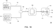
- FIG. 1D is a schematic diagram of power transmission in a high-speed mode of the hybrid power system in FIG. 1A .
- FIG. 2A is a schematic diagram of the optimized power operation of an engine generator of a hybrid electrical energy system in FIG. 1D .
- a hybrid power system 100 of the disclosure includes a transmission module 110, a motor 120, an electrical energy distributor 130, an engine generator 140, and an energy storage module 150.
- the motor 120 is connected to the transmission module 110.
- the electrical energy distributor 130 is coupled to the motor 120.
- the engine generator 140 is coupled to the electrical energy distributor 130 and is adapted to generate electrical energy.
- the energy storage module 150 is coupled to the electrical energy distributor 130 and is adapted to store electrical energy.
- the transmission module 110 is suitable for vehicle carriers and has a gear set 111, a differential 112, multiple rotating shafts 113, and a multiple tires 114.
- the gear set 111 is coupled to the motor 120 and configured to transmit power from the motor 120.
- the differential 112 is meshed with the gear set 111 to balance the difference between left and right tires during cornering to ensure vehicle stability and maneuverability.
- the rotating shafts 113 are disposed on opposite sides of the differential 112 and extend in an axial direction.
- the tires 114 are respectively mounted on the rotating shafts 113 and rotate with the rotating shafts 113.
- the motor 120 may convert electrical energy into mechanical energy, and generate kinetic energy by applying work to the transmission module 110 to drive the vehicle carrier.
- the engine generator 140 is adapted to burn fuel to convert chemical energy into mechanical energy, and then convert mechanical energy into electrical energy through electromagnetic induction.
- the energy storage module 150 includes multiple aluminum-ion batteries 151, in which the aluminum-ion batteries 151 are connected in series. Furthermore, the aluminum-ion batteries 151 are charged and discharged synchronously.
- the electrical energy distributor 130 is installed on a vehicle carrier and adjusts the operating status of the engine generator 140 and the energy storage module 150 according to the traveling speed of the vehicle carrier, so as to achieve the purpose of the hybrid power system 100 automatically switching the power supply source according to the driving status.
- the energy storage module 150 and the engine generator 140 are connected in parallel to the electrical energy distributor 130.
- the engine generator 140 when storage capacity of the energy storage module 150 is insufficient, the engine generator 140 is adapted to rotate at a constant speed to generate a first power P1, and the electrical energy distributor 130 provides the first power P1 to the motor 120 and the energy storage module. 150.
- the energy storage module 150 transmits a second power P2 to the motor 120 through the electrical energy distributor 130, and the electrical energy distributor 130 turns off the engine generator 140.
- the electrical energy distributor 130 turns off the engine generator 140 and the energy storage module 150 supplies the second power P2 to the motor 120.
- FIG. 2B is a schematic diagram of power convergence of an engine generator of the hybrid electrical energy system in FIG. 2A .
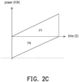
- FIG. 2C is a schematic diagram of power interaction between an energy storage module and the engine generator of the hybrid electrical energy system in FIG. 1D .
- the electrical energy distributor 130 turns on the engine generator 140 to provide the first power P1 to the motor 120 and the energy storage module 150.
- the hybrid power system 100 of the disclosure optimizes operating efficiency of the engine generator 140 to improve fuel utilization, and the energy storage module 150 serves as the main power source of the hybrid power system 100.
- the engine generator 140 is only charged when the electric quantity of the energy storage module 150 is insufficient and at the same time provides electrical energy to the motor 120 (see FIG. 2C ), so that the engine generator 140 is not turned on with the operation of the motor 120, and the engine generator 140 maintains a constant speed during the charging process (see FIG. 2B ) to maximize the efficiency of the engine generator 140.
- an operating speed of the engine generator 140 has converged to a single point, and the optimal rotational speed of the engine generator 140 shown in FIG. 2A is 3000 (rpm).
- the power output, fuel efficiency, and pollutant emissions are most effective at the optimal rotational speed of the engine generator 140, which may minimize the fuel consumption and emission pollutions of the engine generator 140, and thus the engine generator 140 is intended to maximize the conversion of the fuel energy into electrical energy and storage.
- FIG. 2D is a schematic diagram comparing the output power of an internal combustion engine and the power consumed by a motor of the hybrid electrical energy system in FIG. 2C .
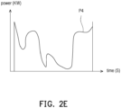
- FIG. 2E is a schematic diagram of the output power of the internal combustion engine minus the power consumed by the motor of the hybrid electrical energy system of FIG. 2D .
- the engine generator 140 rotates at a constant speed (3000 rpm shown in FIG. 2A ) to generate the first power P1.
- the motor 120 operates dynamically and has a motor consumption power P3 to consume a part of the first power P1, and the other part of the first power P1 is transmitted to the energy storage module 150 through the electrical energy distributor 130 to dynamically charge the energy storage module 150.
- this curve is a residual power P4 of the first power P1 minus the motor consumption power P3, and this residual power P4 will be transmitted to the energy storage module 150 through the electrical energy distributor 130.
- the disclosure raises the second power P2 of the energy storage module 150 to a level where it can directly supply the motor 120 to operate, so that the engine generator 140 can operate at a constant speed.
- the energy storage module 150 adopts aluminum ions and possesses the characteristic of quick charging and discharging, which may shorten the charging time of the energy storage module 150.
- the energy storage module 150 when the storage capacity of the energy storage module 150 is normal, the energy storage module 150 will fully supply the electrical energy required by the motor 120.
- the engine generator 140 when the storage capacity of the energy storage module 150 is insufficient, the engine generator 140 is turned on to supply electrical energy to the motor 120 and charges the energy storage module 150 at the same time. Based on the above, the rotational speed of the engine generator 140 is not affected by road conditions and power demand, the motor 120 will arbitrarily extract the first power P1 generated by the engine generator 140 to maintain operation, and the residual power P4 of the first power P1 minus the motor consumption power P3 will be fully recharged to the energy storage module 150.
- the vehicle carrier may still be driven normally without being affected.
- the hybrid power system of the disclosure is suitable for vehicles or similar carriers, and the hybrid power system combines an engine generator and an energy storage module as an electrical energy source.
- the engine generator is only used to generate electrical energy, and supplies part of the electrical energy to the motor to generate power, and the other part of the electrical energy is stored in the energy storage module.
- the electrical energy of the energy storage module is supplied to the motor through the electrical energy distributor to generate power.
- the disclosure only generates power through the motor, and according to the high-speed mode or low-speed mode of the motor, it will automatically switch to the engine generator to supply the electrical energy required by the motor or the energy storage module to supply the electrical energy required by the motor, so that sufficient electric power may be generated for the motor and the energy storage module at all speeds.
- the hybrid power system of the disclosure does not need to equip the engine generator with a power transmission mechanism, so the mounting position of the engine generator in the vehicle carrier is relatively flexible.
- the engine generator of the disclosure operates only at a constant speed to generate electrical energy, thereby improving fuel efficiency and reducing pollutant emissions.
- the disclosure has the advantage that the rotational speed and torque of the engine generator are not affected by the rotational speed or power demand of the vehicle carrier, and the engine generator is operated at a constant speed in the working zone with the highest energy efficiency right after the engine generator has been turned on, and the engine generator will continue to be operated until the energy storage module is full, so as to minimize the number of times of turning on of the engine generator.
- the fast-charging feature of the energy storage module may also reduce the running time of the engine generator.
Landscapes
- Engineering & Computer Science (AREA)
- Chemical & Material Sciences (AREA)
- Combustion & Propulsion (AREA)
- Transportation (AREA)
- Mechanical Engineering (AREA)
- Automation & Control Theory (AREA)
- Electric Propulsion And Braking For Vehicles (AREA)
- Connection Of Motors, Electrical Generators, Mechanical Devices, And The Like (AREA)
- Control Of Vehicle Engines Or Engines For Specific Uses (AREA)
- Hybrid Electric Vehicles (AREA)
Abstract
Description
- This disclosure relates to a power system, and in particular to a hybrid power system combining an engine and a battery.
- Existing fuel vehicles have the worst fuel efficiency at low speeds. Take Taipei City as an example, Taipei City has been developed for a long time, and the surrounding area is characterized by frequent commercial activities and high population density, which leads to the saturation of the number of motor vehicles. In addition, the roads in the urban area are narrow and there are a large number of traffic signals, so most of the vehicles in the urban area are traveling at low speeds, which is why the use of the existing fuel vehicles in the urban area will result in high fuel consumption and environmental pollution.
- In order to improve the shortcomings of the existing fuel vehicles, the development of hybrid electric vehicles, combining the advantages of electric vehicles and fuel vehicles, the internal combustion engine and motor of the hybrid vehicles can be automatically switched depending on the conditions at high speeds or low speeds. In short, at low speeds, the motor delivers power, while at high speeds, the internal combustion engine delivers power, thus avoiding the inefficiency of the internal combustion engine at low speeds.
- However, the existing hybrid electric vehicles have to be designed with two sets of transmission systems, resulting in high production costs and complicated methods of switching between high and low speeds.
- The disclosure provides a hybrid power system combining a rechargeable battery and an engine generator, capable of switching between the rechargeable battery or the engine generator to supply electrical energy to a motor at different electric quantities to enhance operating efficiency.
- The hybrid power system of the disclosure includes a transmission module, a motor, an electrical energy distributor, an engine generator, and an energy storage module. The motor is connected to the transmission module. The electrical energy distributor is coupled to the motor. The engine generator is coupled to the electrical energy distributor. The energy storage module is coupled to the electrical energy distributor. The engine generator is adapted to rotate at a constant speed to generate a first power, and the electrical energy distributor provides the first power to the motor and energy storage module.
- In an embodiment of the disclosure, when the motor switches to a low-speed mode or a high-speed mode, the energy storage module transmits a second power to the motor through the electrical energy distributor, and the electrical energy distributor turns off the engine generator.
- In an embodiment of the disclosure, when electric quantity of the energy storage module is higher than a predetermined value, the electrical energy distributor turns off the engine generator and the energy storage module supplies a second power to the motor.
- In an embodiment of the disclosure, when electric quantity of the energy storage module is lower than a predetermined value, the electrical energy distributor turns on the engine generator to provide the first power to the motor and the energy storage module.
- In an embodiment of the disclosure, the engine generator rotates at a constant speed, the motor operates dynamically to consume a part of the first power, and the other part of the first power is transmitted to the energy storage module through the electrical energy distributor to dynamically charge the energy storage module.
- In an embodiment of the disclosure, the energy storage module includes multiple aluminum-ion batteries.
- In an embodiment of the disclosure, the energy storage module and the engine generator are connected in parallel to the electrical energy distributor.
- In an embodiment of the disclosure, the transmission module has a gear set, a differential, a plurality of rotating shafts, and a plurality of tires, the gear set is coupled to the motor, the differential is meshed with the gear set, the rotating shafts are disposed on opposite sides of the differential and extend in an axial direction, and the tires are respectively mounted on the rotating shafts.
- Based on the above, the hybrid power system of the disclosure is suitable for vehicles or similar carriers, and the hybrid power system combines an engine generator and an energy storage module as an electrical energy source. The engine generator is only used to generate electrical energy, and supplies part of the electrical energy to the motor to generate power, and the other part of the electrical energy is stored in the energy storage module. The electrical energy of the energy storage module is supplied to the motor through the electrical energy distributor to generate power.
- As the disclosure only generates power through the motor, and according to the high-speed mode or low-speed mode of the motor, it will automatically switch to the engine generator to supply the electrical energy required by the motor or the energy storage module to supply the electrical energy required by the motor, so that sufficient electric power may be generated for the motor and the energy storage module at all speeds. Compared with the existing fuel-electricity hybrid power system which requires the design of two sets of transmission systems, the hybrid power system of the disclosure does not need to equip the engine generator with a power transmission mechanism, so the mounting position of the engine generator in the vehicle carrier is relatively flexible. In addition, the engine generator of the disclosure operates only at a constant speed in the high-speed mode to generate electrical energy, thereby improving fuel efficiency and reducing pollutant emissions
- To make the aforementioned more comprehensible, several embodiments accompanied with drawings are described in detail as follows.
- The accompanying drawings are included to provide a further understanding of the disclosure, and are incorporated in and constitute a part of this specification. The drawings illustrate example embodiments of the disclosure and, together with the description, serve to explain the principles of the disclosure.
-
FIG. 1A is a block diagram of a hybrid power system according to an embodiment of the disclosure. -
FIG. 1B is a block diagram of power transmission in a low-speed mode of the hybrid power system inFIG. 1A . -
FIG. 1C is a line diagram of power output of an energy storage module of the hybrid power system inFIG. 1B . -
FIG. 1D is a schematic diagram of power transmission in a high-speed mode of the hybrid power system inFIG. 1A . -
FIG. 2A is a schematic diagram of the optimized power operation of an engine generator of a hybrid electrical energy system inFIG. 1D . -
FIG. 2B is a schematic diagram of power convergence of an engine generator of the hybrid electrical energy system inFIG. 2A . -
FIG. 2C is a schematic diagram of power interaction between an energy storage module and the engine generator of the hybrid electrical energy system inFIG. 1D . -
FIG. 2D is a schematic diagram comparing the output power of an internal combustion engine and the power consumed by a motor of the hybrid electrical energy system inFIG. 2C . -
FIG. 2E is a schematic diagram of the output power of the internal combustion engine minus the power consumed by the motor of the hybrid electrical energy system ofFIG. 2D . -
FIG. 1A is a block diagram of a hybrid power system according to an embodiment of the disclosure. -
FIG. 1B is a block diagram of power transmission in a low-speed mode of the hybrid power system inFIG. 1A .FIG. 1C is a line diagram of power output of an energy storage module of the hybrid power system inFIG. 1B .FIG. 1D is a schematic diagram of power transmission in a high-speed mode of the hybrid power system inFIG. 1A .FIG. 2A is a schematic diagram of the optimized power operation of an engine generator of a hybrid electrical energy system inFIG. 1D . - Referring to
FIG. 1A , ahybrid power system 100 of the disclosure includes atransmission module 110, amotor 120, anelectrical energy distributor 130, anengine generator 140, and anenergy storage module 150. Themotor 120 is connected to thetransmission module 110. Theelectrical energy distributor 130 is coupled to themotor 120. Theengine generator 140 is coupled to theelectrical energy distributor 130 and is adapted to generate electrical energy. Theenergy storage module 150 is coupled to theelectrical energy distributor 130 and is adapted to store electrical energy. - In detail, the
transmission module 110 is suitable for vehicle carriers and has agear set 111, a differential 112, multiple rotatingshafts 113, and amultiple tires 114. The gear set 111 is coupled to themotor 120 and configured to transmit power from themotor 120. The differential 112 is meshed with the gear set 111 to balance the difference between left and right tires during cornering to ensure vehicle stability and maneuverability. The rotatingshafts 113 are disposed on opposite sides of the differential 112 and extend in an axial direction. Thetires 114 are respectively mounted on therotating shafts 113 and rotate with therotating shafts 113. - The
motor 120 may convert electrical energy into mechanical energy, and generate kinetic energy by applying work to thetransmission module 110 to drive the vehicle carrier. Theengine generator 140 is adapted to burn fuel to convert chemical energy into mechanical energy, and then convert mechanical energy into electrical energy through electromagnetic induction. Theenergy storage module 150 includes multiple aluminum-ion batteries 151, in which the aluminum-ion batteries 151 are connected in series. Furthermore, the aluminum-ion batteries 151 are charged and discharged synchronously. - For example, the
electrical energy distributor 130 is installed on a vehicle carrier and adjusts the operating status of theengine generator 140 and theenergy storage module 150 according to the traveling speed of the vehicle carrier, so as to achieve the purpose of thehybrid power system 100 automatically switching the power supply source according to the driving status. Theenergy storage module 150 and theengine generator 140 are connected in parallel to theelectrical energy distributor 130. - Referring to
FIG. 1D andFIG. 2A , when storage capacity of theenergy storage module 150 is insufficient, theengine generator 140 is adapted to rotate at a constant speed to generate a first power P1, and theelectrical energy distributor 130 provides the first power P1 to themotor 120 and the energy storage module. 150. - Referring to
FIG. 1B andFIG. 1C , when themotor 120 switches to a low-speed mode or a high-speed mode, theenergy storage module 150 transmits a second power P2 to themotor 120 through theelectrical energy distributor 130, and theelectrical energy distributor 130 turns off theengine generator 140. - With reference to
FIG. 1C , when electric quantity of theenergy storage module 150 is higher than a predetermined value, theelectrical energy distributor 130 turns off theengine generator 140 and theenergy storage module 150 supplies the second power P2 to themotor 120. -
FIG. 2B is a schematic diagram of power convergence of an engine generator of the hybrid electrical energy system inFIG. 2A .FIG. 2C is a schematic diagram of power interaction between an energy storage module and the engine generator of the hybrid electrical energy system inFIG. 1D . - Referring to
FIG. 2A to FIG. 2C , when the electric quantity of theenergy storage module 150 is lower than the predetermined value, theelectrical energy distributor 130 turns on theengine generator 140 to provide the first power P1 to themotor 120 and theenergy storage module 150. - In short, the
hybrid power system 100 of the disclosure optimizes operating efficiency of theengine generator 140 to improve fuel utilization, and theenergy storage module 150 serves as the main power source of thehybrid power system 100. Theengine generator 140 is only charged when the electric quantity of theenergy storage module 150 is insufficient and at the same time provides electrical energy to the motor 120 (seeFIG. 2C ), so that theengine generator 140 is not turned on with the operation of themotor 120, and theengine generator 140 maintains a constant speed during the charging process (seeFIG. 2B ) to maximize the efficiency of theengine generator 140. - Supplementally, referring to
FIG. 2A to FIG. 2C , an operating speed of theengine generator 140 has converged to a single point, and the optimal rotational speed of theengine generator 140 shown inFIG. 2A is 3000 (rpm). The power output, fuel efficiency, and pollutant emissions are most effective at the optimal rotational speed of theengine generator 140, which may minimize the fuel consumption and emission pollutions of theengine generator 140, and thus theengine generator 140 is intended to maximize the conversion of the fuel energy into electrical energy and storage. -
FIG. 2D is a schematic diagram comparing the output power of an internal combustion engine and the power consumed by a motor of the hybrid electrical energy system inFIG. 2C .FIG. 2E is a schematic diagram of the output power of the internal combustion engine minus the power consumed by the motor of the hybrid electrical energy system ofFIG. 2D . - Referring to
FIG. 2B andFIG. 2D , theengine generator 140 rotates at a constant speed (3000 rpm shown inFIG. 2A ) to generate the first power P1. Themotor 120 operates dynamically and has a motor consumption power P3 to consume a part of the first power P1, and the other part of the first power P1 is transmitted to theenergy storage module 150 through theelectrical energy distributor 130 to dynamically charge theenergy storage module 150. - In addition, the resistance and speed of the vehicle carrier during driving change dynamically, so the motor power consumption P3 of the
motor 120 presents an irregular curve. Referring toFIG. 2E , this curve is a residual power P4 of the first power P1 minus the motor consumption power P3, and this residual power P4 will be transmitted to theenergy storage module 150 through theelectrical energy distributor 130. - Since the disclosure raises the second power P2 of the
energy storage module 150 to a level where it can directly supply themotor 120 to operate, so that theengine generator 140 can operate at a constant speed. Compared to the existing technology where the change in the rotational speed of theengine generator 140 changes from a dynamic value to a fixed value, and a charging power of theenergy storage module 150 changes from a fixed value to a dynamic value, theenergy storage module 150 adopts aluminum ions and possesses the characteristic of quick charging and discharging, which may shorten the charging time of theenergy storage module 150. - Referring to
FIG. 1B andFIG. 1C , when the storage capacity of theenergy storage module 150 is normal, theenergy storage module 150 will fully supply the electrical energy required by themotor 120. - Referring to
FIG. 1D ,FIG. 2C , andFIG. 2D , when the storage capacity of theenergy storage module 150 is insufficient, theengine generator 140 is turned on to supply electrical energy to themotor 120 and charges theenergy storage module 150 at the same time. Based on the above, the rotational speed of theengine generator 140 is not affected by road conditions and power demand, themotor 120 will arbitrarily extract the first power P1 generated by theengine generator 140 to maintain operation, and the residual power P4 of the first power P1 minus the motor consumption power P3 will be fully recharged to theenergy storage module 150. - In short, when the
engine generator 140 dynamically charges theenergy storage module 150, the vehicle carrier may still be driven normally without being affected. - Based on the above, the hybrid power system of the disclosure is suitable for vehicles or similar carriers, and the hybrid power system combines an engine generator and an energy storage module as an electrical energy source. The engine generator is only used to generate electrical energy, and supplies part of the electrical energy to the motor to generate power, and the other part of the electrical energy is stored in the energy storage module. The electrical energy of the energy storage module is supplied to the motor through the electrical energy distributor to generate power.
- As the disclosure only generates power through the motor, and according to the high-speed mode or low-speed mode of the motor, it will automatically switch to the engine generator to supply the electrical energy required by the motor or the energy storage module to supply the electrical energy required by the motor, so that sufficient electric power may be generated for the motor and the energy storage module at all speeds. Compared with the existing fuel-electricity hybrid power system which requires the design of two sets of transmission systems, the hybrid power system of the disclosure does not need to equip the engine generator with a power transmission mechanism, so the mounting position of the engine generator in the vehicle carrier is relatively flexible. In addition, the engine generator of the disclosure operates only at a constant speed to generate electrical energy, thereby improving fuel efficiency and reducing pollutant emissions.
- Compared with the existing technology, the disclosure has the advantage that the rotational speed and torque of the engine generator are not affected by the rotational speed or power demand of the vehicle carrier, and the engine generator is operated at a constant speed in the working zone with the highest energy efficiency right after the engine generator has been turned on, and the engine generator will continue to be operated until the energy storage module is full, so as to minimize the number of times of turning on of the engine generator. In addition, the fast-charging feature of the energy storage module may also reduce the running time of the engine generator.
Claims (8)
- A hybrid power system (100), comprising:a transmission module (110);a motor, connected to the transmission module (110);an electrical energy distributor (130), coupled to the motor;an engine generator (140), coupled to the electrical energy distributor (130); andan energy storage module (150), coupled to the electrical energy distributor (130),wherein the engine generator (140) is adapted to rotate at a constant speed to generate a first power (P1), and the electrical energy distributor (130) provides the first power (P1) to the motor and the energy storage module (150).
- The hybrid power system (100) according to claim 1, wherein when the motor switches to a low-speed mode or a high-speed mode, the energy storage module (150) transmits a second power (P2) to the motor through the electrical energy distributor (130), and the electrical energy distributor (130) turns off the engine generator (140).
- The hybrid power system (100) according to claim 1, wherein when electric quantity of the energy storage module (150) is higher than a predetermined value, the electrical energy distributor (130) turns off the engine generator (140) and the energy storage module (150) supplies a second power (P2) to the motor.
- The hybrid power system (100) according to claim 1, wherein when electric quantity of the energy storage module (150) is lower than a predetermined value, the electrical energy distributor (130) turns on the engine generator (140) to provide the first power (P1) to the motor and the energy storage module (150).
- The hybrid power system (100) according to claim 1, wherein the engine generator (140) rotates at a constant speed, the motor operates dynamically to consume a part of the first power (P1), and the other part of the first power (P1) is transmitted to the energy storage module (150) through the electrical energy distributor (130) to dynamically charge the energy storage module (150).
- The hybrid power system (100) according to claim 1, wherein the energy storage module (150) comprises a plurality of aluminum-ion batteries (151).
- The hybrid power system (100) according to claim 1, wherein the energy storage module (150) and the engine generator (140) are connected in parallel to the electrical energy distributor (130).
- The hybrid power system (100) according to claim 1, wherein the transmission module (110) has a gear set (111), a differential, a plurality of rotating shafts (113), and a plurality of tires (114), the gear set (111) is coupled to the motor, the differential (112) is meshed with the gear set (111), the rotating shafts are disposed on opposite sides of the differential (112) and extend in an axial direction, and the tires (114) are respectively mounted on the rotating shafts (113).
Applications Claiming Priority (1)
| Application Number | Priority Date | Filing Date | Title |
|---|---|---|---|
| TW112128162A TWI862042B (en) | 2023-07-27 | 2023-07-27 | Hybrid power system |
Publications (1)
| Publication Number | Publication Date |
|---|---|
| EP4497619A1 true EP4497619A1 (en) | 2025-01-29 |
Family
ID=90922722
Family Applications (1)
| Application Number | Title | Priority Date | Filing Date |
|---|---|---|---|
| EP24172700.7A Withdrawn EP4497619A1 (en) | 2023-07-27 | 2024-04-26 | Hybrid power system |
Country Status (3)
| Country | Link |
|---|---|
| US (1) | US20250033630A1 (en) |
| EP (1) | EP4497619A1 (en) |
| TW (1) | TWI862042B (en) |
Citations (4)
| Publication number | Priority date | Publication date | Assignee | Title |
|---|---|---|---|---|
| US20100145589A1 (en) * | 2007-04-24 | 2010-06-10 | Mitsubishi Electric Corporation | Electric Drive System and Hybrid Drive System |
| US20170021714A1 (en) * | 2014-03-24 | 2017-01-26 | Toyota Jidosha Kabushiki Kaisha | Hybrid vehicle |
| WO2022183549A1 (en) * | 2021-03-02 | 2022-09-09 | 比亚迪股份有限公司 | Control method for hybrid vehicle, and vehicle control unit |
| US11535237B2 (en) * | 2019-06-14 | 2022-12-27 | Nissan Motor Co., Ltd. | Electric device control method and electric device |
Family Cites Families (3)
| Publication number | Priority date | Publication date | Assignee | Title |
|---|---|---|---|---|
| US6554088B2 (en) * | 1998-09-14 | 2003-04-29 | Paice Corporation | Hybrid vehicles |
| JP6521484B2 (en) * | 2017-02-23 | 2019-05-29 | マツダ株式会社 | Power control method and power control apparatus for hybrid vehicle |
| US12496893B2 (en) * | 2021-12-28 | 2025-12-16 | Cummins Inc. | Coupling arrangement for a generator set |
-
2023
- 2023-07-27 TW TW112128162A patent/TWI862042B/en active
-
2024
- 2024-04-26 EP EP24172700.7A patent/EP4497619A1/en not_active Withdrawn
- 2024-05-12 US US18/661,677 patent/US20250033630A1/en active Pending
Patent Citations (4)
| Publication number | Priority date | Publication date | Assignee | Title |
|---|---|---|---|---|
| US20100145589A1 (en) * | 2007-04-24 | 2010-06-10 | Mitsubishi Electric Corporation | Electric Drive System and Hybrid Drive System |
| US20170021714A1 (en) * | 2014-03-24 | 2017-01-26 | Toyota Jidosha Kabushiki Kaisha | Hybrid vehicle |
| US11535237B2 (en) * | 2019-06-14 | 2022-12-27 | Nissan Motor Co., Ltd. | Electric device control method and electric device |
| WO2022183549A1 (en) * | 2021-03-02 | 2022-09-09 | 比亚迪股份有限公司 | Control method for hybrid vehicle, and vehicle control unit |
Also Published As
| Publication number | Publication date |
|---|---|
| TW202504778A (en) | 2025-02-01 |
| TWI862042B (en) | 2024-11-11 |
| US20250033630A1 (en) | 2025-01-30 |
Similar Documents
| Publication | Publication Date | Title |
|---|---|---|
| CN204161081U (en) | A kind of range extended electric vehicle power system in parallel | |
| CN103921667B (en) | Hybrid power system | |
| CN108839551B (en) | Hybrid power system and control method | |
| CN110816253B (en) | Gear ring-free planetary gear train hybrid power system | |
| CN102019847A (en) | Series-parallel connection hybrid power driving system | |
| CN102358162B (en) | Hybrid oil-electricity energy-saving power device and control method thereof | |
| EP4497619A1 (en) | Hybrid power system | |
| CN202806344U (en) | Solar-energy gas-electric hybrid power system for middle bus | |
| CN203246312U (en) | Magnetism-stress coupled parallel-axis-type parallel structured hybrid power system of automobile | |
| CN201021113Y (en) | Tandem hybrid power electric car power supply device installed with energy-storage flywheel | |
| CN107054044B (en) | Hybrid vehicle driving device and control method thereof | |
| CN109677395A (en) | A kind of hybrid power system of extended-range mixed power electric car | |
| RU199685U1 (en) | INTELLIGENT DEVICE FOR CHARGING AND POWER SUPPLY OF VEHICLES | |
| CN204161080U (en) | A kind of power system of electric automobile | |
| CN101648511B (en) | Control method of engine speed of hybrid car in generating state | |
| CN202965991U (en) | Electric vehicle with fuel oil for auxiliary electricity generation | |
| CN202243043U (en) | A plug-in electric vehicle with range-extending function | |
| CN203246317U (en) | Magnetism-stress coupled coaxial-type parallel-structured hybrid power system of automobile | |
| CN203246316U (en) | Magnetism-stress coupled series-structured hybrid power system of automobile | |
| CN203198761U (en) | Power system of power balance type pure-electric-drive electric vehicle | |
| CN203344733U (en) | Engine and motor-combined driven automobile hybrid power system | |
| CN208216514U (en) | A kind of pure electric vehicle dynamical system | |
| CN110789365A (en) | Electric commercial vehicle and motor control method | |
| CN103231647B (en) | Coaxial-type hybrid connected structure hybrid power system for automobile and the mixed method of magnetic couple | |
| CN103231646A (en) | Magnetism-stress coupling parallel-shaft parallel structure automobile hybrid power system and method |
Legal Events
| Date | Code | Title | Description |
|---|---|---|---|
| PUAI | Public reference made under article 153(3) epc to a published international application that has entered the european phase |
Free format text: ORIGINAL CODE: 0009012 |
|
| STAA | Information on the status of an ep patent application or granted ep patent |
Free format text: STATUS: REQUEST FOR EXAMINATION WAS MADE |
|
| 17P | Request for examination filed |
Effective date: 20240426 |
|
| AK | Designated contracting states |
Kind code of ref document: A1 Designated state(s): AL AT BE BG CH CY CZ DE DK EE ES FI FR GB GR HR HU IE IS IT LI LT LU LV MC ME MK MT NL NO PL PT RO RS SE SI SK SM TR |
|
| STAA | Information on the status of an ep patent application or granted ep patent |
Free format text: STATUS: EXAMINATION IS IN PROGRESS |
|
| 17Q | First examination report despatched |
Effective date: 20251218 |
|
| STAA | Information on the status of an ep patent application or granted ep patent |
Free format text: STATUS: THE APPLICATION HAS BEEN WITHDRAWN |
|
| 18W | Application withdrawn |
Effective date: 20260316 |