EP4496019A1 - Manufacturing apparatus - Google Patents
Manufacturing apparatus Download PDFInfo
- Publication number
- EP4496019A1 EP4496019A1 EP23770513.2A EP23770513A EP4496019A1 EP 4496019 A1 EP4496019 A1 EP 4496019A1 EP 23770513 A EP23770513 A EP 23770513A EP 4496019 A1 EP4496019 A1 EP 4496019A1
- Authority
- EP
- European Patent Office
- Prior art keywords
- metal foil
- pressure bonding
- bonding roller
- pair
- protrusion
- Prior art date
- Legal status (The legal status is an assumption and is not a legal conclusion. Google has not performed a legal analysis and makes no representation as to the accuracy of the status listed.)
- Pending
Links
Images



Classifications
-
- B—PERFORMING OPERATIONS; TRANSPORTING
- B23—MACHINE TOOLS; METAL-WORKING NOT OTHERWISE PROVIDED FOR
- B23K—SOLDERING OR UNSOLDERING; WELDING; CLADDING OR PLATING BY SOLDERING OR WELDING; CUTTING BY APPLYING HEAT LOCALLY, e.g. FLAME CUTTING; WORKING BY LASER BEAM
- B23K20/00—Non-electric welding by applying impact or other pressure, with or without the application of heat, e.g. cladding or plating
- B23K20/04—Non-electric welding by applying impact or other pressure, with or without the application of heat, e.g. cladding or plating by means of a rolling mill
-
- B—PERFORMING OPERATIONS; TRANSPORTING
- B23—MACHINE TOOLS; METAL-WORKING NOT OTHERWISE PROVIDED FOR
- B23K—SOLDERING OR UNSOLDERING; WELDING; CLADDING OR PLATING BY SOLDERING OR WELDING; CUTTING BY APPLYING HEAT LOCALLY, e.g. FLAME CUTTING; WORKING BY LASER BEAM
- B23K20/00—Non-electric welding by applying impact or other pressure, with or without the application of heat, e.g. cladding or plating
- B23K20/26—Auxiliary equipment
-
- H—ELECTRICITY
- H01—ELECTRIC ELEMENTS
- H01M—PROCESSES OR MEANS, e.g. BATTERIES, FOR THE DIRECT CONVERSION OF CHEMICAL ENERGY INTO ELECTRICAL ENERGY
- H01M4/00—Electrodes
- H01M4/02—Electrodes composed of, or comprising, active material
- H01M4/04—Processes of manufacture in general
- H01M4/0402—Methods of deposition of the material
- H01M4/0404—Methods of deposition of the material by coating on electrode collectors
-
- H—ELECTRICITY
- H01—ELECTRIC ELEMENTS
- H01M—PROCESSES OR MEANS, e.g. BATTERIES, FOR THE DIRECT CONVERSION OF CHEMICAL ENERGY INTO ELECTRICAL ENERGY
- H01M4/00—Electrodes
- H01M4/02—Electrodes composed of, or comprising, active material
- H01M4/04—Processes of manufacture in general
- H01M4/043—Processes of manufacture in general involving compressing or compaction
- H01M4/0435—Rolling or calendering
-
- H—ELECTRICITY
- H01—ELECTRIC ELEMENTS
- H01M—PROCESSES OR MEANS, e.g. BATTERIES, FOR THE DIRECT CONVERSION OF CHEMICAL ENERGY INTO ELECTRICAL ENERGY
- H01M4/00—Electrodes
- H01M4/02—Electrodes composed of, or comprising, active material
- H01M4/13—Electrodes for accumulators with non-aqueous electrolyte, e.g. for lithium-accumulators; Processes of manufacture thereof
- H01M4/139—Processes of manufacture
- H01M4/1395—Processes of manufacture of electrodes based on metals, Si or alloys
-
- H—ELECTRICITY
- H01—ELECTRIC ELEMENTS
- H01M—PROCESSES OR MEANS, e.g. BATTERIES, FOR THE DIRECT CONVERSION OF CHEMICAL ENERGY INTO ELECTRICAL ENERGY
- H01M4/00—Electrodes
- H01M4/02—Electrodes composed of, or comprising, active material
- H01M4/64—Carriers or collectors
- H01M4/66—Selection of materials
- H01M4/661—Metal or alloys, e.g. alloy coatings
-
- B—PERFORMING OPERATIONS; TRANSPORTING
- B23—MACHINE TOOLS; METAL-WORKING NOT OTHERWISE PROVIDED FOR
- B23K—SOLDERING OR UNSOLDERING; WELDING; CLADDING OR PLATING BY SOLDERING OR WELDING; CUTTING BY APPLYING HEAT LOCALLY, e.g. FLAME CUTTING; WORKING BY LASER BEAM
- B23K2101/00—Articles made by soldering, welding or cutting
- B23K2101/16—Bands or sheets of indefinite length
-
- B—PERFORMING OPERATIONS; TRANSPORTING
- B23—MACHINE TOOLS; METAL-WORKING NOT OTHERWISE PROVIDED FOR
- B23K—SOLDERING OR UNSOLDERING; WELDING; CLADDING OR PLATING BY SOLDERING OR WELDING; CUTTING BY APPLYING HEAT LOCALLY, e.g. FLAME CUTTING; WORKING BY LASER BEAM
- B23K2101/00—Articles made by soldering, welding or cutting
- B23K2101/36—Electric or electronic devices
-
- B—PERFORMING OPERATIONS; TRANSPORTING
- B23—MACHINE TOOLS; METAL-WORKING NOT OTHERWISE PROVIDED FOR
- B23K—SOLDERING OR UNSOLDERING; WELDING; CLADDING OR PLATING BY SOLDERING OR WELDING; CUTTING BY APPLYING HEAT LOCALLY, e.g. FLAME CUTTING; WORKING BY LASER BEAM
- B23K2103/00—Materials to be soldered, welded or cut
- B23K2103/18—Dissimilar materials
Definitions
- the present disclosure relates to a manufacturing apparatus that manufactures an electrode plate.
- a negative electrode current collector in a secondary battery such as a lithium ion battery is manufactured by arranging a lithium foil on a copper foil. For example, a lithium foil is cut to a predetermined dimension, holes are drilled at regular intervals on a negative electrode current collector surface, an adhesive is applied to the hole, and the cut lithium foil is transferred to the hole of the negative electrode current collector (see, for example, Patent Literature 1).
- Patent Literature 1 JP H6-150935
- the present disclosure addresses the issue described above, and a purpose thereof is to provide a technology for improving the accuracy of manufacturing of an electrode plate.
- a manufacturing apparatus includes: a pair of pressure bonding rollers each having a cylindrical shape.
- a first metal foil and a second metal foil stacked are inserted between the pair of rollers, the first metal foil and the second metal foil are pressure bonded by a rotation of the pair of pressure bonding rollers, and the pair of pressure bonding rollers include a first pressure bonding roller provided on a side of the first metal foil and a second pressure bonding roller different from the first pressure bonding roller.
- the first pressure bonding roller includes a D-cut surface at least in a portion of the cylindrical shape.
- a protrusion is provided in each of two boundaries between a side surface and the D-cut surface of the cylindrical shape in the first pressure bonding roller.
- the accuracy of manufacturing of an electrode plate can be improved.
- Figs. 1A-1B show the structure of a cylindrical battery 1.
- Fig. 1A is a cross-sectional view of the cylindrical battery 1
- Fig. 1B is an exploded perspective view of an electrode group 2.
- the cylindrical battery 1 is, for example, a rechargeable secondary battery such as a lithium ion battery, a nickel-metal hydride battery, and a nickelcadmium battery.
- the cylindrical battery 1 by way of one example has a structure in which the electrode group 2 is stored in an outer can 4 along with an electrolytic solution (not shown).
- the electrode group 2 is cylindrical in shape by way of one example and, as shown in Fig.
- the separator 10 is formed by a microporous film made of, by way of one example, a polypropylene resin or the like.
- the first electrode plate 6 and the second electrode plate 8 have a structure in which an electrode active material layer is stacked on a current collector.
- the current collector is comprised of an aluminum foil or the like when it is a positive electrode and is comprised of a copper foil or the like when it is a negative electrode.
- the electrode active material layer can be formed by applying an electrode mixture material to the surface of the current collector by a known coating apparatus and drying and rolling the material.
- the electrode mixture material is obtained by kneading materials including an electrode active material, a binder, a conductive material, etc. in a dispersion medium and uniformly dispersing the materials.
- the electrode active material is lithium cobalt oxide, lithium iron phosphate, or the like when it is a positive electrode and is graphite or the like when it is a negative electrode.
- the first electrode plate 6 has a first electrode core member 12 that is not coated with an electrode mixture material at the end on one side in the width direction A (a direction that intersects the longitudinal direction of the belt).
- the width direction A is also referred to as "vertical direction”.
- the side of the first electrode plate 6 on which the first electrode core member 12 is disposed by the "upper side” the side of the first electrode plate 6 on which the first electrode core member 12 is not disposed is called the "lower side”.
- the first electrode core member 12 is an exposed portion of the current collector of the first electrode plate 6 in which the electrode active material layer is not stacked.
- the second electrode plate 8 has a second electrode core member 14 not coated with an electrode mixture material on the other side in the width direction A, i.e., at the end opposite to the side where the first electrode core member 12 protrudes. It can be said that the second electrode core member 14 is disposed on the lower side of the second electrode plate 8. The second electrode core member 14 is an exposed portion of the current collector of the second electrode plate 8 in which the electrode active material layer is not stacked.
- the electrode group 2 has a structure in which the first electrode plate 6 and the second electrode plate 8 are wound. For this reason, a plurality of ends of the first electrode plate 6 and the second electrode plate 8 in the width direction A are arranged in the radial direction B of the electrode group 2. Therefore, the electrode group 2 includes a plurality of first electrode core members 12 arranged in the radial direction B and a plurality of second electrode core members 14 arranged in the radial direction B.
- each first electrode core member 12 is bent toward the central axis C of the winding of the electrode group 2, i.e., bent inward in the radial direction B.
- the central axis C of the winding is, for example, the geometric center of the outline of the electrode group 2 seen in the width direction A, i.e., the geometric center of the outline of the shape of the electrode group 2 projected in the width direction A.
- the ends (the second electrode core member 14) of a plurality of second electrode plates 8 arranged in the radial direction B are bent in the radial direction B.
- each second electrode core member 14 is bent toward the central axis C of the winding.
- a first current collector plate 20 is provided on the side in the electrode group 2 where the first electrode core member 12 protrudes, i.e., toward the upper side of the electrode group 2.
- the first current collector plate 20 is made of, for example, aluminum or the like.
- the first electrode core member 12 of the plurality of first electrode plates 6 bent on the upper side are placed in surface contact with the first current collector plate 20.
- Laser welding, etc. of the first current collector plate 20 and the first electrode core member 12 forms a first welded part 30. Thereby, the first electrode plate 6 of each winding layer and the first current collector plate 20 are joined to each other in the first welded part 30.
- a second current collector plate 22 is provided on the side in the electrode group 2 where the second electrode core member 14 protrudes, i.e., on the lower side of the electrode group 2.
- the second current collector plate 22 is made of, for example, copper, nickel, nickel-plated copper, nickel-plated iron, and the like.
- the second electrode core member 14 of the plurality of second electrode plates 8 bent on the lower side are in surface contact with the second current collector plate 22.
- Laser welding, etc. of the second current collector plate 22 with the second electrode core member 14 forms a second welded part 32. Thereby, the second electrode plate 8 of each winding layer and the second current collector plate 22 are joined to each other in the second welded part 32.
- the electrode group 2 to which the first current collector plate 20 and the second current collector plate 22 are joined is stored in the bottomed cylindrical outer can 4 along with the electrolytic solution.
- the outer can 4 is made of, for example, copper, nickel, iron, an alloy thereof, or the like.
- the second current collector plate 22 is joined to the inner bottom surface of the outer can 4 by welding or the like.
- the first current collector plate 20 is joined to a sealing plate 26 made of the same metal as the outer can 4 by welding or the like.
- the sealing plate 26 is fitted into the opening of the outer can 4 via an insulating gasket 24. Thereby, the electrode group 2 and the electrolytic solution are sealed in the outer can 4.
- FIG. 2 is a side view showing a structure of a manufacturing apparatus 180.
- a first metal foil roll member 100 has a first metal foil 200 wrapped around it.
- the first metal foil 200 is a lithium foil (about 10 um) that is a negative electrode active material.
- the second metal foil roll member 102 has a second metal foil 202 wrapped around it.
- the second metal foil 202 is a copper foil (about 13 um) that is a negative electrode current collector.
- the third metal foil roll member 104 has a third metal foil 204 wrapped around it.
- the third metal foil 204 is a lithium foil (about 10 um) that is a negative electrode active material.
- the first metal foil 200 and the second metal foil 202 are different metals, and the first metal foil 200 and the third metal foil 204 are the same metal.
- the width of the second metal foil 202 is narrower than the width of the first metal foil 200 and the width of the third metal foil 204.
- the first metal foil 200 is drawn from the first metal foil roll member 100
- the second metal foil 202 is drawn from the second metal foil roll member 102
- the third metal foil 204 is drawn from the third metal foil roll member 104.
- the first metal foil 200, the second metal foil 202, and the third metal foil 204 travel toward a first pressure bonding roller 110 and a second pressure bonding roller 112 forming a pair of pressure bonding rollers. In that process, the first metal foil 200, the second metal foil 202, and the third metal foil 204 are stacked in that order from top to bottom.
- the first pressure bonding roller 110 and the second pressure bonding roller 112 are arranged in the vertical direction. To describe it specifically, the first pressure bonding roller 110 is provided on the side of the first metal foil 200, and the second pressure bonding roller 112 is provided on the side of the third metal foil 204.
- the first metal foil 200, the second metal foil 202, and the third metal foil 204 stacked are inserted between the first pressure bonding roller 110 and the second pressure bonding roller 112.
- the first pressure bonding roller 110 and the second pressure bonding roller 112 have a cylindrical shape and are rotatable.
- the first metal foil 200, the second metal foil 202, and the third metal foil 204 are pressure bonded by the rotation of the first pressure bonding roller 110 and the second pressure bonding roller 112.
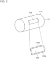
- Fig. 3 is a perspective view showing a structure of the first pressure bonding roller 110.
- the first pressure bonding roller 110 has a cylindrical shape and is covered with a side surface 114.
- a D-cut surface 116 is formed on a portion of the side surface 114.
- a first protrusion 118a and a second protrusion 118b are respectively provided in the two boundaries between the side surface 114 and the D-cut surface 116.
- the first protrusion 118a and the second protrusion 118b are collectively referred to as a protrusion 118.
- the protrusion 118 has, for example, a semi-cylindrical shape or a triangular prism shape.
- the height of the protrusion 118 from the side surface 114 is 20% to 70% and, preferably, 50%, of the thickness of the first metal foil 200.
- the height of the protrusion 118 may be varied by a spring.
- the second pressure bonding roller 112 also has the same structure as the first pressure bonding roller 110.
- the second pressure bonding roller 112 is provided with a third protrusion (not shown) similar to the first protrusion 118a and with a fourth protrusion (not shown) similar to the second protrusion 118b.
- the third and fourth processes are collectively referred to as a protrusion.
- the height of the protrusion of the second pressure bonding roller 112 is 20% to 70% and, preferably, 50%, of the thickness of the third metal foil 204. Reference is made back to Fig. 2 .
- the timing of pressure bonding by the protrusion 118 of the first pressure bonding roller 110 and the timing of pressure bonding by the protrusion (not shown) of the second pressure bonding roller 112 are synchronized. This is equivalent to the time when the D-cut surface 116 of the first pressure bonding roller 110 pressure-bonds the first metal foil 200 and the time when the D-cut surface (not shown) of the second pressure bonding roller 112 pressure-bonds the third metal foil 204 coinciding.
- a vertical alignment jig is used, but a description thereof is omitted here.
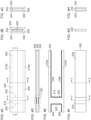
- Figs. 4A-4H show a structure of a laminated body manufactured by the manufacturing apparatus 180.
- Fig. 4A is a top view of the first metal foil 200, the second metal foil 202 (not shown), and the third metal foil 204 (not shown) pressure bonded by the first pressure bonding roller 110 and the second pressure bonding roller 112 as viewed from the side of the first metal foil 200 side.
- a first boundary 300 is formed by the first protrusion 118a of the first pressure bonding roller 110 and the third protrusion of the second pressure bonding roller 112, and a second boundary 302 is formed by the second protrusion 118b of the first pressure bonding roller 110 and the fourth protrusion of the second pressure bonding roller 112.
- the first boundary 300 and the second boundary 302 are formed not only in the first metal foil 200 but also in the third metal foil 204. That is, each protrusion forms the first boundary 300 and the second boundary 302 by molding. In that process, the height of each protrusion is set as described above in consideration of the impact on the second metal foil 202.
- This portion represents an interval portion 212.
- pressure bonding is performed by the side surface 114 of the first pressure bonding roller 110 and the side surface (not shown) of the second pressure bonding roller 112.
- the pressure bonding force of the interval portion 212 is weaker than the pressure bonding force of the portions other than the interval portion 212. That is, pressure bonding of the first metal foil 200 through the third metal foil 204 and formation of the interval portion 212 are both performed in a series of steps.
- Fig. 4B is a cross-sectional view in A-A' direction of Fig. 4A , that is, a cross-sectional view of the interval portion 212.
- a weakly pressure bonded portion 220 is provided between the first metal foil 200 and the second metal foil 202, and a weakly pressure bonded portion 220 is also provided between the second metal foil 202 and the third metal foil 204.
- the weakly pressure bonded portion 220 is a portion with a weak pressure bonding force.
- a portion, of the first metal foil 200 and the third metal foil 204, in contact with one end of the second metal foil 202 is a third boundary 304, and a portion in contact with another end of the second metal foil 202 is a fourth boundary 306.
- the third boundary 304 and the fourth boundary 306 are also provided in the third metal foil 204.
- a portion outside the third boundary 304 is a first surplus portion 210a
- a portion outside the fourth boundary 306 is a second surplus portion 210b.
- the first surplus portion 210a and the second surplus portion 210b are collectively referred to as a surplus portion 210.
- the surplus portion 210 is a portion protruding from the second metal foil 202 and is a portion that does not adhere to the second metal foil 202.
- Fig. 4C is a cross-sectional view in B-B' direction of Fig. 4A .
- the first metal foil 200, the second metal foil 202, and the third metal foil 204 are stacked, and the weakly pressure bonded portion 220 is not provided.
- Fig. 4D is a cross-sectional view in C-C' direction of Fig. 4A .
- the weakly pressure bonded portion 220 is provided only in the interval portion 212, and the weakly pressure bonded portion 220 is not provided in the portions other than the interval portion 212.
- Figs. 4E-4H will be described later, and reference is made back to Fig. 2 .
- a first adhesive tape feed 120 has a first adhesive tape 240 wrapped around it.
- a second adhesive tape feed 122 has a second adhesive tape 242 wrapped around it.
- the first adhesive tape 240 is drawn from the first adhesive tape feed 120
- the second adhesive tape 242 is drawn from the second adhesive tape feed 122.
- the first adhesive tape 240 has a width equal to or greater than the width of the first metal foil 200 and has an adhesive surface on the side of the first metal foil 200.
- the second adhesive tape 242 has a width equal to or greater than the width of the third metal foil 204 and has an adhesive surface on the third metal foil 204 side.
- the first adhesive tape 240, the laminated body of the first metal foil 200 through the third metal foil 204, and the second adhesive tape 242 travel toward a first pressing roller 130 and a second pressing roller 132 forming a pair of pressing rollers. In that process, the first adhesive tape 240, the laminated body of the first metal foil 200 through the third metal foil 204, and the second adhesive tape 242 are stacked in that order from top to bottom.
- the first pressing roller 130 and the second pressing roller 132 are arranged in the vertical direction. To describe it specifically, the first pressing roller 130 is provided on the side of the first adhesive tape 240, and the second pressing roller 132 is provided on the side of the second adhesive tape 242.
- the first adhesive tape 240, the laminated body of the first metal foil 200 through the third metal foil 204, and the second adhesive tape 242 are inserted between the first pressing roller 130 and the second pressing roller 132.
- the first pressing roller 130 and the second pressing roller 132 have a cylindrical shape and are rotatable.
- the first adhesive tape 240 adheres to the first metal foil 200
- the second adhesive tape 242 adheres to the third metal foil 204 by the rotation of the first pressing roller 130 and the second pressing roller 132.
- a first adhesive tape take-up 140 takes up the first adhesive tape 240 from the first pressing roller 130 and the second pressing roller 132
- a second adhesive tape take-up 142 takes up the second adhesive tape 242 from the first pressing roller 130 and the second pressing roller 132.
- the first adhesive tape 240 peels off the portion of the first metal foil 200 that has a weak pressure bonding force with respect to the second metal foil 202, i.e., the surplus portion 210 and the interval portion 212, from the first metal foil 200. Further, by adhesion between the second adhesive tape 242 and the third metal foil 204, the second adhesive tape 242 peels off the portion of the third metal foil 204 that has a weak pressure bonding force with respect to the second metal foil 202, i.e., the surplus portion 210 and the interval portion 212 from the third metal foil 204.
- the first boundary 300 and the second boundary 302 provided in the first metal foil 200 and the third metal foil 204 will have a small depth. If the depth of the first boundary 300 and the second boundary 302 is shallow, the boundary of the interval portion 212 will be difficult to peel off, and a warp may be created in the boundary of the interval portion 212 when the interval portion 212 is peeled off by the first adhesive tape 240 and the second adhesive tape 242.
- the first boundary 300 and the second boundary 302 provided in the first metal foil 200 and the third metal foil 204 will have a large depth. Given a large depth of the first boundary 300 and the second boundary 302, the boundary of the interval portion 212 is easily peeled off, and a warp is created less easily in the boundary of the interval portion 212 when the interval portion 212 is peeled off by the first adhesive tape 240 and the second adhesive tape 242.
- Fig. 4E shows a portion of the first metal foil 200 that has been peeled off by the first adhesive tape 240. As shown, the surplus portion 210 and the interval portion 212 are peeled off. The portion of the third metal foil 204 peeled off by the second adhesive tape 242 will also be as shown in Fig. 4E.
- Fig. 4F shows an electrode plate 280, i.e., a laminated body that remains after the first metal foil 200 and the third metal foil 204 as shown in Fig. 4E have been peeled off.
- the second metal foil 202 is exposed from a portion of the first metal foil 200.
- the second metal foil 202 is also exposed from a portion of the third metal foil 204, although it is not shown here.
- FIG. 4G is a D-D' cross-sectional view of Fig. 4F , which includes only the second metal foil 202.
- Fig. 4H is an E-E' cross-sectional view of Fig. 4F , in which the first metal foil 200, the second metal foil 202, and the third metal foil 204 are stacked.
- a plurality of second electrode plates 8 are produced by cutting the electrode plate 280 into a plurality of pieces.
- the first pressure bonding roller 110 and the second pressure bonding roller 112 are provided with the D-cut surface 116 and the protrusion 118 so that pressure bonding of the first metal foil 200 through the third metal foil 204 and formation of the interval portion 212 are both performed in a series of steps. Further, pressure bonding of the first metal foil 200 through the third metal foil 204 and formation of the interval portion 212 are both performed in a series of steps so that misalignment is prevented when the interval portion 212 is formed. Further, misalignment is prevented when the interval portion 212 is formed so that the accuracy of manufacturing of the electrode plate 280 can be improved.
- the height of the protrusions in the first pressure bonding roller 110 and the second pressure bonding roller 112 are configured to be 20% to 70% of the thickness of the first metal foil 200 and the third metal foil 204 so that it is possible to reduce the impact on the second metal foil 202, while also ensuring a sufficient depth of the first boundary 300 and the second boundary 302. Further, the timing of pressure bonding by the protrusion 118 of the first pressure bonding roller 110 and the timing of pressure bonding by the protrusion of the second pressure bonding roller 112 are synchronized so that the positions of the interval portions 212 in the first metal foil 200 and the third metal foil 204 can be aligned.
- the first metal foil 200 and the third metal foil 204 are pressure bonded to both surfaces of the second metal foil 202.
- the first metal foil 200 is pressure bonded to one surface of the second metal foil 202
- the third metal foil 204 is not pressure bonded to the second metal foil 202.
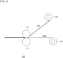
- Fig. 5 is a side view showing a structure of a manufacturing apparatus 182.
- the first metal foil roll member 100 and the second metal foil roll member 102 are the same as those of Fig. 2 .
- the manufacturing apparatus 182 does not include the third metal foil roll member 104.
- the first metal foil 200 is drawn from the first metal foil roll member 100
- the second metal foil 202 is drawn from the second metal foil roll member 102.
- the first metal foil 200 and the second metal foil 202 travel toward the first pressure bonding roller 110 and the second pressure bonding roller 112 forming a pair of pressure bonding rollers. In that process, the first metal foil 200 and the second metal foil 202 are stacked from top to bottom in that order.
- the first pressure bonding roller 110 and the second pressure bonding roller 112 are arranged in the vertical direction.
- the first pressure bonding roller 110 is provided on the side of the first metal foil 200
- the second pressure bonding roller 112 is provided on the side of the second metal foil 202.
- the first metal foil 200 and the second metal foil 202 stacked are inserted between the first pressure bonding roller 110 and the second pressure bonding roller 112.
- the first metal foil 200 and the second metal foil 202 are pressure bonded by the rotation of the first pressure bonding roller 110 and the second pressure bonding roller 112.
- the first pressure bonding roller 110 is provided with the D-cut surface 116 and the protrusion 118.
- the second pressure bonding roller 112 is not provided with a D-cut surface and a protrusion, and a side surface (not shown) is provided.
- the D-cut surface 116 and the protrusion 118 of the first pressure bonding roller 110 form the surplus portion 210 and the interval portion 212 in the first metal foil 200.
- the surplus portion 210 and the interval portion 212 are peeled off by the first adhesive tape 240.
- the D-cut surface 116 and the protrusion 118 are provided in the first pressure bonding roller 110, and a D-cut surface is not provided in the second pressure bonding roller 112 so that pressure-bonding of the first metal foil 200 and the second metal foil 202 and formation of the interval portion 212 in the first metal foil 200 can both be performed in a series of steps. Further, pressure bonding of the first metal foil 200 and the third metal foil 204 and formation of the interval portion 212 in the first metal foil 200 are both performed in a series of steps so that misalignment is prevented when the interval portion 212 is formed. Further, misalignment is prevented when the interval portion 212 is formed so that the accuracy of manufacturing of the electrode plate 280 can be improved.
- the height of the first pressure bonding roller 110 is configured to be 20% to 70% of the thickness of the first metal foil 200 so that it is possible to reduce the impact on the second metal foil 202, while also ensuring a sufficient depth of the first boundary 300 and the second boundary 302.
- embodiment 3 the first pressure bonding roller 110 and the second pressure bonding roller 112 is caused to pressure-bond the first metal foil 200 and the third metal foil 204 on both surfaces of the second metal foil 202 and to form the surplus portion 210 and the interval portion 212 in the first metal foil 200 and the third metal foil 204.
- the arrangement of the pressure bonding rollers is different from that of embodiment 1. The description below highlights a difference from the foregoing.
- Fig. 6 is a side view showing a structure of a manufacturing apparatus 184.
- the first metal foil roll member 100, the second metal foil roll member 102, and the third metal foil roll member 104 are as shown in Fig. 2 .
- the first metal foil 200 is drawn from the first metal foil roll member 100
- the second metal foil 202 is drawn from the second metal foil roll member 102
- the third metal foil 204 is drawn from the third metal foil roll member 104.
- the first metal foil 200, the second metal foil 202, and the third metal foil 204 travel toward the first pressure bonding roller 110 and the second pressure bonding roller 112 forming a pair of pressure bonding rollers. In that process, the first metal foil 200, the second metal foil 202, and the third metal foil 204 are stacked from top to bottom in that order.
- the first pressure bonding roller 110 and the second pressure bonding roller 112 are arranged in the vertical direction. To describe it specifically, the first pressure bonding roller 110 is provided on the side of the first metal foil 200, and the second pressure bonding roller 112 is provided on the side of the third metal foil 204.
- the first metal foil 200, the second metal foil 202, and the third metal foil 204 stacked are inserted between the first pressure bonding roller 110 and the second pressure bonding roller 112.
- the first pressure bonding roller 110 and the second pressure bonding roller 112 have a cylindrical shape and are rotatable.
- the first metal foil 200, the second metal foil 202, and the third metal foil 204 are pressure bonded by the rotation of the first pressure bonding roller 110 and the second pressure bonding roller 112.
- the first pressure bonding roller 110 is provided with the D-cut surface 116 and the protrusion 118.
- the second pressure bonding roller 112 is not provided with a D-cut surface and a protrusion, and a side surface (not shown) is provided.
- the D-cut surface 116 and the protrusion 118 of the first pressure bonding roller 110 form the surplus portion 210 and the interval portion 212 in the first metal foil 200.
- first pressure bonding roller 110 and the second pressure bonding roller 112 are defined as a pair of pressure bonding rollers in the front stage
- a third pressure bonding roller 150 and a fourth pressure bonding roller 152 are referred to as a pair of pressure bonding rollers in the rear stage.
- the first metal foil 200, the second metal foil 202, and the third metal foil 204 that are pressure bonded travel toward the third pressure bonding roller 150 and the fourth pressure bonding roller 152 forming a pair of pressure bonding rollers.
- the third pressure bonding roller 150 and the fourth pressure bonding roller 152 are arranged in the vertical direction. To describe it specifically, the third pressure bonding roller 150 is provided on the side of the first metal foil 200, and the fourth pressure bonding roller 152 is provided on the side of the third metal foil 204.
- the first metal foil 200, the second metal foil 202, and the third metal foil 204 that are pressure bonded are inserted between the third pressure bonding roller 150 and the fourth pressure bonding roller 152.
- the third pressure bonding roller 150 and the fourth pressure bonding roller 152 have a cylindrical shape and are rotatable.
- the first metal foil 200, the second metal foil 202, and the third metal foil 204 are further pressure bonded by the rotation of the third pressure bonding roller 150 and the fourth pressure bonding roller 152.
- the third pressure bonding roller 150 is not provided with a D-cut surface and a protrusion, and a side surface (not shown) is provided.
- a D-cut surface (not shown) and a protrusion (not shown) are provided in a portion of the side surface (not shown) of the fourth pressure bonding roller 152.
- the D-cut surface and the protrusion of the fourth pressure bonding roller 152 form the surplus portion 210 and the interval portion 212 in the third metal foil 204.
- the area of the D-cut surface 116 in the first pressure bonding roller 110 of embodiment 1 is the same as the area of the D-cut surface in the second pressure bonding roller 112.
- the area of the interval portion 212 provided in the first metal foil 200 and the area of the interval portion 212 provided in the third metal foil 204 are also the same.
- the area of the D-cut surface 116 in the first pressure bonding roller 110 of embodiment 3 may be smaller than the area of the D-cut surface in the fourth pressure bonding roller 152. Therefore, the area of the interval portion 212 provided in the first metal foil 200 may be smaller than the area of the interval portion 212 provided in the third metal foil 204.
- the third pressure bonding roller 150 and the fourth pressure bonding roller 152 are provided to follow the first pressure bonding roller 110 and the second pressure bonding roller 112, formation of the interval portion 212 in the first metal foil 200 and formation of the interval portion 212 in the third metal foil 204 can be timed differently. Further, formation of the interval portion 212 in the first metal foil 200 and formation of the interval portion 212 in the third metal foil 204 are timed differently so that the flexibility in the configuration can be improved.
- the area of the D-cut surface 116 in the first pressure bonding roller 110 is configured to be smaller than the area of the D-cut surface in the fourth pressure bonding roller 152 so that the area of the interval portion 212 in the first metal foil 200 can be configured to be smaller than the area of the interval portion 212 in the third metal foil 204. Further, the area of the interval portion 212 in the first metal foil 200 is configured to be smaller than the area of the interval portion 212 in the third metal foil 204 so that the flexibility in the configuration can be improved.
- the height of the protrusions in the first pressure bonding roller 110 and the fourth pressure bonding roller 152 are configured to be 20% to 70% of the thickness of the first metal foil 200 and the third metal foil 204 so that it is possible to reduce the impact on the second metal foil 202, while also ensuring a sufficient depth of the first boundary 300 and the second boundary 302.
- the embodiments may be defined by the following items.
- manufacturing accuracy of an electrode plate can be improved.
- a width direction, B radial direction, C central axis of the winding, D direction of winding, 1 cylindrical battery, 2 electrode group, 4 outer can, 6 first electrode plate, 8 second electrode plate, 10 separator, 12 first electrode core member, 14 second electrode core member, 20 first current collector plate, 22 second current collector plate, 24 insulating gasket, 26 sealing plate, 30 first welded part, 32 second welded part, 100 first metal foil roll member, 102 second metal foil roll member, 104 third metal foil roll member, 110 first pressure bonding roller, 112 second pressure bonding roller, 114 side surface, 116 D-cut surface, 118 protrusion, 120 first adhesive tape feed, 122 second adhesive tape feed, 130 first pressing roller, 132 second pressing roller, 140 first adhesive tape take-up, 142 second adhesive tape take-up, 150 third pressure bonding roller, 152 fourth pressure bonding roller, 180, 182, 184 manufacturing apparatus, 200 first metal foil, 202 second metal foil, 204 third metal foil, 210 surplus portion, 212 interval portion, 220 weakly pressure bonded
Landscapes
- Engineering & Computer Science (AREA)
- Chemical & Material Sciences (AREA)
- Chemical Kinetics & Catalysis (AREA)
- Electrochemistry (AREA)
- General Chemical & Material Sciences (AREA)
- Mechanical Engineering (AREA)
- Manufacturing & Machinery (AREA)
- Materials Engineering (AREA)
- Battery Electrode And Active Subsutance (AREA)
- Connection Of Batteries Or Terminals (AREA)
Abstract
Description
- The present disclosure relates to a manufacturing apparatus that manufactures an electrode plate.
- A negative electrode current collector in a secondary battery such as a lithium ion battery is manufactured by arranging a lithium foil on a copper foil. For example, a lithium foil is cut to a predetermined dimension, holes are drilled at regular intervals on a negative electrode current collector surface, an adhesive is applied to the hole, and the cut lithium foil is transferred to the hole of the negative electrode current collector (see, for example, Patent Literature 1).
- Patent Literature 1:
JP H6-150935 - When the cut lithium foil is transferred to the hole of the negative electrode current collector, misalignment that occurs when the lithium foil is transferred to the hole of the negative electrode current collector presents a problem.
- The present disclosure addresses the issue described above, and a purpose thereof is to provide a technology for improving the accuracy of manufacturing of an electrode plate.
- A manufacturing apparatus according to an embodiment of the present disclosure includes: a pair of pressure bonding rollers each having a cylindrical shape. A first metal foil and a second metal foil stacked are inserted between the pair of rollers, the first metal foil and the second metal foil are pressure bonded by a rotation of the pair of pressure bonding rollers, and the pair of pressure bonding rollers include a first pressure bonding roller provided on a side of the first metal foil and a second pressure bonding roller different from the first pressure bonding roller. The first pressure bonding roller includes a D-cut surface at least in a portion of the cylindrical shape. A protrusion is provided in each of two boundaries between a side surface and the D-cut surface of the cylindrical shape in the first pressure bonding roller.
- According to the present disclosure, the accuracy of manufacturing of an electrode plate can be improved.
-
- [
Fig. 1] Figs. 1A-1B show the structure of acylindrical battery 1 according toembodiment 1. - [
Fig. 2] Fig. 2 is a side view showing a structure of a manufacturing apparatus according toembodiment 1. - [
Fig. 3] Fig. 3 is a perspective view showing a structure of the first pressure bonding roller ofFig. 2 . - [
Fig. 4] Figs. 4A-4H show a structure of a laminated body manufactured by the manufacturing apparatus ofFig. 2 . - [
Fig. 5] Fig. 5 is a side view showing a structure of a manufacturing apparatus according toembodiment 2. - [
Fig. 6] Fig. 6 is a side view showing a structure of a manufacturing apparatus according to embodiment 3. - Hereinafter, the present disclosure will be described based on preferred embodiments with reference to drawings. The embodiments do not limit the scope of the present disclosure but exemplify the disclosure. Not all of the features and the combinations thereof described in the embodiments are necessarily essential to the present disclosure. Identical or like constituting elements, members, processes shown in the drawings are represented by identical symbols and a duplicate description will be omitted as appropriate. The scales and shapes of the parts shown in the drawings are defined for convenience's sake to make the explanation easy and shall not be interpreted in a limitative manner unless otherwise specified. Terms like "first", "second", etc. used in the specification and claims do not indicate an order or importance by any means unless specified otherwise and are used to distinguish a certain feature from the others. Those of the members that are not material to the description of the embodiments are omitted in the drawings.
- Hereinafter, (1) the structure of a cylindrical battery, (2) the structure of manufacturing apparatus and manufacturing process will be described in that order.
-
Figs. 1A-1B show the structure of acylindrical battery 1.Fig. 1A is a cross-sectional view of thecylindrical battery 1, andFig. 1B is an exploded perspective view of anelectrode group 2. Thecylindrical battery 1 is, for example, a rechargeable secondary battery such as a lithium ion battery, a nickel-metal hydride battery, and a nickelcadmium battery. Thecylindrical battery 1 by way of one example has a structure in which theelectrode group 2 is stored in anouter can 4 along with an electrolytic solution (not shown). Theelectrode group 2 is cylindrical in shape by way of one example and, as shown inFig. 1B , has a winding structure in which a belt-likefirst electrode plate 6 and a belt-likesecond electrode plate 8 are stacked, sandwiching a belt-like separator 10, and are wound in a spiral shape. In this embodiment, thefirst electrode plate 6 is the positive electrode plate and thesecond electrode plate 8 is the negative electrode plate, but the polarity of thefirst electrode plate 6 and thesecond electrode plate 8 may be reversed. Theseparator 10 is formed by a microporous film made of, by way of one example, a polypropylene resin or the like. - The
first electrode plate 6 and thesecond electrode plate 8 have a structure in which an electrode active material layer is stacked on a current collector. In the case of a general lithium ion secondary battery, the current collector is comprised of an aluminum foil or the like when it is a positive electrode and is comprised of a copper foil or the like when it is a negative electrode. The electrode active material layer can be formed by applying an electrode mixture material to the surface of the current collector by a known coating apparatus and drying and rolling the material. The electrode mixture material is obtained by kneading materials including an electrode active material, a binder, a conductive material, etc. in a dispersion medium and uniformly dispersing the materials. In the case of a general lithium ion secondary battery, the electrode active material is lithium cobalt oxide, lithium iron phosphate, or the like when it is a positive electrode and is graphite or the like when it is a negative electrode. - The
first electrode plate 6 has a firstelectrode core member 12 that is not coated with an electrode mixture material at the end on one side in the width direction A (a direction that intersects the longitudinal direction of the belt). Hereinafter, the width direction A is also referred to as "vertical direction". Further, denoting the side of thefirst electrode plate 6 on which the firstelectrode core member 12 is disposed by the "upper side", the side of thefirst electrode plate 6 on which the firstelectrode core member 12 is not disposed is called the "lower side". The firstelectrode core member 12 is an exposed portion of the current collector of thefirst electrode plate 6 in which the electrode active material layer is not stacked. Further, thesecond electrode plate 8 has a secondelectrode core member 14 not coated with an electrode mixture material on the other side in the width direction A, i.e., at the end opposite to the side where the firstelectrode core member 12 protrudes. It can be said that the secondelectrode core member 14 is disposed on the lower side of thesecond electrode plate 8. The secondelectrode core member 14 is an exposed portion of the current collector of thesecond electrode plate 8 in which the electrode active material layer is not stacked. - As described above, the
electrode group 2 has a structure in which thefirst electrode plate 6 and thesecond electrode plate 8 are wound. For this reason, a plurality of ends of thefirst electrode plate 6 and thesecond electrode plate 8 in the width direction A are arranged in the radial direction B of theelectrode group 2. Therefore, theelectrode group 2 includes a plurality of firstelectrode core members 12 arranged in the radial direction B and a plurality of secondelectrode core members 14 arranged in the radial direction B. - In the
electrode group 2, the ends (the first electrode core member 12) of a plurality offirst electrode plates 6 arranged in the radial direction B are bent in the radial direction B. For example, each firstelectrode core member 12 is bent toward the central axis C of the winding of theelectrode group 2, i.e., bent inward in the radial direction B. The central axis C of the winding is, for example, the geometric center of the outline of theelectrode group 2 seen in the width direction A, i.e., the geometric center of the outline of the shape of theelectrode group 2 projected in the width direction A. Further, in theelectrode group 2, the ends (the second electrode core member 14) of a plurality ofsecond electrode plates 8 arranged in the radial direction B are bent in the radial direction B. For example, each secondelectrode core member 14 is bent toward the central axis C of the winding. - A first
current collector plate 20 is provided on the side in theelectrode group 2 where the firstelectrode core member 12 protrudes, i.e., toward the upper side of theelectrode group 2. The firstcurrent collector plate 20 is made of, for example, aluminum or the like. The firstelectrode core member 12 of the plurality offirst electrode plates 6 bent on the upper side are placed in surface contact with the firstcurrent collector plate 20. By bending the firstelectrode core member 12 of eachfirst electrode plate 6, the contact area between each firstelectrode core member 12 and the firstcurrent collector plate 20 increases. Laser welding, etc. of the firstcurrent collector plate 20 and the firstelectrode core member 12 forms a first weldedpart 30. Thereby, thefirst electrode plate 6 of each winding layer and the firstcurrent collector plate 20 are joined to each other in the first weldedpart 30. - A second
current collector plate 22 is provided on the side in theelectrode group 2 where the secondelectrode core member 14 protrudes, i.e., on the lower side of theelectrode group 2. The secondcurrent collector plate 22 is made of, for example, copper, nickel, nickel-plated copper, nickel-plated iron, and the like. The secondelectrode core member 14 of the plurality ofsecond electrode plates 8 bent on the lower side are in surface contact with the secondcurrent collector plate 22. By bending the secondelectrode core member 14 of eachsecond electrode plate 8, the contact area between each secondelectrode core member 14 and the secondcurrent collector plate 22 increases. Laser welding, etc. of the secondcurrent collector plate 22 with the secondelectrode core member 14 forms a second weldedpart 32. Thereby, thesecond electrode plate 8 of each winding layer and the secondcurrent collector plate 22 are joined to each other in the second weldedpart 32. - The
electrode group 2 to which the firstcurrent collector plate 20 and the secondcurrent collector plate 22 are joined is stored in the bottomed cylindrical outer can 4 along with the electrolytic solution. Theouter can 4 is made of, for example, copper, nickel, iron, an alloy thereof, or the like. The secondcurrent collector plate 22 is joined to the inner bottom surface of theouter can 4 by welding or the like. The firstcurrent collector plate 20 is joined to a sealingplate 26 made of the same metal as theouter can 4 by welding or the like. The sealingplate 26 is fitted into the opening of theouter can 4 via an insulatinggasket 24. Thereby, theelectrode group 2 and the electrolytic solution are sealed in theouter can 4. - Hereinafter, an apparatus and a process for manufacturing a
second electrode plate 8, which is a negative electrode plate, will be described.Fig. 2 is a side view showing a structure of amanufacturing apparatus 180. A first metalfoil roll member 100 has afirst metal foil 200 wrapped around it. Thefirst metal foil 200 is a lithium foil (about 10 um) that is a negative electrode active material. The second metalfoil roll member 102 has asecond metal foil 202 wrapped around it. Thesecond metal foil 202 is a copper foil (about 13 um) that is a negative electrode current collector. The third metalfoil roll member 104 has athird metal foil 204 wrapped around it. Thethird metal foil 204 is a lithium foil (about 10 um) that is a negative electrode active material. Therefore, thefirst metal foil 200 and thesecond metal foil 202 are different metals, and thefirst metal foil 200 and thethird metal foil 204 are the same metal. For example, the width of thesecond metal foil 202 is narrower than the width of thefirst metal foil 200 and the width of thethird metal foil 204. - The
first metal foil 200 is drawn from the first metalfoil roll member 100, thesecond metal foil 202 is drawn from the second metalfoil roll member 102, and thethird metal foil 204 is drawn from the third metalfoil roll member 104. Thefirst metal foil 200, thesecond metal foil 202, and thethird metal foil 204 travel toward a firstpressure bonding roller 110 and a secondpressure bonding roller 112 forming a pair of pressure bonding rollers. In that process, thefirst metal foil 200, thesecond metal foil 202, and thethird metal foil 204 are stacked in that order from top to bottom. - The first
pressure bonding roller 110 and the secondpressure bonding roller 112 are arranged in the vertical direction. To describe it specifically, the firstpressure bonding roller 110 is provided on the side of thefirst metal foil 200, and the secondpressure bonding roller 112 is provided on the side of thethird metal foil 204. Thefirst metal foil 200, thesecond metal foil 202, and thethird metal foil 204 stacked are inserted between the firstpressure bonding roller 110 and the secondpressure bonding roller 112. The firstpressure bonding roller 110 and the secondpressure bonding roller 112 have a cylindrical shape and are rotatable. Thefirst metal foil 200, thesecond metal foil 202, and thethird metal foil 204 are pressure bonded by the rotation of the firstpressure bonding roller 110 and the secondpressure bonding roller 112. -
Fig. 3 is a perspective view showing a structure of the firstpressure bonding roller 110. The firstpressure bonding roller 110 has a cylindrical shape and is covered with aside surface 114. A D-cutsurface 116 is formed on a portion of theside surface 114. Afirst protrusion 118a and asecond protrusion 118b are respectively provided in the two boundaries between theside surface 114 and the D-cutsurface 116. Thefirst protrusion 118a and thesecond protrusion 118b are collectively referred to as a protrusion 118. The protrusion 118 has, for example, a semi-cylindrical shape or a triangular prism shape. The height of the protrusion 118 from theside surface 114 is 20% to 70% and, preferably, 50%, of the thickness of thefirst metal foil 200. The height of the protrusion 118 may be varied by a spring. - The second
pressure bonding roller 112 also has the same structure as the firstpressure bonding roller 110. The secondpressure bonding roller 112 is provided with a third protrusion (not shown) similar to thefirst protrusion 118a and with a fourth protrusion (not shown) similar to thesecond protrusion 118b. The third and fourth processes are collectively referred to as a protrusion. The height of the protrusion of the secondpressure bonding roller 112 is 20% to 70% and, preferably, 50%, of the thickness of thethird metal foil 204. Reference is made back toFig. 2 . - In the first
pressure bonding roller 110 and the secondpressure bonding roller 112, the timing of pressure bonding by the protrusion 118 of the firstpressure bonding roller 110 and the timing of pressure bonding by the protrusion (not shown) of the secondpressure bonding roller 112 are synchronized. This is equivalent to the time when the D-cutsurface 116 of the firstpressure bonding roller 110 pressure-bonds thefirst metal foil 200 and the time when the D-cut surface (not shown) of the secondpressure bonding roller 112 pressure-bonds thethird metal foil 204 coinciding. It can also be said that the time when thefirst protrusion 118a of the firstpressure bonding roller 110 pressure-bonds thefirst metal foil 200 coincides with the time when the third protrusion of the secondpressure bonding roller 112 pressure-bonds thethird metal foil 204. It can also be said that the time when thesecond protrusion 118b of the firstpressure bonding roller 110 pressure-bonds thefirst metal foil 200 coincides with the time when the fourth protrusion of the secondpressure bonding roller 112 pressure-bonds thethird metal foil 204. For such synchronization of the firstpressure bonding roller 110 and the secondpressure bonding roller 112, a vertical alignment jig is used, but a description thereof is omitted here. -
Figs. 4A-4H show a structure of a laminated body manufactured by themanufacturing apparatus 180.Fig. 4A is a top view of thefirst metal foil 200, the second metal foil 202 (not shown), and the third metal foil 204 (not shown) pressure bonded by the firstpressure bonding roller 110 and the secondpressure bonding roller 112 as viewed from the side of thefirst metal foil 200 side. Afirst boundary 300 is formed by thefirst protrusion 118a of the firstpressure bonding roller 110 and the third protrusion of the secondpressure bonding roller 112, and asecond boundary 302 is formed by thesecond protrusion 118b of the firstpressure bonding roller 110 and the fourth protrusion of the secondpressure bonding roller 112. Thefirst boundary 300 and thesecond boundary 302 are formed not only in thefirst metal foil 200 but also in thethird metal foil 204. That is, each protrusion forms thefirst boundary 300 and thesecond boundary 302 by molding. In that process, the height of each protrusion is set as described above in consideration of the impact on thesecond metal foil 202. - Between the
first boundary 300 and thesecond boundary 302, pressure bonding by the D-cutsurface 116 of the firstpressure bonding roller 110 and the D-cut surface (not shown) of the secondpressure bonding roller 112 is performed. This portion represents aninterval portion 212. In the other portions, on the other hand, pressure bonding is performed by theside surface 114 of the firstpressure bonding roller 110 and the side surface (not shown) of the secondpressure bonding roller 112. The pressure bonding force of theinterval portion 212 is weaker than the pressure bonding force of the portions other than theinterval portion 212. That is, pressure bonding of thefirst metal foil 200 through thethird metal foil 204 and formation of theinterval portion 212 are both performed in a series of steps. -
Fig. 4B is a cross-sectional view in A-A' direction ofFig. 4A , that is, a cross-sectional view of theinterval portion 212. A weakly pressure bondedportion 220 is provided between thefirst metal foil 200 and thesecond metal foil 202, and a weakly pressure bondedportion 220 is also provided between thesecond metal foil 202 and thethird metal foil 204. The weakly pressure bondedportion 220 is a portion with a weak pressure bonding force. - As shown in
Fig. 4A , a portion, of thefirst metal foil 200 and thethird metal foil 204, in contact with one end of thesecond metal foil 202 is athird boundary 304, and a portion in contact with another end of thesecond metal foil 202 is afourth boundary 306. Thethird boundary 304 and thefourth boundary 306 are also provided in thethird metal foil 204. A portion outside thethird boundary 304 is afirst surplus portion 210a, and a portion outside thefourth boundary 306 is asecond surplus portion 210b. Thefirst surplus portion 210a and thesecond surplus portion 210b are collectively referred to as a surplus portion 210. The surplus portion 210 is a portion protruding from thesecond metal foil 202 and is a portion that does not adhere to thesecond metal foil 202. -
Fig. 4C is a cross-sectional view in B-B' direction ofFig. 4A . Thefirst metal foil 200, thesecond metal foil 202, and thethird metal foil 204 are stacked, and the weakly pressure bondedportion 220 is not provided.Fig. 4D is a cross-sectional view in C-C' direction ofFig. 4A . As described above, the weakly pressure bondedportion 220 is provided only in theinterval portion 212, and the weakly pressure bondedportion 220 is not provided in the portions other than theinterval portion 212.Figs. 4E-4H will be described later, and reference is made back toFig. 2 . - A first
adhesive tape feed 120 has a firstadhesive tape 240 wrapped around it. A secondadhesive tape feed 122 has a secondadhesive tape 242 wrapped around it. The firstadhesive tape 240 is drawn from the firstadhesive tape feed 120, and the secondadhesive tape 242 is drawn from the secondadhesive tape feed 122. The firstadhesive tape 240 has a width equal to or greater than the width of thefirst metal foil 200 and has an adhesive surface on the side of thefirst metal foil 200. Further, the secondadhesive tape 242 has a width equal to or greater than the width of thethird metal foil 204 and has an adhesive surface on thethird metal foil 204 side. The firstadhesive tape 240, the laminated body of thefirst metal foil 200 through thethird metal foil 204, and the secondadhesive tape 242 travel toward a firstpressing roller 130 and a secondpressing roller 132 forming a pair of pressing rollers. In that process, the firstadhesive tape 240, the laminated body of thefirst metal foil 200 through thethird metal foil 204, and the secondadhesive tape 242 are stacked in that order from top to bottom. - The first
pressing roller 130 and the secondpressing roller 132 are arranged in the vertical direction. To describe it specifically, the firstpressing roller 130 is provided on the side of the firstadhesive tape 240, and the secondpressing roller 132 is provided on the side of the secondadhesive tape 242. The firstadhesive tape 240, the laminated body of thefirst metal foil 200 through thethird metal foil 204, and the secondadhesive tape 242 are inserted between the firstpressing roller 130 and the secondpressing roller 132. The firstpressing roller 130 and the secondpressing roller 132 have a cylindrical shape and are rotatable. The firstadhesive tape 240 adheres to thefirst metal foil 200, and the secondadhesive tape 242 adheres to thethird metal foil 204 by the rotation of the firstpressing roller 130 and the secondpressing roller 132. A first adhesive tape take-up 140 takes up the firstadhesive tape 240 from the firstpressing roller 130 and the secondpressing roller 132, and a second adhesive tape take-up 142 takes up the secondadhesive tape 242 from the firstpressing roller 130 and the secondpressing roller 132. - By such adhesion between the first
adhesive tape 240 and thefirst metal foil 200, the firstadhesive tape 240 peels off the portion of thefirst metal foil 200 that has a weak pressure bonding force with respect to thesecond metal foil 202, i.e., the surplus portion 210 and theinterval portion 212, from thefirst metal foil 200. Further, by adhesion between the secondadhesive tape 242 and thethird metal foil 204, the secondadhesive tape 242 peels off the portion of thethird metal foil 204 that has a weak pressure bonding force with respect to thesecond metal foil 202, i.e., the surplus portion 210 and theinterval portion 212 from thethird metal foil 204. - In the case the first
pressure bonding roller 110 and the secondpressure bonding roller 112 are not provided with the protrusion 118, thefirst boundary 300 and thesecond boundary 302 provided in thefirst metal foil 200 and thethird metal foil 204 will have a small depth. If the depth of thefirst boundary 300 and thesecond boundary 302 is shallow, the boundary of theinterval portion 212 will be difficult to peel off, and a warp may be created in the boundary of theinterval portion 212 when theinterval portion 212 is peeled off by the firstadhesive tape 240 and the secondadhesive tape 242. On the other hand, in the case the protrusion 118 provided in the firstpressure bonding roller 110 and the secondpressure bonding roller 112, as in this embodiment, thefirst boundary 300 and thesecond boundary 302 provided in thefirst metal foil 200 and thethird metal foil 204 will have a large depth. Given a large depth of thefirst boundary 300 and thesecond boundary 302, the boundary of theinterval portion 212 is easily peeled off, and a warp is created less easily in the boundary of theinterval portion 212 when theinterval portion 212 is peeled off by the firstadhesive tape 240 and the secondadhesive tape 242. -
Fig. 4E shows a portion of thefirst metal foil 200 that has been peeled off by the firstadhesive tape 240. As shown, the surplus portion 210 and theinterval portion 212 are peeled off. The portion of thethird metal foil 204 peeled off by the secondadhesive tape 242 will also be as shown inFig. 4E. Fig. 4F shows anelectrode plate 280, i.e., a laminated body that remains after thefirst metal foil 200 and thethird metal foil 204 as shown inFig. 4E have been peeled off. Thesecond metal foil 202 is exposed from a portion of thefirst metal foil 200. Thesecond metal foil 202 is also exposed from a portion of thethird metal foil 204, although it is not shown here.Fig. 4G is a D-D' cross-sectional view ofFig. 4F , which includes only thesecond metal foil 202.Fig. 4H is an E-E' cross-sectional view ofFig. 4F , in which thefirst metal foil 200, thesecond metal foil 202, and thethird metal foil 204 are stacked. A plurality ofsecond electrode plates 8 are produced by cutting theelectrode plate 280 into a plurality of pieces. - According to this embodiment, the first
pressure bonding roller 110 and the secondpressure bonding roller 112 are provided with the D-cutsurface 116 and the protrusion 118 so that pressure bonding of thefirst metal foil 200 through thethird metal foil 204 and formation of theinterval portion 212 are both performed in a series of steps. Further, pressure bonding of thefirst metal foil 200 through thethird metal foil 204 and formation of theinterval portion 212 are both performed in a series of steps so that misalignment is prevented when theinterval portion 212 is formed. Further, misalignment is prevented when theinterval portion 212 is formed so that the accuracy of manufacturing of theelectrode plate 280 can be improved. - Further, the height of the protrusions in the first
pressure bonding roller 110 and the secondpressure bonding roller 112 are configured to be 20% to 70% of the thickness of thefirst metal foil 200 and thethird metal foil 204 so that it is possible to reduce the impact on thesecond metal foil 202, while also ensuring a sufficient depth of thefirst boundary 300 and thesecond boundary 302. Further, the timing of pressure bonding by the protrusion 118 of the firstpressure bonding roller 110 and the timing of pressure bonding by the protrusion of the secondpressure bonding roller 112 are synchronized so that the positions of theinterval portions 212 in thefirst metal foil 200 and thethird metal foil 204 can be aligned. - A description will now be given of
embodiment 2. In theelectrode plate 280 according toembodiment 1, thefirst metal foil 200 and thethird metal foil 204 are pressure bonded to both surfaces of thesecond metal foil 202. In the electrode plate according toembodiment 2, on the other hand, thefirst metal foil 200 is pressure bonded to one surface of thesecond metal foil 202, and thethird metal foil 204 is not pressure bonded to thesecond metal foil 202. The description below highlights a difference fromembodiment 1. -
Fig. 5 is a side view showing a structure of amanufacturing apparatus 182. The first metalfoil roll member 100 and the second metalfoil roll member 102 are the same as those ofFig. 2 . Themanufacturing apparatus 182 does not include the third metalfoil roll member 104. Thefirst metal foil 200 is drawn from the first metalfoil roll member 100, and thesecond metal foil 202 is drawn from the second metalfoil roll member 102. Thefirst metal foil 200 and thesecond metal foil 202 travel toward the firstpressure bonding roller 110 and the secondpressure bonding roller 112 forming a pair of pressure bonding rollers. In that process, thefirst metal foil 200 and thesecond metal foil 202 are stacked from top to bottom in that order. - The first
pressure bonding roller 110 and the secondpressure bonding roller 112 are arranged in the vertical direction. To describe it specifically, the firstpressure bonding roller 110 is provided on the side of thefirst metal foil 200, and the secondpressure bonding roller 112 is provided on the side of thesecond metal foil 202. Thefirst metal foil 200 and thesecond metal foil 202 stacked are inserted between the firstpressure bonding roller 110 and the secondpressure bonding roller 112. Thefirst metal foil 200 and thesecond metal foil 202 are pressure bonded by the rotation of the firstpressure bonding roller 110 and the secondpressure bonding roller 112. As inembodiment 1, the firstpressure bonding roller 110 is provided with the D-cutsurface 116 and the protrusion 118. On the other hand, the secondpressure bonding roller 112 is not provided with a D-cut surface and a protrusion, and a side surface (not shown) is provided. - The D-cut
surface 116 and the protrusion 118 of the firstpressure bonding roller 110 form the surplus portion 210 and theinterval portion 212 in thefirst metal foil 200. The surplus portion 210 and theinterval portion 212 are peeled off by the firstadhesive tape 240. - According to this embodiment, the D-cut
surface 116 and the protrusion 118 are provided in the firstpressure bonding roller 110, and a D-cut surface is not provided in the secondpressure bonding roller 112 so that pressure-bonding of thefirst metal foil 200 and thesecond metal foil 202 and formation of theinterval portion 212 in thefirst metal foil 200 can both be performed in a series of steps. Further, pressure bonding of thefirst metal foil 200 and thethird metal foil 204 and formation of theinterval portion 212 in thefirst metal foil 200 are both performed in a series of steps so that misalignment is prevented when theinterval portion 212 is formed. Further, misalignment is prevented when theinterval portion 212 is formed so that the accuracy of manufacturing of theelectrode plate 280 can be improved. Further, the height of the firstpressure bonding roller 110 is configured to be 20% to 70% of the thickness of thefirst metal foil 200 so that it is possible to reduce the impact on thesecond metal foil 202, while also ensuring a sufficient depth of thefirst boundary 300 and thesecond boundary 302. - A description will now be given of embodiment 3. In
embodiment 1, the firstpressure bonding roller 110 and the secondpressure bonding roller 112 is caused to pressure-bond thefirst metal foil 200 and thethird metal foil 204 on both surfaces of thesecond metal foil 202 and to form the surplus portion 210 and theinterval portion 212 in thefirst metal foil 200 and thethird metal foil 204. In embodiment 3, the arrangement of the pressure bonding rollers is different from that ofembodiment 1. The description below highlights a difference from the foregoing. -
Fig. 6 is a side view showing a structure of amanufacturing apparatus 184. The first metalfoil roll member 100, the second metalfoil roll member 102, and the third metalfoil roll member 104 are as shown inFig. 2 . Thefirst metal foil 200 is drawn from the first metalfoil roll member 100, thesecond metal foil 202 is drawn from the second metalfoil roll member 102, and thethird metal foil 204 is drawn from the third metalfoil roll member 104. Thefirst metal foil 200, thesecond metal foil 202, and thethird metal foil 204 travel toward the firstpressure bonding roller 110 and the secondpressure bonding roller 112 forming a pair of pressure bonding rollers. In that process, thefirst metal foil 200, thesecond metal foil 202, and thethird metal foil 204 are stacked from top to bottom in that order. - The first
pressure bonding roller 110 and the secondpressure bonding roller 112 are arranged in the vertical direction. To describe it specifically, the firstpressure bonding roller 110 is provided on the side of thefirst metal foil 200, and the secondpressure bonding roller 112 is provided on the side of thethird metal foil 204. Thefirst metal foil 200, thesecond metal foil 202, and thethird metal foil 204 stacked are inserted between the firstpressure bonding roller 110 and the secondpressure bonding roller 112. The firstpressure bonding roller 110 and the secondpressure bonding roller 112 have a cylindrical shape and are rotatable. Thefirst metal foil 200, thesecond metal foil 202, and thethird metal foil 204 are pressure bonded by the rotation of the firstpressure bonding roller 110 and the secondpressure bonding roller 112. As inembodiment 1, the firstpressure bonding roller 110 is provided with the D-cutsurface 116 and the protrusion 118. On the other hand, the secondpressure bonding roller 112 is not provided with a D-cut surface and a protrusion, and a side surface (not shown) is provided. The D-cutsurface 116 and the protrusion 118 of the firstpressure bonding roller 110 form the surplus portion 210 and theinterval portion 212 in thefirst metal foil 200. - When the first
pressure bonding roller 110 and the secondpressure bonding roller 112 are defined as a pair of pressure bonding rollers in the front stage, a thirdpressure bonding roller 150 and a fourthpressure bonding roller 152 are referred to as a pair of pressure bonding rollers in the rear stage. Thefirst metal foil 200, thesecond metal foil 202, and thethird metal foil 204 that are pressure bonded travel toward the thirdpressure bonding roller 150 and the fourthpressure bonding roller 152 forming a pair of pressure bonding rollers. - The third
pressure bonding roller 150 and the fourthpressure bonding roller 152 are arranged in the vertical direction. To describe it specifically, the thirdpressure bonding roller 150 is provided on the side of thefirst metal foil 200, and the fourthpressure bonding roller 152 is provided on the side of thethird metal foil 204. Thefirst metal foil 200, thesecond metal foil 202, and thethird metal foil 204 that are pressure bonded are inserted between the thirdpressure bonding roller 150 and the fourthpressure bonding roller 152. The thirdpressure bonding roller 150 and the fourthpressure bonding roller 152 have a cylindrical shape and are rotatable. Thefirst metal foil 200, thesecond metal foil 202, and thethird metal foil 204 are further pressure bonded by the rotation of the thirdpressure bonding roller 150 and the fourthpressure bonding roller 152. - The third
pressure bonding roller 150 is not provided with a D-cut surface and a protrusion, and a side surface (not shown) is provided. On the other hand, a D-cut surface (not shown) and a protrusion (not shown) are provided in a portion of the side surface (not shown) of the fourthpressure bonding roller 152. The D-cut surface and the protrusion of the fourthpressure bonding roller 152 form the surplus portion 210 and theinterval portion 212 in thethird metal foil 204. The area of the D-cutsurface 116 in the firstpressure bonding roller 110 ofembodiment 1 is the same as the area of the D-cut surface in the secondpressure bonding roller 112. Therefore, the area of theinterval portion 212 provided in thefirst metal foil 200 and the area of theinterval portion 212 provided in thethird metal foil 204 are also the same. On the other hand, the area of the D-cutsurface 116 in the firstpressure bonding roller 110 of embodiment 3 may be smaller than the area of the D-cut surface in the fourthpressure bonding roller 152. Therefore, the area of theinterval portion 212 provided in thefirst metal foil 200 may be smaller than the area of theinterval portion 212 provided in thethird metal foil 204. - According to this embodiment, the third
pressure bonding roller 150 and the fourthpressure bonding roller 152 are provided to follow the firstpressure bonding roller 110 and the secondpressure bonding roller 112, formation of theinterval portion 212 in thefirst metal foil 200 and formation of theinterval portion 212 in thethird metal foil 204 can be timed differently. Further, formation of theinterval portion 212 in thefirst metal foil 200 and formation of theinterval portion 212 in thethird metal foil 204 are timed differently so that the flexibility in the configuration can be improved. Further, the area of the D-cutsurface 116 in the firstpressure bonding roller 110 is configured to be smaller than the area of the D-cut surface in the fourthpressure bonding roller 152 so that the area of theinterval portion 212 in thefirst metal foil 200 can be configured to be smaller than the area of theinterval portion 212 in thethird metal foil 204. Further, the area of theinterval portion 212 in thefirst metal foil 200 is configured to be smaller than the area of theinterval portion 212 in thethird metal foil 204 so that the flexibility in the configuration can be improved. Further, the height of the protrusions in the firstpressure bonding roller 110 and the fourthpressure bonding roller 152 are configured to be 20% to 70% of the thickness of thefirst metal foil 200 and thethird metal foil 204 so that it is possible to reduce the impact on thesecond metal foil 202, while also ensuring a sufficient depth of thefirst boundary 300 and thesecond boundary 302. - The embodiments of the present disclosure are described above in detail. The embodiments described above are merely specific examples of practicing the present disclosure. The details of the embodiments shall not be construed as limiting the technical scope of the present disclosure. A number of design modifications such as modification, addition, deletion, etc. of constituting elements may be made to the extent that they do not depart from the idea of the present disclosure defined by the claims. New embodiments with design modifications will provide the combined advantages of the embodiment and the variation. Although the details subject to such design modification are emphasized in the embodiment described above by using phrases such as "of this embodiment" and "in this embodiment", details not referred to as such are also subject to design modification. Any combination of constituting elements included in the respective embodiments is also useful as an embodiment of the present disclosure. Hatching in the cross section in the drawings should not be construed as limiting the material of the hatched object.
- The embodiments may be defined by the following items.
- [Item 1] A manufacturing apparatus (180, 182, 184) including:
- a pair of pressure bonding rollers each having a cylindrical shape,
- wherein a first metal foil (200) and a second metal foil (202) stacked are inserted between the pair of rollers,
- wherein the first metal foil (200) and the second metal foil (202) are pressure bonded by a rotation of the pair of pressure bonding rollers,
- wherein the pair of pressure bonding rollers include a first pressure bonding roller (110) provided on a side of the first metal foil (200) and a second pressure bonding roller (112) different from the first pressure bonding roller (110),
- wherein the first pressure bonding roller (110) includes a D-cut surface (116) at least in a portion of the cylindrical shape, and
- wherein a protrusion (118) is provided in each of two boundaries between a side surface (114) and the D-cut surface (116) of the cylindrical shape in the first pressure bonding roller (110).
- [Item 2] The manufacturing apparatus (180, 182, 184) according to
Item 1,
wherein a height of the protrusion (118) of the first pressure bonding roller (110) is 20% to 70% of a thickness of the first metal foil (200). - [Item 3] The manufacturing apparatus (180, 182, 184) according to
Item 1 orItem 2,
wherein the first metal foil (200) and the second metal foil (202) are different metals. - [Item 4] The manufacturing apparatus (180) according to
Item 1,- wherein the first metal foil (200), the second metal foil (202), and a third metal foil (204) stacked are inserted between the pair of rollers,
- wherein the first metal foil (200), the second metal foil (202), and the third metal foil (204) are pressure bonded by a rotation of the pair of pressure bonding rollers,
- wherein the second pressure bonding roller (112) of the pair of pressure bonding rollers is provided on a side of the third metal foil (204),
- wherein the second pressure bonding roller (112) includes a D-cut surface (116) at least in a portion of the cylindrical shape, and
- wherein a protrusion (118) is provided in each of two boundaries between a side surface (114) and the D-cut surface (116) of the cylindrical shape in the second pressure bonding roller (112).
- [Item 5] The manufacturing apparatus (180) according to
Item 1,
wherein, in the pair of pressure bonding rollers rotated, a timing of pressure bonding by the protrusion (118) of the first pressure bonding roller (110) and a timing of pressure bonding by the protrusion (118) of the second pressure bonding roller (112) are synchronized. - [Item 6] The manufacturing apparatus (180) according to
Item 4 or Item 5,- wherein a height of the protrusion (118) of the first pressure bonding roller (110) is 20% to 70% of a thickness of the first metal foil (200), and
- wherein a height of the protrusion (118) of the second pressure bonding roller (112) is 20% to 70% of a thickness of the third metal foil (204).
- [Item 7] The manufacturing apparatus (184) according to
Item 1,- wherein, when the pair of pressure bonding rollers is defined as a pair of pressure bonding rollers in a front stage, a pair of pressure bonding rollers in a rear stage each having a cylindrical shape is further provided to follow the pair of pressure bonding rollers in the front stage,
- wherein the first metal foil (200), the second metal foil (202), and a third metal foil (204) stacked are inserted between the pair of rollers,
- wherein the first metal foil (200), the second metal foil (202), and the third metal foil (204) are pressure bonded by a rotation of the pair of pressure bonding rollers,
- wherein the second pressure bonding roller (112) of the pair of pressure bonding rollers is provided on a side of the third metal foil (204),
- wherein the first metal foil (200), the second metal foil (202), and the third metal foil (204) pressure bonded by the pair of pressure bonding rollers in the front stage are inserted between the pair of pressure bonding rollers in the rear stage,
- wherein the first metal foil (200), the second metal foil (202), and the third metal foil (204) are further pressure bonded by a rotation of the pair of pressure bonding rollers in the rear stage,
- wherein the pair of pressure bonding rollers in the rear stage include a third pressure bonding roller (150) provided on a side of the first metal foil (200) and a fourth pressure bonding roller (152) provided on a side of the third metal foil (204),
- wherein the fourth pressure bonding roller (152) includes a D-cut surface (116) at least in a portion of the cylindrical shape, and
- wherein a protrusion (118) is provided in each of two boundaries between a side surface (114) and the D-cut surface (116) of the cylindrical shape in the fourth pressure bonding roller (152).
- [Item 8] The manufacturing apparatus (184) according to Item 7,
wherein an area of the D-cut surface (116) in the first pressure bonding roller (110) is smaller than an area of the D-cut surface (116) in the fourth pressure bonding roller (152) . - [Item 9] The manufacturing apparatus (184) according to any one of
Item 4 toItem 8,- wherein a height of the protrusion (118) of the first pressure bonding roller (110) is 20% to 70% of a thickness of the first metal foil (200), and
- wherein a height of the protrusion (118) of the fourth pressure bonding roller (152) is 20% to 70% of a thickness of the third metal foil (204).
- [Item 10] The manufacturing apparatus (180, 184) according to any one of
Item 4 to Item 9,
wherein the first metal foil (200) and the second metal foil (202) are different metals, and the first metal foil (200) and the third metal foil (204) are the same metal. INDUSTRIAL APPLICABILITY - According to the present disclosure, manufacturing accuracy of an electrode plate can be improved.
- A width direction, B radial direction, C central axis of the winding, D direction of winding, 1 cylindrical battery, 2 electrode group, 4 outer can, 6 first electrode plate, 8 second electrode plate, 10 separator, 12 first electrode core member, 14 second electrode core member, 20 first current collector plate, 22 second current collector plate, 24 insulating gasket, 26 sealing plate, 30 first welded part, 32 second welded part, 100 first metal foil roll member, 102 second metal foil roll member, 104 third metal foil roll member, 110 first pressure bonding roller, 112 second pressure bonding roller, 114 side surface, 116 D-cut surface, 118 protrusion, 120 first adhesive tape feed, 122 second adhesive tape feed, 130 first pressing roller, 132 second pressing roller, 140 first adhesive tape take-up, 142 second adhesive tape take-up, 150 third pressure bonding roller, 152 fourth pressure bonding roller, 180, 182, 184 manufacturing apparatus, 200 first metal foil, 202 second metal foil, 204 third metal foil, 210 surplus portion, 212 interval portion, 220 weakly pressure bonded portion, 240 first adhesive tape, 242 second adhesive tape, 280 electrode plate, 300 first boundary, 302 second boundary, 304 third boundary, 306 fourth boundary
Claims (10)
- A manufacturing apparatus comprising:a pair of pressure bonding rollers each having a cylindrical shape,wherein a first metal foil and a second metal foil stacked are inserted between the pair of rollers,wherein the first metal foil and the second metal foil are pressure bonded by a rotation of the pair of pressure bonding rollers,wherein the pair of pressure bonding rollers include a first pressure bonding roller provided on a side of the first metal foil and a second pressure bonding roller different from the first pressure bonding roller,wherein the first pressure bonding roller includes a D-cut surface at least in a portion of the cylindrical shape, andwherein a protrusion is provided in each of two boundaries between a side surface and the D-cut surface of the cylindrical shape in the first pressure bonding roller.
- The manufacturing apparatus according to Claim 1,
wherein a height of the protrusion of the first pressure bonding roller is 20% to 70% of a thickness of the first metal foil. - The manufacturing apparatus according to Claim 1 or Claim 2,
wherein the first metal foil and the second metal foil are different metals. - The manufacturing apparatus according to Claim 1,wherein the first metal foil, the second metal foil, and a third metal foil stacked are inserted between the pair of rollers,wherein the first metal foil, the second metal foil, and the third metal foil are pressure bonded by a rotation of the pair of pressure bonding rollers,wherein the second pressure bonding roller of the pair of pressure bonding rollers is provided on a side of the third metal foil,wherein the second pressure bonding roller includes a D-cut surface at least in a portion of the cylindrical shape, andwherein a protrusion is provided in each of two boundaries between a side surface and the D-cut surface of the cylindrical shape in the second pressure bonding roller.
- The manufacturing apparatus according to Claim 4,
wherein, in the pair of pressure bonding rollers rotated, a timing of pressure bonding by the protrusion of the first pressure bonding roller and a timing of pressure bonding by the protrusion of the second pressure bonding roller are synchronized. - The manufacturing apparatus according to Claim 4 or Claim 5,wherein a height of the protrusion of the first pressure bonding roller is 20% to 70% of a thickness of the first metal foil, andwherein a height of the protrusion of the second pressure bonding roller is 20% to 70% of a thickness of the third metal foil.
- The manufacturing apparatus according to Claim 1,wherein, when the pair of pressure bonding rollers is defined as a pair of pressure bonding rollers in a front stage, a pair of pressure bonding rollers in a rear stage each having a cylindrical shape is further provided to follow the pair of pressure bonding rollers in the front stage,wherein the first metal foil, the second metal foil, and a third metal foil stacked are inserted between the pair of rollers,wherein the first metal foil, the second metal foil, and the third metal foil are pressure bonded by a rotation of the pair of pressure bonding rollers,wherein the second pressure bonding roller of the pair of pressure bonding rollers is provided on a side of the third metal foil,wherein the first metal foil, the second metal foil, and the third metal foil pressure bonded by the pair of pressure bonding rollers in the front stage are inserted between the pair of pressure bonding rollers in the rear stage,wherein the first metal foil, the second metal foil, and the third metal foil are further pressure bonded by a rotation of the pair of pressure bonding rollers in the rear stage,wherein the pair of pressure bonding rollers in the rear stage include a third pressure bonding roller provided on a side of the first metal foil and a fourth pressure bonding roller provided on a side of the third metal foil,wherein the fourth pressure bonding roller includes a D-cut surface at least in a portion of the cylindrical shape, andwherein a protrusion is provided in each of two boundaries between a side surface and the D-cut surface of the cylindrical shape in the fourth pressure bonding roller.
- The manufacturing apparatus according to Claim 7,
wherein an area of the D-cut surface in the first pressure bonding roller is smaller than an area of the D-cut surface in the fourth pressure bonding roller. - The manufacturing apparatus according to Claim 7 or 8,wherein a height of the protrusion of the first pressure bonding roller is 20% to 70% of a thickness of the first metal foil, andwherein a height of the protrusion of the fourth pressure bonding roller is 20% to 70% of a thickness of the third metal foil.
- The manufacturing apparatus according to any one of Claims 4 to 9,
wherein the first metal foil and the second metal foil are different metals, and the first metal foil and the third metal foil are the same metal.
Applications Claiming Priority (2)
| Application Number | Priority Date | Filing Date | Title |
|---|---|---|---|
| JP2022041569 | 2022-03-16 | ||
| PCT/JP2023/008393 WO2023176557A1 (en) | 2022-03-16 | 2023-03-06 | Manufacturing apparatus |
Publications (2)
| Publication Number | Publication Date |
|---|---|
| EP4496019A1 true EP4496019A1 (en) | 2025-01-22 |
| EP4496019A4 EP4496019A4 (en) | 2025-06-25 |
Family
ID=88023051
Family Applications (1)
| Application Number | Title | Priority Date | Filing Date |
|---|---|---|---|
| EP23770513.2A Pending EP4496019A4 (en) | 2022-03-16 | 2023-03-06 | MANUFACTURING APPARATUS |
Country Status (5)
| Country | Link |
|---|---|
| US (1) | US20250205808A1 (en) |
| EP (1) | EP4496019A4 (en) |
| JP (1) | JPWO2023176557A1 (en) |
| CN (1) | CN118830097A (en) |
| WO (1) | WO2023176557A1 (en) |
Families Citing this family (1)
| Publication number | Priority date | Publication date | Assignee | Title |
|---|---|---|---|---|
| US20250222501A1 (en) * | 2021-10-22 | 2025-07-10 | Panasonic Intellectual Property Management Co., Ltd. | Roll press apparatus and pressure-bonding method |
Family Cites Families (34)
| Publication number | Priority date | Publication date | Assignee | Title |
|---|---|---|---|---|
| JP2870037B2 (en) * | 1989-09-05 | 1999-03-10 | ソニー株式会社 | Lithium negative electrode manufacturing equipment |
| JPH06150935A (en) * | 1992-11-12 | 1994-05-31 | Yuasa Corp | Manufacture of negative electrode collector |
| JPH09330707A (en) * | 1996-06-10 | 1997-12-22 | Fuji Photo Film Co Ltd | Roller for closely contacting lithium foil and its manufacture |
| JP4688406B2 (en) * | 2003-04-17 | 2011-05-25 | セイコーインスツル株式会社 | Electrochemical cell with terminal |
| JP2006320917A (en) * | 2005-05-17 | 2006-11-30 | Honda Motor Co Ltd | MASKING MEMBER, LASER WELDING METHOD, AND ELECTROCHEMICAL DEVICE MANUFACTURING METHOD |
| JP2006324323A (en) * | 2005-05-17 | 2006-11-30 | Honda Motor Co Ltd | Laser welding method of welding region in electrochemical element |
| US20090173721A1 (en) * | 2006-03-10 | 2009-07-09 | Kouji Ueoka | Method and apparatus for welding electrode collectors and terminals of electrical storage element |
| JP4880664B2 (en) * | 2007-12-28 | 2012-02-22 | 株式会社神戸製鋼所 | Aluminum alloy material and battery case for pulse laser welding |
| FR2933424B1 (en) * | 2008-07-07 | 2011-03-25 | Alcan Rhenalu | PROCESS FOR THE PREPARATION BEFORE WELDING ALUMINUM LITHIUM ALLOY PRODUCTS |
| US8722238B2 (en) * | 2009-11-23 | 2014-05-13 | Greatbatch Ltd. | Direct resistance welding—self brazing of aluminum to molybdenum pin |
| US8535395B2 (en) * | 2011-03-23 | 2013-09-17 | GM Global Technology Operations LLC | Beam welding of a multi-sheet work stack having a reduced thickness feature |
| JP6007502B2 (en) * | 2012-02-13 | 2016-10-12 | 株式会社Gsユアサ | Method for manufacturing power storage element |
| CN104584272B (en) * | 2012-08-28 | 2017-03-15 | 株式会社杰士汤浅国际 | Method for manufacturing electricity storage device and electricity storage device |
| JP6101513B2 (en) * | 2012-12-27 | 2017-03-22 | 株式会社アマダミヤチ | Metal foil lap joint method and joint structure |
| JP6176524B2 (en) * | 2013-06-25 | 2017-08-09 | 株式会社Gsユアサ | Power storage device and method for manufacturing power storage device |
| US20170282295A1 (en) * | 2014-09-01 | 2017-10-05 | Toyota Motor Europe | Systems for and method of welding with a laser beam point linear profile obliquely oriented relative to the travel direction |
| FR3034259B1 (en) * | 2015-03-27 | 2021-08-27 | Accumulateurs Fixes | MECHANICAL TREATMENT PROCESS OF AN ELECTRICAL CONNECTION PART FOR AN ELECTROCHEMICAL GENERATOR |
| JP6372453B2 (en) * | 2015-09-07 | 2018-08-15 | トヨタ自動車株式会社 | Manufacturing method of laminated electrode body |
| WO2018043739A1 (en) * | 2016-09-05 | 2018-03-08 | ナグシステム株式会社 | Method for manufacturing laminated metal foil |
| WO2018186561A1 (en) * | 2017-04-03 | 2018-10-11 | 주식회사 엘지화학 | Pre-lithiation apparatus, method for manufacturing negative electrode part using same, and negative electrode part |
| US10944096B2 (en) * | 2018-04-10 | 2021-03-09 | GM Global Technology Operations LLC | Method of manufacturing a lithium metal negative electrode |
| FR3084529B1 (en) * | 2018-07-24 | 2022-03-25 | Armor | METHOD FOR MANUFACTURING A CURRENT COLLECTOR AND ASSOCIATED DEVICES |
| US11367864B2 (en) * | 2018-11-08 | 2022-06-21 | Tesla, Inc. | Intermittently coated dry electrode for energy storage device and method of manufacturing the same |
| DE102018221843A1 (en) * | 2018-12-14 | 2020-06-18 | Volkswagen Aktiengesellschaft | Ultrasonic welding device and method for producing a metal foil stack |
| JP7331573B2 (en) * | 2019-09-19 | 2023-08-23 | 株式会社Gsユアサ | Storage element |
| AT523340B1 (en) * | 2020-01-09 | 2022-12-15 | Miba Battery Systems Gmbh | clamping device |
| US11446764B2 (en) * | 2020-03-24 | 2022-09-20 | Corelase Oy | Laser welding stacked foils |
| CN115697622B (en) * | 2020-06-04 | 2026-04-14 | 古河电气工业株式会社 | Welding method, welding device, metal laminate, electric component, and electric product |
| JP7592983B2 (en) * | 2020-06-05 | 2024-12-03 | 株式会社Gsユアサ | Manufacturing method of electric storage element, and electric storage element |
| DE102020120263B3 (en) * | 2020-07-31 | 2021-12-09 | Manz Ag | Welding of metallic foils using a laser |
| EP4252309A1 (en) * | 2020-11-26 | 2023-10-04 | Manz Italy S.r.l. | Assembling method and apparatus to assemble a power storage device using impulsive welding action |
| NL2028135B1 (en) * | 2021-05-04 | 2022-11-10 | Leydenjar Tech B V | Electrode assembly for a battery having an ultrasonic weld, method for manufacture and use of the assembly |
| CN116135398B (en) * | 2021-11-16 | 2025-07-04 | 通快(中国)有限公司 | Improvement method, welding method, processing system, control device, program product |
| CN120674699A (en) * | 2025-06-24 | 2025-09-19 | 厦门海辰储能科技股份有限公司 | End cover assembly, energy storage device and electric equipment |
-
2023
- 2023-03-06 CN CN202380025887.7A patent/CN118830097A/en active Pending
- 2023-03-06 JP JP2024507766A patent/JPWO2023176557A1/ja active Pending
- 2023-03-06 WO PCT/JP2023/008393 patent/WO2023176557A1/en not_active Ceased
- 2023-03-06 US US18/845,585 patent/US20250205808A1/en active Pending
- 2023-03-06 EP EP23770513.2A patent/EP4496019A4/en active Pending
Also Published As
| Publication number | Publication date |
|---|---|
| CN118830097A (en) | 2024-10-22 |
| WO2023176557A1 (en) | 2023-09-21 |
| US20250205808A1 (en) | 2025-06-26 |
| JPWO2023176557A1 (en) | 2023-09-21 |
| EP4496019A4 (en) | 2025-06-25 |
Similar Documents
| Publication | Publication Date | Title |
|---|---|---|
| EP3477729B1 (en) | Rechargeable lithium ion button cell battery | |
| JP6208687B2 (en) | Cylindrical secondary battery and manufacturing method thereof | |
| CN103891024B (en) | Cell provided with spiral electrode, and method for manufacturing same | |
| US8956748B2 (en) | Battery | |
| EP0975041A2 (en) | Flat cells | |
| CN102804473A (en) | Button cell having winding electrode and method for the production thereof | |
| US20130084479A1 (en) | Secondary battery | |
| US20210210813A1 (en) | Top Plate for Laser Welded Lithium-Ion Button Cell Battery | |
| JP2008300141A (en) | Multilayer secondary battery and manufacturing method thereof | |
| JPH09306471A (en) | Non-aqueous electrolyte secondary battery and method of manufacturing the same | |
| EP4496019A1 (en) | Manufacturing apparatus | |
| US10608233B2 (en) | Method of manufacturing secondary battery | |
| US11552374B2 (en) | Electrode for non-aqueous electrolyte secondary battery and non-aqueous electrolyte secondary battery | |
| CN104981316A (en) | Method for producing laminated metal foil, method for producing sealed battery including the method for producing laminated metal foil, and sealed battery | |
| JPH10302839A (en) | Non-aqueous electrolyte secondary battery, separator therefor, and method for producing them | |
| CN111261832A (en) | Secondary battery and method for manufacturing same | |
| EP4401178A1 (en) | Battery manufacturing method and battery | |
| JP3749010B2 (en) | Method for producing non-aqueous electrolyte battery | |
| EP4350822A1 (en) | Joining method | |
| JPH06140028A (en) | Negative electrode current collector and manufacture thereof | |
| EP4503154A1 (en) | Electrode plate and electrode plate manufacturing method | |
| US20250125361A1 (en) | Secondary battery and method for manufacturing secondary battery | |
| JP3558328B2 (en) | Non-aqueous electrolyte secondary battery and method of manufacturing the same | |
| JP7493970B2 (en) | Electrochemical cell and method of manufacturing same | |
| JP5064146B2 (en) | Metal substrate for electrode plate, electrode plate using the same, method for producing metal substrate and electrode plate, and battery using the electrode plate |
Legal Events
| Date | Code | Title | Description |
|---|---|---|---|
| STAA | Information on the status of an ep patent application or granted ep patent |
Free format text: STATUS: THE INTERNATIONAL PUBLICATION HAS BEEN MADE |
|
| PUAI | Public reference made under article 153(3) epc to a published international application that has entered the european phase |
Free format text: ORIGINAL CODE: 0009012 |
|
| STAA | Information on the status of an ep patent application or granted ep patent |
Free format text: STATUS: REQUEST FOR EXAMINATION WAS MADE |
|
| 17P | Request for examination filed |
Effective date: 20240821 |
|
| AK | Designated contracting states |
Kind code of ref document: A1 Designated state(s): AL AT BE BG CH CY CZ DE DK EE ES FI FR GB GR HR HU IE IS IT LI LT LU LV MC ME MK MT NL NO PL PT RO RS SE SI SK SM TR |
|
| A4 | Supplementary search report drawn up and despatched |
Effective date: 20250526 |
|
| DAV | Request for validation of the european patent (deleted) | ||
| DAX | Request for extension of the european patent (deleted) | ||
| RIC1 | Information provided on ipc code assigned before grant |
Ipc: H01M 4/139 20100101ALI20250521BHEP Ipc: H01M 4/04 20060101AFI20250521BHEP |