JP2006324323A - Laser welding method of welding region in electrochemical element - Google Patents
Laser welding method of welding region in electrochemical element Download PDFInfo
- Publication number
- JP2006324323A JP2006324323A JP2005144098A JP2005144098A JP2006324323A JP 2006324323 A JP2006324323 A JP 2006324323A JP 2005144098 A JP2005144098 A JP 2005144098A JP 2005144098 A JP2005144098 A JP 2005144098A JP 2006324323 A JP2006324323 A JP 2006324323A
- Authority
- JP
- Japan
- Prior art keywords
- welding
- laser
- region
- current collector
- wall
- Prior art date
- Legal status (The legal status is an assumption and is not a legal conclusion. Google has not performed a legal analysis and makes no representation as to the accuracy of the status listed.)
- Withdrawn
Links
Images


Classifications
-
- Y—GENERAL TAGGING OF NEW TECHNOLOGICAL DEVELOPMENTS; GENERAL TAGGING OF CROSS-SECTIONAL TECHNOLOGIES SPANNING OVER SEVERAL SECTIONS OF THE IPC; TECHNICAL SUBJECTS COVERED BY FORMER USPC CROSS-REFERENCE ART COLLECTIONS [XRACs] AND DIGESTS
- Y02—TECHNOLOGIES OR APPLICATIONS FOR MITIGATION OR ADAPTATION AGAINST CLIMATE CHANGE
- Y02E—REDUCTION OF GREENHOUSE GAS [GHG] EMISSIONS, RELATED TO ENERGY GENERATION, TRANSMISSION OR DISTRIBUTION
- Y02E60/00—Enabling technologies; Technologies with a potential or indirect contribution to GHG emissions mitigation
- Y02E60/10—Energy storage using batteries
Landscapes
- Fixed Capacitors And Capacitor Manufacturing Machines (AREA)
- Connection Of Batteries Or Terminals (AREA)
- Electric Double-Layer Capacitors Or The Like (AREA)
Abstract
【課題】 入熱量の大きいレーザ溶接が小型の溶接設備にて可能で、高出力かつ安定した性能を有する電気化学素子を製造することができるレーザ溶接方法を提供する。
【解決手段】集電箔2a上に電極層2bを設けた複数枚の電極シート2とセパレータ5とを交互に積層させてなる積層体LAを、2つのL形リードプレート3を用いて定形保持せしめた後に、電極シート2のリード部2cをL形リードプレート3に溶接によって電気的に接合導通させることによって形成される電気シート組立体ELのL形リードプレート3の集電壁31の幅方向両辺端部と集電箔2aのリード部2cとの溶接領域Lをレーザ照射により隅肉M溶接する際に、集電箔2aのリード部2cと集電壁31との溶けた溶融液が、該リード部2cと集電壁31との間に重力で流れ込むように、その重力方向に電極シート組立体ELを適宜傾斜させ、かつ、レーザの送り速度を徐変制御しながらレーザ溶接を行う。
【選択図】 図6PROBLEM TO BE SOLVED: To provide a laser welding method capable of manufacturing an electrochemical element having high output and stable performance, capable of laser welding with a large heat input amount with a small welding facility.
A laminate LA in which a plurality of electrode sheets 2 each having an electrode layer 2b provided on a current collector foil 2a and separators 5 are alternately laminated is held in a fixed shape by using two L-shaped lead plates 3. After the crimping, the width direction of the current collecting wall 31 of the L-shaped lead plate 3 of the electric sheet assembly EL formed by electrically connecting the lead portion 2c of the electrode sheet 2 to the L-shaped lead plate 3 by welding. When the fillet M welding is performed by laser irradiation on the welded region L between both side end portions and the lead portion 2c of the current collector foil 2a, the melted solution of the lead portion 2c of the current collector foil 2a and the current collector wall 31 is Laser welding is performed while the electrode sheet assembly EL is appropriately inclined in the direction of gravity so as to flow between the lead portion 2c and the current collecting wall 31 and the feed rate of the laser is gradually controlled.
[Selection] Figure 6
Description
本発明は、電気化学素子における溶接領域のレーザ溶接方法に関し、特に積層された複数枚の電極シートの集電箔と、電流の取出部を備える集電プレートとを電気的に接合導通させる溶接領域のレーザ溶接方法に関する。 The present invention relates to a laser welding method for a welding region in an electrochemical element, and in particular, a welding region for electrically joining and conducting current collecting foils of a plurality of stacked electrode sheets and a current collecting plate having a current extraction portion. The present invention relates to a laser welding method.
従来、積層された複数枚の電極シートの集電箔を、電流の取出部を備える集電プレートにレーザ照射によって接合する方法は知られている(例えば、特許文献1参照)。
この特許文献1において開示されているレーザ溶接方法は、同特許文献1の図3において開示されているように、スペーサ(シム)を挟んで積層される複数枚の正極(電極シート)のリード部を、断面がコの字形状で外部端子(電流の取出部)を備える「たが」であるケース部のコの字に挟み込み、該ケース部に対して前記リード部をレーザ照射することで固定している。
2. Description of the Related Art Conventionally, a method of joining current collecting foils of a plurality of stacked electrode sheets to a current collecting plate having a current extraction portion by laser irradiation is known (for example, see Patent Document 1).
In the laser welding method disclosed in Patent Document 1, as disclosed in FIG. 3 of Patent Document 1, lead portions of a plurality of positive electrodes (electrode sheets) stacked with spacers (shims) interposed therebetween. Is fixed by applying a laser to the lead part against the case part. is doing.
ところで、通常レーザ照射を行う場合は、衝合または重合させた被溶接部材の溶接領域にレーザを照射して前記被溶接部材を溶融一体化して接合させる。
しかしながら、この種のレーザ溶接においては、被溶接部材に対する入熱量を大きくしたい場合、その熱量が得られる大型のレーザ装置が必要となり、設備費の高騰を招くこととなる。
また、入熱量を均一にしたい場合、溶接を開始する初期段階で入熱量を高く設定しておくと、溶接が終了する後期付近では前記初期段階から中期段階における熱が伝播されて、被溶接部材が過剰に溶融されてしまうこととなっていた。
However, in this type of laser welding, when it is desired to increase the amount of heat input to the member to be welded, a large-sized laser device capable of obtaining the amount of heat is required, resulting in an increase in equipment costs.
In addition, when it is desired to make the heat input uniform, if the heat input is set high at the initial stage when welding is started, the heat from the initial stage to the intermediate stage is propagated near the latter stage when welding is completed, Would be melted excessively.
さらに、前記した特許文献1において開示されているように、アルミニウム箔またはステンレス鋼箔などの金属箔からなる金属集電体(集電箔)に備えられているリードを、電流の取出部となる外部端子に電気的に導通させるために、前記リード部と、このリード部を挟み込み保持する断面がコの字形状の前記ケース部との溶接領域を溶接する場合、従来のレーザ溶接により前記溶接領域に形成される溶接部(ビード)の溶接幅は、前記溶接領域全体(全長)にわたって同じであるため、溶接工数や溶接時間が長くなるばかりか、溶接の無駄になっていた。
つまり、電流の取出部となる外部端子から遠い部分では金属集電体からの電流密度は低く、前記外部端子に近づくに連れて徐々に電流密度が高くなるため、電流密度が低い溶接領域において溶接の無駄になっていた。
また、溶接が長引くことは、溶接箇所がレーザからの照射熱によって高温に熱せられて変形したり、酸化(炭化)、そして性能の低下を引き起こすおそれがあった。
Further, as disclosed in Patent Document 1 described above, a lead provided in a metal current collector (current collector foil) made of a metal foil such as an aluminum foil or a stainless steel foil serves as a current extraction portion. In order to electrically connect to an external terminal, when welding a welding region between the lead portion and the case portion having a U-shaped cross-section that sandwiches and holds the lead portion, the welding region is obtained by conventional laser welding. Since the weld width of the welded portion (bead) formed in the same is the same over the entire welded region (full length), not only the welding man-hours and welding time are lengthened, but also welding is wasted.
In other words, the current density from the metal current collector is low at a portion far from the external terminal serving as a current extraction portion, and the current density gradually increases as it approaches the external terminal. Therefore, welding is performed in a welding region where the current density is low. Was wasted.
Further, prolonged welding may cause the welded portion to be heated to a high temperature by the irradiation heat from the laser, causing deformation, oxidation (carbonization), and performance degradation.
そこで、本発明は、前記課題を解消すべく創案されたものであり、入熱量の大きいレーザ溶接が小型の溶接設備にて可能で、しかも、高出力かつ安定した性能を有する電気化学素子を生産性よく製造することができるレーザ溶接方法を提供することを課題とする。 Therefore, the present invention has been developed to solve the above-mentioned problems, and it is possible to produce an electrochemical element having high output and stable performance, capable of performing laser welding with a large amount of heat input with a small welding facility. It is an object to provide a laser welding method that can be manufactured with good performance.
前記課題を解決するために本発明は、請求項1では、電気化学素子における溶接領域のレーザ溶接方法であって、被溶接部材の溶接領域を第1のレーザ照射によって加熱した後に、加熱された前記溶接領域に第2のレーザ照射による溶接を行うことを特徴とする。 In order to solve the above-mentioned problems, the present invention provides a laser welding method for a welding region in an electrochemical element according to claim 1, wherein the welding region of a member to be welded is heated after being heated by the first laser irradiation. Welding by the second laser irradiation is performed on the welding region.
また、本発明は、請求項2では、集電箔と、前記集電箔上に設けた電極層と、を備え、
前記電極層の間に電解液を含有させるセパレータを介して複数枚が交互に積層される電極シートにおいて、
前記複数枚の電極シートと前記セパレータとを交互に積層させてなる積層体を、2つのL形リードプレートを用いて定形保持せしめた後に、前記集電箔を前記2つのL形リードプレートに溶接によってそれぞれ電気的に接合導通せしめることによって形成される電気シート組立体を、前記電解液とともに密閉されたケーシングに収容している電気化学素子におけるレーザ溶接方法であって、
前記一対のL形リードプレートは、前記積層された電極シートの各集電箔に溶接により電気的に導通させる集電壁と、前記集電壁から一体に折り曲げ連設されると共に、電流の取出し部を備える保持壁と、備え、
前記集電箔と前記集電壁の幅方向両辺端部との溶接領域をレーザにより隅肉溶接する際に、前記集電箔と前記集電壁との溶けた溶融液が、該集電箔と集電壁との間に重力で流れ込むように、その重力方向に前記電極シート組立体を適宜傾斜させて行うことを特徴とする。
In addition, the present invention includes, in
In the electrode sheet in which a plurality of sheets are alternately laminated via a separator containing an electrolytic solution between the electrode layers,
A laminate formed by alternately laminating the plurality of electrode sheets and the separator is held in a fixed shape by using two L-shaped lead plates, and then the current collector foil is welded to the two L-shaped lead plates. A method of laser welding in an electrochemical element in which an electric sheet assembly formed by electrically connecting and conducting each is housed in a sealed casing together with the electrolyte,
The pair of L-shaped lead plates are connected to the current collecting foils of the laminated electrode sheets by welding to be electrically connected to each other, and the current collecting walls are integrally bent and connected to the current collecting foil. A holding wall with a portion,
When the fillet weld is performed by laser welding the welding region between the current collecting foil and both widthwise end portions of the current collecting wall, the melted solution of the current collecting foil and the current collecting wall becomes the current collecting foil. The electrode sheet assembly is appropriately tilted in the direction of gravity so as to flow between the current collecting wall and the current collecting wall by gravity.
請求項3では、請求項2に記載の前記隅肉溶接を行う際に、該隅肉の溶接領域を第1のレーザ照射によって加熱した後に、加熱された前記溶接領域に第2のレーザ照射による溶接を行うことを特徴とする。
In
請求項4では、請求項1または3に記載の第2のレーザ照射を行うにあたり、前記レーザの送り速度または前記被溶接部材の送り速度は、前記溶接領域における溶接初期の方が溶接後期の方よりも遅いことを特徴とする。 According to a fourth aspect of the present invention, in performing the second laser irradiation according to the first or third aspect, the laser feed rate or the feed rate of the member to be welded is set so that the early stage of welding in the welding region is the later stage of welding. It is characterized by being slower than.
請求項5では、請求項1または4に記載の前記L形リードプレートの前記保持壁に対する集電壁の連設基部側を前記溶接領域における溶接起点とし、該溶接起点から前記集電壁の高さ方向の略途中部位までが前記溶接初期の範囲であり、前記略途中部位から溶接終点となる前記集電壁の開放端部側までが前記溶接後期の範囲であることを特徴とする。 According to a fifth aspect of the present invention, the base side of the current collecting wall with respect to the holding wall of the L-shaped lead plate according to the first or fourth aspect is set as a welding starting point in the welding region, and a height of the current collecting wall from the welding starting point Up to approximately the middle part in the vertical direction is the initial range of welding, and from the substantially middle part to the open end side of the current collecting wall that is the welding end point is the range of the latter stage of welding.
請求項1に記載の発明によれば、第1のレーザ照射によって被溶接部材の溶接領域が予備加熱され、第2のレーザ照射によって前記溶接領域にビードが形成される本溶接を行うようにしたことで、被溶接部材が溶融し易くなり、これにより、小型の溶接設備によって入熱量の大きい溶接が可能になる。
つまり、第1のレーザ照射により前記溶接領域に与えられた余熱のもとで第2の溶接により安定性よくビードを形成することができる。これによって、前記溶接領域の溶接状態が均一化されてその安定化を図ることができる。
According to the first aspect of the present invention, the welding region of the welded member is preheated by the first laser irradiation, and the main welding is performed in which a bead is formed in the welding region by the second laser irradiation. As a result, the member to be welded is easily melted, and this enables welding with a large amount of heat input by a small welding facility.
That is, a bead can be stably formed by the second welding under the residual heat given to the welding region by the first laser irradiation. As a result, the welding state of the welding region can be made uniform and stabilized.
請求項2に記載の発明によれば、溶接領域である電極シート組立体の集電箔とL形リードプレートの集電壁との隅肉間に溶けた溶融液が重力で流れ込むように、前記重力方向に前記電極シート組立体を適宜傾斜させたレーザ照射による溶接を行うようにしたことで、前記集電箔と集電壁との隅肉間に溶けた溶融液を確実に流れ込ませて、前記溶接領域に安定かつ良好なビードを形成することができる。 According to the second aspect of the present invention, the molten solution melted between the fillet of the current collector foil of the electrode sheet assembly and the current collector wall of the L-shaped lead plate, which is a welding region, flows by gravity. By performing welding by laser irradiation with the electrode sheet assembly appropriately tilted in the direction of gravity, the molten solution melted between the fillet of the current collector foil and the current collector wall surely flows, A stable and good bead can be formed in the weld region.
請求項3記載の発明によれば、集電箔と電極シート組立体の集電壁との溶接領域を、第1のレーザ照射によって予備加熱した後に、第2のレーザ照射によって前記溶接領域の集電箔と集電壁との隅肉間に溶けた溶融液を流れ込ませながら本溶接を行うようにしたことで、小型の溶接設備によって入熱量の大きい溶接が可能となり、しかも、溶接時の熱の影響も低減されて、前記集電箔と集電壁との隅肉間に安定かつより良好なビードを確実に形成することができる。 According to the third aspect of the present invention, the welding region between the current collector foil and the current collector wall of the electrode sheet assembly is preheated by the first laser irradiation, and then the welding region is collected by the second laser irradiation. By performing the main welding while flowing the melt melted between the fillets of the electric foil and the current collector wall, welding with a large heat input becomes possible with a small welding facility, and the heat during welding Thus, a stable and better bead can be reliably formed between the fillet of the current collector foil and the current collector wall.
請求項4に記載の発明によれば、溶接初期はレーザなどの送り速度を遅くして被溶接部材の溶接領域への入熱量を増やして前記被溶接部材を確実に溶融させ、前記溶接初期によって加熱(入熱)されている前記被溶接部材の入熱と放熱とのバランスをとるように溶接後期では前記送り速度を速めるなどの速度の制御を行うことで、被溶接部材の溶接領域をスムーズに溶融させて溶接速度を上げることができる。よって、生産時間の短縮が可能となり、しかも、均一で良好なビードを前記溶接領域に安定かつ効率よく形成することができる。 According to the invention described in claim 4, at the initial stage of welding, a feed rate of a laser or the like is slowed to increase the amount of heat input to the welding region of the member to be welded to reliably melt the member to be welded. By controlling the speed such as increasing the feed speed in the latter stage of welding so as to balance the heat input and heat dissipation of the heated (heated) member to be welded, the welding area of the member to be welded can be made smooth. Can be melted to increase the welding speed. Therefore, the production time can be shortened, and a uniform and good bead can be stably and efficiently formed in the welding region.
請求項5に記載の構成によれば、電流の取出部に近い溶接前期はレーザなど送り速度を遅くして集電箔と集電壁との隅肉間(溶接領域)に広い幅のビードを形成することができ、前記取出部から遠い溶接後期では前記送り速度を速くして狭い幅のビードを形成することができる。つまり、電流密度が高くなる前記取出部に近い取出し側部分ではビード幅が広く形成されることで、抵抗値が少なく高出力かつ安定した性能が得られる。 According to the configuration of the fifth aspect, in the first stage of welding close to the current extraction portion, the feed rate such as laser is slowed so that a wide-width bead is provided between the fillets (welding region) between the current collector foil and the current collector wall. In the latter stage of welding far from the take-out part, the feed rate can be increased to form a narrow-width bead. That is, a wide bead width is formed in the extraction side portion close to the extraction portion where the current density is high, so that a high output and stable performance can be obtained with a small resistance value.
以下、本発明の実施の形態を、図面を参照しながら詳細に説明する。
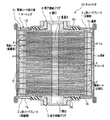
図1は、本発明の実施形態に係るレーザ溶接方法によって製造された電気シート組立体をケーシングに溶解液とともに収容して構成した電気二重層キャパシタ(以後、単にキャパシタと称す)の縦断面図である。
Hereinafter, embodiments of the present invention will be described in detail with reference to the drawings.
FIG. 1 is a longitudinal sectional view of an electric double layer capacitor (hereinafter simply referred to as a capacitor) configured by housing an electric sheet assembly manufactured by a laser welding method according to an embodiment of the present invention together with a solution in a casing. is there.
図1に示すように、キャパシタ10は、ケーシング1と、このケーシング1の内部に積層収容される複数枚の電極シート2と、積層された積層体LAを上下方向から挟み込むように該積層体LAを定形保持する2つのL形リードプレート3とで構成され、前記2つのL形リードプレート3で前記積層体LAを定形保持することで、電極シート組立体EAが構成されるようにしている。
そして、複数枚の電極シート2の積層方向におけるケーシング1の両端には電解液を注入するための開口6,7がそれぞれ設けられている。
また、前記2つのL形リードプレート3の後記する保持壁32には絶縁膜13が設けられている。
As shown in FIG. 1, a
And the opening 6 and 7 for inject | pouring electrolyte solution are provided in the both ends of the casing 1 in the lamination direction of the
An
≪ケーシング≫
ケーシング1は、適宜の高さで上下を開口させた角形筒状の筒部1aと、この筒部1aの上下の開口部にそれぞれ取付けられる上下の蓋部1b,1bとで構成され、前記筒部1a内に複数枚の電極シート2を積層収容せしめた後に、前記筒部1aの上下の開口縁部に蓋部1b,1bの周辺縁部が曲げ加工やカシメ加工、あるいは溶着(融着)などによって取付けることで、積層された電極シート2が電解液とともに密閉状に収容されるようにしている。
なお、前記筒部1aの高さは、絶縁性のセパレータ4を介して正極側と負極側とが交互に積層される電極シート2の積層枚数に相当する程度である。
そして、上下の蓋部1b,1bの中央部分には電解液を注入するための開口6,7が、後記の端子接続プラグ8,9によって備えられるようにしている。
≪Casing≫
The casing 1 is composed of a rectangular cylindrical tube portion 1a that is open at an appropriate height and upper and
The height of the cylindrical portion 1a is equivalent to the number of stacked
And the opening 6 and 7 for inject | pouring electrolyte solution is provided in the center part of the upper and
≪電極シート≫
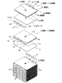
図2は、正極側と負極側の複数枚の電極シートを、セパレータと電極シートの一辺側のリード部間に介在されるシムとを介して交互に積層するその積層形態を示す斜視図である。図3は、積層形成された積層体を、2つのL形リードプレートによって上下から挟み込み保持する状態を示す斜視図である。
電極シート2は、正または負の電荷を貯めるため、略四角形状でかつシート状に形成された集電箔2aの一辺側の両面を除いたその両面全体に電極層2b,2bを備えることで形成され、前記一辺側を不図示の正極側の外部端子と負極側の外部端子にそれぞれのL形リードプレート3を介して電気的に導通させて前記各電極層2b,2bに貯めた電荷の取出し口としてのリード部2cとしている。
前記電極層2b,2bは、活性炭を主成分としており、前記集電箔2aの前記両面全体にわたって貼付けや塗布などにより略四角形状に形成されている。
≪Electrode sheet≫
FIG. 2 is a perspective view showing a lamination form in which a plurality of electrode sheets on the positive electrode side and the negative electrode side are alternately laminated via a separator and a shim interposed between lead portions on one side of the electrode sheet. . FIG. 3 is a perspective view showing a state in which the laminated body is sandwiched and held from above and below by two L-shaped lead plates.
In order to store positive or negative charges, the
The electrode layers 2b and 2b are mainly composed of activated carbon, and are formed in a substantially square shape by pasting or coating over the both surfaces of the
そして、前記電極層2b,2bを備える電極シート2の中央部分には、図2および図3に示すように、複数枚の電極シート2を積層せしめたときにその積層方向に貫通する貫通孔11を確保形成するための適宜孔径を有する通孔11aが設けられている。
また、図2に示すように、電極層2b,2bを備える集電箔2aの他辺側の両側コーナーをR状にカットすることによって、介在されるセパレータ4へのダメージを低減することができる。これにより、ショートを防ぎ、生産歩留りを向上させることができる。
And in the center part of the
Moreover, as shown in FIG. 2, the damage to the intervening separator 4 can be reduced by cutting the both-side corners on the other side of the
リード部2cは、図2に示すように、電極シート2の一辺側に、適宜の幅をもってその辺方向に沿って形成され、L形リードプレート3に超音波溶接など適宜の溶着手段によって電気的に溶着接続されるように形成されている。
また、リード部2cには図示のように、長孔12が2ヶ所に設けられており、これによって、材料削減による軽量化を図ると同時に、同じく積層介在されるシム5側に設けられている長孔14との積層連通によって、ガスの通り抜けをスムーズにしている。
As shown in FIG. 2, the
Further, as shown in the figure, the
前記正極側の電極シート2と負極側の電極シート2との間に介在されるセパレータ4の材質としては特に限定されるものではないが、電解液の保液率が高く、しかも、例えばN2などの乾燥流体をキャリアガスとして適宜に透過する適宜の絶縁部材であることが好ましい。その一例としてセルロース系が挙げられる。
このセパレータ4は、前記電極シート2の電極層2bに相当する大きさの略四角形状のシート状に形成され、積層隣り合う異極の電極シート2を絶縁する。
また、セパレータ4の中央部分には前記電極シート2に設けられている前記通孔11aとによって前記貫通孔11を確保形成するための略同じ程度の孔径を有する通孔11bが設けられている。
The material of the separator 4 interposed between the
The separator 4 is formed in a substantially rectangular sheet shape having a size corresponding to the
Further, a through
シム5は、導電性を有する略短冊状の部材であり、その角部が適宜R形状に面取りされるとともに、前記リード部2cの長孔12に対応した長孔14が適宜形成されている。
このシム5は、積層隣り合う前記電極シート2のリード部2cの間や、端に位置する前記電極シート2と前記L形リードプレート3との間に介在されるように配置されるようになっている。ここで、電極シート2と前記L形リードプレート3との間の距離は、同極の電極シート2のリード部2c間における距離に対して短いため、実際には、長さが異なる2種類のシム5がある。
The
The
≪L形リードプレート≫
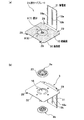
図4は、L形リードプレートを示す斜視図である。図5は、L形リードプレートに対する端子接続プラグの取付け構造を示す要部の拡大縦断面図である。
図4(a)に示すように、2つのL形リードプレート3は、積層された電極シート2群を、連結軸20による連結により定形保持する保持壁32と、前記電極シート2のリード部2cが電気的に導通するように溶着より接続される集電壁31とを備えている。
なお、本実施形態では、2つのL形リードプレート3の保持壁32に跨るように連結軸20を挿通させることで積層された電極シート2群を定形保持するようにしているため、連結軸20の材質を絶縁製にするか、あるいは一方の保持壁32に接する端部側部分を絶縁処理した金属製の連結軸20にすることによって、L形リードプレート3,3間の短絡を防止する必要がある。また、保持壁32,32から突出した連結軸20の端部処理としては、かしめやナット止めによる固定処理などが挙げられる。
≪L-shaped lead plate≫
FIG. 4 is a perspective view showing an L-shaped lead plate. FIG. 5 is an enlarged vertical cross-sectional view of the main part showing the structure for attaching the terminal connection plug to the L-shaped lead plate.
As shown in FIG. 4A, the two L-shaped
In the present embodiment, the connecting
保持壁32は、正極側と負極側の前記電極シート2を、そのリード部2cを相反する方向に向け、電極層2b同士を適合積層せしめた時の平面形状と略同じ形状を呈する四角形状に形成されている。
そして、図4(a)に示すように、集電壁31が折り曲げ連設される保持壁32の一辺側を除くその表面(内面)に絶縁膜13を貼り付けることによって、電極シート2の電極層2bが接する部分の絶縁処理を施している。ちなみに、この絶縁膜13は、テープ状やフィルム状を呈している。
このように、絶縁膜13を貼り付けて絶縁処理を施すことで、絶縁紙などの部品を削減することができ、その分、生産工数の削減とコストの削減が期待できる。
なお、図4(a)に示すように、絶縁膜13は前記保持壁32に取付けられる端子接続プラグ8,9の後記する雄側プラグ8bを覆うように備えられている。
The holding
And as shown to Fig.4 (a), by sticking the insulating
As described above, by applying the insulating treatment by attaching the insulating
As shown in FIG. 4A, the insulating
また、図4(b)および図5(a)示すように、保持壁32の中央部分には取付孔16が設けられており、前記端子接続プラグ8,9がシール性の高いOリング18をそれぞれ介在せしめた状態で前記取付孔16の開口縁を挟み込むように該取付孔16に取付けられるようにしている(図5(b)参照)。
4 (b) and 5 (a), a mounting
集電壁31は、図4に示すように、前記保持壁32,4bの一辺縁から同辺縁幅より狭い幅をもって一体に折り曲げ連設されると共に、その両辺縁部を縁方向に沿って内側(電極シート2側)に折り曲げることで、前記電極シート2のリード部2cを溶着により電気的に接続するための屈曲部19aとしている。
また、集電壁31の幅方向の略中央部分には前記屈曲部19aの曲げ方向で前記電極シート2の積層方向に延びるビード部19bが凸状に形成されている。
As shown in FIG. 4, the current collecting
Further, a
端子接続プラグ8は、電流の取出部であって、不図示の正極側と負極側の外部端子がねじ込み方式にて取付けられるものであり、図5(a)に示すように、雌側プラグ8aと雄側プラグ8bとで構成されている。
雌側プラグ8aは、一端外周に鍔部23を備えると共に、軸心開口部に雌ねじ24を備えている。雄側プラグ8bは、一端外周に鍔部25を備え、軸心に前記開口6,7を設けると共に、外周面に前記雌ねじ24に螺合連結せしめる雄ねじ26を備えている。
なお、端子接続プラグ9は、前記端子接続プラグ8と構成が基本的に同じことから、重複説明を省略し、また、図面中への符号をも省略する。
The
The female-
The
図2および図3において、連結孔27,28,29は、前記電極シート2のリード部2cと、前記シム5、そして前記L形リードプレート3の保持壁32にそれぞれ備えられており、複数枚の電極シート2を、図2に示すように、セパレータ4と電極シート2の一辺側のリード部2c間に介在されるシム5とを介して交互に積層せしめて積層体LAを形成する。
そして、図3に示す方向から積層体LAにL形リードプレート3をそれぞれセットさせた後に、前記連結孔27,28,29に亘って4本の前記連結軸20…をそれぞれ挿通させて前記積層体LAの積層形態を定形保持することで、電極シート組立体EAの製造が完了する。
2 and 3, the connecting
Then, after the L-shaped
≪電極シート組立体の製造≫
まず始めに、図2および図3に示すように、複数枚の正極側の電極シート2と負極側の電極シート2を、それぞれのリード部2cを相反する方向に向けた状態で、セパレータ4とシム5とをそれぞれ介在させながら交互に積層させることで、積層体LAが形成される。
そして、積層体LAに正極側と負極側のそれぞれのL形リードプレート3をセットすると共に、四隅コーナーにおいてそれぞれ積層方向に連通する前記連結孔27,28,29に亘って4本の前記連結軸20…をそれぞれ挿通させることで、積層体LAの積層形態が仮止めにて定形保持された電極シート組立体ELの製造が完了する。
≪Manufacture of electrode sheet assembly≫
First, as shown in FIG. 2 and FIG. 3, with the plurality of
The L-shaped
≪レーザ溶接方法≫
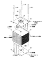
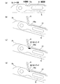
図6は、本発明のレーザ溶接方法による溶接領域を示す電極シート組立体の斜視図である。図7は、本発明のレーザ溶接方法による溶接領域におけるL形リードプレートの集電壁と電極シートの集電箔との溶接部を示す要部の拡大概略図である。
≪Laser welding method≫
FIG. 6 is a perspective view of an electrode sheet assembly showing a welding region by the laser welding method of the present invention. FIG. 7 is an enlarged schematic view of the main part showing the welded portion between the current collecting wall of the L-shaped lead plate and the current collector foil of the electrode sheet in the welding region by the laser welding method of the present invention.
図6に示すように、溶接領域Lは、L形リードプレート3の集電壁31の高さ(長さ)方向にほぼ全高にわたって存在する前記集電壁31の屈曲部19aと積層された各電極シート2のリード部2c、そしてシム5との間の隅肉Mであり、レーザ照射、例えばYAGビームによって前記各電極シート2と集電壁31の屈曲部19aおよび前記シム5間の隅肉Mを溶融してビードBを形成し、各電極シート2と集電壁31とを電気的に導通させるように接合する。
なお、図6に示す矢印Nは、電流の流れ方向を示している。
As shown in FIG. 6, each welding region L is laminated with the
In addition, the arrow N shown in FIG. 6 has shown the flow direction of an electric current.
本実施形態において、レーザ照射を行う場合、溶接領域L全長にわたって第1のレーザ照射を行うことで、前記溶接領域Lの予備加熱を行い。そして、加熱された前記溶接領域Lに第2のレーザ照射によってビードBを形成する本溶接を行うようにしている。
また、図6に示すように、前記L形リードプレート3の前記保持壁32に対する前記集電壁31の連設基部側を前記溶接領域Lにおける溶接起点P1とし、該溶接起点P1から前記集電壁31の高さ方向の略途中部位までを開始する溶接初期の範囲L1とし、そして、前記略途中部位から溶接終点P2となる前記集電壁31の開放端部側までを溶接後期の範囲L2として、レーザ照射を行うようにしている。
In this embodiment, when performing laser irradiation, the welding area L is preheated by performing the first laser irradiation over the entire length of the welding area L. And the main welding which forms the bead B by the 2nd laser irradiation to the said welding area | region L heated is performed.
Further, as shown in FIG. 6, the connecting base portion side of the current collecting
そして、本実施形態において、レーザ照射を行う場合、前記溶接初期の範囲L1は、レーザの送り速度を遅めに設定する一方で、前記溶接後期の範囲L2では、前記送り速度を前記溶接初期の範囲L1よりも速めに設定するなどのレーザの送り速度を徐変するレーザの送り速度を適宜制御することによって、図6および図7に示すように、送り速度が遅い前記溶接初期の範囲L1では巾の広いビードB1が形成され、送り速度が速い前記溶接後期の範囲L2では幅の狭いビードB2が形成されるようにしている(図6(b)および図7(c)、(d)参照)。
また、図7(b)に示すように、レーザ照射を行う際に、溶けた溶融液が、前記電極シート2のリード部2cと前記集電壁31の屈曲部19aとの間の隅肉Mに重力で流れ込むように、図7(a)に示す状態から前記重力方向に前記電極シート組立体ELを適宜傾斜させて行うようにしている。
In the present embodiment, when laser irradiation is performed, the welding initial range L1 is set so that the laser feed rate is set slower, while in the welding late range L2, the feed rate is set to the initial welding range. By appropriately controlling the laser feed rate that gradually changes the laser feed rate, such as setting it faster than the range L1, as shown in FIGS. 6 and 7, in the initial welding range L1 where the feed rate is slow, as shown in FIGS. A wide bead B1 is formed, and a narrow bead B2 is formed in the late welding range L2 where the feed rate is fast (see FIGS. 6B, 7C, and 7D). ).
Further, as shown in FIG. 7B, when laser irradiation is performed, the melted melt is a fillet M between the
しかして、本実施形態におけるレーザ溶接方法によれば、まず始めに、図7(b)に矢印Xにて示す照射角度で前記電極シート2のリード部2cと前記集電壁31の屈曲部19aとの間の隅肉Mを第1のレーザ照射によって加熱し、前記溶接領域Lの範囲における隅肉Mを予熱する。このとき、第2のレーザ照射によって前記隅肉Mを溶かしてビードBを形成する本溶接に備えて、図7(a)に示す水平状態から図7(b)に示す傾斜状態まで前記電極シート組立体ELを適宜傾斜させておくもよい。
Thus, according to the laser welding method of the present embodiment, first, the
第1のレーザ照射により前記溶接領域Lの範囲における前記隅肉Mを加熱した後に、第2のレーザ照射による本溶接を行う。このとき、前記電極シート組立体ELを図7(a)に示す水平状態から図7(b)に示す傾斜状態まで適宜傾斜させるとともに、図6(a)に示す溶接領域Lの範囲において、溶接初期の範囲L1におけるレーザの送り速度よりも溶接後期の範囲L2における前記送り速度を速く設定する。
このようにして、第2のレーザ照射による溶接を行うことで、前記リード部2cと前記屈曲部19aとの間の隅肉Mは第1の溶接により加熱された入熱量によって確実に溶け、溶けた溶融液は、前記隅肉M間に重力で流れ込む。そして、レーザの送り速度の徐変制御によって、前記溶接初期の範囲L1に幅の広いビードB1が形成され、溶接後期の範囲L2には巾が狭いビードB2が形成される(図6(b)および図7(c)、(d)参照)。
After the fillet M in the range of the welding region L is heated by the first laser irradiation, the main welding by the second laser irradiation is performed. At this time, the electrode sheet assembly EL is appropriately inclined from the horizontal state shown in FIG. 7A to the inclined state shown in FIG. 7B, and welding is performed in the range of the welding region L shown in FIG. The feed rate in the latter range L2 is set faster than the laser feed rate in the initial range L1.
In this way, by performing the welding by the second laser irradiation, the fillet M between the
本実施形態によれば、電極シート2のリード部2cとL形リードプレート3の集電壁31との隅肉M間(溶接領域L)の入熱量を増やして確実に溶融させ、前記溶接初期の範囲L1によって入熱されている前記隅肉M間の入熱と放熱とのバランスをとるように溶接後期の範囲L2ではレーザの送り速度を速めるなどの送り速度の徐変制御を行うことで、生産時間の短縮を図りながら、均一で良好なビードを前記隅肉M間に安定よく形成することができる。
According to the present embodiment, the amount of heat input between the fillet M (welding region L) between the
以上、本発明の実施の形態を図面により説明したが、本発明の具体的な構成はこの実施の形態に限られるものではなく、請求項1〜請求項5に記載の本発明の要旨を逸脱しない範囲の設計において変更などがあっても本発明に含まれるものである。 As mentioned above, although embodiment of this invention was described with drawing, the concrete structure of this invention is not restricted to this embodiment, It deviates from the summary of this invention of Claims 1-5 Even if there is a change in the design of the range not to be included, it is included in the present invention.
1 ケーシング
1a 筒部
1b 蓋部
2 電極シート
2a 集電箔
2b 電極層
2c リード部
3 L形リードプレート
31 集電壁
32 保持壁
4 セパレータ
5 シム
8,9 端子接続プラグ
10 キャパシタ
B,B1,B2 ビード
L 溶接領域
L1 溶接初期の範囲
L2 溶接後期の範囲
P1 溶接起点
P2 溶接終点
EL 電極シート組立体
LA 積層体
DESCRIPTION OF SYMBOLS 1 Casing
Claims (5)
被溶接部材の溶接領域を第1のレーザ照射によって加熱した後に、加熱された前記溶接領域に第2のレーザ照射による溶接を行うことを特徴とする電気化学素子における溶接領域のレーザ溶接方法。 A laser welding method of a welding region in an electrochemical element,
A method for laser welding a welding region in an electrochemical element, comprising: heating a welding region of a member to be welded by first laser irradiation, and performing welding by second laser irradiation on the heated welding region.
前記集電箔上に設けた電極層と、を備え、
前記電極層の間に電解液を含有させるセパレータを介して複数枚が交互に積層される電極シートにおいて、
前記複数枚の電極シートと前記セパレータとを交互に積層させてなる積層体を、2つのL形リードプレートを用いて定形保持せしめた後に、前記集電箔を前記2つのL形リードプレートに溶接によってそれぞれ電気的に接合導通せしめることによって形成される電極シート組立体を、前記電解液とともに密閉されたケーシングに収容している電気化学素子における溶接領域のレーザ溶接方法であって、
前記2つのL形リードプレートは、前記積層された電極シートの各集電箔に溶接により電気的に導通させる集電壁と、
前記集電壁から一体に折り曲げ連設されると共に、電流の取出部を備える保持壁と、備え、
前記集電箔と前記集電壁の幅方向両辺端部との溶接領域をレーザ照射により隅肉溶接する際に、前記集電箔と前記集電壁との溶けた溶融液が、該集電箔と集電壁との間に重力で流れ込むように、その重力方向に前記電極シート組立体を適宜傾斜させて行うことを特徴とする電気化学素子における溶接領域のレーザ溶接方法。 Current collector foil,
An electrode layer provided on the current collector foil,
In the electrode sheet in which a plurality of sheets are alternately laminated via a separator containing an electrolytic solution between the electrode layers,
A laminate formed by alternately laminating the plurality of electrode sheets and the separator is held in a fixed shape by using two L-shaped lead plates, and then the current collector foil is welded to the two L-shaped lead plates. A welding region laser welding method in an electrochemical element in which an electrode sheet assembly formed by electrically connecting and conducting each is housed in a sealed casing together with the electrolyte,
The two L-shaped lead plates are current collecting walls electrically connected to the current collecting foils of the laminated electrode sheets by welding,
A bent wall that is integrally bent from the current collecting wall, and a holding wall that includes a current extraction portion; and
When the fillet weld is performed by laser irradiation on the welding region between the current collector foil and the widthwise side edges of the current collector wall, the melted solution of the current collector foil and the current collector wall is the current collector. A laser welding method for a welding region in an electrochemical element, wherein the electrode sheet assembly is appropriately inclined in the direction of gravity so as to flow between the foil and the current collecting wall by gravity.
The continuous base side of the current collecting wall with respect to the holding wall of the L-shaped lead plate is used as a welding starting point in the welding region, and the range from the welding starting point to a substantially halfway portion in the height direction of the current collecting wall is within the initial range of the welding. 5. The laser in the welding region of the electrochemical element according to claim 2, wherein the range from the substantially midway portion to the open end portion side of the current collecting wall that is a welding end point is a range of the latter stage of welding. Welding method.
Priority Applications (1)
| Application Number | Priority Date | Filing Date | Title |
|---|---|---|---|
| JP2005144098A JP2006324323A (en) | 2005-05-17 | 2005-05-17 | Laser welding method of welding region in electrochemical element |
Applications Claiming Priority (1)
| Application Number | Priority Date | Filing Date | Title |
|---|---|---|---|
| JP2005144098A JP2006324323A (en) | 2005-05-17 | 2005-05-17 | Laser welding method of welding region in electrochemical element |
Publications (1)
| Publication Number | Publication Date |
|---|---|
| JP2006324323A true JP2006324323A (en) | 2006-11-30 |
Family
ID=37543800
Family Applications (1)
| Application Number | Title | Priority Date | Filing Date |
|---|---|---|---|
| JP2005144098A Withdrawn JP2006324323A (en) | 2005-05-17 | 2005-05-17 | Laser welding method of welding region in electrochemical element |
Country Status (1)
| Country | Link |
|---|---|
| JP (1) | JP2006324323A (en) |
Cited By (2)
| Publication number | Priority date | Publication date | Assignee | Title |
|---|---|---|---|---|
| CN111512491A (en) * | 2018-01-02 | 2020-08-07 | 三星Sdi株式会社 | Battery pack and method of making the same |
| US20250205808A1 (en) * | 2022-03-16 | 2025-06-26 | Panasonic Intellectual Property Management Co., Ltd. | Manufacturing apparatus |
-
2005
- 2005-05-17 JP JP2005144098A patent/JP2006324323A/en not_active Withdrawn
Cited By (4)
| Publication number | Priority date | Publication date | Assignee | Title |
|---|---|---|---|---|
| CN111512491A (en) * | 2018-01-02 | 2020-08-07 | 三星Sdi株式会社 | Battery pack and method of making the same |
| US11670803B2 (en) | 2018-01-02 | 2023-06-06 | Samsung Sdi Co., Ltd. | Battery pack and manufacturing method therefor |
| CN111512491B (en) * | 2018-01-02 | 2023-09-12 | 三星Sdi株式会社 | Battery pack and manufacturing method |
| US20250205808A1 (en) * | 2022-03-16 | 2025-06-26 | Panasonic Intellectual Property Management Co., Ltd. | Manufacturing apparatus |
Similar Documents
| Publication | Publication Date | Title |
|---|---|---|
| CN101911342B (en) | Battery cell design with asymmetrical terminals | |
| CN101997136B (en) | Secondary cell and its manufacture method | |
| JP5175265B2 (en) | Lithium secondary battery with improved safety and capacity | |
| KR101269939B1 (en) | Secondary Battery having a Convex Structure | |
| KR100813813B1 (en) | Secondary Battery of Improved Safety | |
| CN102473529B (en) | Electrochemical device | |
| CN107039682A (en) | Secondary cell | |
| WO2004084244A1 (en) | Multilayer capacitor and method for manufacturing multilayer capacitor | |
| CN103534838A (en) | Negative electrode terminal for battery and method for producing negative electrode terminal for battery | |
| KR20100135382A (en) | Lithium Secondary Battery with Multi-Directional Lead-Tab Structure | |
| JP2016012542A (en) | Power storage device | |
| JP5354056B2 (en) | Power storage device | |
| KR102774838B1 (en) | Terminal component, secondary battery, and battery pack | |
| KR20170104826A (en) | Electrode assembly and secondary battery comprising the same | |
| JP3686242B2 (en) | Battery stack electrode connection method and battery | |
| KR20190101372A (en) | Battery cell and method of manufacturing the battery cell | |
| CN111987280A (en) | Battery pack | |
| JP4513125B2 (en) | Electrochemical device and manufacturing method thereof | |
| CN114843670A (en) | Electrode terminal and use thereof | |
| JP2007207920A (en) | Capacitor | |
| JP5229440B2 (en) | Electrochemical devices | |
| KR20130122564A (en) | Pouch-typed secondary battery having improved safety by preventing internal moving of electrode assembly | |
| CN219371278U (en) | Battery device | |
| JP2006324323A (en) | Laser welding method of welding region in electrochemical element | |
| CN101946345A (en) | Method for producing an individual cell for a battery |
Legal Events
| Date | Code | Title | Description |
|---|---|---|---|
| A300 | Application deemed to be withdrawn because no request for examination was validly filed |
Free format text: JAPANESE INTERMEDIATE CODE: A300 Effective date: 20080805 |