EP4495557A2 - System zur identifizierung des standorts einer ausrüstung, abdeckung und verfahren zur identifizierung des standorts einer ausrüstung - Google Patents
System zur identifizierung des standorts einer ausrüstung, abdeckung und verfahren zur identifizierung des standorts einer ausrüstung Download PDFInfo
- Publication number
- EP4495557A2 EP4495557A2 EP24217005.8A EP24217005A EP4495557A2 EP 4495557 A2 EP4495557 A2 EP 4495557A2 EP 24217005 A EP24217005 A EP 24217005A EP 4495557 A2 EP4495557 A2 EP 4495557A2
- Authority
- EP
- European Patent Office
- Prior art keywords
- overhead cable
- vibration
- optical fiber
- cover
- optical
- Prior art date
- Legal status (The legal status is an assumption and is not a legal conclusion. Google has not performed a legal analysis and makes no representation as to the accuracy of the status listed.)
- Pending
Links
Images


Classifications
-
- G—PHYSICS
- G01—MEASURING; TESTING
- G01H—MEASUREMENT OF MECHANICAL VIBRATIONS OR ULTRASONIC, SONIC OR INFRASONIC WAVES
- G01H9/00—Measuring mechanical vibrations or ultrasonic, sonic or infrasonic waves by using radiation-sensitive means, e.g. optical means
- G01H9/004—Measuring mechanical vibrations or ultrasonic, sonic or infrasonic waves by using radiation-sensitive means, e.g. optical means using fibre optic sensors
-
- G—PHYSICS
- G01—MEASURING; TESTING
- G01B—MEASURING LENGTH, THICKNESS OR SIMILAR LINEAR DIMENSIONS; MEASURING ANGLES; MEASURING AREAS; MEASURING IRREGULARITIES OF SURFACES OR CONTOURS
- G01B11/00—Measuring arrangements characterised by the use of optical techniques
-
- G—PHYSICS
- G01—MEASURING; TESTING
- G01B—MEASURING LENGTH, THICKNESS OR SIMILAR LINEAR DIMENSIONS; MEASURING ANGLES; MEASURING AREAS; MEASURING IRREGULARITIES OF SURFACES OR CONTOURS
- G01B11/00—Measuring arrangements characterised by the use of optical techniques
- G01B11/002—Measuring arrangements characterised by the use of optical techniques for measuring two or more coordinates
Definitions
- the present disclosure relates to a technique for specifying a route of an overhead cable including optical fibers by expressing the route with the length of optical fibers from a communication-intensive building.
- a technique for specifying a position of a facility using an optical fiber vibration sensor is known (for example, see PTL 1 and PTL 2).
- a hit vibration can be measured and the position on the optical fiber 25, in the longitudinal direction, from the communication-intensive building 10 (a distance from the communication-intensive building 10 to the position where vibration is applied) can be specified.
- a communication optical fiber 35 exists in underground 6 at the position and to collate the manhole position with a fiber route map, without opening the manhole 30.
- an object of the present invention is to provide a facility position specification system, a cover, and a facility position specification method capable of specifying a route of an overhead cable without directly disturbing the overhead cable itself.
- An object of the present invention is to provide a facility position specification system, a cover, and a facility position specification method capable of specifying a route of an overhead cable without directly giving disturbance to the overhead cable itself.
- a facility position specification system is a facility position specification system for specifying a position of an overhead cable, the system including
- the facility position specifying method according to the present invention is a facility position specifying method for specifying a position of an overhead cable, the method including
- a cover is attached to an arbitrary position on the overhead cable, and vibration is applied to the overhead cable through the cover. Since, in the facility position specification system (method), the overhead cable is not hit directly, optical fiber vibration sensing can be performed in a state where the likelihood of affecting communication is small.
- the facility position specifying method according to the present invention is a facility position specifying method for specifying a position of a pillar supporting an overhead cable, the method including connecting an optical measuring instrument to an end portion of an optical fiber included in the overhead cable,
- the present invention can provide a facility position specification system, and a facility position specification method capable of specifying a route of an overhead cable without directly giving disturbance to the overhead cable itself.
- the cover of the facility position specification system may include a vibration mechanism for applying the vibration. That is, the cover includes a vibration mechanism for generating vibration and a cylinder for covering an overhead cable including an optical cable at an arbitrary position and transmitting the vibration to the overhead cable. It is not necessary for a worker to directly hit, and remote control is possible.
- the cover of the facility position specification system may have a fold on an inner wall thereof, which is in contact with the overhead cable and transmits the vibration to the overhead cable. That is, the cover includes a cylinder for covering an overhead cable including an optical cable at an arbitrary position and a fold disposed on an inner wall of the cylinder, coming into contact with the overhead cable, and transmitting vibration of the cylinder to the overhead cable. The vibration from the cover can be efficiently transmitted to the overhead cable.
- the present invention can provide a facility position specification system, a cover, and a facility position specification method capable of specifying a route of an overhead cable without directly giving disturbance to the overhead cable itself.
- a facility position specification system for specifying a position of an overhead cable.
- the facility position specification system comprises:
- the cover includes a vibration mechanism for applying the vibration.
- the cover has a fold on an inner wall thereof, the fold being in contact with the overhead cable and transmitting the vibration to the overhead cable.
- a cover comprising a vibration mechanism for generating vibration; and a cylinder for covering an overhead cable including an optical cable at an arbitrary position and transmitting the vibration to the overhead cable.
- a cover comprising a cylinder for covering an overhead cable including an optical cable at an arbitrary position; and a fold disposed on an inner wall of the cylinder, coming into contact with the overhead cable, and transmitting vibration of the cylinder to the overhead cable.
- a facility position specifying method for specifying a position of an overhead cable comprising:
- a facility position specifying method for specifying a position of a pillar supporting an overhead cable comprising:
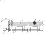
- Fig. 2 is a diagram illustrating a facility position specification system according to the present invention.
- the facility position specification system is a facility position specification system for specifying a position of an overhead cable 26, the system including
- the overhead cable 26 is a cable stretched in the air by a pillar or the like.
- the overhead cable 26 is a metal wire or an optical fiber cable for power supply.
- the optical fiber 25 used in this system is laid along the overhead cable 26.
- the optical fiber in the optical fiber cable can be used as the optical fiber 25.
- the cover 40 is disposed so as to cover the overhead cable 26.
- the cover 40 may be attached when laying the overhead cable 26, or the cover 40 may be attached to the overhead cable 26 by a worker every inspection.
- the cover 40 has a function of transmitting vibration such as a given hit to the overhead cable 26.
- the cover 40 is preferably made of a material having a high modulus of elasticity (a high Young's modulus) and a low density, for example, a metal, in order to efficiently transmit vibration to the cable.
- Fig. 3 is a diagram illustrating a structure of the cover 40.
- the cover 40 includes
- the cover 40 covers the overhead cable 26 with the cylinder 41.
- the cylinder 41 and the overhead cable 26 are not in direct contact with each other.
- the cover 40 has a fold 42, and a space is generated between the cylinder 41 and the overhead cable 26 by the fold 42 coming into contact with the overhead cable 26.
- the vibration from the cylinder 41 is transmitted to the overhead cable 26 through the folds 42.
- the vibration from the cylinder 41 can be efficiently transmitted to the overhead cable 26.
- the number of folds 42 and the length L of the cover 40 may be adjusted.
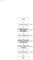
- Fig. 4 is a flowchart illustrating the facility position specifying method.
- the present facility position specifying method includes
- step S01 the cover 40 is attached to the overhead cable 26 whose position is desired to be ascertained.
- the number of covers 40 is arbitrary.
- the cover 40 may be attached when laying the overhead cable 26, or the cover 40 may be attached to the overhead cable 26 by a worker every inspection.
- step S02 One end of the overhead cable 26 is drawn into a communication-intensive building 10.
- the optical fiber 25 is taken out from the overhead cable 26 drawn into the communication-intensive building 10, and is connected to the optical measuring instrument 20 (the end of the optical fiber 25 connected to the optical measuring instrument 20 is defined as "one end”).
- the optical measuring instrument 20 is, for example, an optical time domain reflectometer (OTDR).
- step S03 test light is input from the optical measuring instrument 20 to one end of the optical fiber 25, and the vibration is applied to the cover 40 during an optical test in which back scattered light output from the one end of the optical fiber 25 is measured by the optical measuring instrument 20.
- the vibration applying method will be described.
- an operator applies a hit 15 to the cover by a hammer or the like.
- the operator may hit the cover by a long bar type hammer reaching from the ground. Further, the operator may move to the vicinity of the cover 40 by a bucket truck and hit the cover by a hammer.
- the cover 40 includes a vibration mechanism 43 for generating vibration in the cylinder 41.
- the vibration mechanism 43 is disposed in the cylinder 41, for example, and is composed of a piezoelectric moving by radio waves and a battery such as a solar cell for supplying electric power to the piezoelectric.
- a worker can apply vibration remotely without riding on a bucket truck or the like.
- Fig. 7 is a table in which the work styles in the step S03 are summarized.
- the cover 40 is always attached to the overhead cable 26 and where the cover 40 is always attached to the overhead cable 26 at the time of inspection.
- the vibration applying method is used for hitting the cover 40 with a hammer or the like, the cover 40 does not require a vibration mechanism, but it is necessary to dispatch the worker to the work site.
- the optical measuring instrument 20 acquires an optical intensity distribution of back scattered light output from one end of an optical fiber 25.
- Fig. 8 shows an example of an optical intensity distribution obtained by the optical measuring instrument 20.
- the horizontal axis represents the distance from one end of the optical fiber 25.
- the vertical axis represents the light intensity of the back scattered light. It can be seen that there is a waveform peak at the position of the distance z and vibration was applied at this position.
- a signal processing unit 21 matches a map 50 showing the layout of the overhead cable 26 with the optical intensity distribution of Fig. 8 .
- Fig. 9 is a diagram illustrating matching work. On which route the overhead cable is laid when the overhead cable 26 is laid is recorded in the map 50.
- the signal processing unit 21 can determine which place the peak position (hit position 52) of the optical intensity distribution illustrated in Fig. 8 corresponds to on the map 50.
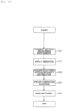
- Fig. 10 is a flowchart for illustrating a facility position specifying method according to the present embodiment.
- Fig. 11 is a diagram for illustrating a facility position specification system to be inspected by the present facility position specifying method.
- the present facility position specifying method is a method for specifying a facility position without attaching the cover 40 in comparison with the facility position specifying method of Embodiment 1.
- the present facility position specification method includes connecting the optical measuring instrument 20 to an end portion of the optical fiber 25 included in the overhead cable 26 (step S02),
- the pillar 35 supporting the overhead cable 26 is hit instead of hitting the cover.
- the vibration is transmitted to the optical fiber 25 of the overhead cable 26, and the scattered optical intensity distribution as illustrated in Fig. 8 can be acquired by the optical measuring instrument 20. Therefore, as illustrated with reference to Fig. 9 , by collating the scattered optical intensity distribution with the map 50 in which the laying of the overhead cable 26 is described, it is possible to specify the actual position of the pillar 35 (the position on the map).
- the present facility position specifying method does not require the work of attaching the cover to the overhead cable 26 in comparison with the facility position specifying method described in Embodiment 1, and can simply ascertain the standard of the position of the overhead cable 26 and the position of the electric pillar.
- the vibration is applied to the cover or the pillar attached to the overhead cable and vibration is applied to the overhead cable without directly applying hit to the overhead cable, the scattered optical intensity distribution can be acquired without damaging the overhead cable.
- the position and existence of the overhead cable and the electric pillar can be determined at the site where the worker is dispatched, and further, the overhead cable and the electric pillar can be matched with a map.
- the position and existence of the overhead cable can be determined even in a place where no electric pillar exists, and the overhead cable can be matched with the map.
- the vibration can be applied to the overhead cable remotely.
Landscapes
- Physics & Mathematics (AREA)
- General Physics & Mathematics (AREA)
- Length Measuring Devices By Optical Means (AREA)
Priority Applications (1)
| Application Number | Priority Date | Filing Date | Title |
|---|---|---|---|
| EP24217005.8A EP4495557A3 (de) | 2021-01-21 | 2021-01-21 | System zur identifizierung des standorts einer ausrüstung, abdeckung und verfahren zur identifizierung des standorts einer ausrüstung |
Applications Claiming Priority (3)
| Application Number | Priority Date | Filing Date | Title |
|---|---|---|---|
| EP21920990.5A EP4283250A4 (de) | 2021-01-21 | 2021-01-21 | System zur bestimmung des standortes einer anlage, abdeckung und verfahren zur bestimmung des standortes einer anlage |
| PCT/JP2021/002003 WO2022157877A1 (ja) | 2021-01-21 | 2021-01-21 | 設備位置特定システム、カバー、及び設備位置特定方法 |
| EP24217005.8A EP4495557A3 (de) | 2021-01-21 | 2021-01-21 | System zur identifizierung des standorts einer ausrüstung, abdeckung und verfahren zur identifizierung des standorts einer ausrüstung |
Related Parent Applications (1)
| Application Number | Title | Priority Date | Filing Date |
|---|---|---|---|
| EP21920990.5A Division EP4283250A4 (de) | 2021-01-21 | 2021-01-21 | System zur bestimmung des standortes einer anlage, abdeckung und verfahren zur bestimmung des standortes einer anlage |
Publications (2)
| Publication Number | Publication Date |
|---|---|
| EP4495557A2 true EP4495557A2 (de) | 2025-01-22 |
| EP4495557A3 EP4495557A3 (de) | 2025-04-02 |
Family
ID=82548548
Family Applications (3)
| Application Number | Title | Priority Date | Filing Date |
|---|---|---|---|
| EP24217005.8A Pending EP4495557A3 (de) | 2021-01-21 | 2021-01-21 | System zur identifizierung des standorts einer ausrüstung, abdeckung und verfahren zur identifizierung des standorts einer ausrüstung |
| EP24217041.3A Pending EP4495558A3 (de) | 2021-01-21 | 2021-01-21 | System zur identifizierung des standorts einer ausrüstung, abdeckung und verfahren zur identifizierung des standorts einer ausrüstung |
| EP21920990.5A Pending EP4283250A4 (de) | 2021-01-21 | 2021-01-21 | System zur bestimmung des standortes einer anlage, abdeckung und verfahren zur bestimmung des standortes einer anlage |
Family Applications After (2)
| Application Number | Title | Priority Date | Filing Date |
|---|---|---|---|
| EP24217041.3A Pending EP4495558A3 (de) | 2021-01-21 | 2021-01-21 | System zur identifizierung des standorts einer ausrüstung, abdeckung und verfahren zur identifizierung des standorts einer ausrüstung |
| EP21920990.5A Pending EP4283250A4 (de) | 2021-01-21 | 2021-01-21 | System zur bestimmung des standortes einer anlage, abdeckung und verfahren zur bestimmung des standortes einer anlage |
Country Status (5)
| Country | Link |
|---|---|
| US (1) | US20240060817A1 (de) |
| EP (3) | EP4495557A3 (de) |
| JP (1) | JPWO2022157877A1 (de) |
| CN (1) | CN116569002A (de) |
| WO (1) | WO2022157877A1 (de) |
Families Citing this family (3)
| Publication number | Priority date | Publication date | Assignee | Title |
|---|---|---|---|---|
| US20220333956A1 (en) * | 2021-04-14 | 2022-10-20 | Nec Laboratories America, Inc | Mapping using optical fiber sensing |
| JPWO2024166295A1 (de) * | 2023-02-09 | 2024-08-15 | ||
| WO2026022889A1 (ja) * | 2024-07-22 | 2026-01-29 | Ntt株式会社 | 光線路設備位置特定方法 |
Citations (2)
| Publication number | Priority date | Publication date | Assignee | Title |
|---|---|---|---|---|
| JP2020052030A (ja) | 2018-09-20 | 2020-04-02 | 日本電信電話株式会社 | マンホール位置特定方法及びマンホール位置特定システム |
| JP2020127094A (ja) | 2019-02-01 | 2020-08-20 | 日本電信電話株式会社 | 光ファイバルート探索方法、光ファイバルート探索装置及びプログラム |
Family Cites Families (9)
| Publication number | Priority date | Publication date | Assignee | Title |
|---|---|---|---|---|
| JP3386966B2 (ja) * | 1996-12-17 | 2003-03-17 | 中部電力株式会社 | 架空送電線の事故検出位置標定システム |
| JP3914050B2 (ja) * | 2001-12-28 | 2007-05-16 | 日本特殊陶業株式会社 | ランジュバン型超音波振動子 |
| JP2010074938A (ja) * | 2008-09-18 | 2010-04-02 | Nippon Telegr & Teleph Corp <Ntt> | ケーブル探索方法及びケーブル探索装置 |
| JP5128519B2 (ja) * | 2009-02-24 | 2013-01-23 | 日本電信電話株式会社 | 光設備識別方法及び装置 |
| JP6723540B2 (ja) * | 2016-06-06 | 2020-07-15 | 西松建設株式会社 | 加振装置、振動測定システム、振動測定方法および張力の計測方法 |
| JP7124875B2 (ja) * | 2018-08-30 | 2022-08-24 | 日本電気株式会社 | 電柱位置特定システム、電柱位置特定装置、電柱位置特定方法、及びプログラム |
| JP7211134B2 (ja) * | 2019-02-12 | 2023-01-24 | 日本電信電話株式会社 | 架空光ファイバケーブル検査方法、架空光ファイバケーブル検査装置及びプログラム |
| WO2022044319A1 (ja) * | 2020-08-31 | 2022-03-03 | 日本電気株式会社 | 劣化判別システム、劣化判別装置、及び劣化判別方法 |
| JP7444289B2 (ja) * | 2020-11-27 | 2024-03-06 | 日本電気株式会社 | 位置特定システム、振動発生器、及び位置特定方法 |
-
2021
- 2021-01-21 WO PCT/JP2021/002003 patent/WO2022157877A1/ja not_active Ceased
- 2021-01-21 EP EP24217005.8A patent/EP4495557A3/de active Pending
- 2021-01-21 EP EP24217041.3A patent/EP4495558A3/de active Pending
- 2021-01-21 CN CN202180081160.1A patent/CN116569002A/zh active Pending
- 2021-01-21 US US18/269,858 patent/US20240060817A1/en not_active Abandoned
- 2021-01-21 JP JP2022576290A patent/JPWO2022157877A1/ja active Pending
- 2021-01-21 EP EP21920990.5A patent/EP4283250A4/de active Pending
Patent Citations (2)
| Publication number | Priority date | Publication date | Assignee | Title |
|---|---|---|---|---|
| JP2020052030A (ja) | 2018-09-20 | 2020-04-02 | 日本電信電話株式会社 | マンホール位置特定方法及びマンホール位置特定システム |
| JP2020127094A (ja) | 2019-02-01 | 2020-08-20 | 日本電信電話株式会社 | 光ファイバルート探索方法、光ファイバルート探索装置及びプログラム |
Also Published As
| Publication number | Publication date |
|---|---|
| EP4283250A4 (de) | 2025-01-01 |
| EP4495558A2 (de) | 2025-01-22 |
| US20240060817A1 (en) | 2024-02-22 |
| CN116569002A (zh) | 2023-08-08 |
| EP4495558A3 (de) | 2025-04-16 |
| WO2022157877A1 (ja) | 2022-07-28 |
| JPWO2022157877A1 (de) | 2022-07-28 |
| EP4283250A1 (de) | 2023-11-29 |
| EP4495557A3 (de) | 2025-04-02 |
Similar Documents
| Publication | Publication Date | Title |
|---|---|---|
| EP4495557A2 (de) | System zur identifizierung des standorts einer ausrüstung, abdeckung und verfahren zur identifizierung des standorts einer ausrüstung | |
| US11112332B2 (en) | Optical fiber monitoring method, and optical fiber monitoring system | |
| US11366231B2 (en) | Smart optical cable positioning/location using optical fiber sensing | |
| US11644347B2 (en) | Manhole position specification method and manhole position specification system | |
| JP2020519798A (ja) | トンネル用プレキャストセグメントならびにそのようなプレキャストセグメントを作製および監視する方法 | |
| JP2002366616A (ja) | マンホール情報の管理方法及び管理システム | |
| WO1993003400A1 (en) | Method of probing optical transmission line | |
| CN110361626B (zh) | 用于精确定位埋地电缆的电缆故障的方法 | |
| JP3386966B2 (ja) | 架空送電線の事故検出位置標定システム | |
| US8095003B2 (en) | Fiber optic testing system and method incorporating geolocation information | |
| JPH0611534A (ja) | 部分放電測定法 | |
| Warren et al. | Geosynthetic strain gage installation procedures and alternative strain measurement methods for roadway applications | |
| KR101551341B1 (ko) | 케이블 확인 장치 | |
| CN111679313A (zh) | 机械周期性震动激励确认电力光缆路由方法 | |
| KR102102187B1 (ko) | 데이터로거를 이용한 낙석계측시스템 | |
| KR20120138366A (ko) | 이도자동산출장치 | |
| EP2286265A2 (de) | Datenübertragungssystem mit ortungs-, identifikations- und messfunktion sowie ein verfahren hierzu | |
| Dubaniewicz et al. | Distributed measurement of conductor temperatures in mine trailing cables using fiber-optic technology | |
| JP5904955B2 (ja) | 携帯用端末装置およびその装置を用いた不可視物設備の位置特定方法 | |
| CN104749444A (zh) | 一种接地电阻测量装置 | |
| JP2001194191A (ja) | 土木構造物の変位計測方法および装置 | |
| KR101953022B1 (ko) | 하수관로 탐사용 손드부 | |
| KR20230064272A (ko) | 방진 및 방수 성능이 향상된 무선센서 장치 | |
| CN216873204U (zh) | 一种便携式光缆断点定位装置 | |
| JPH0443935A (ja) | 光ファイバケーブルの布設長測定方法 |
Legal Events
| Date | Code | Title | Description |
|---|---|---|---|
| PUAI | Public reference made under article 153(3) epc to a published international application that has entered the european phase |
Free format text: ORIGINAL CODE: 0009012 |
|
| STAA | Information on the status of an ep patent application or granted ep patent |
Free format text: STATUS: THE APPLICATION HAS BEEN PUBLISHED |
|
| AC | Divisional application: reference to earlier application |
Ref document number: 4283250 Country of ref document: EP Kind code of ref document: P |
|
| AK | Designated contracting states |
Kind code of ref document: A2 Designated state(s): AL AT BE BG CH CY CZ DE DK EE ES FI FR GB GR HR HU IE IS IT LI LT LU LV MC MK MT NL NO PL PT RO RS SE SI SK SM TR |
|
| REG | Reference to a national code |
Ref country code: DE Ref legal event code: R079 Free format text: PREVIOUS MAIN CLASS: G01H0009000000 Ipc: G01B0011000000 |
|
| PUAL | Search report despatched |
Free format text: ORIGINAL CODE: 0009013 |
|
| AK | Designated contracting states |
Kind code of ref document: A3 Designated state(s): AL AT BE BG CH CY CZ DE DK EE ES FI FR GB GR HR HU IE IS IT LI LT LU LV MC MK MT NL NO PL PT RO RS SE SI SK SM TR |
|
| RIC1 | Information provided on ipc code assigned before grant |
Ipc: G01H 9/00 20060101ALI20250224BHEP Ipc: G01B 11/00 20060101AFI20250224BHEP |
|
| STAA | Information on the status of an ep patent application or granted ep patent |
Free format text: STATUS: REQUEST FOR EXAMINATION WAS MADE |
|
| 17P | Request for examination filed |
Effective date: 20250416 |
|
| STAA | Information on the status of an ep patent application or granted ep patent |
Free format text: STATUS: EXAMINATION IS IN PROGRESS |
|
| 17Q | First examination report despatched |
Effective date: 20250612 |
|
| RAP3 | Party data changed (applicant data changed or rights of an application transferred) |
Owner name: NTT, INC. |
|
| GRAP | Despatch of communication of intention to grant a patent |
Free format text: ORIGINAL CODE: EPIDOSNIGR1 |
|
| STAA | Information on the status of an ep patent application or granted ep patent |
Free format text: STATUS: GRANT OF PATENT IS INTENDED |