EP4495557A2 - Equipment location identification system, cover, and equipment location identification method - Google Patents
Equipment location identification system, cover, and equipment location identification method Download PDFInfo
- Publication number
- EP4495557A2 EP4495557A2 EP24217005.8A EP24217005A EP4495557A2 EP 4495557 A2 EP4495557 A2 EP 4495557A2 EP 24217005 A EP24217005 A EP 24217005A EP 4495557 A2 EP4495557 A2 EP 4495557A2
- Authority
- EP
- European Patent Office
- Prior art keywords
- overhead cable
- vibration
- optical fiber
- cover
- optical
- Prior art date
- Legal status (The legal status is an assumption and is not a legal conclusion. Google has not performed a legal analysis and makes no representation as to the accuracy of the status listed.)
- Pending
Links
Images





Classifications
-
- G—PHYSICS
- G01—MEASURING; TESTING
- G01H—MEASUREMENT OF MECHANICAL VIBRATIONS OR ULTRASONIC, SONIC OR INFRASONIC WAVES
- G01H9/00—Measuring mechanical vibrations or ultrasonic, sonic or infrasonic waves by using radiation-sensitive means, e.g. optical means
- G01H9/004—Measuring mechanical vibrations or ultrasonic, sonic or infrasonic waves by using radiation-sensitive means, e.g. optical means using fibre optic sensors
-
- G—PHYSICS
- G01—MEASURING; TESTING
- G01B—MEASURING LENGTH, THICKNESS OR SIMILAR LINEAR DIMENSIONS; MEASURING ANGLES; MEASURING AREAS; MEASURING IRREGULARITIES OF SURFACES OR CONTOURS
- G01B11/00—Measuring arrangements characterised by the use of optical techniques
-
- G—PHYSICS
- G01—MEASURING; TESTING
- G01B—MEASURING LENGTH, THICKNESS OR SIMILAR LINEAR DIMENSIONS; MEASURING ANGLES; MEASURING AREAS; MEASURING IRREGULARITIES OF SURFACES OR CONTOURS
- G01B11/00—Measuring arrangements characterised by the use of optical techniques
- G01B11/002—Measuring arrangements characterised by the use of optical techniques for measuring two or more coordinates
Definitions
- the present disclosure relates to a technique for specifying a route of an overhead cable including optical fibers by expressing the route with the length of optical fibers from a communication-intensive building.
- a technique for specifying a position of a facility using an optical fiber vibration sensor is known (for example, see PTL 1 and PTL 2).
- a hit vibration can be measured and the position on the optical fiber 25, in the longitudinal direction, from the communication-intensive building 10 (a distance from the communication-intensive building 10 to the position where vibration is applied) can be specified.
- a communication optical fiber 35 exists in underground 6 at the position and to collate the manhole position with a fiber route map, without opening the manhole 30.
- an object of the present invention is to provide a facility position specification system, a cover, and a facility position specification method capable of specifying a route of an overhead cable without directly disturbing the overhead cable itself.
- An object of the present invention is to provide a facility position specification system, a cover, and a facility position specification method capable of specifying a route of an overhead cable without directly giving disturbance to the overhead cable itself.
- a facility position specification system is a facility position specification system for specifying a position of an overhead cable, the system including
- the facility position specifying method according to the present invention is a facility position specifying method for specifying a position of an overhead cable, the method including
- a cover is attached to an arbitrary position on the overhead cable, and vibration is applied to the overhead cable through the cover. Since, in the facility position specification system (method), the overhead cable is not hit directly, optical fiber vibration sensing can be performed in a state where the likelihood of affecting communication is small.
- the facility position specifying method according to the present invention is a facility position specifying method for specifying a position of a pillar supporting an overhead cable, the method including connecting an optical measuring instrument to an end portion of an optical fiber included in the overhead cable,
- the present invention can provide a facility position specification system, and a facility position specification method capable of specifying a route of an overhead cable without directly giving disturbance to the overhead cable itself.
- the cover of the facility position specification system may include a vibration mechanism for applying the vibration. That is, the cover includes a vibration mechanism for generating vibration and a cylinder for covering an overhead cable including an optical cable at an arbitrary position and transmitting the vibration to the overhead cable. It is not necessary for a worker to directly hit, and remote control is possible.
- the cover of the facility position specification system may have a fold on an inner wall thereof, which is in contact with the overhead cable and transmits the vibration to the overhead cable. That is, the cover includes a cylinder for covering an overhead cable including an optical cable at an arbitrary position and a fold disposed on an inner wall of the cylinder, coming into contact with the overhead cable, and transmitting vibration of the cylinder to the overhead cable. The vibration from the cover can be efficiently transmitted to the overhead cable.
- the present invention can provide a facility position specification system, a cover, and a facility position specification method capable of specifying a route of an overhead cable without directly giving disturbance to the overhead cable itself.
- a facility position specification system for specifying a position of an overhead cable.
- the facility position specification system comprises:
- the cover includes a vibration mechanism for applying the vibration.
- the cover has a fold on an inner wall thereof, the fold being in contact with the overhead cable and transmitting the vibration to the overhead cable.
- a cover comprising a vibration mechanism for generating vibration; and a cylinder for covering an overhead cable including an optical cable at an arbitrary position and transmitting the vibration to the overhead cable.
- a cover comprising a cylinder for covering an overhead cable including an optical cable at an arbitrary position; and a fold disposed on an inner wall of the cylinder, coming into contact with the overhead cable, and transmitting vibration of the cylinder to the overhead cable.
- a facility position specifying method for specifying a position of an overhead cable comprising:
- a facility position specifying method for specifying a position of a pillar supporting an overhead cable comprising:
- Fig. 2 is a diagram illustrating a facility position specification system according to the present invention.
- the facility position specification system is a facility position specification system for specifying a position of an overhead cable 26, the system including
- the overhead cable 26 is a cable stretched in the air by a pillar or the like.
- the overhead cable 26 is a metal wire or an optical fiber cable for power supply.
- the optical fiber 25 used in this system is laid along the overhead cable 26.
- the optical fiber in the optical fiber cable can be used as the optical fiber 25.
- the cover 40 is disposed so as to cover the overhead cable 26.
- the cover 40 may be attached when laying the overhead cable 26, or the cover 40 may be attached to the overhead cable 26 by a worker every inspection.
- the cover 40 has a function of transmitting vibration such as a given hit to the overhead cable 26.
- the cover 40 is preferably made of a material having a high modulus of elasticity (a high Young's modulus) and a low density, for example, a metal, in order to efficiently transmit vibration to the cable.
- Fig. 3 is a diagram illustrating a structure of the cover 40.
- the cover 40 includes
- the cover 40 covers the overhead cable 26 with the cylinder 41.
- the cylinder 41 and the overhead cable 26 are not in direct contact with each other.
- the cover 40 has a fold 42, and a space is generated between the cylinder 41 and the overhead cable 26 by the fold 42 coming into contact with the overhead cable 26.
- the vibration from the cylinder 41 is transmitted to the overhead cable 26 through the folds 42.
- the vibration from the cylinder 41 can be efficiently transmitted to the overhead cable 26.
- the number of folds 42 and the length L of the cover 40 may be adjusted.
- Fig. 4 is a flowchart illustrating the facility position specifying method.
- the present facility position specifying method includes
- step S01 the cover 40 is attached to the overhead cable 26 whose position is desired to be ascertained.
- the number of covers 40 is arbitrary.
- the cover 40 may be attached when laying the overhead cable 26, or the cover 40 may be attached to the overhead cable 26 by a worker every inspection.
- step S02 One end of the overhead cable 26 is drawn into a communication-intensive building 10.
- the optical fiber 25 is taken out from the overhead cable 26 drawn into the communication-intensive building 10, and is connected to the optical measuring instrument 20 (the end of the optical fiber 25 connected to the optical measuring instrument 20 is defined as "one end”).
- the optical measuring instrument 20 is, for example, an optical time domain reflectometer (OTDR).
- step S03 test light is input from the optical measuring instrument 20 to one end of the optical fiber 25, and the vibration is applied to the cover 40 during an optical test in which back scattered light output from the one end of the optical fiber 25 is measured by the optical measuring instrument 20.
- the vibration applying method will be described.
- an operator applies a hit 15 to the cover by a hammer or the like.
- the operator may hit the cover by a long bar type hammer reaching from the ground. Further, the operator may move to the vicinity of the cover 40 by a bucket truck and hit the cover by a hammer.
- the cover 40 includes a vibration mechanism 43 for generating vibration in the cylinder 41.
- the vibration mechanism 43 is disposed in the cylinder 41, for example, and is composed of a piezoelectric moving by radio waves and a battery such as a solar cell for supplying electric power to the piezoelectric.
- a worker can apply vibration remotely without riding on a bucket truck or the like.
- Fig. 7 is a table in which the work styles in the step S03 are summarized.
- the cover 40 is always attached to the overhead cable 26 and where the cover 40 is always attached to the overhead cable 26 at the time of inspection.
- the vibration applying method is used for hitting the cover 40 with a hammer or the like, the cover 40 does not require a vibration mechanism, but it is necessary to dispatch the worker to the work site.
- the optical measuring instrument 20 acquires an optical intensity distribution of back scattered light output from one end of an optical fiber 25.
- Fig. 8 shows an example of an optical intensity distribution obtained by the optical measuring instrument 20.
- the horizontal axis represents the distance from one end of the optical fiber 25.
- the vertical axis represents the light intensity of the back scattered light. It can be seen that there is a waveform peak at the position of the distance z and vibration was applied at this position.
- a signal processing unit 21 matches a map 50 showing the layout of the overhead cable 26 with the optical intensity distribution of Fig. 8 .
- Fig. 9 is a diagram illustrating matching work. On which route the overhead cable is laid when the overhead cable 26 is laid is recorded in the map 50.
- the signal processing unit 21 can determine which place the peak position (hit position 52) of the optical intensity distribution illustrated in Fig. 8 corresponds to on the map 50.
- Fig. 10 is a flowchart for illustrating a facility position specifying method according to the present embodiment.
- Fig. 11 is a diagram for illustrating a facility position specification system to be inspected by the present facility position specifying method.
- the present facility position specifying method is a method for specifying a facility position without attaching the cover 40 in comparison with the facility position specifying method of Embodiment 1.
- the present facility position specification method includes connecting the optical measuring instrument 20 to an end portion of the optical fiber 25 included in the overhead cable 26 (step S02),
- the pillar 35 supporting the overhead cable 26 is hit instead of hitting the cover.
- the vibration is transmitted to the optical fiber 25 of the overhead cable 26, and the scattered optical intensity distribution as illustrated in Fig. 8 can be acquired by the optical measuring instrument 20. Therefore, as illustrated with reference to Fig. 9 , by collating the scattered optical intensity distribution with the map 50 in which the laying of the overhead cable 26 is described, it is possible to specify the actual position of the pillar 35 (the position on the map).
- the present facility position specifying method does not require the work of attaching the cover to the overhead cable 26 in comparison with the facility position specifying method described in Embodiment 1, and can simply ascertain the standard of the position of the overhead cable 26 and the position of the electric pillar.
- the vibration is applied to the cover or the pillar attached to the overhead cable and vibration is applied to the overhead cable without directly applying hit to the overhead cable, the scattered optical intensity distribution can be acquired without damaging the overhead cable.
- the position and existence of the overhead cable and the electric pillar can be determined at the site where the worker is dispatched, and further, the overhead cable and the electric pillar can be matched with a map.
- the position and existence of the overhead cable can be determined even in a place where no electric pillar exists, and the overhead cable can be matched with the map.
- the vibration can be applied to the overhead cable remotely.
Landscapes
- Physics & Mathematics (AREA)
- General Physics & Mathematics (AREA)
- Length Measuring Devices By Optical Means (AREA)
Abstract
Description
- The present disclosure relates to a technique for specifying a route of an overhead cable including optical fibers by expressing the route with the length of optical fibers from a communication-intensive building.
- A technique for specifying a position of a facility using an optical fiber vibration sensor is known (for example, see PTL 1 and PTL 2). For example, as illustrated in
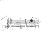
Fig. 1 , when using an optical fibervibration sensing device 20 from a communication-intensive building 10 of a communicationoptical fiber 25 and applying ahit 15 to a cover of amanhole 30 while measuring the vibration of the communicationoptical fiber 25, a hit vibration can be measured and the position on theoptical fiber 25, in the longitudinal direction, from the communication-intensive building 10 (a distance from the communication-intensive building 10 to the position where vibration is applied) can be specified. By confirming the measurement result, it is possible to confirm that a communicationoptical fiber 35 exists in underground 6 at the position and to collate the manhole position with a fiber route map, without opening themanhole 30. -
- [PTL 1]
Japanese Patent Application Laid-open No. 2020-127094 - [PTL 2]
Japanese Patent Application Laid-open No. 2020-052030 - In order to solve the above problem, an object of the present invention is to provide a facility position specification system, a cover, and a facility position specification method capable of specifying a route of an overhead cable without directly disturbing the overhead cable itself.
- On the other hand, the presence of an overhead cable can be confirmed visually, but it is not clear that an overhead cable which has been visually confirmed is a search object. In addition, as in PTL 1, directly applying a disturbance (hit or the like) to a cable may affect communication.
- An object of the present invention is to provide a facility position specification system, a cover, and a facility position specification method capable of specifying a route of an overhead cable without directly giving disturbance to the overhead cable itself.
- Specifically, a facility position specification system according to the present invention is a facility position specification system for specifying a position of an overhead cable, the system including
- an optical fiber along the overhead cable,
- a cylindrical cover covering the overhead cable at an arbitrary position on the overhead cable in a longitudinal direction,
- an optical measuring instrument connected to an end of the optical fiber and configured to acquire temporal change in scattered light from the optical fiber when vibration is applied to the overhead cable from the cover as temporal change in a scattered optical intensity distribution of the optical fiber in a longitudinal direction, and
- a signal processing unit configured to specify a vibration position on the optical fiber to which the vibration is applied based on the scattered optical intensity distribution, and specify an actual position of the overhead cable to which the vibration is applied by associating the vibration position on the optical fiber with a position of the overhead cable on a map.
- In addition, the facility position specifying method according to the present invention is a facility position specifying method for specifying a position of an overhead cable, the method including
- covering the overhead cable with a cylindrical cover at an arbitrary position on the overhead cable in a longitudinal direction,
- connecting an optical measuring instrument to an end portion of an optical fiber included in the overhead cable,
- applying vibration to the overhead cable from the cover, acquiring a temporal change of scattered light from the optical fiber when the vibration is applied as temporal change in a scattered optical intensity distribution of the optical fiber in a longitudinal direction,
- specifying a vibration position on the optical fiber to which the vibration is applied based on the scattered optical intensity distribution, and
- associating the vibration position on the optical fiber with a position of the overhead cable on a map and specifying an actual position of the overhead cable to which the vibration is applied.
- In the facility position specification system (method), a cover is attached to an arbitrary position on the overhead cable, and vibration is applied to the overhead cable through the cover. Since, in the facility position specification system (method), the overhead cable is not hit directly, optical fiber vibration sensing can be performed in a state where the likelihood of affecting communication is small.
- In addition, alternatively, the facility position specifying method according to the present invention is a facility position specifying method for specifying a position of a pillar supporting an overhead cable, the method including connecting an optical measuring instrument to an end portion of an optical fiber included in the overhead cable,
- applying vibration to any of the pillars,
- acquiring a temporal change of scattered light from the optical fiber when the vibration is applied as temporal change in a scattered optical intensity distribution of the optical fiber in a longitudinal direction,
- specifying a vibration position on the optical fiber to which the vibration is applied based on the scattered optical intensity distribution; and
- associating the vibration position on the optical fiber with a position of the overhead cable on a map and specifying the actual position of the pillar to which the vibration was applied.
- Accordingly, the present invention can provide a facility position specification system, and a facility position specification method capable of specifying a route of an overhead cable without directly giving disturbance to the overhead cable itself.
- The cover of the facility position specification system according to the present invention may include a vibration mechanism for applying the vibration. That is, the cover includes a vibration mechanism for generating vibration and a cylinder for covering an overhead cable including an optical cable at an arbitrary position and transmitting the vibration to the overhead cable. It is not necessary for a worker to directly hit, and remote control is possible.
- The cover of the facility position specification system according to the present invention may have a fold on an inner wall thereof, which is in contact with the overhead cable and transmits the vibration to the overhead cable. That is, the cover includes a cylinder for covering an overhead cable including an optical cable at an arbitrary position and a fold disposed on an inner wall of the cylinder, coming into contact with the overhead cable, and transmitting vibration of the cylinder to the overhead cable. The vibration from the cover can be efficiently transmitted to the overhead cable.
- The above inventions can be combined wherever possible.
- The present invention can provide a facility position specification system, a cover, and a facility position specification method capable of specifying a route of an overhead cable without directly giving disturbance to the overhead cable itself.
- Further, the disclosure includes the following aspects: According to a first aspect, a facility position specification system for specifying a position of an overhead cable is provided. The facility position specification system comprises:
- an optical fiber along the overhead cable;
- a cylindrical cover covering the overhead cable at an arbitrary position on the overhead cable in a longitudinal direction;
- an optical measuring instrument connected to an end of the optical fiber and configured to acquire temporal change in scattered light from the optical fiber when vibration is applied to the overhead cable from the cover as temporal change in a scattered optical intensity distribution of the optical fiber in a longitudinal direction; and a signal processing unit configured to specify a vibration position on the optical fiber to which the vibration is applied based on the scattered optical intensity distribution, and specify an actual position of the overhead cable to which the vibration is applied by associating the vibration position on the optical fiber with a position of the overhead cable on a map.
- According to a second aspect, dependent on the first aspect, the cover includes a vibration mechanism for applying the vibration.
- According to a third aspect, dependent on the first or second aspect, the cover has a fold on an inner wall thereof, the fold being in contact with the overhead cable and transmitting the vibration to the overhead cable.
- According to a forth aspect, a cover is provided, wherein the cover comprises a vibration mechanism for generating vibration; and
a cylinder for covering an overhead cable including an optical cable at an arbitrary position and transmitting the vibration to the overhead cable. - According to a fifth aspect, a cover is provided, wherein the cover comprises a cylinder for covering an overhead cable including an optical cable at an arbitrary position; and a fold disposed on an inner wall of the cylinder, coming into contact with the overhead cable, and transmitting vibration of the cylinder to the overhead cable.
- According to a sixth aspect, a facility position specifying method for specifying a position of an overhead cable is provided, wherein the method comprises:
- covering the overhead cable with a cylindrical cover at an arbitrary position on the overhead cable in a longitudinal direction;
- connecting an optical measuring instrument to an end portion of an optical fiber included in the overhead cable;
- applying vibration to the overhead cable from the cover; acquiring a temporal change of scattered light from the optical fiber when the vibration is applied as temporal change in a scattered optical intensity distribution of the optical fiber in a longitudinal direction;
- specifying a vibration position on the optical fiber to which the vibration is applied based on the scattered optical intensity distribution; and
- associating the vibration position on the optical fiber with a position of the overhead cable on a map and specifying an actual position of the overhead cable to which the vibration is applied.
- According to a seventh aspect, a facility position specifying method for specifying a position of a pillar supporting an overhead cable is provided, the method comprising:
- connecting an optical measuring instrument to an end portion of an optical fiber included in the overhead cable;
- applying vibration to any of the pillars;
- acquiring a temporal change of scattered light from the optical fiber when the vibration is applied as temporal change in a scattered optical intensity distribution of the optical fiber in a longitudinal direction;
- specifying a vibration position on the optical fiber to which the vibration is applied based on the scattered optical intensity distribution; and
- associating the vibration position on the optical fiber with a position of the overhead cable on a map and specifying the actual position of the pillar to which the vibration was applied.
-
- [
Fig. 1] Fig. 1 is a diagram illustrating a facility position specification principle using an optical fiber vibration sensor. - [
Fig. 2] Fig. 2 is a diagram illustrating a facility position specification system according to the present invention. - [
Fig. 3] Fig. 3 is a diagram illustrating a cover included in the facility position specification system according to the present invention. - [
Fig. 4] Fig. 4 is a diagram illustrating a facility position specifying method according to the present invention. - [
Fig. 5] Fig. 5 is a diagram illustrating the facility position specifying method according to the present invention. - [
Fig. 6] Fig. 6 is a diagram illustrating the facility position specifying method according to the present invention. - [
Fig. 7] Fig. 7 is a table for illustrating an operation method of the facility position specification system according to the present invention. - [
Fig. 8] Fig. 8 is a diagram illustrating a scattered optical intensity distribution to be measured by an optical measuring instrument of the facility position specification system according to the present invention. - [
Fig. 9] Fig. 9 is a diagram illustrating matching performed by the facility position specification system according to the present invention. - [
Fig. 10] Fig. 10 is a diagram illustrating a facility position specifying method according to the present invention. - [
Fig. 11] Fig. 11 is a diagram illustrating the facility position specification system according to the present invention. - Embodiments of the present invention will be described with reference to accompanying drawings. The embodiments described below are examples of the present invention, and the present invention is not limited to the following embodiments. In the present specification and the drawings, the components having the same reference numerals indicate the same components.
-
Fig. 2 is a diagram illustrating a facility position specification system according to the present invention. The facility position specification system is a facility position specification system for specifying a position of anoverhead cable 26, the system including - an
optical fiber 25 along theoverhead cable 26, - a
cylindrical cover 40 covering theoverhead cable 26 at an arbitrary position on theoverhead cable 26 in the longitudinal direction, - an optical measuring
instrument 20 connected to an end of theoptical fiber 25 and configured to acquire temporal change in scattered light from theoptical fiber 25 when vibration is applied to theoverhead cable 26 from thecover 40 as temporal change in a scattered optical intensity distribution of theoptical fiber 25 in a longitudinal direction, and - a
signal processing unit 21 configured to specify a vibration position on theoptical fiber 25 to which the vibration is applied based on the scattered optical intensity distribution, and specify an actual position of theoverhead cable 26 to which the vibration is applied by associating the vibration position on theoptical fiber 25 with a position of theoverhead cable 26 on a map. - The
overhead cable 26 is a cable stretched in the air by a pillar or the like. Theoverhead cable 26 is a metal wire or an optical fiber cable for power supply. Theoptical fiber 25 used in this system is laid along theoverhead cable 26. In a case where theoverhead cable 26 is an optical fiber cable, the optical fiber in the optical fiber cable can be used as theoptical fiber 25. - The
cover 40 is disposed so as to cover theoverhead cable 26. Thecover 40 may be attached when laying theoverhead cable 26, or thecover 40 may be attached to theoverhead cable 26 by a worker every inspection. Thecover 40 has a function of transmitting vibration such as a given hit to theoverhead cable 26. For this reason, thecover 40 is preferably made of a material having a high modulus of elasticity (a high Young's modulus) and a low density, for example, a metal, in order to efficiently transmit vibration to the cable. -
Fig. 3 is a diagram illustrating a structure of thecover 40. Thecover 40 includes - a
cylinder 41 for covering theoverhead cable 26 at an arbitrary position, and - a
fold 42 that is disposed on an inner wall of thecylinder 41, comes into contact with theoverhead cable 26, and transmits vibration of thecylinder 41 to theoverhead cable 26. - The
cover 40 covers theoverhead cable 26 with thecylinder 41. Thecylinder 41 and theoverhead cable 26 are not in direct contact with each other. Thecover 40 has afold 42, and a space is generated between thecylinder 41 and theoverhead cable 26 by thefold 42 coming into contact with theoverhead cable 26. The vibration from thecylinder 41 is transmitted to theoverhead cable 26 through thefolds 42. Thus, the vibration from thecylinder 41 can be efficiently transmitted to theoverhead cable 26. In order to transmit vibration efficiently, the number offolds 42 and the length L of thecover 40 may be adjusted. -
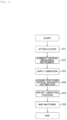
Fig. 4 is a flowchart illustrating the facility position specifying method. The present facility position specifying method includes - covering the
overhead cable 26 with thecylindrical cover 40 at an arbitrary position on theoverhead cable 26 in a longitudinal direction (step S01), - connecting an optical measuring
instrument 20 to an end portion of theoptical fiber 25 included in the overhead cable 26 (step S02), - applying vibration to the
overhead cable 26 from the cover 40 (step S03), - acquiring a temporal change of scattered light from the
optical fiber 25 when the vibration is applied as temporal change in a scattered optical intensity distribution of theoptical fiber 25 in a longitudinal direction (step S04), specifying a vibration position on theoptical fiber 25 to which the vibration is applied based on the scattered optical intensity distribution (step S05), and - associating the vibration position on the
optical fiber 25 with a position of theoverhead cable 26 on amap 50 and specifying an actual position of theoverhead cable 26 to which the vibration is applied (step S06). - In step S01, the
cover 40 is attached to theoverhead cable 26 whose position is desired to be ascertained. The number ofcovers 40 is arbitrary. Thecover 40 may be attached when laying theoverhead cable 26, or thecover 40 may be attached to theoverhead cable 26 by a worker every inspection. - One end of the
overhead cable 26 is drawn into a communication-intensive building 10. In step S02, theoptical fiber 25 is taken out from theoverhead cable 26 drawn into the communication-intensive building 10, and is connected to the optical measuring instrument 20 (the end of theoptical fiber 25 connected to the optical measuringinstrument 20 is defined as "one end"). The optical measuringinstrument 20 is, for example, an optical time domain reflectometer (OTDR). - In step S03, test light is input from the optical measuring
instrument 20 to one end of theoptical fiber 25, and the vibration is applied to thecover 40 during an optical test in which back scattered light output from the one end of theoptical fiber 25 is measured by the optical measuringinstrument 20. Here, the vibration applying method will be described. - As illustrated in
Fig. 5 , an operator applies ahit 15 to the cover by a hammer or the like. For example, the operator may hit the cover by a long bar type hammer reaching from the ground. Further, the operator may move to the vicinity of thecover 40 by a bucket truck and hit the cover by a hammer. - As illustrated in
Fig. 6 , thecover 40 includes avibration mechanism 43 for generating vibration in thecylinder 41. Thevibration mechanism 43 is disposed in thecylinder 41, for example, and is composed of a piezoelectric moving by radio waves and a battery such as a solar cell for supplying electric power to the piezoelectric. In a case where thecover 40 is provided with thevibration mechanism 43, a worker can apply vibration remotely without riding on a bucket truck or the like. -
Fig. 7 is a table in which the work styles in the step S03 are summarized. As an operation method, there are cases where thecover 40 is always attached to theoverhead cable 26 and where thecover 40 is always attached to theoverhead cable 26 at the time of inspection. In either case, if the vibration applying method is used for hitting thecover 40 with a hammer or the like, thecover 40 does not require a vibration mechanism, but it is necessary to dispatch the worker to the work site. - On the other hand, in a case where the
cover 40 is provided with thevibration mechanism 43, remote control is possible, and dispatch of a worker to the work site is not required. However, in a case where it is necessary to supply power to thevibration mechanism 43 during work, it is necessary to dispatch a worker. - In steps S04 and S05, the optical measuring
instrument 20 acquires an optical intensity distribution of back scattered light output from one end of anoptical fiber 25.Fig. 8 shows an example of an optical intensity distribution obtained by the optical measuringinstrument 20. The horizontal axis represents the distance from one end of theoptical fiber 25. The vertical axis represents the light intensity of the back scattered light. It can be seen that there is a waveform peak at the position of the distance z and vibration was applied at this position. - In step S06, a
signal processing unit 21 matches amap 50 showing the layout of theoverhead cable 26 with the optical intensity distribution ofFig. 8 .Fig. 9 is a diagram illustrating matching work. On which route the overhead cable is laid when theoverhead cable 26 is laid is recorded in themap 50. - As illustrated in
Fig. 9 , by collating the longitudinal distance of theoptical fiber 25 with the length of the laidcable 26, thesignal processing unit 21 can determine which place the peak position (hit position 52) of the optical intensity distribution illustrated inFig. 8 corresponds to on themap 50. -
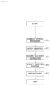
Fig. 10 is a flowchart for illustrating a facility position specifying method according to the present embodiment.Fig. 11 is a diagram for illustrating a facility position specification system to be inspected by the present facility position specifying method. The present facility position specifying method is a method for specifying a facility position without attaching thecover 40 in comparison with the facility position specifying method of Embodiment 1. The present facility position specification method includes connecting the optical measuringinstrument 20 to an end portion of theoptical fiber 25 included in the overhead cable 26 (step S02), - applying vibration to any of
pillars 35 supporting the overhead cable 26 (step S13), - acquiring a temporal change of scattered light from the
optical fiber 25 when the vibration is applied as temporal change in a scattered optical intensity distribution of theoptical fiber 25 in a longitudinal direction (step S04), specifying a vibration position on theoptical fiber 25 to which the vibration is applied based on the scattered optical intensity distribution (step S05), and - associating the vibration position on the
optical fiber 25 with a position of theoverhead cable 26 on amap 50, and specifying an actual position of thepillar 35 to which the vibration is applied (step S16). - In the facility position specifying method according to the present embodiment, the
pillar 35 supporting theoverhead cable 26 is hit instead of hitting the cover. When thepillar 35 is hit by ahammer 45 or the like, the vibration is transmitted to theoptical fiber 25 of theoverhead cable 26, and the scattered optical intensity distribution as illustrated inFig. 8 can be acquired by the optical measuringinstrument 20. Therefore, as illustrated with reference toFig. 9 , by collating the scattered optical intensity distribution with themap 50 in which the laying of theoverhead cable 26 is described, it is possible to specify the actual position of the pillar 35 (the position on the map). - The present facility position specifying method does not require the work of attaching the cover to the
overhead cable 26 in comparison with the facility position specifying method described in Embodiment 1, and can simply ascertain the standard of the position of theoverhead cable 26 and the position of the electric pillar. - Since the vibration is applied to the cover or the pillar attached to the overhead cable and vibration is applied to the overhead cable without directly applying hit to the overhead cable, the scattered optical intensity distribution can be acquired without damaging the overhead cable.
- The position and existence of the overhead cable and the electric pillar can be determined at the site where the worker is dispatched, and further, the overhead cable and the electric pillar can be matched with a map.
- If it is a method of attaching the cover, the position and existence of the overhead cable can be determined even in a place where no electric pillar exists, and the overhead cable can be matched with the map.
- When the vibrator is applied to the cover, the vibration can be applied to the overhead cable remotely.
-
- 5: Ground
- 6: Underground
- 10: Communication-intensive building
- 15: Hit
- 20: Optical measuring instrument
- 21: Signal processing unit
- 25: Optical fiber
- 26: Overhead cable
- 30: Manhole
- 35: Pillar
- 40: Cover
- 41: Cylinder
- 42: Fold
- 43: Vibration mechanism
- 50: Map
- 51: Road
- 52: Hit position
Claims (2)
- A cover comprising:a vibration mechanism for generating vibration; anda cylinder for covering an overhead cable including an optical cable at an arbitrary position and transmitting the vibration to the overhead cable.
- A cover comprising:a cylinder for covering an overhead cable including an optical cable at an arbitrary position; anda fold disposed on an inner wall of the cylinder, coming into contact with the overhead cable, and transmitting vibration of the cylinder to the overhead cable.
Priority Applications (1)
| Application Number | Priority Date | Filing Date | Title |
|---|---|---|---|
| EP24217005.8A EP4495557A3 (en) | 2021-01-21 | 2021-01-21 | Equipment location identification system, cover, and equipment location identification method |
Applications Claiming Priority (3)
| Application Number | Priority Date | Filing Date | Title |
|---|---|---|---|
| PCT/JP2021/002003 WO2022157877A1 (en) | 2021-01-21 | 2021-01-21 | Equipment location specifying system, cover, and equipment location specifying method |
| EP21920990.5A EP4283250A4 (en) | 2021-01-21 | 2021-01-21 | Equipment location specifying system, cover, and equipment location specifying method |
| EP24217005.8A EP4495557A3 (en) | 2021-01-21 | 2021-01-21 | Equipment location identification system, cover, and equipment location identification method |
Related Parent Applications (1)
| Application Number | Title | Priority Date | Filing Date |
|---|---|---|---|
| EP21920990.5A Division EP4283250A4 (en) | 2021-01-21 | 2021-01-21 | Equipment location specifying system, cover, and equipment location specifying method |
Publications (2)
| Publication Number | Publication Date |
|---|---|
| EP4495557A2 true EP4495557A2 (en) | 2025-01-22 |
| EP4495557A3 EP4495557A3 (en) | 2025-04-02 |
Family
ID=82548548
Family Applications (3)
| Application Number | Title | Priority Date | Filing Date |
|---|---|---|---|
| EP21920990.5A Pending EP4283250A4 (en) | 2021-01-21 | 2021-01-21 | Equipment location specifying system, cover, and equipment location specifying method |
| EP24217041.3A Withdrawn EP4495558A3 (en) | 2021-01-21 | 2021-01-21 | Equipment location identification system, cover, and equipment location identification method |
| EP24217005.8A Pending EP4495557A3 (en) | 2021-01-21 | 2021-01-21 | Equipment location identification system, cover, and equipment location identification method |
Family Applications Before (2)
| Application Number | Title | Priority Date | Filing Date |
|---|---|---|---|
| EP21920990.5A Pending EP4283250A4 (en) | 2021-01-21 | 2021-01-21 | Equipment location specifying system, cover, and equipment location specifying method |
| EP24217041.3A Withdrawn EP4495558A3 (en) | 2021-01-21 | 2021-01-21 | Equipment location identification system, cover, and equipment location identification method |
Country Status (5)
| Country | Link |
|---|---|
| US (1) | US20240060817A1 (en) |
| EP (3) | EP4283250A4 (en) |
| JP (1) | JPWO2022157877A1 (en) |
| CN (1) | CN116569002A (en) |
| WO (1) | WO2022157877A1 (en) |
Families Citing this family (3)
| Publication number | Priority date | Publication date | Assignee | Title |
|---|---|---|---|---|
| US20220333956A1 (en) * | 2021-04-14 | 2022-10-20 | Nec Laboratories America, Inc | Mapping using optical fiber sensing |
| WO2024166295A1 (en) * | 2023-02-09 | 2024-08-15 | 日本電信電話株式会社 | Equipment location analysis device and equipment location analysis method |
| WO2026022889A1 (en) * | 2024-07-22 | 2026-01-29 | Ntt株式会社 | Optical line facility location identification method |
Citations (2)
| Publication number | Priority date | Publication date | Assignee | Title |
|---|---|---|---|---|
| JP2020052030A (en) | 2018-09-20 | 2020-04-02 | 日本電信電話株式会社 | Manhole position specifying method and manhole position specifying system |
| JP2020127094A (en) | 2019-02-01 | 2020-08-20 | 日本電信電話株式会社 | Method of searching optical fiber route, optical fiber route search device and program |
Family Cites Families (9)
| Publication number | Priority date | Publication date | Assignee | Title |
|---|---|---|---|---|
| JP3386966B2 (en) * | 1996-12-17 | 2003-03-17 | 中部電力株式会社 | Accident detection position locating system for overhead transmission lines |
| JP3914050B2 (en) * | 2001-12-28 | 2007-05-16 | 日本特殊陶業株式会社 | Langevin type ultrasonic transducer |
| JP2010074938A (en) * | 2008-09-18 | 2010-04-02 | Nippon Telegr & Teleph Corp <Ntt> | Cable searching method and cable searching apparatus |
| JP5128519B2 (en) * | 2009-02-24 | 2013-01-23 | 日本電信電話株式会社 | Optical equipment identification method and apparatus |
| JP6723540B2 (en) * | 2016-06-06 | 2020-07-15 | 西松建設株式会社 | Excitation device, vibration measuring system, vibration measuring method, and tension measuring method |
| JP7124875B2 (en) * | 2018-08-30 | 2022-08-24 | 日本電気株式会社 | Utility pole location identification system, utility pole location identification device, utility pole location identification method, and program |
| JP7211134B2 (en) * | 2019-02-12 | 2023-01-24 | 日本電信電話株式会社 | Aerial optical fiber cable inspection method, aerial optical fiber cable inspection device and program |
| US12467822B2 (en) * | 2020-08-31 | 2025-11-11 | Nec Corporation | Utility pole deterioration discrimination device and method |
| WO2022113252A1 (en) * | 2020-11-27 | 2022-06-02 | 日本電気株式会社 | Position specifying system, vibration generator, and position specifying method |
-
2021
- 2021-01-21 WO PCT/JP2021/002003 patent/WO2022157877A1/en not_active Ceased
- 2021-01-21 US US18/269,858 patent/US20240060817A1/en not_active Abandoned
- 2021-01-21 CN CN202180081160.1A patent/CN116569002A/en active Pending
- 2021-01-21 EP EP21920990.5A patent/EP4283250A4/en active Pending
- 2021-01-21 JP JP2022576290A patent/JPWO2022157877A1/ja active Pending
- 2021-01-21 EP EP24217041.3A patent/EP4495558A3/en not_active Withdrawn
- 2021-01-21 EP EP24217005.8A patent/EP4495557A3/en active Pending
Patent Citations (2)
| Publication number | Priority date | Publication date | Assignee | Title |
|---|---|---|---|---|
| JP2020052030A (en) | 2018-09-20 | 2020-04-02 | 日本電信電話株式会社 | Manhole position specifying method and manhole position specifying system |
| JP2020127094A (en) | 2019-02-01 | 2020-08-20 | 日本電信電話株式会社 | Method of searching optical fiber route, optical fiber route search device and program |
Also Published As
| Publication number | Publication date |
|---|---|
| US20240060817A1 (en) | 2024-02-22 |
| EP4495558A3 (en) | 2025-04-16 |
| EP4283250A1 (en) | 2023-11-29 |
| JPWO2022157877A1 (en) | 2022-07-28 |
| EP4283250A4 (en) | 2025-01-01 |
| EP4495557A3 (en) | 2025-04-02 |
| CN116569002A (en) | 2023-08-08 |
| WO2022157877A1 (en) | 2022-07-28 |
| EP4495558A2 (en) | 2025-01-22 |
Similar Documents
| Publication | Publication Date | Title |
|---|---|---|
| EP4495557A2 (en) | Equipment location identification system, cover, and equipment location identification method | |
| US11112332B2 (en) | Optical fiber monitoring method, and optical fiber monitoring system | |
| US11366231B2 (en) | Smart optical cable positioning/location using optical fiber sensing | |
| US11644347B2 (en) | Manhole position specification method and manhole position specification system | |
| JP2020519798A (en) | Precast segment for tunnels and method of making and monitoring such precast segment | |
| CN115219127B (en) | Bridge real-time monitoring and evaluation system and construction method thereof | |
| US20210223095A1 (en) | Optical-fiber path searching method, optical-fiber path searching system, signal processing device, and program | |
| JP2002366616A (en) | Management method and management system for manhole information | |
| WO1993003400A1 (en) | Method of probing optical transmission line | |
| JP3386966B2 (en) | Accident detection position locating system for overhead transmission lines | |
| KR102102187B1 (en) | Rock-Falling Sensing System Using Data-logger | |
| Warren et al. | Geosynthetic strain gage installation procedures and alternative strain measurement methods for roadway applications | |
| JPH0611534A (en) | Partial discharge measurement method | |
| KR101551341B1 (en) | Apparatus for checking of cable | |
| CN113167604B (en) | Fiber optic sensing expansion device and fiber optic sensing system | |
| CN111679313A (en) | Method for confirming power optical cable routing by mechanical periodic vibration excitation | |
| US20080151231A1 (en) | Fiber optic testing system and method incorporating geolocation information | |
| Dubaniewicz et al. | Distributed measurement of conductor temperatures in mine trailing cables using fiber-optic technology | |
| JP5904955B2 (en) | PORTABLE TERMINAL DEVICE AND INVISIBLE FACILITY LOCATION METHOD USING THE DEVICE | |
| CN104749444A (en) | Grounding resistance measuring device | |
| JP2001194191A (en) | Method and apparatus for measuring displacement of civil engineering structure | |
| KR101953022B1 (en) | Location detecting sonde for sewer facility | |
| KR20230064272A (en) | Wireless sensor apparatus with improved vibration proofing and waterproof performance | |
| CN216873204U (en) | Portable optical cable breakpoint positioning device | |
| JPH0443935A (en) | Measuring method for laying length of optical fiber cable |
Legal Events
| Date | Code | Title | Description |
|---|---|---|---|
| PUAI | Public reference made under article 153(3) epc to a published international application that has entered the european phase |
Free format text: ORIGINAL CODE: 0009012 |
|
| STAA | Information on the status of an ep patent application or granted ep patent |
Free format text: STATUS: THE APPLICATION HAS BEEN PUBLISHED |
|
| AC | Divisional application: reference to earlier application |
Ref document number: 4283250 Country of ref document: EP Kind code of ref document: P |
|
| AK | Designated contracting states |
Kind code of ref document: A2 Designated state(s): AL AT BE BG CH CY CZ DE DK EE ES FI FR GB GR HR HU IE IS IT LI LT LU LV MC MK MT NL NO PL PT RO RS SE SI SK SM TR |
|
| REG | Reference to a national code |
Ref country code: DE Ref legal event code: R079 Free format text: PREVIOUS MAIN CLASS: G01H0009000000 Ipc: G01B0011000000 |
|
| PUAL | Search report despatched |
Free format text: ORIGINAL CODE: 0009013 |
|
| AK | Designated contracting states |
Kind code of ref document: A3 Designated state(s): AL AT BE BG CH CY CZ DE DK EE ES FI FR GB GR HR HU IE IS IT LI LT LU LV MC MK MT NL NO PL PT RO RS SE SI SK SM TR |
|
| RIC1 | Information provided on ipc code assigned before grant |
Ipc: G01H 9/00 20060101ALI20250224BHEP Ipc: G01B 11/00 20060101AFI20250224BHEP |
|
| STAA | Information on the status of an ep patent application or granted ep patent |
Free format text: STATUS: REQUEST FOR EXAMINATION WAS MADE |
|
| 17P | Request for examination filed |
Effective date: 20250416 |
|
| STAA | Information on the status of an ep patent application or granted ep patent |
Free format text: STATUS: EXAMINATION IS IN PROGRESS |
|
| 17Q | First examination report despatched |
Effective date: 20250612 |
|
| RAP3 | Party data changed (applicant data changed or rights of an application transferred) |
Owner name: NTT, INC. |
|
| GRAP | Despatch of communication of intention to grant a patent |
Free format text: ORIGINAL CODE: EPIDOSNIGR1 |
|
| STAA | Information on the status of an ep patent application or granted ep patent |
Free format text: STATUS: GRANT OF PATENT IS INTENDED |
|
| INTG | Intention to grant announced |
Effective date: 20260212 |
|
| GRAS | Grant fee paid |
Free format text: ORIGINAL CODE: EPIDOSNIGR3 |
|
| GRAA | (expected) grant |
Free format text: ORIGINAL CODE: 0009210 |
|
| STAA | Information on the status of an ep patent application or granted ep patent |
Free format text: STATUS: THE PATENT HAS BEEN GRANTED |