EP4494793A1 - Cutting insert, cutting tool, and method for manufacturing cut workpiece - Google Patents
Cutting insert, cutting tool, and method for manufacturing cut workpiece Download PDFInfo
- Publication number
- EP4494793A1 EP4494793A1 EP23770574.4A EP23770574A EP4494793A1 EP 4494793 A1 EP4494793 A1 EP 4494793A1 EP 23770574 A EP23770574 A EP 23770574A EP 4494793 A1 EP4494793 A1 EP 4494793A1
- Authority
- EP
- European Patent Office
- Prior art keywords
- cutting edge
- corner
- cutting
- cutting insert
- edge
- Prior art date
- Legal status (The legal status is an assumption and is not a legal conclusion. Google has not performed a legal analysis and makes no representation as to the accuracy of the status listed.)
- Pending
Links
Images




Classifications
-
- B—PERFORMING OPERATIONS; TRANSPORTING
- B23—MACHINE TOOLS; METAL-WORKING NOT OTHERWISE PROVIDED FOR
- B23C—MILLING
- B23C5/00—Milling-cutters
- B23C5/02—Milling-cutters characterised by the shape of the cutter
- B23C5/06—Face-milling cutters, i.e. having only or primarily a substantially flat cutting surface
-
- B—PERFORMING OPERATIONS; TRANSPORTING
- B23—MACHINE TOOLS; METAL-WORKING NOT OTHERWISE PROVIDED FOR
- B23C—MILLING
- B23C5/00—Milling-cutters
- B23C5/16—Milling-cutters characterised by physical features other than shape
- B23C5/20—Milling-cutters characterised by physical features other than shape with removable cutter bits or teeth or cutting inserts
- B23C5/202—Plate-like cutting inserts with special form
-
- B—PERFORMING OPERATIONS; TRANSPORTING
- B23—MACHINE TOOLS; METAL-WORKING NOT OTHERWISE PROVIDED FOR
- B23C—MILLING
- B23C2200/00—Details of milling cutting inserts
- B23C2200/04—Overall shape
- B23C2200/0422—Octagonal
-
- B—PERFORMING OPERATIONS; TRANSPORTING
- B23—MACHINE TOOLS; METAL-WORKING NOT OTHERWISE PROVIDED FOR
- B23C—MILLING
- B23C2200/00—Details of milling cutting inserts
- B23C2200/04—Overall shape
- B23C2200/0455—Square
-
- B—PERFORMING OPERATIONS; TRANSPORTING
- B23—MACHINE TOOLS; METAL-WORKING NOT OTHERWISE PROVIDED FOR
- B23C—MILLING
- B23C2200/00—Details of milling cutting inserts
- B23C2200/20—Top or side views of the cutting edge
- B23C2200/203—Curved cutting edges
Definitions
- the present disclosure relates to a cutting insert, a cutting tool, and a method for manufacturing a machined product.
- Rotary tools include an end mill and a milling tool.
- a cutting insert disclosed in Patent Document 1 is known as a cutting insert applied to a cutting tool.
- the cutting insert described in Patent Document 1 is a so-called double-sided insert having cutting edges on an upper surface side and a lower surface side.
- the cutting edges in Patent Document 1 have a minor cutting edge (so-called flat cutting edge) for finish machining.
- the minor cutting edge has a protruding curved shape protruding upward in a side view.
- Patent Document 1 illustrates, as specific shapes of the minor cutting edge, an arc shape having a constant curvature and a protruding curved shape having a curvature gradually decreasing toward both ends in the side view.
- Patent Document 1 WO 2013/077443
- a cutting insert includes: an upper surface; a lower surface located on an opposite side of the upper surface; a lateral surface connected to the upper surface and the lower surface; a upper cutting edge located on an intersection between the upper surface and the lateral surface; and a lower cutting edge located on an intersection between the lower surface and the lateral surface.
- the upper surface includes a first corner, a first side connected to the first corner, and a second side connected to the first corner on an opposite side of the first side.
- the upper cutting edge includes a main cutting edge located on the first side and having a linear shape in a top view, a minor cutting edge located on the second side and having a linear shape in the top view, and a connection edge located on the first corner, connected to the main cutting edge and the minor cutting edge, and having a protruding shape (protruding curved shape) protruding outward in the top view.
- the minor cutting edge has a protruding curved shape protruding upward in a side view and includes a first portion including an apex portion protruding most upward in the minor cutting edge, a second portion located between the first portion and the connection edge, and a third portion located between the second portion and the connection edge.
- Each of the second portion and the third portion comes close to the lower surface with distance from the first portion.
- a radius of curvature of the second portion is larger than a radius of curvature of the first portion and a radius of curvature of the third portion.
- a cutting tool includes: a holder having a cylindrical shape extending from a first end to a second end along a rotation axis and including a pocket located on a side of the first end; and the cutting insert according to an aspect of the present disclosure located in the pocket.
- a method for manufacturing a machined product according to an aspect of the present disclosure includes: rotating the cutting tool according to an aspect of the present disclosure; bringing the cutting tool rotating into contact with a workpiece; and separating the cutting tool from the workpiece.
- the present disclosure can improve the surface accuracy of the machined surface of the workpiece.
- FIG. 1 A cutting insert, a cutting tool, and a method for manufacturing a machined product according to an embodiment of the present disclosure will be described below in detail with reference to the drawings.
- the dimensions of the components in the drawings do not faithfully represent the actual dimensions of the components, the dimension ratios of the members, or the like.
- the insert central axis refers to a virtual axis passing through the center of the upper surface of the cutting insert and the center of the lower surface of the cutting insert.
- the term “inward direction” or “inner side” refers to a direction toward or a side closer to the insert central axis in the cutting insert.
- the term “outward direction” or “outer side” refers to a direction or a side away from the insert central axis in the cutting insert.
- the term “orthogonal” is not limited to being strictly orthogonal and means that an error of approximately ⁇ 5 degrees is allowed.
- parallel is not limited to being strictly parallel and means that an error of about ⁇ 5 degrees is allowed.
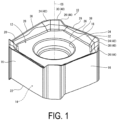
- FIG. 1 is a schematic perspective view of the cutting insert 10 according to the embodiment of the present disclosure.
- FIG. 2 is a schematic plan view of the cutting insert 10 illustrated in FIG. 1 .
- FIG. 3 is a schematic side view of the cutting insert 10 illustrated in FIG. 1 . Note that FIG. 3 is a side view from the direction in which a second side described below is viewed from the front.
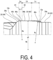
- FIG. 4 is an enlarged view of a part IV in FIG. 3 .
- the cutting insert 10 is a component of a cutting tool used for machining of a workpiece W (see FIG. 7 ) made of a metal material or the like.
- Examples of the machining of the workpiece W include shoulder machining, grooving, R machining, and profiling.
- the cutting insert 10 may include an upper surface 12 and a lower surface 14 located on the opposite side of the upper surface 12.
- Each of the upper surface 12 and the lower surface 14 may have a polygonal shape, for example, an octagonal shape.
- the cutting insert 10 may have a polygonal plate shape, for example, an octagonal plate shape.
- Each of the upper surface 12 and the lower surface 14 may have a polygonal shape, for example, a triangular shape, a quadrangular shape, or the like other than the octagonal shape.
- the cutting insert 10 may have a polygonal plate shape, for example, a triangular plate shape, a quadrangular plate shape, or the like other than the octagonal plate shape.
- the polygonal shape is not limited strictly to a shape of a polygon.
- each of the upper surface 12 and the lower surface 14 may have a rotationally symmetrical shape at a constant angle with respect to an insert central axis CS.
- the upper surface 12 and the lower surface 14 may be shaped such that the front and back sides are reversed and symmetrical.
- the cutting insert 10 may have a rotationally symmetrical shape at a constant angle with respect to the insert central axis CS or may be shaped such that the front and back sides are reversed and symmetrical.
- the cutting insert 10 may include a plurality of lateral surfaces 16 located between the upper surface 12 and the lower surface 14.
- the lateral surface 16 may be connected to the upper surface 12 and the lower surface 14.
- the lateral surfaces 16 may function as flank faces and may be parallel to the insert central axis CS.
- the cutting insert 10 is a so-called negative type cutting insert having a clearance angle of 0 degrees.
- the cutting insert 10 may include a mounting hole 18 penetrated from the upper surface 12 to the lower surface 14 as in the examples illustrated in FIGs. 1 to 3 .
- One opening of the mounting hole 18 may be located in a central portion of the upper surface 12, and the other opening of the mounting hole 18 may be located in a central portion of the lower surface 14.
- the central axis of the mounting hole 18 may coincide with the insert central axis CS.
- the cutting insert 10 may include a upper cutting edge 20 and a lower cutting edge 22.
- the upper cutting edge 20 may be located on an intersection between the upper surface 12 and the lateral surface 16.
- the lower cutting edge 22 may be located on an intersection between the lower surface 14 and the lateral surface 16.
- the cutting insert 10 may be a double-sided insert provided with the upper cutting edge 20 and the lower cutting edge 22.
- the upper cutting edge 20 may be located on the entire intersection between the upper surface 12 and the lateral surface 16 or may be located on part of the intersection between thereof.
- the lower cutting edge 22 may be located on the entire intersection between the lower surface 14 and the lateral surface 16 or may be located on part of the intersection between thereof.
- the upper surface 12 formed in a polygonal shape may include a first corner 24 as one of a plurality of corners and a second corner 26 as one other of a plurality of corners.
- Each of the first corner 24 and the second corner 26 may have a protruding curved shape protruding in an outward direction in a top view.
- the upper surface 12 may include a first side 28 connected to the first corner 24 and a second side 30 connected to the first corner 24 on the opposite side of the first side 28.
- the second corner 26 may be connected to the second side 30 on the opposite side of the first corner 24.
- the first side 28 may have a linear shape in the top view or may come close to the lower surface 14 with distance from the first corner 24 in a side view.
- the second side 30 may have a linear shape in the top view.
- first side 28 and the second side 30 are not limited to the linear shape, and may have, for example, a gently protruding curved shape protruding in an outward direction.
- “having a gently protruding curved shape” means having a radius of curvature larger than radii of curvature of the first corner 24 and the second corner 26 that have a protruding curved shape.
- the upper surface 12 has a rotationally symmetrical shape at a certain angle about the insert central axis CS
- the upper surface 12 may have a plurality of the first corners 24 and a plurality of the second corners 26 as in the example illustrated in FIG. 2 .
- the plurality of first corners 24 and the plurality of second corners 26 may be alternately located along the peripheral direction of the upper surface 12.
- the upper surface 12 may also include a plurality of the first sides 28 and a plurality of the second sides 30.
- the upper surface 12 includes the plurality of first corners 24, the plurality of second corners 26, the plurality of first sides 28, and the plurality of second sides 30, the evaluation described below may be performed by focusing on portions extracted one by one from these portions such that the aforementioned positional relationship is provided.
- the upper surface 12 may include a land portion 32 located at the peripheral edge portion thereof, and the land portion 32 may be connected to the upper cutting edge 20.
- the land portion 32 may function to enhance edge strength of the upper cutting edge 20.
- the land portion 32 may be a portion that is adjacent to the upper cutting edge 20 and is indicated by a straight line in a cross-section orthogonal to the upper cutting edge 20 in the top view.
- the upper surface 12 may also include a rake surface 34 located on the inner side of the land portion 32, and the rake surface 34 may be connected to the land portion 32.
- the rake surface 34 may be inclined with respect to the land portion 32 and may come close to the lower surface 14 with distance from the land portion 32.
- the upper surface 12 may include a bottom surface 36 located on the inner side of the rake surface 34, and the bottom surface 36 may be connected to the rake surface 34.
- the bottom surface 36 may surround the opening of the mounting hole 18, and may be orthogonal to the insert central axis CS.
- the upper cutting edge 20 may include a main cutting edge 38 located on the first side 28.
- the main cutting edge 38 is a portion that can function as a main cutting edge in machining the workpiece W.
- the main cutting edge 38 may be located over the entirety of the first side 28 or may be located over a portion of the first side 28.
- the main cutting edge 38 may have a linear shape in the top view.
- the upper cutting edge 20 may include a minor cutting edge 40 located on the second side 30.
- the minor cutting edge 40 may function as a flat cutting edge for finishing the machined surface of the workpiece W.
- the minor cutting edge 40 may be located over the entirety of the second side 30 or may be located over a portion of the second side 30.
- the minor cutting edge 40 may have a linear shape in the top view.
- the upper cutting edge 20 may include a first connection edge (connection edge) 42 located on the first corner 24, and the first connection edge 42 may be connected to the main cutting edge 38 and the minor cutting edge 40.
- the first connection edge 42 may have a protruding curved shape protruding outward in the top view.
- the upper cutting edge 20 may also include a second connection edge 44 located on the second corner 26, and the second connection edge 44 may be connected to the minor cutting edge 40.
- the second connection edge 44 may have a protruding curved shape protruding outward in the top view.
- the minor cutting edge 40 may have a protruding curved shape protruding upward in the side view.
- the minor cutting edge 40 may include a first portion 40a including an apex portion 40t protruding most upward in the minor cutting edge 40, a second portion 40b located between the first portion 40a and the first connection edge 42, and a third portion 40c located between the second portion 40b and the first connection edge 42.
- a length Lb of the second portion 40b of the minor cutting edge 40 may be longer than a length La of the first portion 40a and a length Lc of the third portion 40c.
- the length of the third portion 40c of the minor cutting edge 40 may be greater than the length of the first portion 40a.
- Each of the second portion 40b and the third portion 40c of the minor cutting edge 40 may come close to the lower surface 14 with distance from the first portion 40a.
- the aforementioned “length La” means the width of the first portion 40a in the direction orthogonal to the insert central axis CS in a side view of the insert 10.
- the aforementioned “length Lb” means the width of the second portion 40b in the direction orthogonal to the insert central axis CS in a side view of the insert 10, and the aforementioned “length Lc” means the width of the third portion 40c in the direction orthogonal to the insert central axis CS in a side view of the insert 10.
- a radius of curvature Rb of the second portion 40b of the minor cutting edge 40 may be larger than a radius of curvature Ra of the first portion 40a and a radius of curvature Rc of the third portion 40c.
- the radius of curvature of the second portion 40b of the minor cutting edge 40 may be smaller than the radius of curvature of the first portion 40a and the radius of curvature of the third portion 40c.
- the radius of curvature Rc of the third portion 40c of the minor cutting edge 40 may be larger than the radius of curvature Ra of the first portion 40a.
- the radius of curvature of the third portion 40c of the minor cutting edge 40 may be smaller than the radius of curvature of the first portion 40a.
- a distance D1 from the apex portion 40t of the minor cutting edge 40 to the second corner 26 may be shorter than a distance D2 from the apex portion 40t to the second portion 40b.
- the radius of curvature Ra of the first portion 40a, the radius of curvature Rb of the second portion 40b, and the radius of curvature Rc of the third portion 40c of the minor cutting edge 40 are schematically illustrated.
- a boundary 12e between the second side 30 and the first corner 24 may be located closer to the lower surface 14 than a boundary 12p between the second side 30 and the second corner 26.
- the first corner 24 may include a first connection region 24a connected to the second side 30, and the first connection region 24a may have a recessed curved shape recessed downward in the side view.
- the second corner 26 may include a second connection region 26a connected to the second side 30, and the second connection region 26a may have a protruding curved shape protruding upward in the side view.
- the positions of the boundary 12e and the boundary 12p may be specified by a top surface view of the cutting insert 10. For example, if the first corner 24 and the second corner 26 have a protruding curved shape and the second side 30 has a linear shape in the top view, a virtual straight line along the second side 30 is set, and portions away from the virtual straight line may be regarded as the boundary 12e and the boundary 12p. If the first corner 24 and the second corner 26 have a protruding curved shape and the second side 30 has a gentle protruding curved shape in the top view, a virtual arc along the second side 30 is set, and portions away from the virtual arc may be regarded as the boundary 12e and the boundary 12p.
- the lower surface 14 may include portions corresponding to the first corner 24, the second corner 26, the first side 28, the second side 30, the land portion 32, and the rake surface 34 of the upper surface 12.
- the configurations of the portions of the lower surface 14, which correspond to the first corner 24, the second corner 26, the first side 28, the second side 30, the land portion 32, and the rake surface 34 may be the same as and/or similar to the configurations of the first corner 24, the second corner 26, the first side 28, the second side 30, the land portion 32, and the rake surface 34 of the upper surface 12 except that the positional relationship in the vertical direction is reversed.
- the lower cutting edge 22 may include portions corresponding to the main cutting edge 38, the minor cutting edge 40, the first connection edge 42, and the second connection edge 44 of the upper cutting edge 20.
- the configurations of the portions of the lower cutting edge 22, which correspond to the main cutting edge 38, the minor cutting edge 40, the first connection edge 42, and the second connection edge 44 may be the same as and/or similar to the configurations of the main cutting edge 38, the minor cutting edge 40, the first connection edge 42, and the second connection edge 44 of the upper cutting edge 20 except that the positional relationship in the vertical direction is reversed.
- An example of the material of the cutting insert 10 includes a cemented carbide alloy or a cermet.
- the composition of the cemented carbide alloy include WC-Co produced by adding a cobalt (Co) powder to tungsten carbide (WC) and sintering the mixture, WC-TiC-Co formed by adding titanium carbide (TiC) to WC-Co, or WC-TiC-TaC-Co formed by adding tantalum carbide (TaC) to WC-TiC-Co.
- the cermet is a sintered composite material obtained by combining a metal with a ceramic component and specific examples thereof include titanium compounds in which a titanium compound such as titanium carbide (TiC) or titanium nitride (TiN) is the main component.
- the surface of the cutting insert 10 may be coated with a coating film using a chemical vapor deposition (CVD) method or a physical vapor deposition (PVD) method.
- CVD chemical vapor deposition
- PVD physical vapor deposition
- the composition of the coating film include titanium carbide (TiC), titanium nitride (TiN), titanium carbonitride (TiCN), and alumina (Al 2 O 3 ).
- the minor cutting edge 40 has a protruding curved shape protruding upward in the side view.
- Each of the second portion 40b and the third portion 40c of the minor cutting edge 40 comes close to the lower surface 14 with distance from the first portion 40a.
- the radius of curvature Rb of the second portion 40b of the minor cutting edge 40 is larger than the radius of curvature Ra of the first portion 40a and the radius of curvature Rc of the third portion 40c.
- the second portion 40b which is a gently curved portion can be disposed on the center side of the minor cutting edge 40, and the first portion 40a and the third portion 40c which are steepish curved portions can be disposed on both end sides of the minor cutting edge 40. Therefore, even if the axial rake angle of the cutting insert 10 is set to be negative, a wide region from the first portion 40a to the third portion 40c of the minor cutting edge 40 can be used as a flat cutting edge.
- the third portion 40c located closest to the first connection edge 42 is a steepish curved portion. Therefore, the example of the embodiment of the present disclosure can improve subsequent biting of the cutting insert 10 into the workpiece W during machining and reduce the occurrence of so-called tear by having the thickness of chips.
- the length of the second portion 40b of the minor cutting edge 40 is greater than the length of the first portion 40a and the length of the third portion 40c, the gentle portion of the minor cutting edge 40 is longer, and thus the surface accuracy of the machined surface of the workpiece W can be further improved.
- the length of the second portion 40b of the minor cutting edge 40 can be sufficiently long. This allows the example of the embodiment of the present disclosure can further improve the surface accuracy of the machined surface of the workpiece W.
- the third portion 40c of the minor cutting edge 40 is greater than the length of the first portion 40a, the third portion 40c as a gentle portion next to the first portion 40a of the minor cutting edge 40 can be long next to the first portion 30a. This allows the example of the embodiment of the present disclosure can further improve the surface accuracy of the machined surface of the workpiece W.
- radius of curvature Rc of the third portion 40c of the minor cutting edge 40 is larger than the radius of curvature Ra of the first portion 40a, stress concentration in the third portion 40c to which a large cutting load tends to be applied compared to the first portion 40a can be reduced. This allows the example of the embodiment of the present disclosure can improve the durability of the cutting insert 10.
- the flank face of the lateral surface 16, which is connected to the second corner 26 is unlikely to come into contact with the machined surface of the workpiece W. This allows the example of the embodiment of the present disclosure can improve the durability of the cutting insert 10.
- the main cutting edge 38 and the minor cutting edge 40 can be gradually brought into contact with the workpiece W from the main cutting edge 38 to the minor cutting edge 40, allowing a rapid increase in cutting resistance to be suppressed. This allows the example of the embodiment of the present disclosure can improve the durability of the cutting insert 10.
- FIG. 5 is a schematic perspective view of the cutting tool 46 according to the embodiment of the present disclosure.
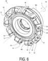
- FIG. 6 is a schematic perspective view of the cutting tool 46 illustrated in FIG. 5 viewed at a different angle.
- the cutting tool 46 is a tool used for machining the workpiece W (see FIG. 7 ) and rotatable about a rotation axis RS.
- the cutting tool 46 may include a holder 48 attached to a main spindle of a processing machine such as a milling machine.
- the holder 48 may have a cylindrical shape extending from a first end 48a to a second end 48b along the rotation axis RS.
- Examples of the material of the holder 48 include metals such as stainless steel, carbon steel, cast iron, and an aluminum alloy.
- a plurality of pockets 50 may be located at intervals in a peripheral direction on the outer peripheral surface of the holder 48.
- the plurality of pockets 50 may be located at equal intervals in the peripheral direction or at unequal intervals in the peripheral direction.
- the number of pockets 50 may be one.
- the cutting tool 46 may include the cutting insert 10 located in each of the pockets 50 of the holder 48.
- the cutting insert 10 may be located only in a selected one or more of the pockets 50 in the holder 48.
- the cutting insert 10 may be fixed to the pocket 50 of the holder 48 by a fixing screw 52 inserted in the mounting hole 18.
- the cutting insert 10 may be fixed to the pocket 50 of the holder 48 by a clamp member. If machining is performed by the upper cutting edge 20, the lower surface 14 may be used as a seating surface for attachment to the holder 48 (see FIG. 3 ). If machining is performed by the lower cutting edge 22, the upper surface 12 may be used as a seating surface (see FIG. 3 ).
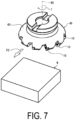
- FIGs. 7 to 9 are schematic views illustrating the method for manufacturing the machined product according to the embodiment of the present disclosure.
- the method for manufacturing the machined product according to the embodiment of the present disclosure is a method for manufacturing a machined product M, which is the workpiece W after machined, and includes a first step, a second step, and a third step.
- the first step is a step of rotating the cutting tool 46.
- the second step is a step of bringing the cutting tool 46, which is rotating, into contact with the workpiece W.
- the third step is a step of separating the cutting tool 46 from the workpiece W.
- examples of the material of the workpiece W include aluminum alloy, stainless steel, carbon steel, alloy steel, cast iron, and non-ferrous metal.
- the cutting tool 46 is moved toward the workpiece W in the direction of an arrow FD while being rotated in a rotation direction T. Then, the cutting insert 10 of the cutting tool 46, which is rotating, is moved in the direction of the arrow FD while being brought into contact with the workpiece W. Thus, machining of the workpiece W is performed by the cutting tool 46, and a machined surface Wf is formed on the workpiece as in the example illustrated in FIG. 9 .
- the cutting tool 46 is further moved in the direction of the arrow FD to be separated from the workpiece W. This completes the machining of the workpiece W and enables the machined product M, which is the workpiece W after the machining, to be manufactured. Since the cutting tool 46 has excellent cutting capabilities because of the above reasons, the machined product M having excellent machining accuracy can be manufactured.
- the cutting insert 10 of the cutting tool 46 simply has to be repeatedly brought into contact with a different portion of the workpiece W while the cutting tool 46 is being rotated.
- the cutting tool 46 is brought close to the workpiece W in the embodiment of the present disclosure, the cutting tool 46 only needs to be brought relatively close to the workpiece W. Accordingly, for example, the workpiece W may be brought close to the cutting tool 46. In this respect, the same procedure is performed in separating the cutting tool 46 from the workpiece W.
- the invention has been described above based on the drawings and embodiments.
- the invention according to the present disclosure is not limited to the above-described embodiment.
- the embodiment of the invention according to the present disclosure can be modified in various ways within the scope illustrated in the present disclosure, and embodiments obtained by appropriately combining the disclosed technical means are also included in the technical scope of the invention according to the present disclosure.
- a person skilled in the art can easily make various variations or modifications based on the present disclosure. Note that these variations or modifications are included within the scope of the present disclosure.
Landscapes
- Engineering & Computer Science (AREA)
- Mechanical Engineering (AREA)
- Milling Processes (AREA)
Abstract
Description
- The present disclosure relates to a cutting insert, a cutting tool, and a method for manufacturing a machined product.
- An example of a cutting tool is a so-called rotary tool. Rotary tools include an end mill and a milling tool.
- A cutting insert disclosed in
Patent Document 1 is known as a cutting insert applied to a cutting tool. The cutting insert described inPatent Document 1 is a so-called double-sided insert having cutting edges on an upper surface side and a lower surface side. The cutting edges inPatent Document 1 have a minor cutting edge (so-called flat cutting edge) for finish machining. The minor cutting edge has a protruding curved shape protruding upward in a side view.Patent Document 1 illustrates, as specific shapes of the minor cutting edge, an arc shape having a constant curvature and a protruding curved shape having a curvature gradually decreasing toward both ends in the side view. - Patent Document 1:
WO 2013/077443 - A cutting insert according to an aspect of the present disclosure includes: an upper surface; a lower surface located on an opposite side of the upper surface; a lateral surface connected to the upper surface and the lower surface; a upper cutting edge located on an intersection between the upper surface and the lateral surface; and a lower cutting edge located on an intersection between the lower surface and the lateral surface. The upper surface includes a first corner, a first side connected to the first corner, and a second side connected to the first corner on an opposite side of the first side. The upper cutting edge includes a main cutting edge located on the first side and having a linear shape in a top view, a minor cutting edge located on the second side and having a linear shape in the top view, and a connection edge located on the first corner, connected to the main cutting edge and the minor cutting edge, and having a protruding shape (protruding curved shape) protruding outward in the top view. The minor cutting edge has a protruding curved shape protruding upward in a side view and includes a first portion including an apex portion protruding most upward in the minor cutting edge, a second portion located between the first portion and the connection edge, and a third portion located between the second portion and the connection edge. Each of the second portion and the third portion comes close to the lower surface with distance from the first portion. In the side view, a radius of curvature of the second portion is larger than a radius of curvature of the first portion and a radius of curvature of the third portion.
- A cutting tool includes: a holder having a cylindrical shape extending from a first end to a second end along a rotation axis and including a pocket located on a side of the first end; and the cutting insert according to an aspect of the present disclosure located in the pocket.
- A method for manufacturing a machined product according to an aspect of the present disclosure includes: rotating the cutting tool according to an aspect of the present disclosure; bringing the cutting tool rotating into contact with a workpiece; and separating the cutting tool from the workpiece.
-
-
FIG. 1 is a schematic perspective view of a cutting insert according to an embodiment of the present disclosure. -
FIG. 2 is a schematic plan view of the cutting insert illustrated inFIG. 1 . -
FIG. 3 is a schematic side view of the cutting insert illustrated inFIG. 1 . -
FIG. 4 is an enlarged view of a part IV inFIG. 3 . -
FIG. 5 is a schematic perspective view of a cutting tool according to an embodiment of the present disclosure. -
FIG. 6 is a schematic perspective view of the cutting tool illustrated inFIG. 5 viewed at a different angle. -
FIG. 7 is a schematic view illustrating a method for manufacturing a machined product according to an embodiment of the present disclosure. -
FIG. 8 is a schematic view illustrating the method for manufacturing the machined product according to an embodiment of the present disclosure. -
FIG. 9 is a schematic view illustrating the method for manufacturing the machined product according to an embodiment of the present disclosure. - When a double-sided insert such as the cutting insert described in
Patent Document 1 is attached to a holder of a cutting tool, the axial rake of the cutting insert needs to be set to a negative value. Therefore, when the minor cutting edge has the shape illustrated inPatent Document 1, a region of the minor cutting edge that can be used as a flat cutting edge is limited, and finish machining may not be sufficiently performed on a workpiece. As a result, it is desired to improve surface accuracy (surface roughness) of the machined surface of the workpiece. - The present disclosure can improve the surface accuracy of the machined surface of the workpiece.
- A cutting insert, a cutting tool, and a method for manufacturing a machined product according to an embodiment of the present disclosure will be described below in detail with reference to the drawings. However, each of the drawings, which will be referred to below, is a simplified representation of only components necessary for description of the embodiment, for convenience of description. Accordingly, the cutting insert and the cutting tool according to an embodiment of the present disclosure may be provided with an optional component that is not illustrated in each of the referred drawings. The dimensions of the components in the drawings do not faithfully represent the actual dimensions of the components, the dimension ratios of the members, or the like.
- In the present disclosure, the insert central axis refers to a virtual axis passing through the center of the upper surface of the cutting insert and the center of the lower surface of the cutting insert. The term "inward direction" or "inner side" refers to a direction toward or a side closer to the insert central axis in the cutting insert. The term "outward direction" or "outer side" refers to a direction or a side away from the insert central axis in the cutting insert. The term "orthogonal" is not limited to being strictly orthogonal and means that an error of approximately ± 5 degrees is allowed. The term "parallel" is not limited to being strictly parallel and means that an error of about ± 5 degrees is allowed.
- A cutting insert 10 according to an embodiment of the present disclosure will be described with reference to
FIGs. 1 to 4 .FIG. 1 is a schematic perspective view of thecutting insert 10 according to the embodiment of the present disclosure.FIG. 2 is a schematic plan view of thecutting insert 10 illustrated inFIG. 1 .FIG. 3 is a schematic side view of thecutting insert 10 illustrated inFIG. 1 . Note thatFIG. 3 is a side view from the direction in which a second side described below is viewed from the front.FIG. 4 is an enlarged view of a part IV inFIG. 3 . - The
cutting insert 10 according to the embodiment of the present disclosure is a component of a cutting tool used for machining of a workpiece W (seeFIG. 7 ) made of a metal material or the like. Examples of the machining of the workpiece W include shoulder machining, grooving, R machining, and profiling. - As in the examples illustrated in
FIGs. 1 to 3 , thecutting insert 10 may include anupper surface 12 and alower surface 14 located on the opposite side of theupper surface 12. Each of theupper surface 12 and thelower surface 14 may have a polygonal shape, for example, an octagonal shape. In other words, thecutting insert 10 may have a polygonal plate shape, for example, an octagonal plate shape. Each of theupper surface 12 and thelower surface 14 may have a polygonal shape, for example, a triangular shape, a quadrangular shape, or the like other than the octagonal shape. In other words, thecutting insert 10 may have a polygonal plate shape, for example, a triangular plate shape, a quadrangular plate shape, or the like other than the octagonal plate shape. The polygonal shape is not limited strictly to a shape of a polygon. - As in the example illustrated in
FIG. 2 , each of theupper surface 12 and thelower surface 14 may have a rotationally symmetrical shape at a constant angle with respect to an insert central axis CS. Theupper surface 12 and thelower surface 14 may be shaped such that the front and back sides are reversed and symmetrical. In other words, thecutting insert 10 may have a rotationally symmetrical shape at a constant angle with respect to the insert central axis CS or may be shaped such that the front and back sides are reversed and symmetrical. - As in the examples illustrated in
FIG. 1 andFIG. 3 , thecutting insert 10 may include a plurality oflateral surfaces 16 located between theupper surface 12 and thelower surface 14. Thelateral surface 16 may be connected to theupper surface 12 and thelower surface 14. The lateral surfaces 16 may function as flank faces and may be parallel to the insert central axis CS. The cuttinginsert 10 is a so-called negative type cutting insert having a clearance angle of 0 degrees. - The cutting
insert 10 may include a mountinghole 18 penetrated from theupper surface 12 to thelower surface 14 as in the examples illustrated inFIGs. 1 to 3 . One opening of the mountinghole 18 may be located in a central portion of theupper surface 12, and the other opening of the mountinghole 18 may be located in a central portion of thelower surface 14. The central axis of the mountinghole 18 may coincide with the insert central axis CS. - As in the examples illustrated in
FIG. 1 andFIG. 2 , the cuttinginsert 10 may include aupper cutting edge 20 and alower cutting edge 22. Theupper cutting edge 20 may be located on an intersection between theupper surface 12 and thelateral surface 16. Thelower cutting edge 22 may be located on an intersection between thelower surface 14 and thelateral surface 16. In other words, the cuttinginsert 10 may be a double-sided insert provided with theupper cutting edge 20 and thelower cutting edge 22. Theupper cutting edge 20 may be located on the entire intersection between theupper surface 12 and thelateral surface 16 or may be located on part of the intersection between thereof. Thelower cutting edge 22 may be located on the entire intersection between thelower surface 14 and thelateral surface 16 or may be located on part of the intersection between thereof. - As in the example illustrated in
FIG. 2 , theupper surface 12 formed in a polygonal shape may include afirst corner 24 as one of a plurality of corners and asecond corner 26 as one other of a plurality of corners. Each of thefirst corner 24 and thesecond corner 26 may have a protruding curved shape protruding in an outward direction in a top view. - As in the examples illustrated in
FIG. 1 andFIG. 2 , theupper surface 12 may include afirst side 28 connected to thefirst corner 24 and asecond side 30 connected to thefirst corner 24 on the opposite side of thefirst side 28. Thesecond corner 26 may be connected to thesecond side 30 on the opposite side of thefirst corner 24. Thefirst side 28 may have a linear shape in the top view or may come close to thelower surface 14 with distance from thefirst corner 24 in a side view. Thesecond side 30 may have a linear shape in the top view. - In the top view, the
first side 28 and thesecond side 30 are not limited to the linear shape, and may have, for example, a gently protruding curved shape protruding in an outward direction. Here, "having a gently protruding curved shape" means having a radius of curvature larger than radii of curvature of thefirst corner 24 and thesecond corner 26 that have a protruding curved shape. - In a case, the
upper surface 12 has a rotationally symmetrical shape at a certain angle about the insert central axis CS, theupper surface 12 may have a plurality of thefirst corners 24 and a plurality of thesecond corners 26 as in the example illustrated inFIG. 2 . In this case, the plurality offirst corners 24 and the plurality ofsecond corners 26 may be alternately located along the peripheral direction of theupper surface 12. - The
upper surface 12 may also include a plurality of thefirst sides 28 and a plurality of the second sides 30. In a case, theupper surface 12 includes the plurality offirst corners 24, the plurality ofsecond corners 26, the plurality offirst sides 28, and the plurality ofsecond sides 30, the evaluation described below may be performed by focusing on portions extracted one by one from these portions such that the aforementioned positional relationship is provided. - As in the examples illustrated in
FIGs. 1 and2 , theupper surface 12 may include aland portion 32 located at the peripheral edge portion thereof, and theland portion 32 may be connected to theupper cutting edge 20. Theland portion 32 may function to enhance edge strength of theupper cutting edge 20. Theland portion 32 may be a portion that is adjacent to theupper cutting edge 20 and is indicated by a straight line in a cross-section orthogonal to theupper cutting edge 20 in the top view. - The
upper surface 12 may also include arake surface 34 located on the inner side of theland portion 32, and therake surface 34 may be connected to theland portion 32. Therake surface 34 may be inclined with respect to theland portion 32 and may come close to thelower surface 14 with distance from theland portion 32. - As in the examples illustrated in
FIG. 1 andFIG. 2 , theupper surface 12 may include abottom surface 36 located on the inner side of therake surface 34, and thebottom surface 36 may be connected to therake surface 34. Thebottom surface 36 may surround the opening of the mountinghole 18, and may be orthogonal to the insert central axis CS. - As illustrated in the examples illustrated in
FIGs. 1 to 3 , theupper cutting edge 20 may include amain cutting edge 38 located on thefirst side 28. Themain cutting edge 38 is a portion that can function as a main cutting edge in machining the workpiece W. Themain cutting edge 38 may be located over the entirety of thefirst side 28 or may be located over a portion of thefirst side 28. Themain cutting edge 38 may have a linear shape in the top view. - As in the examples illustrated in
FIGs. 1 to 4 , theupper cutting edge 20 may include aminor cutting edge 40 located on thesecond side 30. Theminor cutting edge 40 may function as a flat cutting edge for finishing the machined surface of the workpiece W. Theminor cutting edge 40 may be located over the entirety of thesecond side 30 or may be located over a portion of thesecond side 30. Theminor cutting edge 40 may have a linear shape in the top view. - As in the examples illustrated in
FIGs. 1 to 3 , theupper cutting edge 20 may include a first connection edge (connection edge) 42 located on thefirst corner 24, and thefirst connection edge 42 may be connected to themain cutting edge 38 and theminor cutting edge 40. Thefirst connection edge 42 may have a protruding curved shape protruding outward in the top view. Theupper cutting edge 20 may also include asecond connection edge 44 located on thesecond corner 26, and thesecond connection edge 44 may be connected to theminor cutting edge 40. Thesecond connection edge 44 may have a protruding curved shape protruding outward in the top view. - As in the example illustrated in
FIG. 4 , theminor cutting edge 40 may have a protruding curved shape protruding upward in the side view. Theminor cutting edge 40 may include afirst portion 40a including anapex portion 40t protruding most upward in theminor cutting edge 40, asecond portion 40b located between thefirst portion 40a and thefirst connection edge 42, and athird portion 40c located between thesecond portion 40b and thefirst connection edge 42. - As in the example illustrated in
FIG. 4 , in the side view, a length Lb of thesecond portion 40b of theminor cutting edge 40 may be longer than a length La of thefirst portion 40a and a length Lc of thethird portion 40c. The length of thethird portion 40c of theminor cutting edge 40 may be greater than the length of thefirst portion 40a. Each of thesecond portion 40b and thethird portion 40c of theminor cutting edge 40 may come close to thelower surface 14 with distance from thefirst portion 40a. - Note that the aforementioned "length La" means the width of the
first portion 40a in the direction orthogonal to the insert central axis CS in a side view of theinsert 10. Similarly, the aforementioned "length Lb" means the width of thesecond portion 40b in the direction orthogonal to the insert central axis CS in a side view of theinsert 10, and the aforementioned "length Lc" means the width of thethird portion 40c in the direction orthogonal to the insert central axis CS in a side view of theinsert 10. - As in the example illustrated in
FIG. 4 , in the side view, a radius of curvature Rb of thesecond portion 40b of theminor cutting edge 40 may be larger than a radius of curvature Ra of thefirst portion 40a and a radius of curvature Rc of thethird portion 40c. In other words, in the side view, the radius of curvature of thesecond portion 40b of theminor cutting edge 40 may be smaller than the radius of curvature of thefirst portion 40a and the radius of curvature of thethird portion 40c. In the side view, the radius of curvature Rc of thethird portion 40c of theminor cutting edge 40 may be larger than the radius of curvature Ra of thefirst portion 40a. In other words, in the side view, the radius of curvature of thethird portion 40c of theminor cutting edge 40 may be smaller than the radius of curvature of thefirst portion 40a. A distance D1 from theapex portion 40t of theminor cutting edge 40 to thesecond corner 26 may be shorter than a distance D2 from theapex portion 40t to thesecond portion 40b. InFIG. 4 , the radius of curvature Ra of thefirst portion 40a, the radius of curvature Rb of thesecond portion 40b, and the radius of curvature Rc of thethird portion 40c of theminor cutting edge 40 are schematically illustrated. - As in the example illustrated in
FIG. 4 , aboundary 12e between thesecond side 30 and thefirst corner 24 may be located closer to thelower surface 14 than aboundary 12p between thesecond side 30 and thesecond corner 26. Thefirst corner 24 may include afirst connection region 24a connected to thesecond side 30, and thefirst connection region 24a may have a recessed curved shape recessed downward in the side view. Thesecond corner 26 may include asecond connection region 26a connected to thesecond side 30, and thesecond connection region 26a may have a protruding curved shape protruding upward in the side view. - The positions of the
boundary 12e and theboundary 12p may be specified by a top surface view of the cuttinginsert 10. For example, if thefirst corner 24 and thesecond corner 26 have a protruding curved shape and thesecond side 30 has a linear shape in the top view, a virtual straight line along thesecond side 30 is set, and portions away from the virtual straight line may be regarded as theboundary 12e and theboundary 12p. If thefirst corner 24 and thesecond corner 26 have a protruding curved shape and thesecond side 30 has a gentle protruding curved shape in the top view, a virtual arc along thesecond side 30 is set, and portions away from the virtual arc may be regarded as theboundary 12e and theboundary 12p. - As in the examples illustrated in
FIGs. 1 to 3 , if theupper surface 12 and thelower surface 14 are shaped such that the front and back sides are reversed and symmetrical, thelower surface 14 may include portions corresponding to thefirst corner 24, thesecond corner 26, thefirst side 28, thesecond side 30, theland portion 32, and therake surface 34 of theupper surface 12. The configurations of the portions of thelower surface 14, which correspond to thefirst corner 24, thesecond corner 26, thefirst side 28, thesecond side 30, theland portion 32, and therake surface 34 may be the same as and/or similar to the configurations of thefirst corner 24, thesecond corner 26, thefirst side 28, thesecond side 30, theland portion 32, and therake surface 34 of theupper surface 12 except that the positional relationship in the vertical direction is reversed. - As in the examples illustrated in
FIGs. 1 to 3 , if theupper surface 12 and thelower surface 14 are shaped such that the front and back sides are reversed and symmetrical, thelower cutting edge 22 may include portions corresponding to themain cutting edge 38, theminor cutting edge 40, thefirst connection edge 42, and thesecond connection edge 44 of theupper cutting edge 20. The configurations of the portions of thelower cutting edge 22, which correspond to themain cutting edge 38, theminor cutting edge 40, thefirst connection edge 42, and thesecond connection edge 44 may be the same as and/or similar to the configurations of themain cutting edge 38, theminor cutting edge 40, thefirst connection edge 42, and thesecond connection edge 44 of theupper cutting edge 20 except that the positional relationship in the vertical direction is reversed. - An example of the material of the cutting
insert 10 includes a cemented carbide alloy or a cermet. Examples of the composition of the cemented carbide alloy include WC-Co produced by adding a cobalt (Co) powder to tungsten carbide (WC) and sintering the mixture, WC-TiC-Co formed by adding titanium carbide (TiC) to WC-Co, or WC-TiC-TaC-Co formed by adding tantalum carbide (TaC) to WC-TiC-Co. The cermet is a sintered composite material obtained by combining a metal with a ceramic component and specific examples thereof include titanium compounds in which a titanium compound such as titanium carbide (TiC) or titanium nitride (TiN) is the main component. - The surface of the cutting
insert 10 may be coated with a coating film using a chemical vapor deposition (CVD) method or a physical vapor deposition (PVD) method. Examples of the composition of the coating film include titanium carbide (TiC), titanium nitride (TiN), titanium carbonitride (TiCN), and alumina (Al2O3). - As in the example illustrated in
FIG. 4 , theminor cutting edge 40 has a protruding curved shape protruding upward in the side view. Each of thesecond portion 40b and thethird portion 40c of theminor cutting edge 40 comes close to thelower surface 14 with distance from thefirst portion 40a. The radius of curvature Rb of thesecond portion 40b of theminor cutting edge 40 is larger than the radius of curvature Ra of thefirst portion 40a and the radius of curvature Rc of thethird portion 40c. - In this case, the
second portion 40b which is a gently curved portion can be disposed on the center side of theminor cutting edge 40, and thefirst portion 40a and thethird portion 40c which are steepish curved portions can be disposed on both end sides of theminor cutting edge 40. Therefore, even if the axial rake angle of the cuttinginsert 10 is set to be negative, a wide region from thefirst portion 40a to thethird portion 40c of theminor cutting edge 40 can be used as a flat cutting edge. - This allows the example of the embodiment of the present disclosure to improve surface accuracy (surface roughness) of the machined surface of the workpiece. In particular, since the
first portion 40a including theapex portion 40t is a steepish curved portion, biting of theminor cutting edge 40 into the workpiece W is improved, and the surface accuracy of the machined surface of the workpiece W can be sufficiently improved. - Of the
first portion 40a to thethird portion 40c of theminor cutting edge 40, thethird portion 40c located closest to thefirst connection edge 42 is a steepish curved portion. Therefore, the example of the embodiment of the present disclosure can improve subsequent biting of the cuttinginsert 10 into the workpiece W during machining and reduce the occurrence of so-called tear by having the thickness of chips. - If the length of the
second portion 40b of theminor cutting edge 40 is greater than the length of thefirst portion 40a and the length of thethird portion 40c, the gentle portion of theminor cutting edge 40 is longer, and thus the surface accuracy of the machined surface of the workpiece W can be further improved. - If the
first connection region 24a of thefirst corner 24 has a recessed curved shape and thesecond connection region 26a of thesecond corner 26 has a protruding curved shape, the length of thesecond portion 40b of theminor cutting edge 40 can be sufficiently long. This allows the example of the embodiment of the present disclosure can further improve the surface accuracy of the machined surface of the workpiece W. - If the length of the
third portion 40c of theminor cutting edge 40 is greater than the length of thefirst portion 40a, thethird portion 40c as a gentle portion next to thefirst portion 40a of theminor cutting edge 40 can be long next to the first portion 30a. This allows the example of the embodiment of the present disclosure can further improve the surface accuracy of the machined surface of the workpiece W. - If the radius of curvature Rc of the
third portion 40c of theminor cutting edge 40 is larger than the radius of curvature Ra of thefirst portion 40a, stress concentration in thethird portion 40c to which a large cutting load tends to be applied compared to thefirst portion 40a can be reduced. This allows the example of the embodiment of the present disclosure can improve the durability of the cuttinginsert 10. - If the distance D1 from the
apex portion 40t of theminor cutting edge 40 to thesecond corner 26 is shorter than the distance D2 from theapex portion 40t to thesecond portion 40b, the flank face of thelateral surface 16, which is connected to thesecond corner 26 is unlikely to come into contact with the machined surface of the workpiece W. This allows the example of the embodiment of the present disclosure can improve the durability of the cuttinginsert 10. - If the
boundary 12e between thesecond side 30 and thefirst corner 24 is closer to thelower surface 14 than theboundary 12p between thesecond side 30 and thesecond corner 26, themain cutting edge 38 and theminor cutting edge 40 can be gradually brought into contact with the workpiece W from themain cutting edge 38 to theminor cutting edge 40, allowing a rapid increase in cutting resistance to be suppressed. This allows the example of the embodiment of the present disclosure can improve the durability of the cuttinginsert 10. - A cutting
tool 46 according to the embodiment of the present disclosure will be described with reference toFIG. 5 andFIG. 6 .FIG. 5 is a schematic perspective view of thecutting tool 46 according to the embodiment of the present disclosure.FIG. 6 is a schematic perspective view of thecutting tool 46 illustrated inFIG. 5 viewed at a different angle. - As illustrated in the examples in
FIG. 5 andFIG. 6 , the cuttingtool 46 according to the embodiment of the present disclosure is a tool used for machining the workpiece W (seeFIG. 7 ) and rotatable about a rotation axis RS. The cuttingtool 46 may include aholder 48 attached to a main spindle of a processing machine such as a milling machine. Theholder 48 may have a cylindrical shape extending from afirst end 48a to asecond end 48b along the rotation axis RS. Examples of the material of theholder 48 include metals such as stainless steel, carbon steel, cast iron, and an aluminum alloy. A plurality ofpockets 50 may be located at intervals in a peripheral direction on the outer peripheral surface of theholder 48. The plurality ofpockets 50 may be located at equal intervals in the peripheral direction or at unequal intervals in the peripheral direction. The number ofpockets 50 may be one. - As in the examples illustrated in
FIG. 5 andFIG. 6 , the cuttingtool 46 may include the cuttinginsert 10 located in each of thepockets 50 of theholder 48. The cuttinginsert 10 may be located only in a selected one or more of thepockets 50 in theholder 48. The cuttinginsert 10 may be fixed to thepocket 50 of theholder 48 by a fixingscrew 52 inserted in the mountinghole 18. The cuttinginsert 10 may be fixed to thepocket 50 of theholder 48 by a clamp member. If machining is performed by theupper cutting edge 20, thelower surface 14 may be used as a seating surface for attachment to the holder 48 (seeFIG. 3 ). If machining is performed by thelower cutting edge 22, theupper surface 12 may be used as a seating surface (seeFIG. 3 ). - A method for manufacturing the machined product according to the embodiment of the present disclosure will be described with reference to
FIGs. 7 to 9. FIGs. 7 to 9 are schematic views illustrating the method for manufacturing the machined product according to the embodiment of the present disclosure. - As in the examples illustrated in
FIGs. 7 to 9 , the method for manufacturing the machined product according to the embodiment of the present disclosure is a method for manufacturing a machined product M, which is the workpiece W after machined, and includes a first step, a second step, and a third step. The first step is a step of rotating thecutting tool 46. The second step is a step of bringing thecutting tool 46, which is rotating, into contact with the workpiece W. The third step is a step of separating thecutting tool 46 from the workpiece W. Here, examples of the material of the workpiece W include aluminum alloy, stainless steel, carbon steel, alloy steel, cast iron, and non-ferrous metal. The specific content of the method for manufacturing the machined product according to the embodiment of the present disclosure is as follows. - As in the examples illustrated in
FIG. 7 andFIG. 8 , the cuttingtool 46 is moved toward the workpiece W in the direction of an arrow FD while being rotated in a rotation direction T. Then, the cuttinginsert 10 of thecutting tool 46, which is rotating, is moved in the direction of the arrow FD while being brought into contact with the workpiece W. Thus, machining of the workpiece W is performed by the cuttingtool 46, and a machined surface Wf is formed on the workpiece as in the example illustrated inFIG. 9 . - Subsequently, as in the example illustrated in
FIG. 9 , the cuttingtool 46 is further moved in the direction of the arrow FD to be separated from the workpiece W. This completes the machining of the workpiece W and enables the machined product M, which is the workpiece W after the machining, to be manufactured. Since thecutting tool 46 has excellent cutting capabilities because of the above reasons, the machined product M having excellent machining accuracy can be manufactured. - If the machining is continued, the cutting
insert 10 of thecutting tool 46 simply has to be repeatedly brought into contact with a different portion of the workpiece W while thecutting tool 46 is being rotated. Although thecutting tool 46 is brought close to the workpiece W in the embodiment of the present disclosure, the cuttingtool 46 only needs to be brought relatively close to the workpiece W. Accordingly, for example, the workpiece W may be brought close to thecutting tool 46. In this respect, the same procedure is performed in separating thecutting tool 46 from the workpiece W. - In the present disclosure, the invention has been described above based on the drawings and embodiments. However, the invention according to the present disclosure is not limited to the above-described embodiment. In other words, the embodiment of the invention according to the present disclosure can be modified in various ways within the scope illustrated in the present disclosure, and embodiments obtained by appropriately combining the disclosed technical means are also included in the technical scope of the invention according to the present disclosure. In other words, a person skilled in the art can easily make various variations or modifications based on the present disclosure. Note that these variations or modifications are included within the scope of the present disclosure.
-
- 10 Cutting insert
- 12 Upper surface
- 12e Boundary between second side and first corner
- 12p Boundary between second side and second corner
- 14 Lower surface
- 16 Lateral surface
- 18 Mounting hole
- 20 Upper cutting edge
- 22 Lower cutting edge
- 24 First corner
- 24a First connection region
- 26 Second corner
- 26a Second connection region
- 28 First side
- 30 Second side
- 32 Land portion
- 34 Rake surface
- 36 Bottom surface
- 38 Main cutting edge
- 40 Minor cutting edge
- 40a First portion
- 40b Second portion
- 40c Third portion
- 40t Apex portion
- 42 First connection edge
- 44 Second connection edge
- 46 Cutting tool
- 50 Pocket
- 52 Fixing screw
- CS Insert central axis
- RS Rotation axis
Claims (9)
- A cutting insert, comprising:an upper surface;a lower surface located on an opposite side of the upper surface;a lateral surface connected to the upper surface and the lower surface;a upper cutting edge located on an intersection between the upper surface and the lateral surface; anda lower cutting edge located on an intersection between the lower surface and the lateral surface, whereinthe upper surface comprisesa first corner,a first side connected to the first corner, anda second side connected to the first corner on an opposite side of the first side, the upper cutting edge comprisesa main cutting edge located on the first side and having a linear shape in a top view,a minor cutting edge located on the second side and having a linear shape in the top view, anda connection edge located on the first corner, connected to the main cutting edge and the minor cutting edge, and having a protruding curved shape protruding outward in the top view,the minor cutting edge has a protruding curved shape protruding upward in a side view and comprisesa first portion comprising an apex portion protruding most upward in the minor cutting edge,a second portion located between the first portion and the connection edge, anda third portion located between the second portion and the connection edge,each of the second portion and the third portion comes close to the lower surface with distance from the first portion, andin the side view, a radius of curvature of the second portion is larger than a radius of curvature of the first portion and a radius of curvature of the third portion.
- The cutting insert according to claim 1, wherein the radius of curvature of the third portion is larger than the radius of curvature of the first portion.
- The cutting insert according to claim 1 or 2, wherein a length of the second portion is greater than a length of the first portion and a length of the third portion.
- The cutting insert according to claim 3, wherein the length of the third portion is greater than the length of the first portion.
- The cutting insert according to any one of claims 1 to 4, whereinthe upper surface further comprises a second corner connected to the second side on an opposite side of the first corner, anda distance from the apex portion to the second corner is shorter than a distance from the apex portion to the second portion.
- The cutting insert according to claim 5, wherein a boundary between the second side and the first corner is closer to the lower surface than a boundary between the second side and the second corner is.
- The cutting insert according to claim 5 or 6, whereinthe first corner comprises a first connection region connected to the second side,the second corner comprises a second connection region connected to the second side, andin the side view, the first connection region has a recessed curved shape recessed downward, and the second connection region has a protruding curved shape protruding upward.
- A cutting tool, comprising:a holder having a cylindrical shape extending from a first end to a second end along a rotation axis and comprising a pocket located on a side of the first end; andthe cutting insert according to any one of claims 1 to 7 located in the pocket.
- A method for manufacturing a machined product, the method comprising:rotating the cutting tool according to claim 8;bringing the cutting tool rotating into contact with a workpiece; andseparating the cutting tool from the workpiece.
Applications Claiming Priority (2)
| Application Number | Priority Date | Filing Date | Title |
|---|---|---|---|
| JP2022040642 | 2022-03-15 | ||
| PCT/JP2023/008795 WO2023176618A1 (en) | 2022-03-15 | 2023-03-08 | Cutting insert, cutting tool, and method for manufacturing cut workpiece |
Publications (2)
| Publication Number | Publication Date |
|---|---|
| EP4494793A1 true EP4494793A1 (en) | 2025-01-22 |
| EP4494793A4 EP4494793A4 (en) | 2026-03-11 |
Family
ID=88023121
Family Applications (1)
| Application Number | Title | Priority Date | Filing Date |
|---|---|---|---|
| EP23770574.4A Pending EP4494793A4 (en) | 2022-03-15 | 2023-03-08 | CUTTING INSERT, CUTTING TOOL AND METHOD FOR MAKING A CUTTING TOOL |
Country Status (6)
| Country | Link |
|---|---|
| US (1) | US20250196235A1 (en) |
| EP (1) | EP4494793A4 (en) |
| JP (1) | JP7706641B2 (en) |
| KR (1) | KR20240146684A (en) |
| CN (1) | CN118871236A (en) |
| WO (1) | WO2023176618A1 (en) |
Family Cites Families (6)
| Publication number | Priority date | Publication date | Assignee | Title |
|---|---|---|---|---|
| AT12630U1 (en) | 2011-08-26 | 2012-09-15 | Ceratizit Austria Gmbh | DOUBLE-SIDED CUTTING INSERT FOR MILLING |
| CN103619518B (en) | 2011-11-25 | 2016-08-17 | 住友电工硬质合金株式会社 | Indexable cutting inserts for milling |
| US8708616B2 (en) * | 2012-07-06 | 2014-04-29 | Iscar, Ltd. | Rotary cutting tool and reversible cutting insert therefor |
| KR101515994B1 (en) * | 2014-04-22 | 2015-05-04 | 한국야금 주식회사 | Single-faced insert and tool holder for mounting the same |
| US10919095B2 (en) * | 2016-07-11 | 2021-02-16 | Kyocera Corporation | Cutting insert, cutting tool, and method of manufacturing machined product |
| WO2020045438A1 (en) | 2018-08-30 | 2020-03-05 | 三菱マテリアル株式会社 | Cutting insert and cutting edge replacement type cutting tool |
-
2023
- 2023-03-08 EP EP23770574.4A patent/EP4494793A4/en active Pending
- 2023-03-08 US US18/846,656 patent/US20250196235A1/en active Pending
- 2023-03-08 WO PCT/JP2023/008795 patent/WO2023176618A1/en not_active Ceased
- 2023-03-08 CN CN202380027355.7A patent/CN118871236A/en active Pending
- 2023-03-08 JP JP2024507799A patent/JP7706641B2/en active Active
- 2023-03-08 KR KR1020247030467A patent/KR20240146684A/en active Pending
Also Published As
| Publication number | Publication date |
|---|---|
| US20250196235A1 (en) | 2025-06-19 |
| JP7706641B2 (en) | 2025-07-11 |
| KR20240146684A (en) | 2024-10-08 |
| JPWO2023176618A1 (en) | 2023-09-21 |
| CN118871236A (en) | 2024-10-29 |
| WO2023176618A1 (en) | 2023-09-21 |
| EP4494793A4 (en) | 2026-03-11 |
Similar Documents
| Publication | Publication Date | Title |
|---|---|---|
| US12325078B2 (en) | Cutting insert, cutting tool, and method for manufacturing machined product | |
| US11027339B2 (en) | Cutting insert, cutting tool, and method of manufacturing machined product | |
| JP6470405B2 (en) | CUTTING INSERT, CUTTING TOOL, AND CUTTING PRODUCT MANUFACTURING METHOD USING THE SAME | |
| JP7488332B2 (en) | Method for manufacturing rotary tools and machined products | |
| US10413978B2 (en) | Cutting tool and method for manufacturing cut workpiece | |
| US20210016363A1 (en) | Cutting insert, cuttiing tool and method for manufacturing machined product | |
| US11440103B2 (en) | Cutting insert, cutting tool, and method for manufacturing machined product | |
| US20190061012A1 (en) | Insert, cutting tool, and method for manufacturing machined product | |
| JP6847230B2 (en) | Manufacturing method for cutting inserts, cutting tools and cutting products | |
| JP7281532B2 (en) | Turning tool and manufacturing method of machined product | |
| US20250196236A1 (en) | Cutting insert, cutting tool, and method for manufacturing machined product | |
| EP4494793A1 (en) | Cutting insert, cutting tool, and method for manufacturing cut workpiece | |
| JP7114733B2 (en) | Manufacturing method of cutting insert, cutting tool and cutting work | |
| US20260084221A1 (en) | Cutting insert, cutting tool, and method for manufacturing machined product | |
| EP4417350A1 (en) | Cutting insert, cutting tool, and method for manufacturing cut product | |
| JP7763261B2 (en) | Cutting insert, cutting tool, and method for manufacturing machined product | |
| KR102540681B1 (en) | Methods for manufacturing cutting inserts, cutting tools and cutting components | |
| WO2023228741A1 (en) | Cutting tool and method for producing cut workpiece | |
| JP2020069598A (en) | Cutting insert, cutting tool and manufacturing method for cutting work-piece | |
| JPWO2019022016A1 (en) | Manufacturing method of cutting insert, cutting tool, and machined product | |
| JP2012232351A (en) | Cutting insert, cutting tool, and method of cutting workpiece to be cut using the same | |
| JP7758646B2 (en) | Cutting tool and method for manufacturing machined product | |
| JP7344168B2 (en) | Manufacturing method for cutting inserts, cutting tools, and cut products | |
| JPWO2020066958A1 (en) | Manufacturing method for cutting inserts, cutting tools and cutting products | |
| WO2021241623A1 (en) | Cutting insert, cutting tool, and method for manufacturing cut workpiece |
Legal Events
| Date | Code | Title | Description |
|---|---|---|---|
| STAA | Information on the status of an ep patent application or granted ep patent |
Free format text: STATUS: THE INTERNATIONAL PUBLICATION HAS BEEN MADE |
|
| PUAI | Public reference made under article 153(3) epc to a published international application that has entered the european phase |
Free format text: ORIGINAL CODE: 0009012 |
|
| STAA | Information on the status of an ep patent application or granted ep patent |
Free format text: STATUS: REQUEST FOR EXAMINATION WAS MADE |
|
| 17P | Request for examination filed |
Effective date: 20240913 |
|
| AK | Designated contracting states |
Kind code of ref document: A1 Designated state(s): AL AT BE BG CH CY CZ DE DK EE ES FI FR GB GR HR HU IE IS IT LI LT LU LV MC ME MK MT NL NO PL PT RO RS SE SI SK SM TR |
|
| DAV | Request for validation of the european patent (deleted) | ||
| DAX | Request for extension of the european patent (deleted) | ||
| A4 | Supplementary search report drawn up and despatched |
Effective date: 20260210 |
|
| RIC1 | Information provided on ipc code assigned before grant |
Ipc: B23C 5/20 20060101AFI20260204BHEP Ipc: B23C 5/06 20060101ALI20260204BHEP |