EP4494784A1 - Verbundwerkstoff, verfahren zur herstellung des verbundwerkstoffs und form - Google Patents
Verbundwerkstoff, verfahren zur herstellung des verbundwerkstoffs und form Download PDFInfo
- Publication number
- EP4494784A1 EP4494784A1 EP23770408.5A EP23770408A EP4494784A1 EP 4494784 A1 EP4494784 A1 EP 4494784A1 EP 23770408 A EP23770408 A EP 23770408A EP 4494784 A1 EP4494784 A1 EP 4494784A1
- Authority
- EP
- European Patent Office
- Prior art keywords
- melting
- point
- point metal
- alloy
- composite material
- Prior art date
- Legal status (The legal status is an assumption and is not a legal conclusion. Google has not performed a legal analysis and makes no representation as to the accuracy of the status listed.)
- Pending
Links
Images


Classifications
-
- B—PERFORMING OPERATIONS; TRANSPORTING
- B22—CASTING; POWDER METALLURGY
- B22C—FOUNDRY MOULDING
- B22C9/00—Moulds or cores; Moulding processes
- B22C9/06—Permanent moulds for shaped castings
- B22C9/061—Materials which make up the mould
-
- B—PERFORMING OPERATIONS; TRANSPORTING
- B22—CASTING; POWDER METALLURGY
- B22F—WORKING METALLIC POWDER; MANUFACTURE OF ARTICLES FROM METALLIC POWDER; MAKING METALLIC POWDER; APPARATUS OR DEVICES SPECIALLY ADAPTED FOR METALLIC POWDER
- B22F1/00—Metallic powder; Treatment of metallic powder, e.g. to facilitate working or to improve properties
- B22F1/06—Metallic powder characterised by the shape of the particles
-
- B—PERFORMING OPERATIONS; TRANSPORTING
- B22—CASTING; POWDER METALLURGY
- B22F—WORKING METALLIC POWDER; MANUFACTURE OF ARTICLES FROM METALLIC POWDER; MAKING METALLIC POWDER; APPARATUS OR DEVICES SPECIALLY ADAPTED FOR METALLIC POWDER
- B22F10/00—Additive manufacturing of workpieces or articles from metallic powder
- B22F10/20—Direct sintering or melting
- B22F10/25—Direct deposition of metal particles, e.g. direct metal deposition [DMD] or laser engineered net shaping [LENS]
-
- B—PERFORMING OPERATIONS; TRANSPORTING
- B22—CASTING; POWDER METALLURGY
- B22F—WORKING METALLIC POWDER; MANUFACTURE OF ARTICLES FROM METALLIC POWDER; MAKING METALLIC POWDER; APPARATUS OR DEVICES SPECIALLY ADAPTED FOR METALLIC POWDER
- B22F5/00—Manufacture of workpieces or articles from metallic powder characterised by the special shape of the product
- B22F5/007—Manufacture of workpieces or articles from metallic powder characterised by the special shape of the product of moulds
-
- B—PERFORMING OPERATIONS; TRANSPORTING
- B22—CASTING; POWDER METALLURGY
- B22F—WORKING METALLIC POWDER; MANUFACTURE OF ARTICLES FROM METALLIC POWDER; MAKING METALLIC POWDER; APPARATUS OR DEVICES SPECIALLY ADAPTED FOR METALLIC POWDER
- B22F7/00—Manufacture of composite layers, workpieces, or articles, comprising metallic powder, by sintering the powder, with or without compacting wherein at least one part is obtained by sintering or compression
- B22F7/008—Manufacture of composite layers, workpieces, or articles, comprising metallic powder, by sintering the powder, with or without compacting wherein at least one part is obtained by sintering or compression characterised by the composition
-
- B—PERFORMING OPERATIONS; TRANSPORTING
- B22—CASTING; POWDER METALLURGY
- B22F—WORKING METALLIC POWDER; MANUFACTURE OF ARTICLES FROM METALLIC POWDER; MAKING METALLIC POWDER; APPARATUS OR DEVICES SPECIALLY ADAPTED FOR METALLIC POWDER
- B22F7/00—Manufacture of composite layers, workpieces, or articles, comprising metallic powder, by sintering the powder, with or without compacting wherein at least one part is obtained by sintering or compression
- B22F7/06—Manufacture of composite layers, workpieces, or articles, comprising metallic powder, by sintering the powder, with or without compacting wherein at least one part is obtained by sintering or compression of composite workpieces or articles from parts, e.g. to form tipped tools
- B22F7/062—Manufacture of composite layers, workpieces, or articles, comprising metallic powder, by sintering the powder, with or without compacting wherein at least one part is obtained by sintering or compression of composite workpieces or articles from parts, e.g. to form tipped tools involving the connection or repairing of preformed parts
-
- B—PERFORMING OPERATIONS; TRANSPORTING
- B23—MACHINE TOOLS; METAL-WORKING NOT OTHERWISE PROVIDED FOR
- B23K—SOLDERING OR UNSOLDERING; WELDING; CLADDING OR PLATING BY SOLDERING OR WELDING; CUTTING BY APPLYING HEAT LOCALLY, e.g. FLAME CUTTING; WORKING BY LASER BEAM
- B23K26/00—Working by laser beam, e.g. welding, cutting or boring
- B23K26/34—Laser welding for purposes other than joining
- B23K26/342—Build-up welding
-
- B—PERFORMING OPERATIONS; TRANSPORTING
- B33—ADDITIVE MANUFACTURING TECHNOLOGY
- B33Y—ADDITIVE MANUFACTURING, i.e. MANUFACTURING OF THREE-DIMENSIONAL [3D] OBJECTS BY ADDITIVE DEPOSITION, ADDITIVE AGGLOMERATION OR ADDITIVE LAYERING, e.g. BY 3D PRINTING, STEREOLITHOGRAPHY OR SELECTIVE LASER SINTERING
- B33Y70/00—Materials specially adapted for additive manufacturing
- B33Y70/10—Composites of different types of material, e.g. mixtures of ceramics and polymers or mixtures of metals and biomaterials
-
- C—CHEMISTRY; METALLURGY
- C22—METALLURGY; FERROUS OR NON-FERROUS ALLOYS; TREATMENT OF ALLOYS OR NON-FERROUS METALS
- C22C—ALLOYS
- C22C14/00—Alloys based on titanium
-
- C—CHEMISTRY; METALLURGY
- C22—METALLURGY; FERROUS OR NON-FERROUS ALLOYS; TREATMENT OF ALLOYS OR NON-FERROUS METALS
- C22C—ALLOYS
- C22C19/00—Alloys based on nickel or cobalt
- C22C19/03—Alloys based on nickel or cobalt based on nickel
- C22C19/05—Alloys based on nickel or cobalt based on nickel with chromium
- C22C19/051—Alloys based on nickel or cobalt based on nickel with chromium and Mo or W
- C22C19/055—Alloys based on nickel or cobalt based on nickel with chromium and Mo or W with the maximum Cr content being at least 20% but less than 30%
-
- C—CHEMISTRY; METALLURGY
- C22—METALLURGY; FERROUS OR NON-FERROUS ALLOYS; TREATMENT OF ALLOYS OR NON-FERROUS METALS
- C22C—ALLOYS
- C22C19/00—Alloys based on nickel or cobalt
- C22C19/03—Alloys based on nickel or cobalt based on nickel
- C22C19/05—Alloys based on nickel or cobalt based on nickel with chromium
- C22C19/051—Alloys based on nickel or cobalt based on nickel with chromium and Mo or W
- C22C19/056—Alloys based on nickel or cobalt based on nickel with chromium and Mo or W with the maximum Cr content being at least 10% but less than 20%
-
- C—CHEMISTRY; METALLURGY
- C22—METALLURGY; FERROUS OR NON-FERROUS ALLOYS; TREATMENT OF ALLOYS OR NON-FERROUS METALS
- C22C—ALLOYS
- C22C19/00—Alloys based on nickel or cobalt
- C22C19/03—Alloys based on nickel or cobalt based on nickel
- C22C19/05—Alloys based on nickel or cobalt based on nickel with chromium
- C22C19/051—Alloys based on nickel or cobalt based on nickel with chromium and Mo or W
- C22C19/057—Alloys based on nickel or cobalt based on nickel with chromium and Mo or W with the maximum Cr content being less 10%
-
- C—CHEMISTRY; METALLURGY
- C22—METALLURGY; FERROUS OR NON-FERROUS ALLOYS; TREATMENT OF ALLOYS OR NON-FERROUS METALS
- C22C—ALLOYS
- C22C19/00—Alloys based on nickel or cobalt
- C22C19/07—Alloys based on nickel or cobalt based on cobalt
-
- C—CHEMISTRY; METALLURGY
- C22—METALLURGY; FERROUS OR NON-FERROUS ALLOYS; TREATMENT OF ALLOYS OR NON-FERROUS METALS
- C22C—ALLOYS
- C22C38/00—Ferrous alloys, e.g. steel alloys
- C22C38/002—Ferrous alloys, e.g. steel alloys containing In, Mg, or other elements not provided for in one single group C22C38/001 - C22C38/60
-
- C—CHEMISTRY; METALLURGY
- C22—METALLURGY; FERROUS OR NON-FERROUS ALLOYS; TREATMENT OF ALLOYS OR NON-FERROUS METALS
- C22C—ALLOYS
- C22C38/00—Ferrous alloys, e.g. steel alloys
- C22C38/004—Very low carbon steels, i.e. having a carbon content of less than 0,01%
-
- C—CHEMISTRY; METALLURGY
- C22—METALLURGY; FERROUS OR NON-FERROUS ALLOYS; TREATMENT OF ALLOYS OR NON-FERROUS METALS
- C22C—ALLOYS
- C22C38/00—Ferrous alloys, e.g. steel alloys
- C22C38/02—Ferrous alloys, e.g. steel alloys containing silicon
-
- C—CHEMISTRY; METALLURGY
- C22—METALLURGY; FERROUS OR NON-FERROUS ALLOYS; TREATMENT OF ALLOYS OR NON-FERROUS METALS
- C22C—ALLOYS
- C22C38/00—Ferrous alloys, e.g. steel alloys
- C22C38/04—Ferrous alloys, e.g. steel alloys containing manganese
-
- C—CHEMISTRY; METALLURGY
- C22—METALLURGY; FERROUS OR NON-FERROUS ALLOYS; TREATMENT OF ALLOYS OR NON-FERROUS METALS
- C22C—ALLOYS
- C22C38/00—Ferrous alloys, e.g. steel alloys
- C22C38/06—Ferrous alloys, e.g. steel alloys containing aluminium
-
- C—CHEMISTRY; METALLURGY
- C22—METALLURGY; FERROUS OR NON-FERROUS ALLOYS; TREATMENT OF ALLOYS OR NON-FERROUS METALS
- C22C—ALLOYS
- C22C38/00—Ferrous alloys, e.g. steel alloys
- C22C38/10—Ferrous alloys, e.g. steel alloys containing cobalt
- C22C38/105—Ferrous alloys, e.g. steel alloys containing cobalt containing Co and Ni
-
- C—CHEMISTRY; METALLURGY
- C22—METALLURGY; FERROUS OR NON-FERROUS ALLOYS; TREATMENT OF ALLOYS OR NON-FERROUS METALS
- C22C—ALLOYS
- C22C38/00—Ferrous alloys, e.g. steel alloys
- C22C38/12—Ferrous alloys, e.g. steel alloys containing tungsten, tantalum, molybdenum, vanadium, or niobium
-
- C—CHEMISTRY; METALLURGY
- C22—METALLURGY; FERROUS OR NON-FERROUS ALLOYS; TREATMENT OF ALLOYS OR NON-FERROUS METALS
- C22C—ALLOYS
- C22C38/00—Ferrous alloys, e.g. steel alloys
- C22C38/14—Ferrous alloys, e.g. steel alloys containing titanium or zirconium
-
- C—CHEMISTRY; METALLURGY
- C22—METALLURGY; FERROUS OR NON-FERROUS ALLOYS; TREATMENT OF ALLOYS OR NON-FERROUS METALS
- C22C—ALLOYS
- C22C38/00—Ferrous alloys, e.g. steel alloys
- C22C38/18—Ferrous alloys, e.g. steel alloys containing chromium
- C22C38/22—Ferrous alloys, e.g. steel alloys containing chromium with molybdenum or tungsten
-
- C—CHEMISTRY; METALLURGY
- C22—METALLURGY; FERROUS OR NON-FERROUS ALLOYS; TREATMENT OF ALLOYS OR NON-FERROUS METALS
- C22C—ALLOYS
- C22C38/00—Ferrous alloys, e.g. steel alloys
- C22C38/18—Ferrous alloys, e.g. steel alloys containing chromium
- C22C38/24—Ferrous alloys, e.g. steel alloys containing chromium with vanadium
-
- C—CHEMISTRY; METALLURGY
- C23—COATING METALLIC MATERIAL; COATING MATERIAL WITH METALLIC MATERIAL; CHEMICAL SURFACE TREATMENT; DIFFUSION TREATMENT OF METALLIC MATERIAL; COATING BY VACUUM EVAPORATION, BY SPUTTERING, BY ION IMPLANTATION OR BY CHEMICAL VAPOUR DEPOSITION, IN GENERAL; INHIBITING CORROSION OF METALLIC MATERIAL OR INCRUSTATION IN GENERAL
- C23C—COATING METALLIC MATERIAL; COATING MATERIAL WITH METALLIC MATERIAL; SURFACE TREATMENT OF METALLIC MATERIAL BY DIFFUSION INTO THE SURFACE, BY CHEMICAL CONVERSION OR SUBSTITUTION; COATING BY VACUUM EVAPORATION, BY SPUTTERING, BY ION IMPLANTATION OR BY CHEMICAL VAPOUR DEPOSITION, IN GENERAL
- C23C8/00—Solid state diffusion of only non-metal elements into metallic material surfaces; Chemical surface treatment of metallic material by reaction of the surface with a reactive gas, leaving reaction products of surface material in the coating, e.g. conversion coatings, passivation of metals
- C23C8/02—Pretreatment of the material to be coated
-
- C—CHEMISTRY; METALLURGY
- C23—COATING METALLIC MATERIAL; COATING MATERIAL WITH METALLIC MATERIAL; CHEMICAL SURFACE TREATMENT; DIFFUSION TREATMENT OF METALLIC MATERIAL; COATING BY VACUUM EVAPORATION, BY SPUTTERING, BY ION IMPLANTATION OR BY CHEMICAL VAPOUR DEPOSITION, IN GENERAL; INHIBITING CORROSION OF METALLIC MATERIAL OR INCRUSTATION IN GENERAL
- C23C—COATING METALLIC MATERIAL; COATING MATERIAL WITH METALLIC MATERIAL; SURFACE TREATMENT OF METALLIC MATERIAL BY DIFFUSION INTO THE SURFACE, BY CHEMICAL CONVERSION OR SUBSTITUTION; COATING BY VACUUM EVAPORATION, BY SPUTTERING, BY ION IMPLANTATION OR BY CHEMICAL VAPOUR DEPOSITION, IN GENERAL
- C23C8/00—Solid state diffusion of only non-metal elements into metallic material surfaces; Chemical surface treatment of metallic material by reaction of the surface with a reactive gas, leaving reaction products of surface material in the coating, e.g. conversion coatings, passivation of metals
- C23C8/06—Solid state diffusion of only non-metal elements into metallic material surfaces; Chemical surface treatment of metallic material by reaction of the surface with a reactive gas, leaving reaction products of surface material in the coating, e.g. conversion coatings, passivation of metals using gases
- C23C8/08—Solid state diffusion of only non-metal elements into metallic material surfaces; Chemical surface treatment of metallic material by reaction of the surface with a reactive gas, leaving reaction products of surface material in the coating, e.g. conversion coatings, passivation of metals using gases only one element being applied
- C23C8/24—Nitriding
-
- C—CHEMISTRY; METALLURGY
- C23—COATING METALLIC MATERIAL; COATING MATERIAL WITH METALLIC MATERIAL; CHEMICAL SURFACE TREATMENT; DIFFUSION TREATMENT OF METALLIC MATERIAL; COATING BY VACUUM EVAPORATION, BY SPUTTERING, BY ION IMPLANTATION OR BY CHEMICAL VAPOUR DEPOSITION, IN GENERAL; INHIBITING CORROSION OF METALLIC MATERIAL OR INCRUSTATION IN GENERAL
- C23C—COATING METALLIC MATERIAL; COATING MATERIAL WITH METALLIC MATERIAL; SURFACE TREATMENT OF METALLIC MATERIAL BY DIFFUSION INTO THE SURFACE, BY CHEMICAL CONVERSION OR SUBSTITUTION; COATING BY VACUUM EVAPORATION, BY SPUTTERING, BY ION IMPLANTATION OR BY CHEMICAL VAPOUR DEPOSITION, IN GENERAL
- C23C8/00—Solid state diffusion of only non-metal elements into metallic material surfaces; Chemical surface treatment of metallic material by reaction of the surface with a reactive gas, leaving reaction products of surface material in the coating, e.g. conversion coatings, passivation of metals
- C23C8/06—Solid state diffusion of only non-metal elements into metallic material surfaces; Chemical surface treatment of metallic material by reaction of the surface with a reactive gas, leaving reaction products of surface material in the coating, e.g. conversion coatings, passivation of metals using gases
- C23C8/36—Solid state diffusion of only non-metal elements into metallic material surfaces; Chemical surface treatment of metallic material by reaction of the surface with a reactive gas, leaving reaction products of surface material in the coating, e.g. conversion coatings, passivation of metals using gases using ionised gases, e.g. ionitriding
-
- C—CHEMISTRY; METALLURGY
- C23—COATING METALLIC MATERIAL; COATING MATERIAL WITH METALLIC MATERIAL; CHEMICAL SURFACE TREATMENT; DIFFUSION TREATMENT OF METALLIC MATERIAL; COATING BY VACUUM EVAPORATION, BY SPUTTERING, BY ION IMPLANTATION OR BY CHEMICAL VAPOUR DEPOSITION, IN GENERAL; INHIBITING CORROSION OF METALLIC MATERIAL OR INCRUSTATION IN GENERAL
- C23C—COATING METALLIC MATERIAL; COATING MATERIAL WITH METALLIC MATERIAL; SURFACE TREATMENT OF METALLIC MATERIAL BY DIFFUSION INTO THE SURFACE, BY CHEMICAL CONVERSION OR SUBSTITUTION; COATING BY VACUUM EVAPORATION, BY SPUTTERING, BY ION IMPLANTATION OR BY CHEMICAL VAPOUR DEPOSITION, IN GENERAL
- C23C8/00—Solid state diffusion of only non-metal elements into metallic material surfaces; Chemical surface treatment of metallic material by reaction of the surface with a reactive gas, leaving reaction products of surface material in the coating, e.g. conversion coatings, passivation of metals
- C23C8/80—After-treatment
-
- B—PERFORMING OPERATIONS; TRANSPORTING
- B22—CASTING; POWDER METALLURGY
- B22F—WORKING METALLIC POWDER; MANUFACTURE OF ARTICLES FROM METALLIC POWDER; MAKING METALLIC POWDER; APPARATUS OR DEVICES SPECIALLY ADAPTED FOR METALLIC POWDER
- B22F1/00—Metallic powder; Treatment of metallic powder, e.g. to facilitate working or to improve properties
- B22F1/05—Metallic powder characterised by the size or surface area of the particles
-
- B—PERFORMING OPERATIONS; TRANSPORTING
- B22—CASTING; POWDER METALLURGY
- B22F—WORKING METALLIC POWDER; MANUFACTURE OF ARTICLES FROM METALLIC POWDER; MAKING METALLIC POWDER; APPARATUS OR DEVICES SPECIALLY ADAPTED FOR METALLIC POWDER
- B22F1/00—Metallic powder; Treatment of metallic powder, e.g. to facilitate working or to improve properties
- B22F1/06—Metallic powder characterised by the shape of the particles
- B22F1/065—Spherical particles
-
- B—PERFORMING OPERATIONS; TRANSPORTING
- B22—CASTING; POWDER METALLURGY
- B22F—WORKING METALLIC POWDER; MANUFACTURE OF ARTICLES FROM METALLIC POWDER; MAKING METALLIC POWDER; APPARATUS OR DEVICES SPECIALLY ADAPTED FOR METALLIC POWDER
- B22F10/00—Additive manufacturing of workpieces or articles from metallic powder
- B22F10/20—Direct sintering or melting
- B22F10/28—Powder bed fusion, e.g. selective laser melting [SLM] or electron beam melting [EBM]
-
- B—PERFORMING OPERATIONS; TRANSPORTING
- B22—CASTING; POWDER METALLURGY
- B22F—WORKING METALLIC POWDER; MANUFACTURE OF ARTICLES FROM METALLIC POWDER; MAKING METALLIC POWDER; APPARATUS OR DEVICES SPECIALLY ADAPTED FOR METALLIC POWDER
- B22F10/00—Additive manufacturing of workpieces or articles from metallic powder
- B22F10/60—Treatment of workpieces or articles after build-up
- B22F10/62—Treatment of workpieces or articles after build-up by chemical means
-
- B—PERFORMING OPERATIONS; TRANSPORTING
- B22—CASTING; POWDER METALLURGY
- B22F—WORKING METALLIC POWDER; MANUFACTURE OF ARTICLES FROM METALLIC POWDER; MAKING METALLIC POWDER; APPARATUS OR DEVICES SPECIALLY ADAPTED FOR METALLIC POWDER
- B22F2301/00—Metallic composition of the powder or its coating
- B22F2301/20—Refractory metals
-
- B—PERFORMING OPERATIONS; TRANSPORTING
- B23—MACHINE TOOLS; METAL-WORKING NOT OTHERWISE PROVIDED FOR
- B23K—SOLDERING OR UNSOLDERING; WELDING; CLADDING OR PLATING BY SOLDERING OR WELDING; CUTTING BY APPLYING HEAT LOCALLY, e.g. FLAME CUTTING; WORKING BY LASER BEAM
- B23K2101/00—Articles made by soldering, welding or cutting
- B23K2101/34—Coated articles ; Surface treated articles
- B23K2101/35—Surface treated articles
-
- B—PERFORMING OPERATIONS; TRANSPORTING
- B33—ADDITIVE MANUFACTURING TECHNOLOGY
- B33Y—ADDITIVE MANUFACTURING, i.e. MANUFACTURING OF THREE-DIMENSIONAL [3D] OBJECTS BY ADDITIVE DEPOSITION, ADDITIVE AGGLOMERATION OR ADDITIVE LAYERING, e.g. BY 3D PRINTING, STEREOLITHOGRAPHY OR SELECTIVE LASER SINTERING
- B33Y10/00—Processes of additive manufacturing
-
- B—PERFORMING OPERATIONS; TRANSPORTING
- B33—ADDITIVE MANUFACTURING TECHNOLOGY
- B33Y—ADDITIVE MANUFACTURING, i.e. MANUFACTURING OF THREE-DIMENSIONAL [3D] OBJECTS BY ADDITIVE DEPOSITION, ADDITIVE AGGLOMERATION OR ADDITIVE LAYERING, e.g. BY 3D PRINTING, STEREOLITHOGRAPHY OR SELECTIVE LASER SINTERING
- B33Y40/00—Auxiliary operations or equipment, e.g. for material handling
- B33Y40/20—Post-treatment, e.g. curing, coating or polishing
Definitions
- the present invention relates to a composite material, a method for producing a composite material, and a mold using such composite material. More particularly, the present invention relates to, for example, a composite material preferably used for a mold, such as a casting mold used to cast an aluminum alloy, a method for producing a composite material, and a mold.
- a metal material having heat resistance such as JIS (Japanese Industrial Standards) SKD61
- JIS Japanese Industrial Standards
- SKD61 a metal material having heat resistance
- structures such as low-pressure casting, gravity casting, die casting, and other molds for aluminum alloys are used in a hot environment, damage or deformation may occur.
- dissolution loss and galling are known.
- a structure suffers from damage or deformation, a damaged or deformed site is repaired by overlaying a repairing material thereon.
- a repairing material is preferably an alloy with heat resistant properties, such as a high melting point and dissolution loss resistance.
- Patent Literature 1 JP Patent Publication (Kohyo) No. H01-502680 A
- the alloy disclosed in Patent Literature 1 has a high melting point and excellent creep strength; that is, it has heat resistance.
- a high-melting-point metal such as the alloy disclosed in Patent Literature 1
- production is often performed by sintering as disclosed in Patent Literature 1. While sintering facilitates production of the entire structure with the use of a single type of a metal, sintering is not suitable for production of a structure with the use of different types of metals in combination for the following reasons. That is, thermal stress cracking may occur because of differences in thermal expansion coefficients among different types of metals.
- the structure consisting of a high-melting-point metal is not practical in terms of a production cost and usability because the material is very expensive and has a very high specific gravity.
- the objects of the present invention are to provide a composite material that is durable when used in a hot environment and contributes to cost reduction, a method for easily producing such composite material, and a mold using such composite material.
- the composite material according to the present invention comprises an overlaid part (an padding part) comprising high-melting-point metal in at least a part on the surface of a low-melting-point alloy member having a melting point of 1600°C or lower, wherein the overlaid part comprising high-melting-point metal comprises high-melting-point metal particles comprising high-melting-point metal elements having a melting point of 2400°C or higher scattered therein and 40% or more of the high-melting-point metal particles has a roundness (circularity) of 0.7 or higher.
- the method for producing the composite material according to the present invention comprises a step of forming an overlaid part comprising high-melting-point metal in which the high-melting-point metal particles are scattered by feeding starting powders comprising the high-melting-point metal particles comprising high-melting-point metal elements having a melting point of 2400°C or higher with a roundness of 0.7 or higher to the surface of the low-melting-point alloy member while applying an energy to the surface of a low-melting-point alloy member having a melting point of 1600°C or lower to melt the low-melting-point alloy member.
- the mold according to the present invention is a mold using the composite material described above.
- the composite material according to the present invention comprises, in a part thereof, an overlaid part comprising high-melting-point metal comprising high-melting-point metal elements in the form of particles.
- the composite material can exert durability when used in a hot environment and it can contribute to cost reduction.
- a mold that is easily produced and suitable for use in a hot environment can be provided.
- the preposition "to" is used herein to include numerical values before and after the preposition as the lower limit and the upper limit.
- the upper or lower limit within a numerical range may be substituted with another upper or lower limit demonstrated in phases.
- the upper or lower limit within a numerical range provided herein may be substituted with a value provided in the examples.
- a material When a material is selected from among materials exemplified below, a single material may be selected or a plurality of materials may be selected in combination within a scope consistent with the present disclosure. Alternatively, materials other than the materials exemplified below may be selected within a scope consistent with the present disclosure.
- a composite material comprises an overlaid part comprising high-melting-point metal in at least a part on the surface of a low-melting-point alloy member having a melting point of 1600°C or lower, wherein the overlaid part comprising high-melting-point metal comprises high-melting-point metal particles comprising high-melting-point metal elements having a melting point of 2400°C or higher scattered therein, and 40% or more of the high-melting-point metal particles has a roundness of 0.7 or higher.
- the "overlaid part comprising high-melting-point metal” comprises high-melting-point metal particles comprising high-melting-point metal elements that account for, for example, 90% by mass or more thereof scattered therein. This does not indicate that the melting point of the overlaid part comprising high-melting-point metal is high.
- a low-melting-point alloy member is equivalent to, for example, a mold substrate.
- the composite material has, for example, an overlaid part comprising high-melting-point metal in which a large quantity of high-melting-point metal elements are comprised in high-melting-point metal particles with a high roundness in at least a part on the surface of the mold substrate. Accordingly, it is not necessary to produce the entire structure of a structure, such as a mold, with the use of a high-melting-point metal, and it is possible to selectively form a site where damage or deformation is likely to occur with the use of high-melting-point metals.
- a low-melting-point alloy member is not particularly limited, provided that it comprises an alloy having a melting point of 1600°C or lower (hereafter, it may be abbreviated as a "low-melting-point alloy").
- a member comprising a low-melting-point alloy with a melting point that is equivalent to or higher than the preheating temperature described below (300°C to 700°C) is preferable.
- a preferable example of a low-melting-point alloy member is a member comprising at least one type of a low-melting-point alloy selected from among a Fe-based alloy, a Ni-based alloy, a Co-based alloy, a Ti-based alloy, a Cr-based alloy, and a high-entropy alloy.
- Such low-melting-point alloys are easily produced as alloys having a melting point of 1600°C or lower.
- the energy such as the arc, laser, or electron beam energy (hereafter, it is referred to as the "thermal energy"
- a molten pool is easily prepared.
- a member comprising a Fe-based alloy is particularly preferable as a low-melting-point alloy member.
- a Fe-based alloy is not particularly limited, provided that it comprises Fe.
- a Fe-based alloy comprises 50% by mass or more Fe and at least one element selected from among nickel (Ni), chromium (Cr), cobalt (Co), molybdenum (Mo), tungsten (W), niobium (Nb), aluminum (Al), titanium (Ti), zirconium (Zr), tantalum (Ta), vanadium (V), hafnium (Hf), manganese (Mn), silicon (Si), lanthanum (La), magnesium (Mg), carbon (C), and boron (B).
- the low-melting-point alloy member consists of a Fe-based alloy
- the low-melting-point alloy member comprises 50% by mass or more Fe, 18.0% by mass to 19.0% by mass Ni, 8.5% by mass to 9.5% by mass Co, 4.7% by mass to 5.2% by mass Mo, 0.05% by mass to 0.15% by mass Al, 0.5% by mass to 0.7% by mass Ti, 0.1% by mass or less Mn, 0.1% by mass or less Si, 0.01% by mass or less P and S, and 0.03% by mass or less C.
- a Ni-based alloy is not particularly limited, provided that it comprises Ni.
- a Ni-based alloy comprises 50% by mass or more Ni and at least one element selected from among chromium (Cr), cobalt (Co), molybdenum (Mo), tungsten (W), niobium (Nb), aluminum (Al), titanium (Ti), iron (Fe), zirconium (Zr), tantalum (Ta), vanadium (V), hafnium (Hf), manganese (Mn), silicon (Si), lanthanum (La), magnesium (Mg), carbon (C), and boron (B).
- the low-melting-point alloy member consists of a Ni-based alloy
- the low-melting-point alloy member comprises 50% by mass or more Ni, 8% by mass to 22% by mass Cr, 28.5% by mass or less Co, 14.5% by mass or less Mo, 12% by mass or less W, 5% by mass or less Nb, 6.1% by mass or less Al, 4.7% by mass or less Ti, 18.5% by mass or less Fe, 0.1% by mass or less Zr, 4% by mass or less Ta, 1.0% by mass or less V, 1.3% by mass or less Hf, 0.05% by mass to 0.7% by mass Mn, 0.5% by mass or less Si, 0.02% by mass or less La, 0.02% by mass or less Mg, 0.02% by mass to 0.2% by mass C, and 0.05% by mass or less B.
- a Co-based alloy is not particularly limited, provided that it comprises Co.
- a Co-based alloy comprises 50% by mass or more Co and at least one element selected from among Cr, Ni, W, Mo, V, Fe, Mn, Si, and C.
- the low-melting-point alloy member consists of a Co-based alloy, for example, the low-melting-point alloy member comprises 50% by mass or more Co, 30% by mass or less Cr, 22% by mass or less Ni, 15% by mass or less W, 4.25% by mass or less Mo, 1.7% by mass or less V, 50% by mass or less Fe, 2.0% by mass or less Mn, 1.0% by mass or less Si, and 1.1% by mass or less C.
- a Ti-based alloy is not particularly limited, provided that it comprises Ti.
- a Ti-based alloy comprises 50% by mass or more Ti and at least one element selected from among Fe, Cr, W, Mo, Nb, Al, Zr, Ta, V, Y, Sn, Cu, Mn, Si, C, N, O, and H.
- the low-melting-point alloy member consists of a Ti-based alloy, for example, the low-melting-point alloy member comprises 50% by mass or more Ti, 5.50% by mass to 6.75% by mass Al, 3.5% by mass to 4.5% by mass V, 0.3% by mass or less Fe, 0.08% by mass or less C, 0.2% by mass or less O, 0.05% by mass or less N, and 0.015% by mass or less H.
- a method for producing a low-melting-point alloy member is not particularly limited, and examples of methods include a casting method and an additive manufacturing method.
- the overlaid part comprising high-melting-point metal comprises high-melting-point metal particles comprising high-melting-point metal elements having a melting point of 2400°C or higher scattered therein, and the high-melting-point metal particles comprise, for example, 90% by mass or more high-melting-point metal elements having a melting point of 2400°C or higher.
- the content of particles with a relatively high roundness of 0.7 or higher is 40% or more.
- the fatigue strength and other properties of the overlaid part comprising high-melting-point metal are improved.
- the content of metal particles with a roundness of 0.7 or higher is less than 40%, in contrast, sufficient effects cannot be attained.
- the overlaid part comprising high-melting-point metal comprises the high-melting-point metal elements that account for 50% by mass to 95% by mass thereof.
- the overlaid part comprising high-melting-point metal comprises the high-melting-point metal elements that account for 50% by mass to 95% by mass thereof. This improves dissolution loss resistance and other performance. When the content of the high-melting-point metal elements is less than 50% by mass, sufficient effects cannot be attained.
- a roundness is measured in the manner described below, which is described in the examples below.
- a roundness is determined by obtaining an optical microscope image observed at 500 ⁇ magnification and digitizing tungsten particles and substances other than the tungsten particles in the optical microscope image by image processing using image analysis software "Azoukun ver. 2.5" (Asahi Kasei Engineering Corporation.) to calculate the roundness based on the area and the peripheral length of the tungsten particles in accordance with the equation (3) below.
- Roundness 4 ⁇ ⁇ ⁇ (the area of high-melting-point metal particles) / (the peripheral length of the high-melting-point metal particles) 2
- the optical microscope images obtained at two sites are analyzed in terms of a roundness of high-melting-point metal particles in each of the sites where the optical microscope images were obtained, the roundness and the number of particles obtained in one site are totalized with those obtained in another site, and the percentage of particles by roundness is determined.
- the composite material preferably has a depth of overlaying (the overlaid part) from the surface of the overlaid part (the padding part) comprising high-melting-point metal (i.e., a thickness of the overlaid part comprising high-melting-point metal) of 300 ⁇ m or more, more preferably 500 ⁇ m or more, and further preferably 600 ⁇ m or more.
- the depth of overlaying (the depth of the overlaid part) from the surface of the overlaid part comprising high-melting-point metal is the depth of the overlaid part comprising high-melting-point metal from the surface of the overlaid part comprising high-melting-point metal.
- Al dissolution loss may advance locally depending on the conditions of usage.
- the composite material preferably has the Rockwell hardness of 40 HRC or higher or the Vickers hardness of 300 Hv or higher in the overlaid part comprising high-melting-point metal, with the Vickers hardness of 400 Hv or higher being more preferable. Such material is preferable because remarkable effects of suppressing deformation at high temperature are attained.
- Figure 1 shows an image showing a melt-solidified structure of the overlaid part comprising high-melting-point metal according to an example of the composite material of the embodiment obtained by cutting the composite material on a plane perpendicular to the travel direction of the bead (an overlaid part comprising high-melting-point metal) to obtain a cross section, mirror-polishing the cross section, and observing the polished cross section.
- Figure 1 A shows the entire overlaid part comprising high-melting-point metal
- Figure 1 B shows high-melting-point metal particles of the overlaid part comprising high-melting-point metal.
- the overlaid part 1 comprising high-melting-point metal comprises high-melting-point metal particles 2 with a relatively high roundness, which is specifically a roundness of 0.7 or higher, scattered in the melt-solidified structure of the low-melting-point alloy in an amount of 40% or more, and the melt-solidified structure comprises the high-melting-point metal particles 2 and a binder phase 3 surrounding the high-melting-point metal particles 2.
- the high-melting-point metal particles 2 are not particularly limited, provided that such high-melting-point metal particles comprise high-melting-point metal elements having a melting point of 2400°C or higher that account for, for example, 90% by mass or more thereof.
- the high-melting-point metal particles 2 have body-centered cubic (BCC) structures and comprise high-melting-point metal elements, such as W (melting point: 3422°C), Ta (melting point: 3020°C), Mo (melting point: 2623°C), and Nb (melting point: 2469°C), that account for 90% by mass or more thereof.
- a binder phase 3 is, for example, a phase in which some of the high-melting-point metal elements comprised in the high-melting-point metal particles 2 is dissolved in a type of a low-melting-point alloy selected from among the Fe-based alloy, the Ni-based alloy, the Co-based alloy, the Ti-based alloy, the Cr-based alloy, and the high-entropy alloy, etc. described above.
- the binder phase 3 may be divided into two or three phases depending on the combination of a low-melting-point alloy and the high-melting-point metal particles 2, production conditions, and the like.
- the binder phase 3 is often divided into at least one of a solid-solution phase consisting of a face-centered-cubic (FCC) phase and a solid-solution phase consisting of a BCC phase and at least one intermetallic compound comprising high-melting-point metal elements (a high-melting-point metal element) comprised in the high-melting-point metal particles that accounts for 30% by mass or more thereof (hereafter, it may be abbreviated as an "intermetallic compound").
- the binder phase 3 comprises an intermetallic compound having a high melting point.
- the crystalline structure of the high-melting-point intermetallic compound varies depending on the combination of a low-melting-point alloy and the high-melting-point metal particles 2, for example, the crystalline structure may be the ⁇ phase (Fe 7 W 6 ) represented by the space group R-3m or the Laves C14 phase (Fe 2 W) represented by the space group P63/mmc.
- the binder phase 3 may have a dendritic structure characteristic of the melt-solidified structure. A dendritic structure is not observed in a sintered compact obtained by sintering, but it is observed in an overlaid part produced by additive manufacturing involving melt solidification.
- a solid solution phase is an FCC phase having toughness superior to that of the BCC phase, the overlaid part has higher toughness, and cracking is less likely to occur at the time of molding.
- the overlaid part comprising high-melting-point metal have the intermetallic compound and that the total area ratio of the high-melting-point metal particles and the intermetallic compound on the cross section of the overlaid part comprising high-melting-point metal be 20% or more.
- Both the high-melting-point metal particles and the intermetallic compound have high melting points, hardness, and chemical stability. If the total area ratio thereof is 20% or more, accordingly, the durability of the composite material is improved to a significant extent.
- high-melting-point metal particles do not substantially comprise other elements and thus have high thermal conductivity.
- the total area ratio of the high-melting-point metal particles and the intermetallic compound on the cross section of the overlaid part comprising high-melting-point metal refers to a percentage of an area thereof on the cross section of the overlaid part comprising high-melting-point metal (e.g., a cross section perpendicular to the extended direction of the overlaid part comprising high-melting-point metal extended).
- such total area ratio can be determined by cutting the overlaid part comprising high-melting-point metal to obtain a cross section, mirror-polishing the cross section, observing the cross section under a scanning electron microscope (SEM) to obtain a backscattered electron image, and subjecting the backscattered electron image to binary image processing.
- SEM scanning electron microscope
- the area ratio of high-melting-point metal particles can be determined by observing the optical microscope image.
- the high-melting-point metal particles are not particularly limited, provided that the content of high-melting-point metal elements having a melting point of 2400°C or higher is, for example, 90% by mass or more therein.
- particles comprising at least one type of a high-melting-point metal element selected from among W, Ta, Mo, and Nb are preferable, particles comprising at least one type of such high-melting-point metal element that accounts for 90% by mass or more thereof are more preferable, and particles comprising W that accounts for 90% by mass or more thereof are particularly preferable for the following reason. That is, thermal conductivity can be improved because of high thermal conductivity of W.
- the high-melting-point metal particles may comprise V and/or Cr, in addition to the high-melting-point metal element.
- the method for producing a composite material comprises a step of forming an overlaid part comprising high-melting-point metal in which at least some starting powders comprising the high-melting-point metal particles (which are referred to as "high-melting-point powders") are scattered in the form of approximately spherical shape (a roundness of 0.7 or higher) high-melting-point metal particles without being dissolved in the low-melting-point alloy by feeding starting powders having the spherical high-melting-point metal particles comprising the high-melting-point metal element having a melting point of 2400°C or higher to the surface of the low-melting-point alloy member while applying a thermal energy to the surface of a low-melting-point alloy member having a melting point of 1600°C or lower to melt the low-melting-point alloy member.
- the thermal energy is applied to at least a part on the surface of the low-melting-point alloy member to melt at least a part of the low-melting-point alloy member, starting powders comprising high-melting-point metal powders are simultaneously fed to the molten pool of it to melt the low-melting-point alloy and solidify the low-melting-point alloy.
- an overlaid part comprising high-melting-point metal in which high-melting-point metal particles comprising at least some of the high-melting-point metal powders are scattered without the at least some of the high-melting-point metal powders being dissolved in the low-melting-point alloy is formed.
- high-melting-point metal powders having the melting point that is relatively different from that of the low-melting-point alloy member.
- a larger difference in the melting points enables the high-melting-point metal powders to remain in the form of high-melting-point metal particles in the overlaid part comprising high-melting-point metal without being dissolved in the low-melting-point alloy.
- the high-melting-point metal particles are excellent in hardness, heat resistance, and thermal conductivity. Thus, heat resistance and thermal conductivity of the composite material can be improved.
- a metal element e.g., Fe
- High-melting-point metal powders are not particularly limited, provided that such powders comprise high-melting-point metal particles having a melting point of 2400°C or higher.
- High-melting-point metal powders may comprise one or more types of powders comprising high-melting-point metal. Examples of such high-melting-point metal powders include powders comprising at least one type of high-melting-point metal selected from among W, Ta, Mo, and Nb.
- Powders comprising at least one of such metals such as powders consisting of W, powders consisting of Ta, powders consisting of Mo, and powders consisting of Nb are preferable, with powders consisting of W being particularly preferable.
- Such high-melting-point metal powders can also be supplemented with powders comprising other metals. Examples thereof include high-melting-point metal powders supplemented with powders comprising V and/or Cr.
- a method for applying a thermal energy is not particularly limited, provided that it enables formation of an overlaid part.
- a thermal energy may be applied by means of a plasma arc, laser beam, or electron beam.
- a method of powder overlay welding described below is preferable.
- powders that further comprise low-melting-point alloy powders having a melting point of 1600°C or lower may be fed as the starting powders, in addition to the high-melting-point metal powders, in the step of forming the overlaid part comprising high-melting-point metal.
- high-melting-point metal powders are selectively overlaid, a melting point at a site of the member subjected to overlaying is elevated as the number of stacking of overlaid layers is increased. This makes molding difficult to be performed by overlaying, and the number of stacking performed by overlaying is limited to approximately 1 to 5.
- powders further comprising low-melting-point alloy powders are overlaid in addition to high-melting-point metal powders, an increase in a melting point at a site of the member subjected to overlaying can be suppressed even if the number of stacking is increased. Thus, 5 or more layers can be stacked by overlaying.
- Low-melting-point alloy powders are not particularly limited, provided that such powders comprise a low-melting-point alloy having a melting point of 1600°C or lower.
- Low-melting-point alloy powders may comprise one or more types of powders comprising a low-melting-point alloy.
- Such low-melting-point alloy powders preferably comprise, for example, one type of low-melting-point alloy selected from among an Fe-based alloy, an Ni-based alloy, a Co-based alloy, a Ti-based alloy, a Cr-based alloy, and a high-entropy alloy, and powders comprising the Fe-based alloy are particularly preferable.
- Such powders are preferable because the Fe-based alloy is small in cost, the Ni-based alloy is inferior to the Fe-based alloy in terms of resistance to Al dissolution loss, and the Co-based alloy and the Ti-based alloy are likely to generate brittle structures such as a regular BCC phase or an intermetallic compound when mixed with a mold material.
- the method for producing a composite material is preferably a method for forming the overlaid part comprising high-melting-point metal while preheating the low-melting-point alloy member to 300°C to 700°C in the step of forming the overlaid part comprising high-melting-point metal. Such method is preferable because cracking of the composite material can be suppressed.
- the method for producing a composite material according to another embodiment may further comprise, before the step of forming the overlaid part comprising high-melting-point metal, a step of forming a low-melting-point overlaid part by feeding starting powders comprising low-melting-point alloy powders having a melting point of 1600°C or lower to the surface of the low-melting-point alloy member while applying a thermal energy to the surface of the low-melting-point alloy member to melt the low-melting-point alloy.
- the low-melting-point overlaid part may be formed as a part of the low-melting-point alloy member.
- the overlaid part comprising high-melting-point metal is preferably formed on the surface of the low-melting-point overlaid part of the low-melting-point alloy member.
- the method for producing a composite material according to a modified example may further comprise a step of forming a low-melting-point overlaid part after the step of forming the overlaid part comprising high-melting-point metal.
- a thermal energy is applied to the surface of the overlaid part comprising high-melting-point metal to melt the overlaid part comprising high-melting-point metal, and the starting powders comprising the low-melting-point alloy powders are fed to the surface of the overlaid part comprising high-melting-point metal.
- the low-melting-point overlaid part is formed.
- the overlaid parts comprising high-melting-point metal and the low-melting-point overlaid parts are preferably stacked alternately on top of each other on the surface of the low-melting-point alloy member.
- Such method is preferable because an increase in the melting point in a site of the member subjected to overlaying can be suppressed even if the number of stacking is increased, and 5 or more layers can be stacked.
- the method for producing a composite material is preferably, for example, a method for forming the low-melting-point overlaid part while preheating the low-melting-point alloy member to 300°C to 700°C in the step of forming the low-melting-point overlaid part. Such method is preferable because cracking of the composite material can be suppressed.
- high-melting-point metal powders preferably have an enhanced sphericity.
- high-melting-point metal powders that have attained an enhanced sphericity by thermal plasma droplet refining (PDR) are preferable.
- PDR thermal plasma droplet refining
- Such powders are preferable because enhanced powder fluidity can further stabilize powder feeding.
- the average particle diameter of powders are not particularly limited, provided that such powders can be fed for powder overlaying, and the average particle diameter may be 1 ⁇ m to 200 ⁇ m to facilitate powder feeding.
- the average particle diameter is preferably 10 ⁇ m to 180, and more preferably 20 ⁇ m to 150 ⁇ m.
- High-melting-point metal powders are not limited to those selectively comprising powders comprising high-melting-point metal, and high-melting-point metal powders may be granulated powders prepared with the addition of a small amount of metals having low melting points, such as Ni, Co, or Fe, as binders to the powders comprising high-melting-point metal.
- a method for producing high-melting-point metal powders is not particularly limited.
- high-melting-point metal powders can be produced by the thermal plasma-droplet-refining (PDR) method, the water atomization method, the gas atomization method, or the jet atomization method.
- PDR thermal plasma-droplet-refining
- W water atomization method
- gas atomization method gas atomization method
- jet atomization method atomization method
- compounds such as oxides of starting materials may be reduced to produce powders.
- the gas atomization method involves the use of, for example, inert gas such as nitrogen or argon or high-pressure gas such as air as an atomizing medium. Powders obtained by the gas atomization method easily become spherical. Because a cooling rate by gas is smaller than a cooling rate by water, molten particles of droplets become spherical because of the surface tension before the molten particles are solidified.
- inert gas such as nitrogen or argon
- high-pressure gas such as air
- the jet atomization method involves the use of, for example, a combustion flame of kerosene as an atomizing medium.
- a high-temperature flame jet is sprayed onto a molten metal at a speed higher than the sonic speed, and the molten metal is accelerated and pulverized for a relatively long period of time to form powders. Powders obtained by the jet atomization method easily become spherical, and a further refined particle distribution can be achieved.
- Methods of overlaying of powders such as high-melting-point metal powders and low-melting-point alloy powders are not particularly limited, provided that an overlaid part, such as an overlaid part comprising high-melting-point metal or a low-melting-point overlaid part, can be formed on the surface of a member subjected to overlaying.
- Examples of methods that can be adopted include the method of plasma powder overlay welding and the method of laser powder overlay welding.
- the method of plasma powder overlay welding and the method of laser powder overlay welding can be types of additive manufacturing methods.
- the method of plasma powder overlay welding involves the use of a plasma as a heat source.
- welding is performed in an inert argon atmosphere. This enables formation of an overlaid part having a smooth surface and a small number of pores in its inside.
- LMD laser metal deposition
- an overlaid part may be formed while preheating the member subj ected to overlaying (e.g., a member of a mold) to 300°C to 700°C in accordance with a material or configuration of the member subjected to overlaying.
- preheating By performing preheating, deformation or cracking of an overlaid part caused by overlaying can be suppressed.
- a method of preheating is not particularly limited.
- preheating can be performed by means of high-frequency induction heating, a gas burner, an infrared electric heater, a heating furnace, or application of an electron beam or a laser.
- alloy powders produced by the method described above or a method other than the method described above can be used.
- the overlaid part such as the overlaid part comprising high-melting-point metal or the low-melting-point overlaid part in which the content, the type, and other properties of high-melting-point metal particles are varied in accordance with, for example, the likelihood of damage or deformation occurring in regions of a structure, such as a mold, can be formed in various regions on the surface of the member subjected to overlaying.
- an adequate overlaid part may be formed in an adequate region on the surface of the member subjected to overlaying (e.g., a plane of a casting mold that is in contact with a molten metal or a processed plane of a press or forging mold that is in contact with a processing material) in accordance with the likelihood of damage or deformation occurring in various regions of a mold, so that a structure, such as a high-performance mold, that is excellent in anti-dissolution loss can be obtained.
- overlaying e.g., a plane of a casting mold that is in contact with a molten metal or a processed plane of a press or forging mold that is in contact with a processing material
- the composite material may be entirely or partially subjected to surface hardening through diffusion such as nitriding or carburization, according to need.
- nitriding treatment examples include radical nitriding, gas nitriding, and plasma ion nitriding.
- nitriding is performed at high temperatures, disadvantageously, hardness of the overlaid part comprising high-melting-point metal or the low-melting-point alloy member may be lowered. Accordingly, nitriding is performed preferably at 600°C or lower, and more preferably at 550°C or lower. When nitriding is performed at excessively low temperatures, a nitrided layer is less likely to be formed. Thus, it is preferable that nitriding be performed at 400°C or higher.
- a composite material can be used for any application without particular limitation, provided that a composite material can be used for a structure for an intended use.
- a mold such as a casting mold is preferable as the application (the structure), a casting mold used for casting of an aluminum alloy, such as a low-pressure casting, gravity casting, or die casting mold, is more preferable, and a casting mold used for die casting of an aluminum alloy is particularly preferable.
- Such casting molds are preferable because remarkable effects, such as improved dissolution loss resistance, can be achieved.
- a casting mold for an aluminum alloy is not particularly limited. Examples thereof include a low-pressure casting mold used for molding aluminum wheels and a casting mold used for molding aluminum cylinder heads for engines.
- the composite material can be extensively used for structures other than a casting mold that are required to be resistant to high temperatures. For example, the composite material can be used for a bearing that may generate a frictional heat at a high-speed revolution.
- An application of the composite material may be a new structure, such as a casting mold, produced from a material or a repaired structure prepared by forming an overlaid part comprising high-melting-point metal in a site on the surface of a structure such as a casting mold where a damage or deformation has occurred (at least a part on the surface of the low-melting-point alloy member).
- the method for producing a composite material may be adopted for a method for producing a new structure such as a casting mold or a method for producing a repaired structure prepared by forming an overlaid part comprising high-melting-point metal in a site on the surface of a structure such as a casting mold where a damage or deformation has occurred.
- pure tungsten powders consisting of W high-melting-point metal powders
- W high-melting-point metal powders
- MMD laser metal deposition
- a composite material C1 was produced using spherical pure tungsten powders with the average particle diameter of 25 ⁇ m prepared by thermal plasma-droplet-refining (PDR).
- PDR thermal plasma-droplet-refining
- a composite material C2 was produced using grounded pure tungsten powders with a particle diameter of 53 ⁇ m.
- both the composite materials of Example 1 and Reference Example were subjected to a step of overlaying comprising applying a laser beam to melt the surface of the plate material of the Fe-based alloy and simultaneously feeding pure tungsten powders (starting powders) to the surface of the plate material M1 of the Fe-based alloy.
- a layer of the overlaid part comprising high-melting-point metal was formed.
- Lasertec 65-3D (DMG MORI CO., LTD.) was used as an apparatus for additive manufacturing. Conditions for powder overlaying were as described below.
- Example 1 and Reference Example were each cut on a plane perpendicular to the extended direction of a bead (the overlaid part comprising high-melting-point metal) to obtain a cross section, the cross section was mirror-polished, and the polished cross sections were observed under an optical microscope.
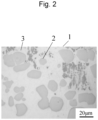
- Figure 1 B and Figure 2 each show an optical microscope image of Example 1 and an optical microscope image of Reference Example observed at 500 ⁇ magnification.
- scattered gray particles are observed in both Figure 1 B and Figure 2 .
- Such scattered particles are tungsten particles remaining undissolved. Accordingly, a roundness of tungsten particles (high-melting-point metal particles) and the Vickers hardness of the bead (the overlaid part comprising high-melting-point metal) were measured below.
- a roundness was determined by obtaining an optical microscope image observed at 500 ⁇ magnification and digitizing tungsten particles and substances other than the tungsten particles in the optical microscope image by image processing using image analysis software "Azoukun ver. 2.5" (Asahi Kasei Engineering Corporation.) to calculate the roundness based on the area and the peripheral length of the tungsten particles in accordance with the equation (3) below.
- Roundness 4 ⁇ ⁇ ⁇ (the area of high-melting-point metal particles) / (the peripheral length of the high-melting-point metal particles) 2
- the optical microscope images obtained at two sites were analyzed in terms of a roundness of high-melting-point metal particles in each of the sites where the optical microscope images had been obtained, the roundness and the number of particles obtained in one site were totalized with those obtained in another site, and the percentage of particles by roundness was determined.
- Table 2 shows the results of measurement of the roundness of the tungsten particles (high-melting-point metal particles) of Example 1 and Reference Example.
- Example 1 In the composite material of Example 1, the percentage of particles with the roundness of 0.7 to 1.0 was 62%. This indicates that the form of spherical tungsten particles is directly reflected. In the composite material of Reference Example, in contrast, the percentage of particles with the roundness of 0.7 to 1.0 was as low as 26%. The area ratio of tungsten particles of Example 1 was 32%, and it was substantially the same as that of Reference Example, which was 30%.
- Example 1 The depth of the overlaid part comprising high-melting-point metal from the surface of the plate material (the low-melting-point alloy member) of Example 1 was approximately 900 ⁇ m to 950 ⁇ m, and that of Reference Example was approximately 550 ⁇ m to 600 ⁇ m.
- Example 1 and Reference Example were subjected to measurement of the Vickers hardness (Hv1) of the overlaid part comprising high-melting-point metal and the Fe-based alloy part at room temperature. Specifically, a plane of the overlaid part comprising high-melting-point metal and that of the Fe-based alloy part were mirror-polished, and the hardness of the polished planes were measured. Conditions for measurement of hardness were as described below, measurement was performed 5 times, and the average of the 5 measured values was designated as the Vickers hardness.
- Hv1 Vickers hardness
- the composite material of Example 1 was found to have the Vickers hardness of 592 Hv in the Fe-based alloy part and the Vickers hardness of 402 Hv in the overlaid part comprising high-melting-point metal
- the composite material of Reference Example was found to have the Vickers hardness of 591 Hv in the Fe-based alloy part and the Vickers hardness of 354 Hv in the overlaid part comprising high-melting-point metal.
- Table 6 An example of a conventional alloy is DENSIMET 185 (Plansee SE, Austria; DENSIMET is a registered trademark of Plansee).
- the hardness of the overlaid part using such alloy is approximately 392 Hv.
- the composite material attained higher hardness because of the tungsten particles remained and scattered therein.
- the overlaid part is less likely to achieve hardness because it is significantly affected by a heat; however, both the composite materials of Example 1 and Reference Example may have achieved sufficient hardness as materials for repairing molds.
- the composite material of Example 1 comprising a larger quantity of tungsten particles with high roundness is more effective because of higher hardness.
- the plate material M2 of the Fe-based alloy as shown in Table 3 was prepared. Each numerical value indicates % by mass.
- the overlaid part comprising high-melting-point metal was observed under an optical microscope in the same manner as in Example 1.
- the plate material was soaked in a Nital solution composed of 3% nitric acid and 97% ethanol for approximately 10 seconds before observation.
- scattered tungsten particles 2 were observed in Example 2.
- the roundness of the tungsten particles and the Vickers hardness of the overlaid part comprising high-melting-point metal were measured in the same manner as in Example 1. The results are shown in Table 5 and Table 6.
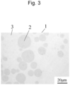
- the plate material M3 of the Ni-based alloy as shown in Table 4 was prepared. Each numerical value indicates % by mass.
- pure tungsten powders were fed to a part on the surface of the plate material M3 of the Ni-based alloy by laser metal deposition (LMD) to produce a composite material C5 comprising a layer of the overlaid part.
- LMD laser metal deposition
- the pure tungsten powders as used in Example 1 were used herein.
- the apparatus for additive manufacturing, the conditions for powder overlaying, and other conditions as used in Example 1 were employed herein.
- the overlaid part comprising high-melting-point metal was observed under an optical microscope in the same manner as in Example 1.
- Figure 4 scattered tungsten particles 2 were observed.
- the roundness of the tungsten particles and the Vickers hardness of the overlaid part comprising high-melting-point metal were measured in the same manner as in Example 1. The results are shown in Table 5 and Table 6.
- Table 5 shows the results of measurement of the roundness of the composite materials of Example 2 and Example 3.
- the percentage of the particles with the roundness of 0.7 or higher was found to be 40% or more. Since the composite material of Example 3 was an alloy comprising a large quantity of Ni, it is deduced that a large quantity of the laser input energy was consumed to melt the plate material and, as a consequence, the amount of the remaining tungsten particles was increased. The area ratio of tungsten particles was 24% in Example 2 and that was 14% in Example 3.
- the depth of the overlaid part comprising high-melting-point metal from the surface of the plate material of Example 2 was approximately 450 ⁇ m to 460 ⁇ m, and that of Example 3 was approximately 1100 ⁇ m to 1130 ⁇ m. Thus, the depth of the overlaid part was 300 ⁇ m or more in all of the composite materials of Examples 1 to 3.
- Table 6 shows the results of measurement of the Vickers hardness.
- the composite material of Example 2 was found to have the Vickers hardness of 465 Hv in the Fe-based alloy part and the Vickers hardness of 531 Hv in the overlaid part comprising high-melting-point metal
- the composite material of Example 3 was found to have the Vickers hardness of 208 Hv in the Ni-based alloy part and the Vickers hardness of 313 Hv in the overlaid part comprising high-melting-point metal. That is, both the overlaid parts of Example 2 and Example 3 were found to have higher hardness than the hardness of the overlaid part of an equivalent conventional alloy.
- Example 1 (Fe-base 1) Reference Example (Fe-base 1)
- Example 2 (Fe-base 2)
- Example 3 Ni-base) Composite material
- Low-melting-point alloy part (plate material) 592 591 465 208 Overlaid part comprising high-melting-point metal 402 354 531 313
- the composite material C1 of Example 1 was subjected to the ion-plasma nitriding treatment. Specifically, a part of the bead was cut with a wire cutter, and the sample was introduced into a plasma nitriding furnace with the inner furnace dimension of ⁇ 700 mm ⁇ 1200 mm (effective inner furnace dimension: ⁇ 600 mm ⁇ 600 mm). Before the nitriding treatment, the inside of the furnace was heated to 410°C in vacuum, the surface of the sample was subjected to gas etching at a gas rate of N 2 :H 2 : Ar of 6:91:3, and the nitriding treatment was then performed at 510°C for 10 hours.
- the surface hardness of the nitrided layer of the overlaid part comprising high-melting-point metal after the nitriding treatment was measured in the same manner at an indentation load of 25 g. As a result, the Vickers hardness was found to be 481 Hv. The surface hardness was improved as a result of the nitriding treatment.
Landscapes
- Chemical & Material Sciences (AREA)
- Engineering & Computer Science (AREA)
- Mechanical Engineering (AREA)
- Materials Engineering (AREA)
- Organic Chemistry (AREA)
- Metallurgy (AREA)
- Manufacturing & Machinery (AREA)
- Physics & Mathematics (AREA)
- Optics & Photonics (AREA)
- Composite Materials (AREA)
- Chemical Kinetics & Catalysis (AREA)
- Ceramic Engineering (AREA)
- Civil Engineering (AREA)
- Structural Engineering (AREA)
- Plasma & Fusion (AREA)
- Nanotechnology (AREA)
- Powder Metallurgy (AREA)
Applications Claiming Priority (2)
| Application Number | Priority Date | Filing Date | Title |
|---|---|---|---|
| JP2022042997 | 2022-03-17 | ||
| PCT/JP2023/007543 WO2023176450A1 (ja) | 2022-03-17 | 2023-03-01 | 複合材及び複合材の製造方法並びに金型 |
Publications (2)
| Publication Number | Publication Date |
|---|---|
| EP4494784A1 true EP4494784A1 (de) | 2025-01-22 |
| EP4494784A4 EP4494784A4 (de) | 2026-04-29 |
Family
ID=88023569
Family Applications (1)
| Application Number | Title | Priority Date | Filing Date |
|---|---|---|---|
| EP23770408.5A Pending EP4494784A4 (de) | 2022-03-17 | 2023-03-01 | Verbundwerkstoff, verfahren zur herstellung des verbundwerkstoffs und form |
Country Status (4)
| Country | Link |
|---|---|
| US (1) | US20240383032A1 (de) |
| EP (1) | EP4494784A4 (de) |
| JP (1) | JPWO2023176450A1 (de) |
| WO (1) | WO2023176450A1 (de) |
Families Citing this family (2)
| Publication number | Priority date | Publication date | Assignee | Title |
|---|---|---|---|---|
| CN118600358B (zh) * | 2024-08-07 | 2024-11-01 | 北京工业大学 | 低热导、高热流反射率、高耐蚀的高熵合金涂层及其制备方法和应用 |
| CN118910535B (zh) * | 2024-10-11 | 2024-12-31 | 株洲季元科技有限责任公司 | 柱塞或轴类工件的表面涂层及其制备方法和应用 |
Family Cites Families (7)
| Publication number | Priority date | Publication date | Assignee | Title |
|---|---|---|---|---|
| JPS5020936A (de) * | 1973-06-25 | 1975-03-05 | ||
| JPS62103355A (ja) * | 1985-10-28 | 1987-05-13 | Yoshikawa Kogyo Co Ltd | プレス用樹脂金型の製造方法 |
| AT386612B (de) | 1987-01-28 | 1988-09-26 | Plansee Metallwerk | Kriechfeste legierung aus hochschmelzendem metall und verfahren zu ihrer herstellung |
| JPH05331694A (ja) * | 1992-06-01 | 1993-12-14 | Kobe Steel Ltd | 機械構造用複合めっき非鉄金属材 |
| JP4596580B2 (ja) * | 1999-09-27 | 2010-12-08 | 三井金属鉱業株式会社 | マグネシウム合金の鋳造法及び鋳造品 |
| WO2016158687A1 (ja) * | 2015-03-31 | 2016-10-06 | 山陽特殊製鋼株式会社 | 球状粒子からなる金属粉末 |
| JP6738619B2 (ja) * | 2016-03-10 | 2020-08-12 | 株式会社フジミインコーポレーテッド | 溶射材およびその利用 |
-
2023
- 2023-03-01 EP EP23770408.5A patent/EP4494784A4/de active Pending
- 2023-03-01 JP JP2024507705A patent/JPWO2023176450A1/ja active Pending
- 2023-03-01 WO PCT/JP2023/007543 patent/WO2023176450A1/ja not_active Ceased
- 2023-03-01 US US18/688,119 patent/US20240383032A1/en active Pending
Also Published As
| Publication number | Publication date |
|---|---|
| WO2023176450A1 (ja) | 2023-09-21 |
| US20240383032A1 (en) | 2024-11-21 |
| JPWO2023176450A1 (de) | 2023-09-21 |
| EP4494784A4 (de) | 2026-04-29 |
Similar Documents
| Publication | Publication Date | Title |
|---|---|---|
| EP3787822B1 (de) | Ods-legierungspulver, verfahren zu seiner herstellung mittels plasmabehandlung und dessen verwendung | |
| EP4494784A1 (de) | Verbundwerkstoff, verfahren zur herstellung des verbundwerkstoffs und form | |
| US9211586B1 (en) | Non-faceted nanoparticle reinforced metal matrix composite and method of manufacturing the same | |
| CN110418688A (zh) | 高碳含量钴基合金 | |
| EP4048463A1 (de) | Bedruckbares pulvermaterial aus fecral zur additiven herstellung und additiv hergestellter gegenstand und verwendung davon | |
| US11883880B2 (en) | Alloy, alloy powder, alloy member, and composite member | |
| JP7018603B2 (ja) | クラッド層の製造方法 | |
| EP3950177B1 (de) | Legierung auf ni-basis, legierungspulver auf ni-basis, legierungsteil auf ni-basis und mit legierungsteil auf ni-basis ausgestattetes produkt | |
| TWI799782B (zh) | 鈷基合金構造體及其製造方法 | |
| US20220134428A1 (en) | Method for manufacturing cobalt-based alloy structure, and cobalt-based alloy structure obtained thereby | |
| EP4180549B1 (de) | Legierung auf eisenbasis zur schmelzeverfestigungs-formung und metallpulver | |
| EP4438203A1 (de) | Verbundwerkstoff, herstellungsverfahren für verbundwerkstoff und form | |
| Su et al. | Dense layer, microstructure, and mechanical performances of Ti–6Al–4V alloy prepared by metal injection molding | |
| US12209298B2 (en) | Ni—Cr—Mo-based alloy member, Ni—Cr—Mo-based alloy powder, and composite member | |
| EP3950992B1 (de) | Legierungszusammensetzung, verfahren zur herstellung einer legierungszusammensetzung und matrize | |
| EP4159883B1 (de) | Legierung auf fe-basis, metallpulver und deren verwendung für die schmelzverfestigungsformung | |
| WO2023037577A1 (ja) | サーメット複合材及びその製造方法、並びにサーメット工具 | |
| EP4506478A1 (de) | Legierung, legierungspulver, legierungselement und verbundelement | |
| JP7677529B2 (ja) | 積層造形体からなるNi-Cr合金部材、Ni-Cr合金部材の製造方法、およびNi-Cr合金部材を用いた製造物 | |
| Matos et al. | Evaluation of X22CrMoV12-1 alloy with vanadium carbide addition submitted to powder metallurgy | |
| Cong et al. | Comparison of microstructure and mechanical properties of ODS nickel-based alloy fabricated by laser powder bed fusion and spark plasma sintering | |
| CN121752374A (zh) | 增材制造用Ni基合金粉末及Ni基合金造型物的制造方法 | |
| CN118957357A (zh) | 钛基复合材料及其制备方法、3d打印方法 | |
| JP2022053869A (ja) | 合金組成物および合金組成物の製造方法、並びに金型 | |
| Im et al. | A New Strategy Addressing the Increasing Demand for Metal Additive Manufacturing Using an Economical Water-Atomized Iron Powder for Laser Powder Bed Fusion |
Legal Events
| Date | Code | Title | Description |
|---|---|---|---|
| STAA | Information on the status of an ep patent application or granted ep patent |
Free format text: STATUS: THE INTERNATIONAL PUBLICATION HAS BEEN MADE |
|
| PUAI | Public reference made under article 153(3) epc to a published international application that has entered the european phase |
Free format text: ORIGINAL CODE: 0009012 |
|
| STAA | Information on the status of an ep patent application or granted ep patent |
Free format text: STATUS: REQUEST FOR EXAMINATION WAS MADE |
|
| 17P | Request for examination filed |
Effective date: 20241017 |
|
| AK | Designated contracting states |
Kind code of ref document: A1 Designated state(s): AL AT BE BG CH CY CZ DE DK EE ES FI FR GB GR HR HU IE IS IT LI LT LU LV MC ME MK MT NL NO PL PT RO RS SE SI SK SM TR |
|
| DAV | Request for validation of the european patent (deleted) | ||
| DAX | Request for extension of the european patent (deleted) | ||
| REG | Reference to a national code |
Ref country code: DE Ref legal event code: R079 Free format text: PREVIOUS MAIN CLASS: B22F0005000000 Ipc: B22C0009060000 |