EP4494744A1 - Kohlendioxidabscheidungsverfahren und gasabsorptionssystem - Google Patents
Kohlendioxidabscheidungsverfahren und gasabsorptionssystem Download PDFInfo
- Publication number
- EP4494744A1 EP4494744A1 EP22951766.9A EP22951766A EP4494744A1 EP 4494744 A1 EP4494744 A1 EP 4494744A1 EP 22951766 A EP22951766 A EP 22951766A EP 4494744 A1 EP4494744 A1 EP 4494744A1
- Authority
- EP
- European Patent Office
- Prior art keywords
- temporary storage
- gas
- solution
- storage structure
- carbon dioxide
- Prior art date
- Legal status (The legal status is an assumption and is not a legal conclusion. Google has not performed a legal analysis and makes no representation as to the accuracy of the status listed.)
- Pending
Links
Images


Classifications
-
- B—PERFORMING OPERATIONS; TRANSPORTING
- B01—PHYSICAL OR CHEMICAL PROCESSES OR APPARATUS IN GENERAL
- B01D—SEPARATION
- B01D53/00—Separation of gases or vapours; Recovering vapours of volatile solvents from gases; Chemical or biological purification of waste gases, e.g. engine exhaust gases, smoke, fumes, flue gases, aerosols
- B01D53/14—Separation of gases or vapours; Recovering vapours of volatile solvents from gases; Chemical or biological purification of waste gases, e.g. engine exhaust gases, smoke, fumes, flue gases, aerosols by absorption
- B01D53/1456—Removing acid components
- B01D53/1475—Removing carbon dioxide
-
- B—PERFORMING OPERATIONS; TRANSPORTING
- B01—PHYSICAL OR CHEMICAL PROCESSES OR APPARATUS IN GENERAL
- B01D—SEPARATION
- B01D53/00—Separation of gases or vapours; Recovering vapours of volatile solvents from gases; Chemical or biological purification of waste gases, e.g. engine exhaust gases, smoke, fumes, flue gases, aerosols
- B01D53/14—Separation of gases or vapours; Recovering vapours of volatile solvents from gases; Chemical or biological purification of waste gases, e.g. engine exhaust gases, smoke, fumes, flue gases, aerosols by absorption
- B01D53/1412—Controlling the absorption process
-
- B—PERFORMING OPERATIONS; TRANSPORTING
- B01—PHYSICAL OR CHEMICAL PROCESSES OR APPARATUS IN GENERAL
- B01D—SEPARATION
- B01D53/00—Separation of gases or vapours; Recovering vapours of volatile solvents from gases; Chemical or biological purification of waste gases, e.g. engine exhaust gases, smoke, fumes, flue gases, aerosols
- B01D53/14—Separation of gases or vapours; Recovering vapours of volatile solvents from gases; Chemical or biological purification of waste gases, e.g. engine exhaust gases, smoke, fumes, flue gases, aerosols by absorption
- B01D53/1425—Regeneration of liquid absorbents
-
- B—PERFORMING OPERATIONS; TRANSPORTING
- B01—PHYSICAL OR CHEMICAL PROCESSES OR APPARATUS IN GENERAL
- B01D—SEPARATION
- B01D53/00—Separation of gases or vapours; Recovering vapours of volatile solvents from gases; Chemical or biological purification of waste gases, e.g. engine exhaust gases, smoke, fumes, flue gases, aerosols
- B01D53/14—Separation of gases or vapours; Recovering vapours of volatile solvents from gases; Chemical or biological purification of waste gases, e.g. engine exhaust gases, smoke, fumes, flue gases, aerosols by absorption
- B01D53/1493—Selection of liquid materials for use as absorbents
-
- B—PERFORMING OPERATIONS; TRANSPORTING
- B01—PHYSICAL OR CHEMICAL PROCESSES OR APPARATUS IN GENERAL
- B01D—SEPARATION
- B01D53/00—Separation of gases or vapours; Recovering vapours of volatile solvents from gases; Chemical or biological purification of waste gases, e.g. engine exhaust gases, smoke, fumes, flue gases, aerosols
- B01D53/14—Separation of gases or vapours; Recovering vapours of volatile solvents from gases; Chemical or biological purification of waste gases, e.g. engine exhaust gases, smoke, fumes, flue gases, aerosols by absorption
- B01D53/18—Absorbing units; Liquid distributors therefor
- B01D53/185—Liquid distributors
-
- B—PERFORMING OPERATIONS; TRANSPORTING
- B01—PHYSICAL OR CHEMICAL PROCESSES OR APPARATUS IN GENERAL
- B01D—SEPARATION
- B01D53/00—Separation of gases or vapours; Recovering vapours of volatile solvents from gases; Chemical or biological purification of waste gases, e.g. engine exhaust gases, smoke, fumes, flue gases, aerosols
- B01D53/34—Chemical or biological purification of waste gases
- B01D53/346—Controlling the process
-
- B—PERFORMING OPERATIONS; TRANSPORTING
- B01—PHYSICAL OR CHEMICAL PROCESSES OR APPARATUS IN GENERAL
- B01D—SEPARATION
- B01D53/00—Separation of gases or vapours; Recovering vapours of volatile solvents from gases; Chemical or biological purification of waste gases, e.g. engine exhaust gases, smoke, fumes, flue gases, aerosols
- B01D53/34—Chemical or biological purification of waste gases
- B01D53/46—Removing components of defined structure
- B01D53/62—Carbon oxides
-
- B—PERFORMING OPERATIONS; TRANSPORTING
- B01—PHYSICAL OR CHEMICAL PROCESSES OR APPARATUS IN GENERAL
- B01D—SEPARATION
- B01D53/00—Separation of gases or vapours; Recovering vapours of volatile solvents from gases; Chemical or biological purification of waste gases, e.g. engine exhaust gases, smoke, fumes, flue gases, aerosols
- B01D53/34—Chemical or biological purification of waste gases
- B01D53/74—General processes for purification of waste gases; Apparatus or devices specially adapted therefor
- B01D53/77—Liquid phase processes
- B01D53/78—Liquid phase processes with gas-liquid contact
-
- B—PERFORMING OPERATIONS; TRANSPORTING
- B01—PHYSICAL OR CHEMICAL PROCESSES OR APPARATUS IN GENERAL
- B01D—SEPARATION
- B01D53/00—Separation of gases or vapours; Recovering vapours of volatile solvents from gases; Chemical or biological purification of waste gases, e.g. engine exhaust gases, smoke, fumes, flue gases, aerosols
- B01D53/34—Chemical or biological purification of waste gases
- B01D53/96—Regeneration, reactivation or recycling of reactants
- B01D53/965—Regeneration, reactivation or recycling of reactants including an electrochemical process step
-
- C—CHEMISTRY; METALLURGY
- C25—ELECTROLYTIC OR ELECTROPHORETIC PROCESSES; APPARATUS THEREFOR
- C25B—ELECTROLYTIC OR ELECTROPHORETIC PROCESSES FOR THE PRODUCTION OF COMPOUNDS OR NON-METALS; APPARATUS THEREFOR
- C25B1/00—Electrolytic production of inorganic compounds or non-metals
- C25B1/01—Products
- C25B1/02—Hydrogen or oxygen
- C25B1/04—Hydrogen or oxygen by electrolysis of water
-
- F—MECHANICAL ENGINEERING; LIGHTING; HEATING; WEAPONS; BLASTING
- F03—MACHINES OR ENGINES FOR LIQUIDS; WIND, SPRING, OR WEIGHT MOTORS; PRODUCING MECHANICAL POWER OR A REACTIVE PROPULSIVE THRUST, NOT OTHERWISE PROVIDED FOR
- F03B—MACHINES OR ENGINES FOR LIQUIDS
- F03B7/00—Water wheels
-
- B—PERFORMING OPERATIONS; TRANSPORTING
- B01—PHYSICAL OR CHEMICAL PROCESSES OR APPARATUS IN GENERAL
- B01D—SEPARATION
- B01D2251/00—Reactants
- B01D2251/30—Alkali metal compounds
- B01D2251/304—Alkali metal compounds of sodium
-
- B—PERFORMING OPERATIONS; TRANSPORTING
- B01—PHYSICAL OR CHEMICAL PROCESSES OR APPARATUS IN GENERAL
- B01D—SEPARATION
- B01D2251/00—Reactants
- B01D2251/30—Alkali metal compounds
- B01D2251/306—Alkali metal compounds of potassium
-
- B—PERFORMING OPERATIONS; TRANSPORTING
- B01—PHYSICAL OR CHEMICAL PROCESSES OR APPARATUS IN GENERAL
- B01D—SEPARATION
- B01D2251/00—Reactants
- B01D2251/40—Alkaline earth metal or magnesium compounds
- B01D2251/404—Alkaline earth metal or magnesium compounds of calcium
-
- B—PERFORMING OPERATIONS; TRANSPORTING
- B01—PHYSICAL OR CHEMICAL PROCESSES OR APPARATUS IN GENERAL
- B01D—SEPARATION
- B01D2251/00—Reactants
- B01D2251/60—Inorganic bases or salts
- B01D2251/604—Hydroxides
-
- B—PERFORMING OPERATIONS; TRANSPORTING
- B01—PHYSICAL OR CHEMICAL PROCESSES OR APPARATUS IN GENERAL
- B01D—SEPARATION
- B01D2251/00—Reactants
- B01D2251/60—Inorganic bases or salts
- B01D2251/606—Carbonates
-
- B—PERFORMING OPERATIONS; TRANSPORTING
- B01—PHYSICAL OR CHEMICAL PROCESSES OR APPARATUS IN GENERAL
- B01D—SEPARATION
- B01D2252/00—Absorbents, i.e. solvents and liquid materials for gas absorption
- B01D2252/10—Inorganic absorbents
-
- B—PERFORMING OPERATIONS; TRANSPORTING
- B01—PHYSICAL OR CHEMICAL PROCESSES OR APPARATUS IN GENERAL
- B01D—SEPARATION
- B01D2257/00—Components to be removed
- B01D2257/50—Carbon oxides
- B01D2257/504—Carbon dioxide
-
- B—PERFORMING OPERATIONS; TRANSPORTING
- B01—PHYSICAL OR CHEMICAL PROCESSES OR APPARATUS IN GENERAL
- B01D—SEPARATION
- B01D2258/00—Sources of waste gases
- B01D2258/02—Other waste gases
- B01D2258/0283—Flue gases
-
- G—PHYSICS
- G01—MEASURING; TESTING
- G01N—INVESTIGATING OR ANALYSING MATERIALS BY DETERMINING THEIR CHEMICAL OR PHYSICAL PROPERTIES
- G01N31/00—Investigating or analysing non-biological materials by the use of the chemical methods specified in the subgroup; Apparatus specially adapted for such methods
- G01N31/16—Investigating or analysing non-biological materials by the use of the chemical methods specified in the subgroup; Apparatus specially adapted for such methods using titration
- G01N31/162—Determining the equivalent point by means of a discontinuity
- G01N31/164—Determining the equivalent point by means of a discontinuity by electrical or electrochemical means
-
- Y—GENERAL TAGGING OF NEW TECHNOLOGICAL DEVELOPMENTS; GENERAL TAGGING OF CROSS-SECTIONAL TECHNOLOGIES SPANNING OVER SEVERAL SECTIONS OF THE IPC; TECHNICAL SUBJECTS COVERED BY FORMER USPC CROSS-REFERENCE ART COLLECTIONS [XRACs] AND DIGESTS
- Y02—TECHNOLOGIES OR APPLICATIONS FOR MITIGATION OR ADAPTATION AGAINST CLIMATE CHANGE
- Y02C—CAPTURE, STORAGE, SEQUESTRATION OR DISPOSAL OF GREENHOUSE GASES [GHG]
- Y02C20/00—Capture or disposal of greenhouse gases
- Y02C20/40—Capture or disposal of greenhouse gases of CO2
Definitions
- the present application relates to the field of carbon dioxide capture technologies, and in particular, to a method for capturing carbon dioxide and a gas absorption system.
- the mainstream methods for capturing carbon dioxide (CO 2 ) at home and abroad mainly include a liquid amine adsorption method, a solid membrane adsorption method and the like.
- CO 2 with a high concentration can be captured, and CO 2 with a wide concentration range cannot be captured, for example, CO 2 with a low concentration in air cannot be captured.
- a method with an inorganic alkali such as potassium hydroxide as a liquid absorbent is adopted to capture carbon sources with a wide concentration range such as air and flue gas, an inorganic alkaline solution obtained after the capturing is converted into a carbonate solution, and an alkaline solution may be regenerated by using a method of an electrolysis.
- the main purposes of the present application are to provide a method for capturing carbon dioxide and a gas absorption system, to solve problems in that capture efficiency of carbon dioxide gas and overall energy consumption of a system for capturing carbon dioxide gas are relatively difficult to control in the prior art.
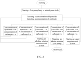
- a method for capturing carbon dioxide including: spraying an alkaline solution through a first spray structure, so that the alkaline solution flowing out through the first spray structure chemically reacts with carbon dioxide gas in gas to absorb the carbon dioxide gas; temporarily storing a solution, obtained after the alkaline solution chemically reacts with the carbon dioxide gas, in a first temporary storage structure, and making the solution stored temporarily in the first temporary storage structure flow out through the first spray structure; detecting at least one of a concentration of hydroxide and a concentration of carbonate of the solution in the first temporary storage structure in real time, and supplementing one of an alkaline solution and water into the first temporary storage structure according to the concentration of the hydroxide and the concentration of the carbonate; and during a process of detecting the at least one of the concentration of the hydroxide and the concentration of the carbonate of the solution in the first temporary storage structure in real time, in a case that the concentration of the hydroxide is detected to be less than or equal to
- a method for making the solution stored temporarily in the first temporary storage structure flow out through the first spray structure includes: starting the first pump body or the third pump body, to pump the solution stored temporarily in the first temporary storage structure into the first spray structure via a pipeline through the first pump body or the third pump body.
- a method for supplementing one of an alkaline solution and water into the first temporary storage structure according to the at least one of the concentration of the hydroxide and the concentration of the carbonate includes: in a case that the concentration of the hydroxide is detected to be less than m and the concentration of the carbonate is detected to be less than n, supplementing the alkaline solution into the first temporary storage structure; and in a case that the concentration of the hydroxide is detected to be less than or equal to m and the concentration of the carbonate is detected to be greater than n, supplementing the water into the first temporary storage structure.
- a method for detecting a concentration of hydroxide of the solution in the first temporary storage structure in real time includes: feeding the solution into a potentiometric titrator, dripping a standard acid with calibrated H+ concentration into the solution, and during a process of titration, continuously stirring the solution added with the standard acid and recording a first-order differential curve of solution potential with respect to a volume of the standard acid added into the solution, until the first-order differential curve of the solution potential reaches a first peak value, and calculating the concentration of the hydroxide of the solution by using the volume of the standard acid consumed at this time.
- a method for detecting a concentration of carbonate of the solution in the first temporary storage structure in real time includes: feeding the solution into a potentiometric titrator, dripping a standard acid with calibrated H+ concentration into the solution, and during a process of titration, continuously stirring the solution added with the standard acid and recording a first-order differential curve of solution potential with respect to a volume of the standard acid added into the solution, until the first-order differential curve of the solution potential reaches a first peak value, recording the volume of the standard acid consumed at this time as V1; continuing to drip the standard acid with the calibrated H+ concentration into the solution, and during a process of the titration, continuing to stir the solution added with the standard acid and recording a first-order differential curve of solution potential with respect to a volume of the standard acid added into the solution, until the first-order differential curve of the solution potential reaches a second peak value, recording the volume of the standard acid consumed at this time as V2; and calculating the concentration of the carbonate of the solution
- a value of m is greater than or equal to 0.1 mol/L and less than or equal to 5 mol/L; and/ or a value of n is greater than or equal to 1 mol/L and less than or equal to 6 mol/L.
- a value of m is greater than or equal to 0.3 mol/L and less than or equal to 2 mol/L; and/or a value of n is greater than or equal to 2 mol/L and less than or equal to 5.5 mol/L.
- the method for capturing the carbon dioxide further includes: regulating electric charge applied to the electrolysis device, to control a molar yield ratio of carbon dioxide gas to hydrogen in the electrolysis device over unit time and/or a yield of carbon dioxide gas and hydrogen in the electrolysis device over unit time.
- a method for regulating electric charge applied to the electrolysis device includes: obtaining a preset value Q of the electric charge applied to the electrolysis device in a case that the molar yield ratio of the carbon dioxide gas to the hydrogen is 1, and increasing nQ on a basis of the preset value Q of the electric charge, to adjust the molar yield ratio of the carbon dioxide gas to the hydrogen, where n is equal to 1, 2, 3, ... , N (N ⁇ n).
- the method for capturing the carbon dioxide further includes: detecting a content of an electrolyte in the electrolysis device in real time, and in a case that the content of the electrolyte is less than a preset value, adding an electrolyte to the electrolysis device; and the electrolyte is one of alkali metal sulfate, alkali metal nitrate and alkali metal phosphate.
- a method for temporarily storing a solution, obtained after the alkaline solution chemically reacts with the carbon dioxide gas, in a first temporary storage structure includes: providing at least two first temporary storage structures for switching operation, and selectively and temporarily storing the solution, obtained after the alkaline solution chemically reacts with the carbon dioxide gas, in each of the at least two first temporary storage structures; and in a case that a concentration of carbonate in one first temporary storage structure reaches a preset concentration value, deactivating the one temporary storage structure, and enabling a remaining temporary storage structure.
- a gas absorption system configured to absorb carbon dioxide gas in environment and uses the above method for capturing the carbon dioxide.
- the gas absorption system includes: a housing provided with an intake port and an exhaust port, the intake port being in communication with the exhaust port, where the exhaust port is located above the intake port; or in a horizontal direction, the intake port and the exhaust port are disposed opposite to each other; a gas pretreatment device disposed inside the housing and located at the intake port for filtering impurities in gas entering the intake port; and a gas absorption assembly disposed inside the housing and located downstream of the gas pretreatment device, the gas absorption assembly including a first liquid supply device and a first spray structure, the first liquid supply device being in communication with the first spray structure to provide an alkaline solution, and the alkaline solution flowing out through the first spray structure chemically reacting with carbon dioxide gas in the gas to absorb the carbon dioxide gas.
- the gas absorption assembly further includes: a first filler disposed opposite to the exhaust port, the first filler being located below the first spray structure; and a first water collector located above the first spray structure.
- the gas absorption assembly further includes: a first temporary storage structure located below the first filler for temporarily storing a solution obtained after the alkaline solution chemically reacts with the carbon dioxide gas; a first pipeline, an end of the first pipeline being in communication with the first temporary storage structure, and another end of the first pipeline being in communication with the first spray structure; and a first pump body disposed on the first pipeline for pumping the solution entering the first temporary storage structure into the first spray structure.
- the gas pretreatment device includes: a second filler disposed opposite to the intake port; a second liquid supply device; and a second spray structure located above the second filler, the second liquid supply device being in communication with the second spray structure.
- the gas pretreatment device further includes: a second water collector disposed opposite to the second filler, where there is one second water collector; or there are a plurality of second water collectors, at least one of the plurality of second water collectors is located at a first side of the second filler, and at least one of the plurality of second water collectors is located at a second side of the second filler.
- the gas pretreatment device further includes: a second temporary storage structure located below the second filler for temporarily storing liquid flowing out through the second filler; a second pipeline, an end of the second pipeline being in communication with the second spray structure, and another end of the second pipeline being in communication with the second temporary storage structure; and a second pump body disposed on the second pipeline for pumping the liquid entering the second temporary storage structure into the second spray structure.
- the second temporary storage structure includes: a first temporary storage body; a first baffle plate disposed inside the first temporary storage body for dividing an inner cavity of the first temporary storage body into a first sub-accommodating cavity and a second sub-accommodating cavity, the first sub-accommodating chamber being located below the second filler, and the second sub-accommodating cavity being in communication with the second pipeline, where the first baffle plate is provided with an overflow hole, and the first sub-accommodating cavity is in communication with the second sub-accommodating cavity through the overflow hole; or an overflow portion is disposed between the first baffle plate and the first temporary storage body, and the first sub-accommodating cavity is in communication with the second sub-accommodating cavity through the overflow portion.
- the second filler includes a plurality of first sub-filler sheets, adjacent two first sub-filler sheets are disposed in a staggered manner and form a flow passage, a surface of each of the plurality of first sub-filler sheets is provided with an interference flow convex portion or an interference flow concave portion located in the flow passage.
- the gas absorption system further includes a filter screen or a filter membrane located between the gas pretreatment device and the intake port.
- the housing is provided with an accommodating cavity, the intake port is in communication with the exhaust port through the accommodating cavity, and the gas absorption assembly is located inside the accommodation cavity, where there is one intake port , and there is one gas pretreatment device; or there are a plurality of intake ports, the plurality of intake ports are disposed around the accommodating cavity, there are a plurality of gas pretreatment devices, and the plurality of gas pretreatment devices and the plurality of intake ports are in a one-to-one correspondence.
- the gas absorption system further includes: a gas delivery device disposed at at least one of the exhaust port and the intake port for delivering gas to an outside of the gas absorption system through the intake port; and a first detection device disposed inside the first temporary storage structure for detecting a concentration of carbonate of a solution; and in a case that a detection value of the first detection device reaches a first preset concentration value, the gas delivery device is controlled to stop running.
- the gas delivery device includes: a fan disposed at the exhaust port; and/or a compressor disposed at the intake port.
- the gas absorption system further includes: a second detection device disposed inside the first temporary storage structure for detecting a concentration of hydroxide of a solution; and in a case that a detection value of the second detection device is less than a second preset concentration value, the first pump body is controlled to start.
- a bottom surface of the first temporary storage structure is provided with a flow guidance slope.
- the gas absorption system further includes: a hydroturbine located below the first temporary storage structure, liquid inside the first temporary storage structure flowing to the hydroturbine through the flow guidance slope; and a generator connected to the hydroturbine.
- the gas absorption system further includes: a stirring device disposed inside the first temporary storage structure.
- the gas absorption system further includes: a gas delivery device disposed at at least one of the exhaust port and the intake port for delivering gas to an outside of the gas absorption system through the intake port.
- the gas delivery device includes: a fan disposed at the exhaust port; and/or a compressor disposed at the intake port.
- the gas absorption assembly includes: a third filler located below the first spray structure; and a third water collector disposed opposite to the third filler, where the third water collector is located between the exhaust port and the third filler; and/ or the third water collector is located between the third filler and the gas pretreatment device.
- the gas absorption assembly further includes: a third temporary storage structure located below the third filler for temporarily storing a solution obtained after the alkaline solution chemically reacts with the carbon dioxide gas, where there is one third temporary storage structure; or there are a plurality of third temporary storage structures, and the plurality of third temporary storage structures are selectively put into use.
- the gas absorption assembly further includes: a second main pipeline, a first end of the second main pipeline being in communication with the first spray structure; a plurality of third branch pipelines, the plurality of third branch pipelines and the plurality of third temporary storage structures being in a one-to-one correspondence, an end of each of the plurality of third branch pipelines being in communication with respective third temporary storage structures, and another end of each of the plurality of third branch pipelines being in communication with a second end of the second main pipeline; and a plurality of second control valves, the plurality of second control valves and the plurality of third branch pipelines being in a one-to-one correspondence, and each of the plurality of second control valves being configured to control an on-off state of respective third branch pipelines; and at any time, at least one of the plurality of second control valves is in an open state.
- the gas absorption assembly further includes: a third detection device disposed on the second main pipeline for detecting a concentration of carbonate of a solution in the second main pipeline; and in a case that a detection value of the third detection device reaches a preset concentration value, a third branch pipeline corresponding to a third temporary storage structure that has been put into use is controlled to be in a disconnected state by at least one second control valve, and at least one another third temporary storage structure is controlled to put into use by at least one another second control valve.
- the gas absorption assembly further includes: a third pump body disposed on one of the second main pipeline and the third branch pipeline for pumping the solution entering the third temporary storage structure into the first spray structure.
- the gas pretreatment device includes: a fourth filler disposed opposite to the intake port; a third liquid supply device; a third spray structure located above the fourth filler, the third liquid supply device being in communication with the third spray structure; and a fourth water collector disposed opposite to the fourth filler.
- the gas pretreatment device further includes: a fourth temporary storage structure located below the fourth filler for temporarily storing liquid flowing out through the fourth filler; a third main pipeline, an end of the third main pipeline being in communication with the third spray structure, and another end of the third main pipeline being in communication with the fourth temporary storage structure; and a fourth pump body disposed on the third main pipeline for pumping the liquid entering the fourth temporary storage structure into the third spray structure.
- a fourth temporary storage structure located below the fourth filler for temporarily storing liquid flowing out through the fourth filler
- a third main pipeline an end of the third main pipeline being in communication with the third spray structure, and another end of the third main pipeline being in communication with the fourth temporary storage structure
- a fourth pump body disposed on the third main pipeline for pumping the liquid entering the fourth temporary storage structure into the third spray structure.
- the four temporary storage structure includes: a second temporary storage body; a second baffle plate disposed inside the second temporary storage body to divide an inner cavity of the second temporary storage body into a third sub-accommodating cavity and a fourth sub-accommodating cavity, the third sub-accommodating cavity being located below the fourth filler, and the fourth sub-accommodating cavity being in communication with the third main pipeline, where the second baffle plate is provided with an overflow hole, and the third sub-accommodating cavity is in communication with the fourth sub-accommodating cavity through the overflow hole; or an overflow portion is disposed between the second baffle plate and the second temporary storage body, and the third sub-accommodating cavity is in communication with the fourth sub-accommodating cavity through the overflow portion.
- the fourth filler includes a plurality of second sub-filler sheets, adjacent two second sub-filler sheets are disposed in a staggered manner and form a flow passage, a surface of each of the plurality of second sub-filler sheets is provided with an interference flow convex portion or an interference flow concave portion located in the flow passage.
- the gas absorption system further includes an electrolysis device, the electrolysis device is located downstream of the first temporary storage structure, and a carbonic acid solution discharged through the first temporary storage structure is electrolyzed by the electrolysis device, so that potassium hydroxide and hydrogen are generated at a cathode of the electrolysis device, and gas obtained by mixing oxygen and carbon dioxide is generated at an anode of the electrolysis device; and the potassium hydroxide is used for absorbing carbon dioxide of the gas absorption system.
- the alkaline solution is sprayed through the first spray structure, so that the alkaline solution flowing out through the first spray structure chemically reacts with the carbon dioxide gas in the gas to absorb the carbon dioxide gas.
- the solution obtained after the alkaline solution chemically reacts with the carbon dioxide gas, is temporarily stored in the first temporary storage structure, and the solution stored temporarily in the first temporary storage structure flows out again through the first spray structure, so as to achieve recycling of the solution.
- the at least one of the concentration of the hydroxide and the concentration of the carbonate of the solution in the first temporary storage structure is detected in real time, and one of the alkaline solution and the water is supplemented into the first temporary storage structure according to the concentration of the hydroxide and the concentration of the carbonate.
- the concentration of the hydroxide and the concentration of the carbonate of the solution in a final state are precisely controlled by means of alkaline solution supplement or water addition, so as to meet requirements of a process of a subsequent electrolysis, thereby reducing energy consumption of an overall system, and further solving the problems in that capture efficiency of carbon dioxide gas and overall energy consumption of a system for capturing carbon dioxide are relatively difficult to control in the prior art, and thus improving capture efficiency of a system for capturing carbon dioxide.
- the first pump body or the third pump body is controlled to stop running, so that the solution stored temporarily in the first temporary storage structure enters the electrolysis device for the electrolysis.
- directional words such as “above” and “below” are usually referred to the directions shown in the accompanying drawings, or the vertical direction, the perpendicular direction or the gravitational direction; similarly, for ease of understanding and description, directional words “left” and “right” are usually referred to the left and right shown in the accompanying drawings; and directional words “inside” and “outside” are referred to inner and outer contours of each component itself.
- the above directional words are not intended to limit the present application.
- the present application provides a method for capturing carbon dioxide and a gas absorption system.
- a method for capturing carbon dioxide includes:
- the alkaline solution is sprayed through the first spray structure, so that the alkaline solution flowing out through the first spray structure chemically reacts with the carbon dioxide gas in the gas to absorb the carbon dioxide gas.
- the solution obtained after the alkaline solution chemically reacts with the carbon dioxide gas, is temporarily stored in the first temporary storage structure, and the solution stored temporarily in the first temporary storage structure flows out again through the first spray structure, so as to achieve recycling of the solution.
- the at least one of the concentration of the hydroxide and the concentration of the carbonate of the solution in the first temporary storage structure is detected in real time, and one of the alkaline solution and the water is supplemented into the first temporary storage structure according to the concentration of the hydroxide and the concentration of the carbonate.
- the concentration of the hydroxide and the concentration of the carbonate of the solution in a final state are precisely controlled by means of alkaline solution supplement or water addition, so as to meet requirements of a process of a subsequent electrolysis, thereby reducing energy consumption of an overall system, and further solving the problems in that capture efficiency of carbon dioxide gas and overall energy consumption of a system for capturing carbon dioxide are relatively difficult to control in the prior art, and thus improving capture efficiency of a system for capturing carbon dioxide.
- the first pump body or the third pump body is controlled to stop running, so that the solution stored temporarily in the first temporary storage structure enters the electrolysis device for the electrolysis.
- a method for making the solution stored temporarily in the first temporary storage structure flow out through the spray structure includes: starting the first pump body or the third pump body, to pump the solution stored temporarily in the first temporary storage structure into the spray structure via a pipeline through the first pump body or the third pump body.
- the solution stored temporarily in the first temporary storage structure is pumped into the spray structure via the pipeline through the first pump body or the third pump body, so as to reuse the above solution, thereby achieving the recycling of the solution, and thus avoiding waste of resource.
- the solution is pumped into the spray structure through the first pump body or the third pump body, so as to ensure that the alkaline solution can be sprayed through the spray structure to react with CO 2 , thereby improving spray reliability of the spray structure, and thus improving operational reliability of a system for capturing carbon dioxide.
- a method for supplementing one of an alkaline solution and water into the first temporary storage structure according to the at least one of the concentration of the hydroxide and the concentration of the carbonate includes:
- an initial alkaline solution is placed in the first temporary storage structure located at a bottom of a system for capturing carbon dioxide, the first pump body or the third pump body starts to capture the carbon dioxide gas, and the concentration of the hydroxide and the concentration of the carbonate are detected in real time.
- the concentration of the hydroxide of the solution in the first temporary storage structure is greater than or equal to m and the concentration of the carbonate of the solution in the first temporary storage structure is less than n, or in the case that the concentration of the hydroxide of the solution in the first temporary storage structure is greater than m and the concentration of the carbonate of the solution in the first temporary storage structure is greater than or equal to n, the first pump body or the third pump body operates continuously, and no related measures are taken; in the case that the concentration of the hydroxide of the solution in the first temporary storage structure is less than m and the concentration of the carbonate of the solution in the first temporary storage structure is less than n, an alkaline solution supplemented device starts and the alkaline solution is supplemented into the first temporary storage structure, and the concentration of the hydroxide and the concentration of the carbonate in the first temporary storage structure continue to be detected; and in the case that the concentration of the hydroxide of the solution in the first temporary storage structure is less than or equal to m and the concentration of the carbon
- a method for detecting a concentration of hydroxide of the solution in the first temporary storage structure in real time includes: feeding the solution into a potentiometric titrator, dripping a standard acid with calibrated H+ concentration into the solution, and during a process of titration, continuously stirring the solution added with the standard acid and recording a first-order differential curve of solution potential with respect to a volume of the standard acid added into the solution, until the first-order differential curve of the solution potential reaches a first peak value, and calculating the concentration of the hydroxide of the solution by using the volume of the standard acid consumed at this time.
- a calibrated HCl solution with an actual concentration of 0.2404 mol/L is used as a titrant, and the calibrated HCl solution is slowly dripped into the solution, until a pH value of the solution is below 2, changes in an added volume of the standard acid and a pH value of the solution are recorded, and the recorded added volume of the standard acid and the recorded pH value are plotted as a pH-V curve, a first-order numerical differential curve of ⁇ pH/ ⁇ V-V is calculated and then is plotted according to the recorded curve, a maximum value of the above first-order numerical differentiation is taken as an equivalence point, a titration volume at the equivalence point is obtained through the first-order numerical differentiation, the corresponding equivalence point is the EP1 shown in a pH-V change chart of the volume of the standard acid, and the concentration of the OH - of the solution is calculated by using the volume at the equivalence point and a concentration at the equivalence point.
- a standard acid used in calibration experiments is adopted (i.e. a H+ concentration of a prepared hydrochloric acid solution is calibrated by using well-known methods), which is implemented in accordance with the National Standards GB/T601 - 2003.
- This method is calibrated twice, for the first calibration, a concentration of a standard alkali is calibrated first, and then a calibrated standard alkali solution with a known concentration is used to calibrate the standard acid.
- An embodiment of calibrating the alkali solution is to dry potassium hydrogen phthalate primary standard at 105 °C to 110 °C to a constant weight, dissolve 110 g of sodium hydroxide into 100 ml of water without carbon dioxide, place a solution, obtained after 110 g of the sodium hydroxide is dissolved into 100 ml of the water without carbon dioxide, in a closed polyethylene container until the solution is clear, take 10.8 ml of the clear solution at a top, and dilute the clear solution with water to 1000 ml to prepare a sodium hydroxide titrant.
- the potassium hydrogen phthalate primary standard that has been dried to the constant weight is weighed for 0.1377 g, 0.1377 g of the potassium hydrogen phthalate primary standard is added with water to 50ml - 60 ml, the potassium hydrogen phthalate primary standard added with the water is stirred until the potassium hydrogen phthalate primary standard added with the water is dissolved completely, and titrating and plotting are performed by an automatic potentiometric titrator using the same final judging principle as the above embodiments, so that a titration volume at an equivalence point is obtained through first-order numerical differentiation in the above chart, a pH value at the equivalence point is 8.81, and a concentration of the sodium hydroxide titrant is calculated accordingly.
- hydrochloric acid titrant is calibrated by using a titrant with a standard calibrated concentration. 27 ml of hydrochloric acid is diluted with water to 1000ml to prepare the hydrochloric acid titrant.
- a method for detecting a concentration of carbonate of the solution in the first temporary storage structure in real time includes:
- a value of m is greater than or equal to 0.1 mol/L and less than or equal to 5 mol/L; and/ or a value of n is greater than or equal to 1 mol/L and less than or equal to 6 mol/L.
- m and value of n are flexible, so as to meet different usage requirements and working conditions.
- a value of m is greater than or equal to 0.3 mol/L and less than or equal to 2 mol/L; and/or a value of n is greater than or equal to 2 mol/L and less than or equal to 5.5 mol/L.
- m and value of n are flexible, so as to meet different usage requirements and working conditions.
- the value of m is 0.1 mol/L and the value of n is 6 mol/L.
- the alkaline solution is sprayed through the spray structure, so that the alkaline solution flowing out through the spray structure chemically reacts with the carbon dioxide gas in the gas, and during a process for capturing carbon dioxide gas, the concentration of the hydroxide and the concentration of the carbonate of the solution in the first temporary storage structure are detected in real time.
- the concentration of the hydroxide of the solution in the first temporary storage structure is greater than or equal to 0.1 mol/L and the concentration of the carbonate of the solution in the first temporary storage structure is less than 6 mol/L, or in the case that the concentration of the hydroxide of the solution in the first temporary storage structure is greater than 0.1 mol/L and the concentration of the carbonate of the solution in the first temporary storage structure is greater than or equal to 6 mol/L, the first pump body or the third pump body operates continuously, and no related measures are taken; in the case that the concentration of the hydroxide of the solution in the first temporary storage structure is less than 0.1 mol/L and the concentration of the carbonate of the solution in the first temporary storage structure is less than 6 mol/L, an alkaline solution supplemented device starts and the alkaline solution is supplemented into the first temporary storage structure, and the concentration of the hydroxide and the concentration of the carbonate in the first temporary storage structure continue to be detected; and in the case that the concentration of the hydroxide of the
- the first pump body or the third pump body is controlled to stop running, so that the solution stored temporarily in the first temporary storage structure enters the electrolysis device for the electrolysis.
- n is not limited thereto and may be adjusted according to working conditions and usage requirements.
- the unit kWh/kgCO 2 represents: an amount of electricity (kWh) consumed by an electrolysis device for every 1 kg of CO 2 produced during a process of an electrolysis.
- the method for capturing the carbon dioxide further includes: regulating electric charge applied to the electrolysis device, so as to control a molar yield ratio of carbon dioxide gas to hydrogen in the electrolysis device over unit time and/or a yield of carbon dioxide gas and hydrogen in the electrolysis device over unit time.
- the absorbed carbon dioxide gas is released, while a high-value hydrogen is generated.
- the carbon dioxide gas and the hydrogen may synthesize a variety of chemicals, which provides a good solving basis for comprehensive utilization of carbon dioxide gas.
- a molar yield ratio of carbon dioxide gas to hydrogen required for synthesizing different chemicals is different, and therefore, how to control an output ratio of carbon dioxide gas and hydrogen during a process for electrolytic regeneration of inorganic alkali is also necessary.
- An electrolyte component is added to the electrolysis device, so as to enhance conductivity, thereby reducing energy consumption of an electrolysis.
- Water may also be electrolyzed after carbonate is electrolyzed completely, so as to further generate hydrogen, and therefore, the molar yield ratio of carbon dioxide gas to hydrogen in the electrolysis device over unit time may be controlled by changing the applied electric charge, so that an application scope of a system is greatly improved.
- a method for regulating electric charge applied to the electrolysis device includes: obtaining a preset value Q of the electric charge applied to the electrolysis device in a case that the molar yield ratio of the carbon dioxide gas to the hydrogen is 1, and increasing nQ on a basis of the preset value Q of the electric charge, to adjust the molar yield ratio of the carbon dioxide gas to the hydrogen, where n is equal to 1, 2, 3, ... , N (N ⁇ n).
- an electrolyte added to the electrolysis device is potassium sulfate
- a concentration of the potassium sulfate at an anode is set to be 0.5 mol/L
- the electric charge applied to the electrolysis device is controlled, so that electric charge obtained by 1 mol of a carbonate solution is 53.6 A ⁇ h, and the molar yield ratio of the carbon dioxide gas to the hydrogen is 1: 1.
- the yield of the carbon dioxide gas is 0, and the yield of the hydrogen increases by 1 mol, i.e., the molar yield ratio of the carbon dioxide gas to the hydrogen over unit time becomes 1: 2, so that the molar yield ratio of the carbon dioxide gas to the hydrogen is adjustable.
- the electric charge applied to the electrolysis device is controlled, so that the electric charge obtained by 1 mol of the carbonate solution is 54.0 A ⁇ h, power consumption of the electrolysis device is measured to be 3.30 kWh/kgCO 2 , and the molar yield ratio of the carbon dioxide gas to the hydrogen is 1: 1.01.
- the method for capturing the carbon dioxide further includes: detecting a content of an electrolyte in the electrolysis device in real time, and in a case that the content of the electrolyte is less than a preset value, adding an electrolyte to the electrolysis device; and the electrolyte is one of alkali metal sulfate, alkali metal nitrate and alkali metal phosphate.
- the preset value is 0.
- the electrolyte is added to the anode of the electrolysis device, and the applied electric charge is changed, so that the molar yield ratio of the carbon dioxide gas to the hydrogen gas in the electrolysis device over unit time is controlled, thereby ensuring capture efficiency of carbon dioxide and greatly reducing overall energy consumption of a system, and thus facilitating controlling capture efficiency of carbon dioxide gas and overall energy consumption of a system for capturing carbon dioxide.
- the alkali metal sulfate is one of potassium sulfate and sodium sulfate.
- the alkali metal nitrate is one of potassium nitrate and sodium nitrate.
- the alkali metal phosphate is one of potassium phosphate and sodium phosphate.
- the alkaline solution is alkali metal hydroxide.
- a method for temporarily storing a solution, obtained after the alkaline solution chemically reacts with the carbon dioxide gas, in a first temporary storage structure includes: providing at least two first temporary storage structures for switching operation, and selectively and temporarily storing the solution, obtained after the alkaline solution chemically reacts with the carbon dioxide gas, in each of the at least two first temporary storage structures; and in a case that a concentration of carbonate in one first temporary storage structure reaches a preset concentration value, deactivating the one temporary storage structure, and enabling a remaining temporary storage structure.
- a second first temporary storage structure enables, so that carbon dioxide is captured by the alkaline solution in the first temporary storage structure, a carbonate solution in the first first temporary storage structure is emptied, and then a fresh alkaline solution is supplemented into the first first temporary storage structure again, and after the concentration of the carbonate in the second first temporary storage structure reaches the preset concentration value, the first first temporary storage structure enables again, and these processes are repeated alternately in such a way.
- the alkali metal hydroxide is one of potassium oxide and sodium hydroxide.
- a gas absorption system is configured to absorb carbon dioxide gas in environment
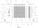
- the gas absorption system includes a housing 10, a gas pretreatment device 20 and a gas absorption assembly 30.
- the housing 10 is provided with an intake port 11 and an exhaust port 12, the intake port 11 is in communication with the exhaust port 12, and the exhaust port 12 is located above the intake port 11.
- the gas pretreatment device 20 is disposed inside the housing 10 and is located at the intake port 11 for filtering impurities in gas entering the intake port 11.
- the gas absorption assembly 30 is disposed inside the housing 10 and is located downstream of the gas pretreatment device 20, the gas absorption assembly 30 includes a first liquid supply device and a first spray structure 31, the first liquid supply device is in communication with the first spray structure 31 to provide an alkaline solution, and the alkaline solution flowing out through the first spray structure 31 chemically reacts with carbon dioxide gas in the gas to absorb the carbon dioxide gas.
- the gas pretreatment device 20 is disposed inside the housing 10 and is located at the intake port 11, and the gas absorption assembly 30 is located downstream of the gas pretreatment device 20.
- the gas pretreatment device 20 first, and impurities in the air or the flue gas are filtered by the gas pretreatment device 20, which avoids accumulation of the above impurities in the gas absorption system, and avoids affecting efficiency of absorbing and capturing carbon dioxide gas by the gas absorption system caused by the above impurities entering the gas absorption assembly 30, so as to solve problems in that the impurities such as solid particles mixing in the air or the flue gas are easily accumulated in a system for capturing CO 2 in the prior art, and thus reducing an operation cost and a maintenance cost of the gas absorption system.
- Absorbing the impurities in the air or the flue gas can also improve a purity of
- the alkaline solution is one of sodium hydroxide, potassium hydroxide, potassium carbonate and sodium carbonate, and solutions with different concentrations may be prepared with deionized water as needed.
- an alkaline solution is used as an absorbent, which not only can capture CO 2 with a high concentration, but also can capture CO 2 with a low concentration, so as to realize the capturing of CO 2 with a wide concentration range.
- the gas absorption system is a countercurrent absorption system, i.e., an intake direction of the air or the flue gas is perpendicular to an exhaust direction of the air or the flue gas.
- the plurality of first spray structures 31 are disposed at intervals along a flow direction of the gas in the gas absorption system, thereby increasing a quantity of the alkaline solution sprayed out through the first spray structures 31, and thus ensuring that the alkaline solution sprayed out through the first spray structures 31 can fully capture and absorb CO 2 in the air or the flue gas.
- a side wall of the housing 10 is provided with a staircase 80, and the workers may climb to a top of the housing 10 through the staircase 80 to repair the gas absorption system.
- the first spray structure 31 is a nozzle.
- the gas absorption assembly 30 further includes a first filler 32 and a first water collector 33.
- the first filler 32 is disposed opposite to the exhaust port 12, and the first filler 32 is located below the first spray structure 31.
- the first water collector 33 is located above the first spray structure 31. In this way, disposal of the first filler 32 provides sufficient contact surface for the CO 2 and the alkaline solution, so that the CO 2 in the air or the flue gas fully reacts with the alkaline solution, which further improves efficiency of capturing and absorbing CO 2 by the gas absorption assembly 30.
- the first water collector 33 is configured to recover water vapor in the housing to reduce fine water droplet drift carried in the gas discharged through the exhaust port 12, which can effectively prevent a loss of liquid water caused by a phenomenon of water splashing at the exhaust port 12.
- the alkaline solution falls in a form of droplets from the first spray structure 31 into the first filler 32, and flows in a form of a liquid film in the first filler 32, and the alkaline solution falls in the form of the droplets into the first temporary storage structure 34 after passing through the first filler 32.
- the gas enters the gas absorption assembly 30 after the impurities carried in the air or the flue gas are removed through the gas pretreatment device 20, and the pretreated gas is in full contact with the alkaline solution in a water spraying area and the first filler 32 of the gas absorption assembly 30, so that CO 2 in the air or the flue gas chemically reacts with the alkaline solution, thereby capturing the CO 2 .
- the captured CO 2 exists in the first temporary storage structure 34 in a form of carbonate and bicarbonate ions, and the first pump body 36 is configured to deliver the solution obtained after the reacting to a subsequent process system for processing.
- the first temporary storage structure 34 is provided with a first liquid supply device to supplement water and hydroxide consumed in the solution.
- the first filler 32 is a thin-film water-spraying filler.
- the first water collector 33 is a PVC water collector, and the first water collector 33 is supported by a bracket.
- the gas absorption assembly 30 further includes a first temporary storage structure 34, a first pipeline 35 and a first pump body 36.
- the first temporary storage structure 34 is located below the first filler 32 for temporarily storing the solution obtained after the alkaline solution chemically reacts with the carbon dioxide gas.
- An end of the first pipeline 35 is in communication with the first temporary storage structure 34, and another end of the first pipeline 35 is in communication with the first spray structure 31.
- the first pump body 36 is disposed on the first pipeline 35 for pumping the solution entering the first temporary storage structure 34 into the first spray structure 31.
- the solution obtained after the alkaline solution chemically reacts with the carbon dioxide gas is stored in the first temporary storage structure 34, which on the one hand facilitates post-treatment of the above solution, and on the other hand may achieve recycling of the solution, so as to avoid wasting of resource.
- the solution is pumped into the first spray structure 31 through the first pump body 36, so as to ensure that the alkaline solution can be sprayed through the first spray structure 31 to react with CO 2 , thereby improving spray reliability of the first spray structure 31 and operational reliability of the gas absorption system.
- the first temporary storage structure 34 and the first liquid supply device are of a same structure.
- an alkaline solution is disposed in the first temporary storage structure 34, the alkaline solution is sprayed to the first filler 32 through the first spray structure 31 to react with CO 2 in the air or the flue gas, and the solution obtained after the reacting is stored temporarily in the first temporary storage structure 34, so that the solution enters the first spray structure 31 again to continue spraying, so as to achieve recycling of the alkaline solution, until a concentration of carbonate in the alkaline solution reaches a preset concentration value, CO 2 capture and CO 2 absorption are stopped at this time, and the solution in the first temporary storage structure 34 is replaced with the alkaline solution.
- first temporary storage structure 34 is in communication with the first liquid supply device, so as to provide the alkaline solution for the first spray structure 31 through the first liquid supply device, and the solution, obtained after the alkaline solution reacts with the CO 2 , is stored temporarily in the first temporary storage structure 34, so that the solution enters the first spray structure 31 again to continue spraying.
- first temporary storage structure 34 there is one first temporary storage structure 34; or there are a plurality of first temporary storage structures 34, and the plurality of first temporary storage structures 34 are selectively put into use.
- a usage state (putting into use or not putting into use) of the first temporary storage structure 34 may be adjusted according to the concentration of the carbonate in the first temporary storage structure 34, so as to supplement a fresh alkaline solution into the first spray structure 31, thereby achieving rapid and efficient CO 2 capture of the gas absorption system.
- the gas absorption assembly 30 further includes a first pipeline 35, a plurality of first branch pipelines and a plurality of first control valves.
- a first end of the first pipeline 35 is in communication with the first spray structure 31.
- the plurality of first branch pipelines and the plurality of first temporary storage structures 34 are in a one-to-one correspondence, an end of each of the plurality of first branch pipelines is in communication with respective first temporary storage structures 34, and another end of each of the plurality of first branch pipelines is in communication with a second end of the first pipeline 35.
- the plurality of first control valves and the plurality of first branch pipelines are in a one-to-one correspondence, and each of the plurality of first control valves is configured to control an on-off state of respective first branch pipelines. At any time, at least one of the plurality of first control valves is in an open state. In this way, the on-off state of the first branch pipeline is controlled by the first control valve corresponding to the first branch pipeline, so as to control a usage state of the first temporary storage structure 34 in communication with the first branch pipeline, thereby making it easier and simpler for the workers to control the usage state of the first temporary storage structure 34, and thus reducing control difficulty.
- Adopting the above arrangement enables the plurality of first temporary storage structures 34 to be connected in parallel, and at any time, the at least one of the plurality of temporary storage structures 34 is controlled to be put into use, so as to provide the alkaline solution for the first spray structure 31.
- the gas pretreatment device 20 includes a second filler 21, a second liquid supply device and a second spray structure 22.
- the second filler 21 is disposed opposite to the intake port 11.
- the second spray structure 22 is located above the second filler 21, and the second liquid supply device is in communication with the second spray structure 22.
- the second spray structure 22 is configured to spray water, in a process of filtering impurities in the air or the flue gas by the gas pretreatment device 20, disposal of the second filler 21 provides sufficient contact surface for the impurities in the air or the flue gas and water, so as to ensure that the water can sink the impurities, thereby preventing the impurities from entering the gas absorption assembly 30.
- a humidity of the gas may be increased, so as to reduce an evaporation rate of water in the gas absorption system, thereby reducing a loss of deionized water, and thus reducing a cost of capturing CO 2 .
- the second liquid supply device is configured to supply tap water.
- the second spray structure 22 is a nozzle.
- the second filler 21 is a thin-film water-spraying filler.
- the second water collector 23 is a PVC water collector.
- the gas absorption assembly 30 further includes a first main pipeline 51 and a second branch pipeline 52.
- the first main pipeline 51 is connected to the first pipeline 35, there are a plurality of second branch pipelines 52, and each of the plurality of second branch pipelines 52 is connected to the first main pipeline 51.
- the gas pretreatment device 20 further includes a second water collector 23.
- the second water collector 23 is disposed opposite to the second filler 21.
- the second water collector 23 is configured to recover water vapor in the housing, so as to reduce fine water droplet drift carried in the gas discharged through the exhaust port 12, which can effectively prevent a loss of liquid water caused by a phenomenon of water splashing at the exhaust port 12.
- adopting the above arrangement makes selection of an amount of second water collectors 23 more flexible, so as to meet different usage requirements and working conditions, thereby improving preparation flexibility of the workers.
- Disposal of the plurality of second water collectors 23 can improve recovery efficiency of water vapor, which further prevents a loss of liquid water caused by a phenomenon of water splashing at the exhaust port 12.
- a second water collector 23 is located at the first side of the second filler 21, and another second water collector 23 is located at the second side of the second filler 21, so as to fully recover water vapor in the housing.
- the amount of second water collectors 23 is not limited thereto and may be adjusted according to working conditions and usage requirements.
- the amount of second water collectors 23 is three, four, five and multiple.
- the gas pretreatment device 20 further includes a second temporary storage structure 24, a second pipeline 25 and a second pump body 26.
- the second temporary storage structure 24 is located below the second filler 21 for temporarily storing liquid flowing out through the second filler 21.
- An end of the second pipeline 25 is in communication with the second spray structure 22, and another end of the second pipeline 25 is in communication with the second temporary storage structure 24.
- the second pump body 26 is disposed on the second pipeline 25 for pumping the liquid entering the second temporary storage structure 24 into the second spray structure 22.
- water flowing out through the second filler 21 is stored in the second temporary storage structure 24, so as to achieve recycling of water, thereby avoiding waste of resource.
- the water is pumped into the second spray structure 22 through the second pump body 26, so as to ensure that water can be sprayed through the second spray structure 22 to sink the impurities, thereby improving spray reliability of the second spray structure 22 and operational reliability of the gas pretreatment device 20.
- the second temporary storage structure 24 includes a first temporary storage body and a first baffle plate.
- the first baffle plate is disposed inside the first temporary storage body for dividing an inner cavity of the first temporary storage body into a third sub-accommodating cavity and a fourth sub-accommodating cavity, the third sub-accommodating cavity is located below the second filler 21, and the fourth sub-accommodating cavity is in communication with the second pipeline 25.
- the first baffle plate is provided with an overflow hole, and the third sub-accommodating cavity is in communication with the fourth sub-accommodating cavity through the overflow hole; or an overflow portion is disposed between the first baffle plate and the first temporary storage body, and the third sub-accommodating cavity is in communication with the fourth sub-accommodating cavity through the overflow portion.
- adopting the above arrangement of the first baffle plate ensures that after the impurities are sprayed through the second spray structure 22, the impurities entering the third sub-accommodating cavity are fully deposited in the third sub-accommodating cavity, thereby preventing the second spray structure 22 from being blocked due to the impurities entering the second pipeline 25, and thus improving spray efficiency of the second spray structure 22.
- Adopting the above arrangement makes an overflow mode of liquid in the second temporary storage structure 24 more diverse, so as to meet different usage requirements and working conditions, thereby improving preparation flexibility of the workers.
- the second filler 21 includes a plurality of first sub-filler sheets, adjacent two first sub-filler sheets are disposed in a staggered manner and form a flow passage, a surface of each of the plurality of first sub-filler sheets is provided with an interference flow convex portion or an interference flow concave portion located in the flow passage.
- the gas absorption system further includes a filter screen or a filter membrane located between the gas pretreatment device 20 and the intake port 11.
- a filter screen or a filter membrane located between the gas pretreatment device 20 and the intake port 11.
- a bottom surface of the first temporary storage structure 34 is provided with a flow guidance slope.
- the solution collect at a relatively low position on a bottom surface of the first temporary storage structure 34, thereby facilitating entry of the above solution into the first pipeline 35, and thus avoiding increasing cleaning difficulty for the workers due to accumulation of the solution at a dead zone of the first temporary storage structure 34.
- the bottom surface of the first temporary storage structure 34 is an inclined surface. In this way, adopting the above arrangement makes the bottom surface of the first temporary storage structure 34 easier to process and implement, thereby reducing a preparation cost of the gas absorption system.
- the bottom surface of the first temporary storage structure 34 is a conical surface.
- the second temporary storage structure 24 and the second liquid supply device are of a same structure, so as to reduce an amount of structures of the gas absorption system, which facilitates disassembly and maintenance of the gas absorption system for the workers.
- the second temporary storage structure 24 is in communication with the second liquid supply device, so as to provide water for the second spray structure 22 through the second liquid supply device, and water and impurities flowing out through the second filler 21 are stored temporarily in the second temporary storage structure 24, so that the water enters the second spray structure 22 again to continue spraying.
- the housing 10 is provided with an accommodating cavity 13, the intake port 11 is in communication with the exhaust port 12 through the accommodating cavity 13, and the gas absorption assembly 30 is located inside the accommodation cavity 13.
- adopting the above arrangement makes selection of an amount of intake ports 11 more flexible, so as to meet different usage requirements and working conditions, thereby improving preparation flexibility of the workers.
- each of the gas pretreatment devices 20 is configured to filter impurities in the air or the flue gas entering through respective intake ports 11, so as to ensure that all the air or all the flue gas entering the gas absorption system are filtered for impurities, thereby avoiding affecting CO 2 capture efficiency of the gas absorption system due to accumulation of impurities in the gas absorption system.
- selection of an amount of intake ports 11 is not limited thereto and may be adjusted according to working conditions and usage requirements.
- the amount of intake ports 11 is three, four, five and multiple.
- selection of an amount of gas pretreatment devices 20 is not limited thereto, as long as the amount of gas pretreatment devices 20 is consistent with the amount of intake ports 11.
- the gas absorption system further includes a gas delivery device 40 and a first detection device.
- the gas delivery device 40 is disposed at at least one of the exhaust port 12 and the intake port 11 for delivering gas to an outside of the gas absorption system through the intake port 11.
- the first detection device is disposed inside the first temporary storage structure 34 for detecting a concentration of carbonate of a solution. In a case that a detection value of the first detection device reaches a first preset concentration value, the gas delivery device 40 is controlled to stop running.
- the gas absorption system in the case that the detection value of the first detection device reaches the preset concentration value, it is determined that the gas absorption system has completed capture and absorption of CO 2 in the air or the flue gas, and the gas absorption system is controlled to stop exhausting gas at this time; or it is determined that capture of CO 2 by an alkaline solution is saturated, and the gas absorption system is controlled to supply the alkaline solution at this time.
- the gas delivery device 40 includes a fan, and the fan is disposed at the exhaust port 12; and/or the gas delivery device 40 includes a compressor, and the compressor is disposed at the intake port.
- gas obtained after the absorption and located in the gas absorption system, can be sucked out of the gas absorption system, so as to ensure that gas can smoothly flow in the gas absorption system.
- the compressor is configured to compress gas at the intake port into high-pressure gas, and then the high-pressure gas enters the gas absorption system, thereby increasing a flow rate of the gas, and thus improving CO 2 capture efficiency of the gas absorption system.
- the gas delivery device 40 includes the fan, and the fan is disposed at the exhaust port 12.
- the detection value of the first detection device reaches the preset concentration value, it is determined that capacity of CO 2 capture and CO 2 absorption of the alkaline solution in the first temporary storage structure 34 that has been put into use cannot meet usage requirements of the gas absorption system, and the first temporary storage structure 34 that has been put into use is replaced at this time, so as to improve stability of capability of capturing and absorbing CO 2 by the gas absorption system.
- the gas absorption system further includes a second detection device.
- the second detection device is disposed inside the first temporary storage structure 34 for detecting a concentration of hydroxide of a solution; and in a case that a detection value of the second detection device is less than a second preset concentration value, the first pump body 36 is controlled to start.
- the detection value of the second detection device is less than the second preset concentration value
- the gas absorption assembly 30 further includes a first liquid level gauge, and the first liquid level gauge is disposed in the first temporary storage structure 34 for detecting a height of a solution in the first temporary storage structure 34.
- a liquid level is lower than a first liquid level value
- water is supplemented into the first temporary storage structure 34 by a water replenishment pump, and in a case that the liquid level reaches a preset liquid level, the supplement of the water is stopped.
- the gas pretreatment device 20 further includes a second liquid level gauge, and the second liquid level gauge is disposed in the second temporary storage structure 24 for detecting a height of a solution in the second temporary storage structure 24.
- a liquid level is lower than a second liquid level value
- water is supplemented into the second temporary storage structure 24 by a water replenishment pump, and in a case that the liquid level reaches a preset liquid level, the supplement of the water is stopped.
- the gas absorption system further includes a wind duct 60 and a gearbox 70.
- the wind duct 60 is connected to the housing 10 and is located at the exhaust port 12 for guiding a flow of gas discharged through the exhaust port.
- the gearbox 70 is connected to a fan by means of a driving manner, so as to drive the fan to operate.
- first filler 32 there is one first filler 32; or, there are a plurality of first fillers 32, and the plurality of first fillers 32 are disposed at intervals along a length direction of the gas absorption system.
- a spray density of the first spray structure 31 ranges from 0 m 3 /m 2 * h to 20 m 3 /m 2 * h, and deionized water is used.
- the gas absorption system further includes a hydroturbine and a generator.
- the hydroturbine is located below the first temporary storage structure 34, and liquid inside the first temporary storage structure 34 flows to the hydroturbine through the flow guidance slope.
- the generator is connected to the hydroturbine. In this way, during an operation of the gas absorption system, the hydroturbine is driven to rotate by a liquid potential energy, thereby achieving a power generation function of the generator, and the generator may supply power to the first pump body 36 and the second pump body 26, so as to recycle the liquid potential energy, thereby reducing overall energy consumption of the gas absorption system.
- the gas absorption system further includes a stirring device.
- the stirring device is disposed inside the first temporary storage structure 34. In this way, adopting the arrangement of the stirring device makes mixing of fresh water and fresh alkaline solution more uniform.
- the method for capturing the carbon dioxide is applied to a gas absorption system, and the gas absorption system is configured to absorb carbon dioxide gas.
- the gas absorption system includes a housing and a gas absorption assembly, the housing is provided with an intake port and an exhaust port, and the intake port and exhaust port are disposed opposite to each other.
- the gas absorption assembly is disposed inside the housing and is located downstream of a gas pretreatment device, and the gas absorption assembly includes a liquid supply device and a spray structure that are in communication with each other for providing an alkaline solution; and the alkaline solution flowing out through the spray structure chemically reacts with carbon dioxide gas in gas to absorb the carbon dioxide gas.
- the gas absorption system is a cross-flow absorption system or a countercurrent absorption system.
- the cross-flow absorption system is that an intake direction of air or flue gas is consistent with an exhaust direction of the air or the flue gas.
- the countercurrent absorption system is that there is an included angle between the intake direction of the air or the flue gas and the exhaust direction of the air or the flue gas.
- the spray structure is a nozzle.
- the gas absorption assembly includes a filler and a water collector.
- the filler is located below the spray structure.
- the water collector is disposed opposite to the filler. In this way, disposal of the filler provides sufficient contact surface for CO 2 in the air or the flue gas and the alkaline solution, so that the CO 2 in the air or the flue gas fully reacts with the alkaline solution, which further improves efficiency of capturing and absorbing CO 2 by the gas absorption assembly.
- the water collector is configured to recover absorption liquid in the gas absorption assembly to reduce fine water droplet drift carried in gas discharged through the gas absorption assembly. Adopting the above arrangement makes positioning of the water collector more flexible, so as to meet different usage requirements and working conditions, thereby improving preparation flexibility of the workers.
- the alkaline solution falls in a form of droplets from the spray structure into the filler, and flows in a form of a liquid film in the filler, and the alkaline solution falls in the form of the droplets into the first temporary storage structure after passing through the filler.
- the pretreated gas is in full contact with the alkaline solution in a water spraying area and the filler of the gas absorption assembly, so that CO 2 in the air or the flue gas chemically reacts with the alkaline solution, thereby capturing the CO 2 .
- the captured CO 2 exists in the first temporary storage structure in a form of carbonate and bicarbonate ions, and the first pump body or the third pump body is configured to deliver the solution obtained after the reacting to a subsequent process system for processing.
- the first temporary storage structure is provided with a first liquid supply device to supplement water and hydroxide consumed in the solution.
- the filler is a thin-film water-spraying filler.
- the water collector is a PVC water collector, and the water collector is supported by a bracket.
- the gas absorption assembly further includes a first temporary storage structure.
- the first temporary storage structure is located below the filler for temporarily storing the solution obtained after the alkaline solution chemically reacts with the carbon dioxide gas.
- the solution, obtained after the alkaline solution chemically reacts with the carbon dioxide gas is stored in the first temporary storage structure, which on the one hand facilitates post-treatment of the above solution, and on the other hand may achieve recycling of the solution, so as to avoid wasting of resource.
- the first temporary storage structure and the liquid supply device are of a same structure.
- an alkaline solution is disposed in the first temporary storage structure, the alkaline solution is sprayed to the filler through the spray structure to react with CO 2 in the air or the flue gas, and the solution obtained after the reacting is stored temporarily in the first temporary storage structure, so that the solution enters the spray structure again to continue spraying, so as to achieve recycling of the alkaline solution, until a concentration of carbonate in the alkaline solution reaches a preset concentration value, CO 2 capture and CO 2 absorption are stopped at this time, and the solution in the first temporary storage structure is replaced with the alkaline solution.
- the first temporary storage structure is in communication with the liquid supply device, so as to provide the alkaline solution for the spray structure through the liquid supply device, and the solution, obtained after the alkaline solution reacts with the CO 2 , is stored temporarily in the first temporary storage structure, so that the solution enters the spray structure again to continue spraying.
- first temporary storage structure there is one first temporary storage structure; or there are a plurality of first temporary storage structures, and the plurality of first temporary storage structures are selectively put into use.
- a usage state (putting into use or not putting into use) of the first temporary storage structure may be adjusted according to the concentration of the carbonate in the first temporary storage structure, so as to supplement a fresh alkaline solution into the spray structure, thereby achieving rapid and efficient CO 2 capture of the gas absorption system.
- the gas absorption assembly further includes a main pipeline, a plurality of branch pipelines and a plurality of control valves.
- a first end of the main pipeline is in communication with the spray structure.
- the plurality of branch pipelines and the plurality of first temporary storage structures are in a one-to-one correspondence, an end of each of the plurality of branch pipelines is in communication with respective first temporary storage structures, and another end of each of the plurality of branch pipelines is in communication with a second end of the main pipeline.
- the plurality of control valves and the plurality of branch pipelines are in a one-to-one correspondence, and each of the plurality of control valves is configured to control an on-off state of respective branch pipelines.
- the on-off state of the branch pipeline is controlled by the control valve corresponding to the branch pipeline, so as to control a usage state of the first temporary storage structure in communication with the branch pipeline, thereby making it easier and simpler for the workers to control the usage state of the first temporary storage structure, and thus reducing control difficulty.
- Adopting the above arrangement enables the plurality of first temporary storage structures to be connected in parallel, and at any time, the at least one of the plurality of temporary storage structures is controlled to put into use, so as to provide the alkaline solution for the spray structure.
- the gas absorption assembly further includes a first pump body or a third pump body, the first pump body or the third pump body is disposed on the main pipeline or the branch pipeline, and the first pump body or the third pump body is configured to pump a solution entering the first temporary storage structure into the spray structure.
- the solution is pumped into the spray structure through the first pump body or the third pump body, so as to ensure that the alkaline solution can be sprayed through the spray structure to react with CO 2 , thereby improving spray reliability of the spray structure, and thus improving operational reliability of the gas absorption system.
- the gas absorption system further includes an electrolysis device, the electrolysis device is located downstream of the first temporary storage structure, and a carbonic acid solution discharged through the first temporary storage structure is electrolyzed by the electrolysis device, so that potassium hydroxide and hydrogen are generated at a cathode of the electrolysis device, and mixing gas including oxygen and carbon dioxide is generated at an anode of the electrolysis device, and the potassium hydroxide is used for absorbing the carbon dioxide in the gas absorption system.
- Differences between the method for capturing the carbon dioxide in embodiment 2 and the method for capturing the carbon dioxide in the embodiment 1 are that: a value of m, a value of n and electric charge applied to an electrolysis device.
- the value of m is 0.3 mol/L
- the value of n is 5.5 mol/L
- the electric charge applied to the electrolysis device is controlled, so that electric charge obtained by 1 mol of a carbonate solution is 55.1 A ⁇ h
- power consumption of the electrolysis device is measured to be 3.36 kWh/kgCO 2
- a molar yield ratio of carbon dioxide gas to hydrogen is 1: 1.03.
- Differences between the method for capturing the carbon dioxide in embodiment 3 and the method for capturing the carbon dioxide in the embodiment 1 are that: a value of m, a value of n and electric charge applied to an electrolysis device.
- the value of m is 5 mol/L
- the value of n is 1 mol/L
- power consumption of the electrolysis device is measured to be 11.46 kWh/kgCO 2
- the electric charge applied to the electrolysis device is controlled, so that electric charge obtained by 1 mol of a carbonate solution is 187.6 A ⁇ h
- a molar yield ratio of carbon dioxide gas to hydrogen is 1: 3.5.
- Differences between the method for capturing the carbon dioxide in embodiment 4 and the method for capturing the carbon dioxide in the embodiment 1 are that: a value of m, a value of n and electric charge applied to an electrolysis device.
- the value of m is 0.1 mol/L
- the value of n is 5.3 mol/L
- the electric charge applied to the electrolysis device is controlled, so that electric charge obtained by 1 mol of a carbonate solution is 54.1 A ⁇ h, and power consumption of the electrolysis device is measured to be 3.29 kWh/kgCO 2
- a molar yield ratio of carbon dioxide gas to hydrogen is 1: 1.
- Differences between the method for capturing the carbon dioxide in embodiment 5 and the method for capturing the carbon dioxide in the embodiment 1 are that: a value of m, a value of n and electric charge applied to an electrolysis device.
- the value of m is 2.5 mol/L
- the value of n is 0.5 mol/L
- the electric charge applied to the electrolysis device is controlled, so that electric charge obtained by 1 mol of a carbonate solution is 187.6 A ⁇ h
- power consumption of the electrolysis device is measured to be 11.83 kWh/kgCO 2
- a molar yield ratio of carbon dioxide gas to hydrogen is 1: 3.5.
- Differences between the method for capturing the carbon dioxide in embodiment 6 and the method for capturing the carbon dioxide in the embodiment 1 are that: a value of m, a value of n and electric charge applied to an electrolysis device.
- the electric charge applied to the electrolysis device is controlled, so that electric charge obtained by 1 mol of a carbonate solution is 107.2 A ⁇ h, and power consumption of the electrolysis device is measured to be 6.63 kWh/kgCO 2 , and a molar yield ratio of carbon dioxide gas to hydrogen is 1: 2.01.
- Table 1 is a table for comparing the results of the power consumption of the electrolysis device and the molar yield ratio of the carbon dioxide gas to the hydrogen in various embodiments.
- Power consumption of electrolysis device (kWh/kgCO 2 ) Molar yield ratio of carbon dioxide gas to hydrogen (vol %)
- Embodiment 1 3.30 1: 1.01 Embodiment 2 3.36 1: 1.03 Embodiment 3 11.46 1: 3.5 Embodiment 4 3.29 1: 1 Embodiment 5 11.83 1: 3.5 Embodiment 6 6.63 1: 2.01
- a concentration range of the hydroxide of the solution and a concentration range of the carbonate of the solution include but are not limited to the preferred ranges of the present application.
- Limiting the concentration range of the hydroxide and the concentration range of the carbonate within the preferred ranges of the present application is beneficial for reducing energy consumption of an electrolysis device, thereby reducing a process cost of a system for capturing carbon dioxide, and thus effectively solving problems in that capture efficiency of carbon dioxide gas and overall energy consumption of a system for capturing carbon dioxide are relatively difficult to control in the prior art.
- the molar yield ratio of the carbon dioxide gas to the hydrogen during the process of the electrolysis is adjustable through the method for capturing the carbon dioxide in the embodiments, and the molar yield ratio of the carbon dioxide gas to the hydrogen in a system may be flexibly adjusted according to actual demands of a device for utilizing carbon dioxide gas located downstream, thereby greatly improving an application scope of a system.
- Differences between the gas absorption system in the embodiment 7 and the gas absorption system in the embodiment 1 are that: an intake direction and an exhaust direction of the gas absorption system.
- the gas absorption system is configured to absorb carbon dioxide gas in environment
- the gas absorption system includes a housing 10, a gas pretreatment device 20, a gas absorption assembly 30 and a gas delivery device 40.
- the housing 10 is provided with an intake port 11 and an exhaust port 12 that are in communication with each other, and the intake port 11 and the exhaust port 12 are disposed opposite to each other.
- the gas pretreatment device 20 is disposed inside the housing 10 and is located at the intake port 11 for filtering impurities in gas entering the intake port 11.
- the gas absorption assembly 30 is disposed inside the housing 10 and is located downstream of the gas pretreatment device 20.
- the gas absorption assembly 30 includes a first liquid supply device and a first spray structure 31, and the first liquid supply device is in communication with the first spray structure 31, so as to provide an alkaline solution.
- the alkaline solution flowing out through the first spray structure 31 chemically reacts with carbon dioxide gas in gas to absorb the carbon dioxide gas.
- the gas delivery device 40 is disposed at at one of the exhaust port 12 and the intake port 11 for delivering gas to an outside of the gas absorption system through the intake port 11.
- the gas pretreatment device 20 is disposed inside the housing 10 and is located at the intake port 11, and the gas absorption assembly 30 is located downstream of the gas pretreatment device 20.
- the gas pretreatment device 20 first, and impurities in the air or the flue gas are filtered by the gas pretreatment device 20, which avoids accumulation of the above impurities in the gas absorption system, and avoids affecting efficiency of absorbing and capturing carbon dioxide gas by the gas absorption system caused by the above impurities entering the gas absorption assembly 30, so as to solve problems in that the impurities such as solid particles mixing in the air or the flue gas are easily accumulated in a system for capturing CO 2 in the prior art, and thus reducing an operation cost and a maintenance cost of the gas absorption system.
- Absorbing the impurities in the air or the flue gas can also improve a purity of a solution obtained after the al
- the gas delivery device 40 includes a fan, the fan is disposed at the exhaust port 12; and/or the gas delivery device 40 includes a compressor, and the compressor is disposed at the intake port.
- gas obtained after the absorption and located in the gas absorption system, can be sucked out of the gas absorption system, so as to ensure that gas can smoothly flow in the gas absorption system.
- the compressor is configured to compress gas at the intake port into high-pressure gas, and then the high-pressure gas enters the gas absorption system, thereby increasing a flow rate of the gas, and thus improving CO 2 capture efficiency of the gas absorption system.
- the gas delivery device 40 includes the fan, and the fan is disposed at the exhaust port 12.
- the alkaline solution is one of sodium hydroxide, potassium hydroxide, potassium carbonate and sodium carbonate, and solutions with different concentrations may be prepared with deionized water as needed.
- an alkaline solution is used as an absorbent, which not only can capture CO 2 with a high concentration, but also can capture CO 2 with a low concentration, so as to realize the capturing of CO 2 with a wide concentration range.
- the gas absorption system is a cross-flow absorption system, i.e., an intake direction of the air or the flue gas is consistent with an exhaust direction of the air or the flue gas.
- the plurality of first spray structures 31 are disposed at intervals along a flow direction of the gas in the gas absorption system, thereby increasing a quantity of the alkaline solution sprayed out through the first spray structures 31, and thus ensuring that the alkaline solution sprayed out through the first spray structures 31 can fully capture and absorb CO 2 in the air or the flue gas.
- the first spray structure 31 is a nozzle.
- the gas absorption assembly 30 includes a third filler 132 and a third water collector 133.
- the third filler 132 is located below the first spray structure 31.
- the third water collector 133 is disposed opposite to the third filler 132.
- the third water collector 133 is located between the exhaust port 12 and the third filler 132; and/ or the third water collector 133 is located between the third filler 132 and the gas pretreatment device 20.
- disposal of the third filler 132 provides sufficient contact surface for the CO 2 and the alkaline solution, so that the CO 2 in the air or the flue gas fully reacts with the alkaline solution, which further improves efficiency of capturing and absorbing CO 2 by the gas absorption assembly 30.
- the first water collector 33 is configured to recover water vapor in the housing to reduce fine water droplet drift carried in the gas discharged through the exhaust port 12, which can effectively prevent a loss of liquid water caused by a phenomenon of water splashing at the exhaust port 12. Adopting the above arrangement makes positioning of the third water collector 133 more flexible, so as to meet different usage requirements and working conditions, thereby improving preparation flexibility of the workers.
- the alkaline solution falls in a form of droplets from the first spray structure 31 into the third filler 132, and flows in a form of a liquid film in the third filler 132, and the alkaline solution falls in the form of the droplets into the third temporary storage structure 134 after passing through the third filler 132.
- the gas enters the gas absorption assembly 30 after the impurities carried in the air or the flue gas are removed through the gas pretreatment device 20, and the pretreated gas is in full contact with the alkaline solution in a water spraying area and the third filler 132 of the gas absorption assembly 30, so that CO 2 in the air or the flue gas chemically reacts with the alkaline solution, thereby capturing the CO 2 .
- the captured CO 2 exists in the third temporary storage structure 134 in a form of carbonate and bicarbonate ions, and the third pump body 136 is configured to deliver the solution obtained after the reacting to a subsequent process system for processing.
- the third temporary storage structure 134 is provided with a first liquid supply device to supplement water and hydroxide consumed in the solution.
- the third water collector 133 is located between the exhaust port 12 and the third filler 132 for recovering fine water droplet drift carried in the gas discharged through the exhaust port 12.
- the position of the third water collector 133 is not limited thereto and may be adjusted according to working conditions and usage requirements.
- the third water collector 133 is located between the third filler 132 and the gas pretreatment device 20.
- the third filler 132 is a thin-film water-spraying filler.
- the third water collector 133 is a PVC water collector, and the third water collector 133 is supported by a bracket.
- the gas absorption assembly 30 further includes a third temporary storage structure 134.
- the third temporary storage structure 134 is located below the third filler 132 for temporarily storing the solution obtained after the alkaline solution chemically reacts with the carbon dioxide gas.
- the solution obtained after the alkaline solution chemically reacts with the carbon dioxide gas is stored in the third temporary storage structure 134, which on the one hand facilitates post-treatment of the above solution, and on the other hand may achieve recycling of the solution, so as to avoid wasting of resource.
- the third temporary storage structure 134 and the first liquid supply device are of a same structure.
- an alkaline solution is disposed in the third temporary storage structure 134, the alkaline solution is sprayed to the third filler 132 through the first spray structure 31 to react with CO 2 in the air or the flue gas, and the solution obtained after the reacting is stored temporarily in the third temporary storage structure 134, so that the solution enters the first spray structure 31 again to continue spraying, so as to achieve recycling of the alkaline solution, until a concentration of carbonate in the alkaline solution reaches a preset concentration value, CO 2 capture and CO 2 absorption are stopped at this time, and the solution in the third temporary storage structure 134 is replaced with the alkaline solution.
- the third temporary storage structure 134 is in communication with the first liquid supply device, so as to provide the alkaline solution for the first spray structure 31 through the first liquid supply device, and the solution obtained after the alkaline solution reacts with the CO 2 is stored temporarily in the third temporary storage structure 134, so that the solution enters the first spray structure 31 again to continue spraying.
- a usage state (putting into use or not putting into use) of the third temporary storage structure 134 may be adjusted according to a concentration of carbonate in the third temporary storage structure 134, so as to supplement a fresh alkaline solution into the first spray structure 31, thereby achieving rapid and efficient CO 2 capture of the gas absorption system.
- the gas absorption assembly 30 further includes a second main pipeline 135, a plurality of third branch pipelines and a plurality of control valves.
- a first end of the second main pipeline 135 is in communication with the first spray structure 31.
- the plurality of third branch pipelines and the plurality of third temporary storage structures 134 are in a one-to-one correspondence, an end of each of the plurality of third branch pipelines is in communication with respective third temporary storage structures 134, and another end of each of the plurality of third branch pipelines is in communication with a second end of the second main pipeline 135.
- the plurality of control valves and the plurality of third branch pipelines are in a one-to-one correspondence, and each of the plurality of control valves is configured to control an on-off state of respective third branch pipelines. At any time, at least one of the plurality of control valves is in an open state. In this way, the on-off state of the third branch pipeline is controlled by the control valve corresponding to the third branch pipeline, so as to control a usage state of the third temporary storage structure 134 in communication with the third branch pipeline, thereby making it easier and simpler for the workers to control the usage state of the third temporary storage structure 134, thereby reducing control difficulty.
- Adopting the above arrangement enables the plurality of third temporary storage structures 134 to be connected in parallel, and at any time, at least one of the plurality of third temporary storage structures 134 is controlled to put into use, so as to provide the alkaline solution for the first spray structure 31.
- the gas absorption assembly 30 further includes a third detection device disposed on the second main pipeline 135 for detecting a concentration of carbonate of a solution in the second main pipeline 135, and in a case that a detection value of the third detection device reaches a preset concentration value, a third branch pipeline corresponding to a third temporary storage structure 134 that has been put into use is controlled to be in a disconnected state by at least one control valve, and at least one another third temporary storage structure 134 is controlled to put into use by at least one another control valve.
- a third detection device disposed on the second main pipeline 135 for detecting a concentration of carbonate of a solution in the second main pipeline 135, and in a case that a detection value of the third detection device reaches a preset concentration value, a third branch pipeline corresponding to a third temporary storage structure 134 that has been put into use is controlled to be in a disconnected state by at least one control valve, and at least one another third temporary storage structure 134 is controlled to put into use by at least one another control valve.
- the gas absorption assembly 30 further includes a third pump body 136.
- the third pump body 136 is disposed on one of the second main pipeline 135 and the third branch pipeline for pumping a solution entering the third temporary storage structure 134 into the first spray structure 31.
- the solution is pumped into the first spray structure 31 through the third pump body 136, so as to ensure that the alkaline solution can be sprayed through the first spray structure 31 to react with CO 2 , thereby improving spray reliability of the first spray structure 31, and thus improving operational reliability of a system for capturing carbon dioxide.
- the third pump body 136 is a first pump body or a third pump body.
- the gas pretreatment device 20 further includes a fourth filler 121, a third liquid supply device, a third spray structure 122 and a fourth water collector 123.
- the fourth filler 121 is disposed opposite to the intake port 11.
- the third spray structure 122 is located above the fourth filler 121, and the third liquid supply device is in communication with the third spray structure 122.
- the fourth water collector 123 is disposed opposite to the fourth filler 121.
- the third spray structure 122 is configured to spray water, during a process of filtering impurities in the air or the flue gas by the gas pretreatment device 20, disposal of the fourth filler 121 provides sufficient contact surface for the impurities in the air or the flue gas and water, so as to ensure that the water can sink the impurities, thereby preventing the impurities from entering the gas absorption assembly 30.
- the fourth water collector 123 is configured to recover water vapor in the housing, so as to reduce fine water droplet drift carried in gas discharged through the exhaust port 12, which can effectively prevent a loss of liquid water caused by a phenomenon of water splashing at the exhaust port 12.
- a humidity of the gas may be increased, so as to reduce an evaporation rate of water in the gas absorption system, thereby reducing a loss of deionized water, and thus reducing a cost of capturing CO 2 .
- the second liquid supply device is configured to supply tap water.
- the third spray structure 122 is a nozzle.
- the fourth filler 121 is a thin-film water-spraying filler.
- the fourth water collector 123 is a PVC water collector.
- adopting the above arrangement makes selection of an amount of fourth water collectors 123 more flexible, so as to meet different usage requirements and working conditions, thereby improving preparation flexibility of the workers.
- Disposal of the plurality of fourth water collectors 123 can improve recovery efficiency of water vapor, which further prevents a loss of liquid water caused by a phenomenon of water splashing at the exhaust port 12.
- a fourth water collector 123 is located at the first side of the fourth filler 121, and another fourth water collector 123 is located at the second side of the fourth filler 121, so as to fully recover water vapor in the housing.
- the amount of fourth water collectors 123 is not limited thereto and may be adjusted according to working conditions and usage requirements.
- the amount of fourth water collectors 123 is three, four, five and multiple.
- the gas pretreatment device 20 further includes a fourth temporary storage structure 124, a third main pipeline 125 and a fourth pump body 126.
- the fourth temporary storage structure 124 is located below the fourth filler 121 for temporarily storing liquid flowing out through the fourth filler 121.
- An end of the third main pipeline 125 is in communication with the third spray structure 122, and another end of the third main pipeline 125 is in communication with the fourth temporary storage structure 124.
- the fourth pump body 126 is disposed on the third main pipeline 125 for pumping the liquid entering the fourth temporary storage structure 124 into the third spray structure 122.
- water flowing out through the fourth filler 121 is stored in the fourth temporary storage structure 124, so as to achieve recycling of the water, thereby avoiding waste of resource.
- the water is pumped into the third spray structure 122 through the fourth pump body 126, so as to ensure that the water can be sprayed through the third spray structure 122 to sink the impurities, thereby improving spray reliability of the third spray structure 122 and operational reliability of the gas pretreatment device 20.
- the fourth temporary storage structure 124 includes a second temporary storage body and a second baffle plate.
- the second baffle plate is disposed inside the second temporary storage body for dividing an inner cavity of the second temporary storage body into a first sub-accommodating cavity and a second sub-accommodating cavity, the first sub-accommodating cavity is located below the fourth filler 121, and the second sub-accommodating cavity is in communication with the third main pipeline 125.
- the second baffle plate is provided with an overflow hole, and the first sub-accommodating cavity is in communication with the second sub-accommodating cavity through the overflow hole; or an overflow portion is disposed between the second baffle plate and the second temporary storage body, and the first sub-accommodating cavity is in communication with the second sub-accommodating cavity through the overflow portion.
- adopting the above arrangement of the second baffle plate ensures that after the impurities are sprayed through the third spray structure 122, the impurities entering the first sub-accommodating cavity are fully deposited in the first sub-accommodating cavity, thereby preventing the third spray structure 122 from being blocked due to the impurities entering the third main pipeline 125, and thus improving spray efficiency of the third spray structure 122.
- Adopting the above arrangement makes an overflow mode of liquid in the fourth temporary storage structure 124 more diverse, so as to meet different usage requirements and working conditions, thereby improving preparation flexibility of the workers.
- the fourth filler 121 includes a plurality of second sub-filler sheets, adjacent two second sub-filler sheets are disposed in a staggered manner and form a flow passage, a surface of each of the plurality of second sub-filler sheets is provided with an interference flow convex portion or an interference flow concave portion located in the flow passage.
- the gas pretreatment device 20 is a filter screen or a filter membrane. In this way, a preparation cost and preparation difficulty of the gas pretreatment device 20 are reduced with the above arrangement.
- a bottom surface of the third temporary storage structure 134 is provided with a flow guidance slope.
- the solution collect at a relatively low position on a bottom surface of the third temporary storage structure 134, thereby facilitating entry of the above solution into the second pipeline 135, and thus avoiding increasing cleaning difficulty for the workers due to accumulation of the solution at a dead zone of the third temporary storage structure 134.
- the bottom surface of the third temporary storage structure 134 is an inclined surface. In this way, adopting the above arrangement makes the bottom surface of the third temporary storage structure 134 easier to process and implement, thereby reducing a preparation cost of the gas absorption system.
- the bottom surface of the third temporary storage structure 134 is a conical surface.
- the fourth temporary storage structure 124 and the third liquid supply device are of a same structure, so as to reduce an amount of structures of the gas absorption system, which facilitates disassembly and maintenance of the gas absorption system for the workers.
- the fourth temporary storage structure 124 is in communication with the third liquid supply device, so as to provide water for the third spray structure 122 through the third liquid supply device, and water and impurities flowing out through the fourth filler 121 are stored temporarily in the fourth temporary storage structure 124, so that the water enters the third spray structure 122 again to continue spraying.
- the gas absorption assembly 30 further includes a first liquid level gauge, and the first liquid level gauge is disposed in the third temporary storage structure 134 for detecting a height of a solution in the third temporary storage structure 134.
- a liquid level is lower than a first liquid level value
- water is supplemented into the third temporary storage structure 134 by a water replenishment pump, and in a case that the liquid level reaches a preset liquid level, the supplement of the water is stopped.
- the gas pretreatment device 20 further includes a second liquid level gauge, and the second liquid level gauge is disposed in the fourth temporary storage structure 124 for detecting a height of a solution in the fourth temporary storage structure 124.
- a liquid level is lower than a second liquid level value
- water is supplemented into the fourth temporary storage structure 124 by a water replenishment pump, and in a case that the liquid level reaches a preset liquid level, the supplement of the water is stopped.
- the housing 10 is provided with an accommodating cavity 13, and the gas absorption assembly 30 is located inside the accommodation cavity 13.
- the gas absorption system further includes a wind duct 60 and a gearbox 70.
- the wind duct 60 is connected to the housing 10 and is located at the exhaust port 12 for guiding a flow of gas discharged through the exhaust port.
- the gearbox 70 is connected to a fan by means of a driving manner, so as to drive the fan to operate.
- the third temporary storage structure 134 is adjacent to the fourth temporary storage structure 124, the third temporary storage structure 134 is separated from the fourth temporary storage structure 124 by concrete, and an interior of the third temporary storage structure 134 is treated with an anticorrosion measure.
- a spray density of the first spray structure 31 ranges from 0 m 3 /m 2 * h to 20 m 3 /m 2 * h, and deionized water is used.
- the alkaline solution is sprayed through the first spray structure, so that the alkaline solution flowing out through the first spray structure chemically reacts with the carbon dioxide gas in the gas to absorb the carbon dioxide gas.
- the solution, obtained after the alkaline solution chemically reacts with the carbon dioxide gas is temporarily stored in the first temporary storage structure, and the solution stored temporarily in the first temporary storage structure flows out again through the first spray structure, so as to achieve recycling of the solution.
- the at least one of the concentration of the hydroxide and the concentration of the carbonate of the solution in the first temporary storage structure is detected in real time, and one of the alkaline solution and the water is supplemented into the first temporary storage structure according to the concentration of the hydroxide and the concentration of the carbonate.
- the concentration of the hydroxide and the concentration of the carbonate of the solution in a final state are precisely controlled by means of alkaline solution supplement or water addition, so as to meet requirements of a process of a subsequent electrolysis, thereby reducing energy consumption of an overall system, and further solving problems in that capture efficiency of carbon dioxide gas and overall energy consumption of a system for capturing carbon dioxide are relatively difficult to control in the prior art, and thus improving capture efficiency of a system for capturing carbon dioxide.
- the first pump body or the third pump body is controlled to stop running, so that the solution stored temporarily in the first temporary storage structure enters the electrolysis device for the electrolysis.
Landscapes
- Chemical & Material Sciences (AREA)
- Engineering & Computer Science (AREA)
- Chemical Kinetics & Catalysis (AREA)
- Analytical Chemistry (AREA)
- Oil, Petroleum & Natural Gas (AREA)
- General Chemical & Material Sciences (AREA)
- Environmental & Geological Engineering (AREA)
- Health & Medical Sciences (AREA)
- Biomedical Technology (AREA)
- Life Sciences & Earth Sciences (AREA)
- Electrochemistry (AREA)
- Sustainable Development (AREA)
- Immunology (AREA)
- Pathology (AREA)
- Combustion & Propulsion (AREA)
- General Health & Medical Sciences (AREA)
- General Engineering & Computer Science (AREA)
- General Physics & Mathematics (AREA)
- Physics & Mathematics (AREA)
- Molecular Biology (AREA)
- Mechanical Engineering (AREA)
- Biochemistry (AREA)
- Organic Chemistry (AREA)
- Metallurgy (AREA)
- Materials Engineering (AREA)
- Inorganic Chemistry (AREA)
- Gas Separation By Absorption (AREA)
- Treating Waste Gases (AREA)
- Electrolytic Production Of Non-Metals, Compounds, Apparatuses Therefor (AREA)
Applications Claiming Priority (4)
| Application Number | Priority Date | Filing Date | Title |
|---|---|---|---|
| CN202210843553.8A CN117443156A (zh) | 2022-07-18 | 2022-07-18 | 气体吸收系统 |
| CN202210843497.8A CN117443155A (zh) | 2022-07-18 | 2022-07-18 | 气体吸收系统 |
| CN202211182959.2A CN117819550A (zh) | 2022-09-27 | 2022-09-27 | 二氧化碳捕集方法 |
| PCT/CN2022/126781 WO2024016502A1 (zh) | 2022-07-18 | 2022-10-21 | 二氧化碳捕集方法及气体吸收系统 |
Publications (2)
| Publication Number | Publication Date |
|---|---|
| EP4494744A1 true EP4494744A1 (de) | 2025-01-22 |
| EP4494744A4 EP4494744A4 (de) | 2025-05-07 |
Family
ID=89616880
Family Applications (1)
| Application Number | Title | Priority Date | Filing Date |
|---|---|---|---|
| EP22951766.9A Pending EP4494744A4 (de) | 2022-07-18 | 2022-10-21 | Kohlendioxidabscheidungsverfahren und gasabsorptionssystem |
Country Status (6)
| Country | Link |
|---|---|
| US (1) | US20250018329A1 (de) |
| EP (1) | EP4494744A4 (de) |
| JP (1) | JP2025524289A (de) |
| KR (1) | KR20250034409A (de) |
| CA (1) | CA3249802A1 (de) |
| WO (1) | WO2024016502A1 (de) |
Families Citing this family (1)
| Publication number | Priority date | Publication date | Assignee | Title |
|---|---|---|---|---|
| CN118634635B (zh) * | 2024-08-15 | 2024-12-13 | 上海汇舸环保科技集团股份有限公司 | 一种二氧化碳捕集系统及其使用方法 |
Family Cites Families (12)
| Publication number | Priority date | Publication date | Assignee | Title |
|---|---|---|---|---|
| JPH03245811A (ja) * | 1990-02-21 | 1991-11-01 | Sumitomo Heavy Ind Ltd | 大気中の炭酸ガスの除去・濃縮固定方法 |
| JP2005008478A (ja) * | 2003-06-18 | 2005-01-13 | Toshiba Corp | 排ガス中の二酸化炭素回収システムおよび二酸化炭素回収方法 |
| JP5070100B2 (ja) * | 2008-03-25 | 2012-11-07 | 千代田化工建設株式会社 | 脱硫脱炭装置 |
| CN107349759A (zh) * | 2017-07-19 | 2017-11-17 | 哈尔滨工程大学 | 一种船舶尾气联合脱硫脱碳处理装置 |
| US12083478B2 (en) * | 2019-02-05 | 2024-09-10 | Arizona Board Of Regents On Behalf Of Arizona State University | System and method for production of synthetic fuel through CO2 capture and water splitting |
| CA3135785A1 (en) * | 2019-05-05 | 2020-11-12 | Yuguang C. Li | Conversion of carbonate into syngas or c2+ products in electrolysis cell |
| JP7330042B2 (ja) * | 2019-09-27 | 2023-08-21 | 三菱重工業株式会社 | 二酸化炭素還元システム及び二酸化炭素還元方法 |
| CN212701238U (zh) * | 2020-07-15 | 2021-03-16 | 中国华电科工集团有限公司 | 一种二氧化碳的捕集系统 |
| CN111729483A (zh) * | 2020-07-23 | 2020-10-02 | 中国华电科工集团有限公司 | 一种二氧化碳捕集系统及方法 |
| DK3995204T3 (da) * | 2020-11-06 | 2022-10-17 | Estech As | Co2-opsamlingsproces med elektrolytisk regenerering |
| CN112933895B (zh) * | 2021-04-02 | 2024-08-20 | 中国华电科工集团有限公司 | 一种二氧化碳捕集节能分离系统 |
| CN113549929B (zh) * | 2021-08-10 | 2022-10-21 | 北京化工大学 | 一种实现制氢、有机物氧化、二氧化碳吸收-解吸和氢氧化物再生的方法和系统 |
-
2022
- 2022-10-21 CA CA3249802A patent/CA3249802A1/en active Pending
- 2022-10-21 WO PCT/CN2022/126781 patent/WO2024016502A1/zh not_active Ceased
- 2022-10-21 KR KR1020257002770A patent/KR20250034409A/ko active Pending
- 2022-10-21 EP EP22951766.9A patent/EP4494744A4/de active Pending
- 2022-10-21 JP JP2025502696A patent/JP2025524289A/ja active Pending
-
2024
- 2024-09-29 US US18/900,845 patent/US20250018329A1/en active Pending
Also Published As
| Publication number | Publication date |
|---|---|
| CA3249802A1 (en) | 2025-06-17 |
| KR20250034409A (ko) | 2025-03-11 |
| WO2024016502A1 (zh) | 2024-01-25 |
| US20250018329A1 (en) | 2025-01-16 |
| EP4494744A4 (de) | 2025-05-07 |
| JP2025524289A (ja) | 2025-07-28 |
Similar Documents
| Publication | Publication Date | Title |
|---|---|---|
| CN103762377B (zh) | 钒电池及其电解液再平衡的方法 | |
| US20250018329A1 (en) | Method for capturing carbon dioxide and gas absorption system | |
| JP2015208735A (ja) | 排ガスの処理方法及び処理装置 | |
| CN109252168A (zh) | 一种高效活化酸性蚀刻液的装置及其方法 | |
| CN111013365A (zh) | 烟气湿法脱酸装置及方法 | |
| EP4502234A1 (de) | Verfahren und vorrichtung zur kohlenstoffeinfanggekoppelten wasserstoffproduktion | |
| CN208151489U (zh) | 一种次氯酸钠发生器 | |
| CN1182278C (zh) | 电解铜箔生产中溶铜的生产方法 | |
| CN216764349U (zh) | 一种去除氢氧化锂溶液中钙离子的自动化装置 | |
| CN111467967A (zh) | 一种模块化的脉冲式曝气装置 | |
| CN220812623U (zh) | 一种含氨碱性铜氨蚀刻设备 | |
| CN101906640B (zh) | 一种电解法二氧化氯发生器 | |
| CN108751325A (zh) | 一种氨氮废水处理系统及氨氮废水处理方法 | |
| CN118289896A (zh) | 一种用于电解脱硫废水的系统 | |
| CN117819550A (zh) | 二氧化碳捕集方法 | |
| KR20050090701A (ko) | 전기화학적 폐수 처리 장치 | |
| CN109758878B (zh) | 一种基于离子交换的高效循环式工业脱硫装置 | |
| JP6386953B2 (ja) | 換気システム及び換気方法 | |
| CN207324445U (zh) | 一种去甲醛装置 | |
| CN202224051U (zh) | 一种塔外循环加独立氧化双碱法脱硫装置 | |
| CN222476279U (zh) | 一种高盐污水综合处理系统的盐水电解装置 | |
| CN221522806U (zh) | 一种电解法二氧化氯复合消毒剂发生器 | |
| CN205076931U (zh) | 一种无废水排放的湿法脱硫系统 | |
| CN214261370U (zh) | 适用于半干法烟气脱硫的雾化系统 | |
| CN118437134B (zh) | 利用冷却塔直接捕获空气中co2的方法及装置 |
Legal Events
| Date | Code | Title | Description |
|---|---|---|---|
| STAA | Information on the status of an ep patent application or granted ep patent |
Free format text: STATUS: THE INTERNATIONAL PUBLICATION HAS BEEN MADE |
|
| PUAI | Public reference made under article 153(3) epc to a published international application that has entered the european phase |
Free format text: ORIGINAL CODE: 0009012 |
|
| STAA | Information on the status of an ep patent application or granted ep patent |
Free format text: STATUS: REQUEST FOR EXAMINATION WAS MADE |
|
| 17P | Request for examination filed |
Effective date: 20241015 |
|
| AK | Designated contracting states |
Kind code of ref document: A1 Designated state(s): AL AT BE BG CH CY CZ DE DK EE ES FI FR GB GR HR HU IE IS IT LI LT LU LV MC ME MK MT NL NO PL PT RO RS SE SI SK SM TR |
|
| A4 | Supplementary search report drawn up and despatched |
Effective date: 20250403 |
|
| RIC1 | Information provided on ipc code assigned before grant |
Ipc: B01D 53/96 20060101ALI20250328BHEP Ipc: B01D 53/78 20060101ALI20250328BHEP Ipc: B01D 53/62 20060101AFI20250328BHEP |
|
| DAV | Request for validation of the european patent (deleted) | ||
| DAX | Request for extension of the european patent (deleted) | ||
| STAA | Information on the status of an ep patent application or granted ep patent |
Free format text: STATUS: EXAMINATION IS IN PROGRESS |
|
| 17Q | First examination report despatched |
Effective date: 20251112 |
|
| GRAP | Despatch of communication of intention to grant a patent |
Free format text: ORIGINAL CODE: EPIDOSNIGR1 |
|
| STAA | Information on the status of an ep patent application or granted ep patent |
Free format text: STATUS: GRANT OF PATENT IS INTENDED |