EP4494718A1 - Feuerlöschzusammensetzung für lithium-ionen-akkumulator und feuerlöscher mit einer solchen zusammensetzung - Google Patents
Feuerlöschzusammensetzung für lithium-ionen-akkumulator und feuerlöscher mit einer solchen zusammensetzung Download PDFInfo
- Publication number
- EP4494718A1 EP4494718A1 EP24189532.5A EP24189532A EP4494718A1 EP 4494718 A1 EP4494718 A1 EP 4494718A1 EP 24189532 A EP24189532 A EP 24189532A EP 4494718 A1 EP4494718 A1 EP 4494718A1
- Authority
- EP
- European Patent Office
- Prior art keywords
- ether
- glycol
- fire extinguishing
- extinguishing composition
- fire
- Prior art date
- Legal status (The legal status is an assumption and is not a legal conclusion. Google has not performed a legal analysis and makes no representation as to the accuracy of the status listed.)
- Withdrawn
Links
Images




Classifications
-
- A—HUMAN NECESSITIES
- A62—LIFE-SAVING; FIRE-FIGHTING
- A62D—CHEMICAL MEANS FOR EXTINGUISHING FIRES OR FOR COMBATING OR PROTECTING AGAINST HARMFUL CHEMICAL AGENTS; CHEMICAL MATERIALS FOR USE IN BREATHING APPARATUS
- A62D1/00—Fire-extinguishing compositions; Use of chemical substances in extinguishing fires
- A62D1/0071—Foams
-
- A—HUMAN NECESSITIES
- A62—LIFE-SAVING; FIRE-FIGHTING
- A62C—FIRE-FIGHTING
- A62C13/00—Portable extinguishers which are permanently pressurised or pressurised immediately before use
- A62C13/003—Extinguishers with spraying and projection of extinguishing agents by pressurised gas
-
- A—HUMAN NECESSITIES
- A62—LIFE-SAVING; FIRE-FIGHTING
- A62D—CHEMICAL MEANS FOR EXTINGUISHING FIRES OR FOR COMBATING OR PROTECTING AGAINST HARMFUL CHEMICAL AGENTS; CHEMICAL MATERIALS FOR USE IN BREATHING APPARATUS
- A62D1/00—Fire-extinguishing compositions; Use of chemical substances in extinguishing fires
- A62D1/0028—Liquid extinguishing substances
- A62D1/0035—Aqueous solutions
- A62D1/0042—"Wet" water, i.e. containing surfactant
-
- H—ELECTRICITY
- H01—ELECTRIC ELEMENTS
- H01M—PROCESSES OR MEANS, e.g. BATTERIES, FOR THE DIRECT CONVERSION OF CHEMICAL ENERGY INTO ELECTRICAL ENERGY
- H01M10/00—Secondary cells; Manufacture thereof
- H01M10/42—Methods or arrangements for servicing or maintenance of secondary cells or secondary half-cells
- H01M10/4235—Safety or regulating additives or arrangements in electrodes, separators or electrolyte
-
- A—HUMAN NECESSITIES
- A62—LIFE-SAVING; FIRE-FIGHTING
- A62C—FIRE-FIGHTING
- A62C13/00—Portable extinguishers which are permanently pressurised or pressurised immediately before use
- A62C13/66—Portable extinguishers which are permanently pressurised or pressurised immediately before use with extinguishing material and pressure gas being stored in separate containers
- A62C13/70—Portable extinguishers which are permanently pressurised or pressurised immediately before use with extinguishing material and pressure gas being stored in separate containers characterised by means for releasing the pressure gas
-
- A—HUMAN NECESSITIES
- A62—LIFE-SAVING; FIRE-FIGHTING
- A62C—FIRE-FIGHTING
- A62C3/00—Fire prevention, containment or extinguishing specially adapted for particular objects or places
- A62C3/16—Fire prevention, containment or extinguishing specially adapted for particular objects or places in electrical installations, e.g. cableways
-
- Y—GENERAL TAGGING OF NEW TECHNOLOGICAL DEVELOPMENTS; GENERAL TAGGING OF CROSS-SECTIONAL TECHNOLOGIES SPANNING OVER SEVERAL SECTIONS OF THE IPC; TECHNICAL SUBJECTS COVERED BY FORMER USPC CROSS-REFERENCE ART COLLECTIONS [XRACs] AND DIGESTS
- Y02—TECHNOLOGIES OR APPLICATIONS FOR MITIGATION OR ADAPTATION AGAINST CLIMATE CHANGE
- Y02E—REDUCTION OF GREENHOUSE GAS [GHG] EMISSIONS, RELATED TO ENERGY GENERATION, TRANSMISSION OR DISTRIBUTION
- Y02E60/00—Enabling technologies; Technologies with a potential or indirect contribution to GHG emissions mitigation
- Y02E60/10—Energy storage using batteries
Definitions
- the invention relates to a lithium-ion battery fire extinguishing composition and a fire extinguisher comprising such a composition.
- a lithium-ion accumulator is a device used for the electrochemical storage of energy and the restitution of the latter as and when needed.
- the term “lithium-ion battery” is also used to designate this type of electric accumulator. It is an electric generator consisting of two electrical conductors (namely the electrodes) in contact with an ionic conductor (the electrolyte) which can be in the form of a liquid, gel or solid.
- a lithium-ion accumulator consists of a set of cells which are connected together in a common housing. Each cell is a single source of electrical energy based on the conversion of chemical energy.
- the principle of the lithium-ion accumulator is based on the reversible exchange of the lithium ion between a cathode (generally a lithiated transition metal oxide such as cobalt or manganese dioxide) and an anode (generally graphite) during the charge and discharge cycles, and this with very good cycling performance.
- the electrolyte is aprotic (generally a dissolved lithium hexafluorophosphate salt) to passivate the anode and avoid degrading the highly reactive electrodes.
- lithium-ion accumulator is widely acclaimed for everyday devices and vehicles (telephones, automobiles, bicycles, electrical tools) and in systems using renewable energies (solar, wind).
- Fire extinguishing compositions generally contain flame retardants in combination with surfactants (which act as foaming agents), solvents, water, and other additives that provide desired mechanical and chemical properties to the foam formed when said extinguishing composition is used with a fire extinguisher.
- Fire extinguishing compositions are continually being improved in order to optimize their foaming characteristics, and to obtain a fire extinguishing process that is rapid, effective, and finally particularly adapted to the specific fires for which they are intended.
- a fire extinguisher is a portable device used to extinguish or control a small or medium-sized fire.
- a fire extinguisher generally comprises a cylindrical container comprising a fire extinguishing composition which is pressurized by a propellant gas so as to be discharged onto the fire to be extinguished.
- Qsp is the acronym for “Quantity Sufficient for” to mean that the mass percentage of water in the fire extinguishing composition is such that when added to the percentages of all other constituents of said fire extinguishing composition, a total of 100% is obtained.
- the fire extinguishing composition according to the invention is free of any fluorinated compound.
- the amphoteric and anionic surfactant(s) do not contain fluorine in their chemical structure. Indeed, fluorinated surfactants which were used for a long time due to their good properties are currently excluded from fire extinguishing compositions for health and environmental reasons.
- the inventors of the present invention have discovered quite surprisingly that the combination of at least one flame retardant with at least one amphoteric surfactant, at least one anionic surfactant, at least one foam stabilizer, at least one heat stabilizer and at least one organic solvent in the amounts as detailed above makes it possible to obtain an extinguishing composition fire extinguishing composition particularly suitable for lithium-ion battery fires.
- this fire extinguishing composition has the following advantages: when it is sprayed onto the flames of the fire with a fire extinguisher at an initial projection pressure of approximately 10 to 12 bars and with a high flow rate, said composition has, in a first stage (approximately the first 10 seconds), a wetting effect which makes it possible to act in a targeted manner at the heart of the burning cell by very quickly reducing its temperature and extinguishing the flames and preventing their propagation. Then, in a second stage, with a lowering of the projection pressure, said composition has a foaming effect whose volume increases over time so as to "coat" all the cells of the lithium-ion battery with said foam. This has the effect of cooling all the cells of the lithium-ion battery by capturing the heat produced, and thus lowering the temperature and avoiding any risk of re-ignition or explosion of one of the cells.
- the foam that forms becomes increasingly voluminous and thick. It surrounds all of the cells of the lithium-ion battery (including the one that started the fire) so as to also retain the water that continues to be sprayed by the fire extinguisher so that this water cools all of the cells of the lithium-ion battery.
- the foam obtained with the fire extinguishing composition remains stable when sprayed onto the burning lithium-ion battery and has a high expansion rate.
- the expansion rate is the ratio between the volume of the foam produced by the fire extinguishing composition according to the invention and the volume of said fire extinguishing composition. The higher the expansion rate, the lighter the foam and the greater its volume.
- a fire extinguishing composition comprising very small amounts of flame retardant (namely between 0.10% and 0.80%, preferably between 0.30% and 0.70%) in combination with very low amounts of anionic and amphoteric surfactants (i.e. between 0.10% and 0.23%, preferably between 0.15% and 0.21%), foam stabilizer (i.e. between 0.10% and 0.23%), heat stabilizer (i.e. between 0.10% and 1.00%) and organic solvent (i.e. between 0.10% and 2.00%) compared to known fire extinguishing compositions of the state of the art, was perfectly suitable for extinguishing lithium-ion battery fires as explained above.
- flame retardant namely between 0.10% and 0.80%, preferably between 0.30% and 0.70%
- anionic and amphoteric surfactants i.e. between 0.10% and 0.23%, preferably between 0.15% and 0.21%
- foam stabilizer i.e. between 0.10% and 0.23%
- heat stabilizer i
- the organic solvent in the quantity detailed above allows the formation of a high volume of foam and in which the flame retardants are diffused homogeneously.
- the flame retardant agent included in the fire extinguishing composition according to the invention is advantageously chosen from the group consisting of ammonium phosphates, phosphate esters, halogenated phosphates, phosphonates, red phosphorus, calcium silicate, sodium silicate, aluminum trihydroxide, magnesium dihydroxide, polybrominated diphenyl ethers, tetrabromobisphenol A, hexabromocyclododecane and bromophenols, taken alone or as a mixture thereof.
- the flame retardant is selected from ammonium phosphates.
- the flame retardant is diammonium phosphate and/or ammonium dihydrogen phosphate.
- the amphoteric surfactant may advantageously be selected from the group consisting of betaines, sultaines, alkylamphoacetates, amphodiacetates, alkylamphopropionates, alkyliminodipropionates, amphodipropionates, aliphatic quaternary ammonium compounds, aliphatic quaternary phosphonium compounds and aliphatic quaternary sulfonium compounds, taken alone or as a mixture thereof.
- amphoteric surfactant may be selected from the group consisting of betaines, sultaines, alkylamphoacetates, amphodiacetates, alkylamphopropionates, alkyliminodipropionates and amphodipropionates, taken alone or as a mixture thereof.
- amphoteric surfactant is a betaine and/or an alkylamphopropionate.
- amphoteric surfactant when the amphoteric surfactant is a betaine, it may be selected from the group consisting of betaines, alkyl betaines, alkylamido betaines and sulfobetaines.
- alkyl betaines these may be coco dimethyl carboxymethyl betaine, cocobetaine, oleyl betaine, lauryl dimethyl carboxymethyl betaine, lauryl dimethyl alpha-carboxyethyl betaine, cetyl dimethyl carboxymethyl betaine, lauryl bis-(2-hydroxyethyl) carboxymethyl betaine, stearyl bis-(2-hydroxypropyl) carboxymethyl betaine, oleyl dimethyl gamma-carboxypropyl betaine, lauryl bis-(2-hydroxypropyl)alpha-carboxyethyl betaine.
- alkyl amidopropyl betaines it can be cocoamidopropyl betaine, lauryl amidopropyl betaine, oleamidopropyl betaine, erucic amidopropyl betaine.
- sulfobetaines include coco dimethyl sulfopropyl betaine, stearyl dimethyl sulfopropyl betaine, lauryl dimethyl sulfoethyl betaine, lauryl bis-(2-hydroxyethyl) sulfopropyl betaine.
- the amphoteric surfactant may be a compound selected from aliphatic quaternary ammonium, quaternary phosphonium or quaternary sulfonium compounds. These may be 4-[N,N-di(2-hydroxyethyl)-N-octadecylammonio]-butane-1-carboxylate, 5-[S-3-hydroxypropyl-5-hexadecylsulfonio]-3-hydroxypentane- 1-sulfate, 3-[P,P-diethyl-P-3,6,9-trioxatetradecoxylphosphonio]-2-hydroxy-propane-1-phosphate, 3-[N,N-dipropyl-N-3-dodecoxy-2-hydroxypropylammonio]-propane-1-phosphonate, 3-(N,N-dimethyl-N-hexadecylammino)propane-1-sulfonate, 3-(N,N-
- amphoteric surfactant is chosen from the group consisting of coco dimethyl carboxymethyl betaine, oleyl betaine, lauryl bis-(2-hydroxyethyl) carboxymethyl betaine, lauryl amidopropyl betaine, lauryl dimethyl alpha-carboxyethyl betaine, stearyl bis-(2-hydroxypropyl) carboxymethyl betaine and alkylamphopropionates, taken alone or in mixtures thereof.
- the anionic surfactant may advantageously be selected from the group consisting of alkyl sulfates, alkyl ether sulfates, alkyl ether sulfonates, alkylphenoxy polyoxyethylene ethanol sulfate esters, ammonium alcohol sulfates, alpha-olefin sulfonates, beta alkoxy alkane sulfonates, alkylauryl sulfonates, alkyl monoglyceride sulfates, alkyl monoglyceride sulfonates, alkyl carbonates, alkyl ether carboxylates, fatty acids, fatty alcohol sulfates, sulfosuccinates, sarcosinates, octoxynol or nonoxynol phosphates, taurates, fatty taurides, polyoxyethylene fatty acid amides, isethionates and anionic derivatives of alkyl polyglucosides, taken
- the anionic surfactant is selected from C8-C18 alkyl sulfates, C8-C18 fatty acid salts, C8-C18 alkyl ether sulfates having one or two moles of ethoxylation, C8-C18 alkamine oxides, C8-C18 alkyl sarcosinates, C8-C18 sulfoacetates, C8-C18 sulfosuccinates, C8-C18 alkyl diphenyl ether disulfonates, C8-C18 alkyl carbonates, C8-C18 alpha-olefin sulfonates and methyl ester sulfonates, taken alone or as a mixture thereof.
- the anionic surfactant is selected from lauryl sulfates, octyl sulfates, 2-ethylhexyl sulfates, lauramine oxide, decyl sulfates, tridecyl sulfates, triethanol ammonium alkyl sulfate, cocoates, lauroyl sarcosinates, lauryl sulfosuccinates, C10 linear diphenyl ether disulfonates, lauryl sulfosuccinates, lauryl ether sulfates, myristyl sulfates, oleates, stearates, tallates, ricinoleates and cetyl sulfates, taken alone or as a mixture thereof.
- the anionic surfactant may also be selected from alkyl sulfonates, alkylaryl sulfonates, alkylated diphenyl ether disulfonates, alkylated naphthalene sulfonates, isethionates, alkylaryl sulfonic acids, secondary alkane sulfonates, alkoxylate carboxylates, sarcosinates, taurate, acyl amino acids, alkanoic esters, phosphate esters, sulfuric acid esters, taken alone or in mixtures thereof.
- the anionic surfactant is selected from sodium lauryl glucoside carboxylate, disodium coco-glucoside citrate, sodium coco-glucoside tartrate, disodium coco-glucoside sulfosuccinate, sodium cocoglucoside hydroxypropylsulfonate, sodium decylglucoside hydroxypropylsulfonate, sodium laurylglucoside hydroxypropylsulfonate, sodium cocoglucoside-hydroxypropylsulfonate crosslinked polymers, sodium decylglucoside-hydroxypropylsulfonate crosslinked polymers, sodium laurylglucoside-hydroxypropylsulfonate crosslinked polymers, taken alone or as a mixture thereof.
- the anionic surfactant is selected from the group consisting of alkylated naphthalene sulfonates, sodium cocoglucoside hydroxypropylsulfonate, crosslinked polymers of sodium cocoglucoside-hydroxypropylsulfonate and crosslinked polymers of sodium laurylglucoside-hydroxypropylsulfonate, taken alone or as a mixture thereof.
- the fire extinguishing composition according to the invention comprises at least one organic solvent chosen from glycols which are not in the form of polymers and glycol ethers.
- the organic solvent to be used is perfectly known to those skilled in the art in the technical field of the present invention.
- the organic solvent may be selected from the group consisting of ethylene glycol, propylene glycol, butyl diglycol, dipropylene glycol n-propyl ether, dipropylene glycol n-butyl ether, propylene glycol, n-propyl ether, tripropylene glycol n-butyl ether, propylene glycol phenyl ether, dipropylene glycol phenyl ether, dipropylene glycol dimethyl ether, propylene glycol methyl ether, propylene glycol methyl ether acetate, dipropylene glycol methyl ether, dipropylene glycol methyl ether acetate, tripropylene glycol methyl ether, ethylene glycol hexyl ether, diethylene glycol hexyl ether, ethylene glycol monomethyl ether, ethylene glycol monoethyl ether, ethylene glycol monopropyl ether, ethylene glycol monoisopropyl ether,
- the organic solvent is chosen from the group consisting of ethylene glycol, propylene glycol and dipropylene glycol n-propyl ether, taken alone or as a mixture thereof.
- the fire extinguishing composition according to the invention comprises at least one foam stabilizer. This makes it possible to improve the stability of the foam and therefore to prolong the fire extinguishing activity of said composition.
- Foam stabilizers are well known to those skilled in the art in the technical field of the present invention and are conventionally used in fire extinguishing compositions.
- the at least one foam stabilizer may be chosen from aliphatic fatty alcohols and amides comprising 8 to 25 carbon atoms, polyethylene glycol and polypropylene glycol.
- aliphatic fatty alcohols and amides comprising 8 to 25 carbon atoms, polyethylene glycol and polypropylene glycol.
- the fatty alcohols it may be lauryl, myristic or cetyl alcohol.
- the fire extinguishing composition according to the invention comprises at least one thermal stabilizer.
- the thermal stabilizer makes it possible to improve the stability of the foam obtained from the extinguishing composition according to the invention under fire conditions which can reach extremely high temperatures since they can be between approximately 75°C and approximately 500°C.
- Thermal stabilizers are perfectly known to those skilled in the art in the technical field of the present invention and are conventionally used in fire extinguishing compositions.
- the heat stabilizer may be selected from the group consisting of ammonium phosphate, ester phosphates, sodium citrate, sucrose, maltose, dextrose, sodium bicarbonate, sodium carbonate, potassium carbonate, potassium bicarbonate, sodium sulfate, sodium orthophosphate, taken alone or a mixture thereof.
- the heat stabilizer is selected from sucrose, maltose and dextrose, taken alone or as a mixture thereof.
- the fire extinguishing composition according to the invention is used with a fire extinguisher to extinguish a lithium-ion battery fire.
- the invention relates to a fire extinguisher which is characterized in that it comprises at least one fire extinguishing composition according to the invention and as described above.
- the inventors of the present invention have discovered quite surprisingly that the extinguishing composition according to the invention as described above is particularly effective for extinguishing a lithium-ion battery fire when used in combination with a fire extinguisher having specific technical characteristics which are described below.
- a portion of the tank not filled with the fire extinguishing composition means a portion of the tank delimiting a 1st volume of the tank not occupied by the fire extinguishing composition from a 2nd volume of the tank occupied by said fire extinguishing composition. It will be understood that the delimitation between the 1st volume and the 2nd volume depends on the level of the fire extinguishing composition contained in the tank movable in the tank depending on the orientation given to the tank relative to a vertical axis relative to the ground.
- the fire extinguisher may thus comprise a riser tube and a flexible lance tube.
- This riser tube is fluidically connected to this flexible lance tube which is provided with sealed closure means and the opening of which can be controlled and adjusted to release the fire extinguishing composition according to the invention.
- one of the ends of the riser tube is close to the bottom of the tank. This facilitates the release of all, or almost all, of the fire extinguishing composition when using the fire extinguisher.
- the riser tube advantageously has a length of 575 mm.
- the at least one side orifice allows the propellant gas to enter the expansion chamber. Thus, it does not diffuse into the fire extinguishing composition.
- This configuration of the mixing tube prevents the propellant gas from impoverishing the foaming power of the fire extinguisher.
- a lateral orifice relative to the axis of the tank is formed laterally on this tube, that is to say on the side wall of this tube. in any direction along a secondary axis having a different orientation from the tank axis, the secondary axis being intersecting the tank axis or not intersecting the tank axis.
- the at least one side orifice is radial relative to the axis of the tank.
- said mixing tube comprises two lateral orifices (more preferably radial) relative to the axis of the tank.
- the at least one lateral orifice may have a diameter between 0.5 mm and 2.5 mm, preferably between 1 mm and 2 mm, even more preferably equal to 2 mm.
- the mixing tube comprises 2 lateral orifices (more preferably radial) relative to the axis of the tank.
- These 2 lateral orifices (more preferably radial) advantageously have a diameter equal to 2 mm.
- the at least one side orifice which is closest to the 1st end of the mixing tube is located at a distance of approximately 2 cm from said 1st end.
- the flushing bottle internally comprises a sealed propellant gas rise tube, sealed to the outlet of the flushing bottle and fluidically connected in the flushing bottle.
- a sealed propellant gas rise tube sealed to the outlet of the flushing bottle and fluidically connected in the flushing bottle.
- the propellant gas may be selected from the group consisting of nitrogen, argon and carbon dioxide, taken alone or as a mixture thereof.
- the propellant gas is carbon dioxide.
- the fire extinguisher includes a riser tube allowing the fire extinguishing composition to exit the fire extinguisher.
- This riser tube opens onto a 1st end of an outlet pipe which is itself connected in a sealed manner at its 2nd end to a flexible and sealed lance tube (for example with a length of 700 mm).
- the 2nd end of the outlet pipe very advantageously has a diameter of 11 mm. This allows an operating time of the fire extinguisher of approximately 90 seconds; which is perfectly suitable for extinguishing a lithium-ion battery fire.
- the flexible lance tube is provided with sealed closure means and controlled and regulated opening, by action of the operator on a handle, for example automatically returned to a state corresponding to the sealed closure of said flexible tube.
- closure means are advantageously connected to a diffusion system configured for spraying the fire extinguishing composition.
- the fire extinguisher comprises a diffusion system.
- the diffusion system is a Venturi effect diffuser.
- This has the advantage of aerating the fire extinguishing composition according to the invention at the outlet of the flexible and sealed lance tube and thus that it transforms into foam when the spray pressure of said fire extinguishing composition is lowered.
- the diffusion system may advantageously be or comprise an extinguishing nozzle as described in the patent application BE 1028003 A1 .
- the mixing tube has an inner diameter of between 3 mm and 10 mm and a length of between 50 mm and 540 mm.
- the length of the mixing tube as described above is particularly suitable so that in association with the at least one side orifice, the propellant gas diffuses correctly into the expansion chamber in order to pressurize the fire extinguishing composition according to the invention.
- the fire extinguishing composition is in the form of foam, it covers the lithium-ion battery and slowly falls along its walls; this forms a heat barrier and thus allows to reduce the temperature of the lithium-ion battery on fire and thus to perfectly extinguish the fire.
- the invention also relates to a method for extinguishing a fire in a lithium-ion battery, which is characterized in that a fire-extinguishing composition according to the invention as described above is sprayed with a fire extinguisher according to the invention as described above onto a lithium-ion battery on fire.
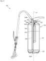
- the fire extinguisher 100 comprises a tank 120 and a cover 180.
- the tank 120 has a general shape of revolution about an axis A1 which, in a determined orientation of use of the fire extinguisher 100, is vertical relative to a horizontal plane, as illustrated in the figures or forms a few degrees of angle of inclination relative to the vertical. This determined orientation of use of the fire extinguisher 100 will serve as a reference for the remainder of the description.
- the tank 120 has a side wall 121, for example cylindrical of revolution about the axis A1, a bottom wall 122, for example convex downwards, to which this side wall 121 is connected in a lower zone of the tank 120, and a top wall 123 to which the side wall 120 is connected in an upper zone of the tank 120.
- These walls 120-123 are sealed and connected to each other in a gas- and liquid-tight manner so as to contain a fire extinguishing composition according to the invention 200 which fills the tank 120, for example over the majority of its height, the remainder of the tank 120 being filled with air at atmospheric pressure, the air being located in the upper zone of the tank 120.
- Said remainder of the tank 120 forms an expansion chamber 120' in the tank 120.
- top is defined relative to the axis A1 as towards the top wall 123 of the tank 120, while the term “bottom” is defined relative to the axis A1 as towards the bottom wall 122 of the tank 120.
- the top wall 123 is pierced, from side to side, with an orifice 123A for filling with fire extinguishing composition 200.
- This orifice 123A is advantageously delimited by an edge 123B of the top wall 123, which edge 123B is annular of revolution around the axis A1.
- the cover 180 is attached, for example in a removable manner, to the tank 120, to seal the orifice 123A in a sealed manner, and, as better shown in FIG.
- figure 5 comprises for this purpose a flat wall 181 having the general shape of a disk of revolution around the axis A1, which flat wall 181 has towards the bottom an annular groove, of revolution around the axis A1, suitable for receiving the edge 123B of the orifice 123A and for applying in a sealed manner to this edge 123B by by means of a seal not illustrated, when the cover 180 is fixed to the tank 120.
- This fixing is carried out for example, in a manner known per se, by bolting 124, preserving the sealing of the tank 120 by the flat wall 181 of the cover 180, on the top wall 123 around the orifice 123A of the tank 120.
- the flat wall 181 thus has a flat lower face 181A downwards, perpendicular to the axis A1, in which the groove is hollowed out.
- the lower face 181A connects to an unreferenced edge of the flat wall 181, which has for example a generally cylindrical shape of revolution around the axis A1 and connects the lower face 181A of the flat wall 181 to an upper face 181B of the flat wall 181.
- This upper face 181B located outside the tank 120 and consequently exposed to the ambient air, is flat and perpendicular to the axis A1 like the face 181A.
- a boss 182 advantageously made in one piece with the flat wall 181 and pierced, on one side of the axis A1, with a conduit 183 for the outlet of the fire extinguishing composition 200 contained in the tank 120, which conduit 183 has for this purpose an opening 183A opening into the lower face 181A of the flat wall 181 and an opening 183B in the boss 182.
- the extinguisher 100 further comprises control means 140 for striking a cover 134 of the flush bottle 130.
- the mouth 183A extends inside the tank 120, by a straight and sealed riser tube 160, having in the lower zone of the tank 120 a lower end 160A open downwards, at a bevel, and in the upper zone of the tank 120 an upper end 160B open upwards and connected in a sealed manner, around the mouth 183A, to the edge of the latter, for example by coaxial fitting of this upper end 160B into the mouth 183A or by coaxial screwing of this upper end 160B into the mouth 183A, suitably tapped for this purpose.
- the lower end 160A of the riser tube 160 is immersed in the fire extinguishing composition 200 for a wide range of orientations of the axis A1 relative to the vertical and even if only a bottom of the fire extinguishing composition 200 remains in the tank 120, at the end of use of the extinguisher 100, and the riser tube 160 can thus ensure even under such conditions the rise of the fire extinguishing composition 200 to the mouth 183A and the outlet 183B of the conduit 183.
- the conduit 183 is advantageously connected, in a sealed manner, to a flexible and sealed lance tube 190 provided with sealed closure means 191 and controlled and regulated opening, by action of the operator on a handle 191A, for example automatically returned to a state corresponding to the sealed closure of the tube 190, which closure means 191 are connected to a diffusion system 1 (or in other words an extinguishing nozzle 1), of the fire extinguishing composition 200 to be sprayed into the ambient air.
- a diffusion system 1 or in other words an extinguishing nozzle 1
- the diffusion system 1 may be or advantageously comprise an extinguishing nozzle 1 as described in the patent application.
- BE 1028003 A1 Such an extinguishing nozzle 1 is shown in the figure 6 , it comprises a mixing chamber 2, a ventilation chamber 3 and a foaming chamber 4, wherein said ventilation chamber 3 is coupled to said mixing chamber 2, and comprises a first hollow cylindrical body 5 comprising 4 air inlet holes 6, said air inlet holes 6 are arranged on the circumference and are directed into the first hollow cylindrical body 5.
- the foaming chamber 4 comprises a second hollow cylindrical body 7 having an axial length L and an inner diameter d, which foaming chamber 4 is coupled to said ventilation chamber 3.
- the ventilation chamber 3 and/or the foaming chamber 4 comprise a lattice (not visible), wherein said lattice is oriented in the radial plane of the inner cross-section of the ventilation chamber 3 and/or the foaming chamber 4, and in that the ratio between the axial length and the inner diameter L:d of the foaming chamber 4 is between 4:5 and 9:5.
- the cover 180 is hollowed out with another conduit 184 having both a mouth 184A and an outlet 184B in the lower face 181A of the flat wall 181.
- the conduit 184 has a first section 184C connected to the mouth 184A, a second section 184D, a third section 184E connected to the outlet 184B, and the second section 184D connecting the first section 184C to the third section 184E.
- the first section 184C extends coaxially upwards, beyond the connection of the second section 184D, by a bore 184F opening into the open air in the upper face 181B of the flat wall 181.
- the bore 184F defines by its connection with the first section 184C an annular shoulder.
- the bore 184F receives and guides in coaxial sliding a rod 141 of the percussion control means 140, which is sealed with respect to the bore 184F by a sealing gasket thus preserving the seal between the conduit 184 and the ambient air.
- this rod 141 Above the upper face 181B of the flat wall 181, this rod 141 has a convex upper end 141A, for example hemispherical, around which the boss 182 forms a yoke.
- the fire extinguisher comprises a handle 142.
- the handle 142 may be for carrying and/or, as will appear later, may be for activating the fire extinguisher 100 by percussion.
- This handle 142 extends in a cantilever manner, opposite the conduit 183 relative to the axis A1, and the handle 142 is for example pivotally mounted.
- the handle 142 is retained, by a removable pin 143 perpendicular to the axis A1 and bearing downwards on the flat wall 181, in an upper limit position illustrated in figures 1 And 2 , but when an operator wishes to put the extinguisher 100 into service, he removes the pin 143, which frees the handle 142 from tilting downwards relative to the boss 182.
- the handle 142 has, in a fixed manner, above the convex upper end 141A of the rod 141, a support surface 142A allowing, when the handle 142 is tilted by the operator, to apply to the rod 141, by means of its convex upper end 141A, a force forcing the rod 141 to slide downwards inside the bore 184F of the flat wall 181, from a high position which is illustrated in the figures and which it occupies.
- the bearing surface 142A is slightly spaced, upwards, from the convex upper end 141A of the rod 141 itself occupying its high position but, when the operator tilts the handle 142 downwards after having unpinned it, the latter comes to abut downwards by the bearing surface 142A on the upper end 141A of the rod 141 then causes a sliding movement of the latter downwards inside the bore 184F of the flat wall 181.
- the rod 141 has a widened lower end, in the form of a collar 141B, this collar 141B is shaped with respect to the connecting shoulder between the bore 184F and the first section 184C.
- the rod 141 is extended, integrally downwards, by a hollow needle 141C having an unreferenced external peripheral face with a diameter less than the respective diameters of the collar 141B and the first section 184C of the conduit 184.
- the rod 141 and the hollow needle 141C which may be made in one piece, constitute a striker, actuated by the handle 142, to controllably release a pressurized propellant gas 300 which is carbon dioxide and which is intended to expel the fire extinguishing composition 200 from the reservoir 120.
- a pressurized propellant gas 300 which is carbon dioxide and which is intended to expel the fire extinguishing composition 200 from the reservoir 120.
- This propellant gas 300 is contained in a flushing bottle 130 housed inside the tank 120 and connected in a sealed and integral manner, the flushing bottle 130 is preferably removable, at the mouth 184A of the first section 184C of the conduit 184, mounted for example by tapping.
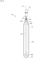
- the flushing bottle 130 may have a shape of revolution around an axis A2, optionally parallel to the axis A1.
- the flushing bottle 130 is delimited by a side wall 131, cylindrical of revolution around the axis A2, with an external diameter smaller, for example much smaller, than the internal diameter of the side wall 121 of the tank 120 so as to allow its introduction, and/or respectively its extraction, through the orifice 123A of the tank 120, together with the riser tube 160, when the cover 180 is put in place on the tank 120 and/or respectively when this cover 180 is dismantled for the purpose of maintenance or refilling the extinguisher 100 used.
- the wall 131 connects to a bottom wall 132, defining a lower zone of the flushing bottle 130 and having for example a convexity downwards, that is to say towards the bottom wall 122 of the tank 120 whereas, upwards, it connects to a top wall 133 defining an upper zone of the flushing bottle 130 with a convex shape.
- the bottom walls 132 and the top walls 133 are for example hemispherical or the bottom wall 132 is as shown in figure 4 .
- top is defined relative to the axis A2 as toward the top wall 133 of the flushing bottle 130
- bottom is defined relative to the axis A2 as toward the bottom wall 132 of the flushing bottle 130.
- the walls of the flushing bottle 130 are sealed and mutually connected in a sealed manner, except that the top wall 133 is connected to a tubular neck 133A, of revolution around the axis A2, projecting from its connection with the top wall 133, and opened by an outlet orifice 133B of the propellant gas 300.
- the outlet orifice 133B is sealed in a sealed manner by a sealed cover 134 of the flushing bottle 130, fixed in a sealed but preferably removably manner to the flushing bottle 130 around the outlet orifice 133B.
- the cap 134 is chosen such that it can be easily punctured by the needle 141C, on the one hand, but the cap 134 and its attachment are chosen so as to withstand the overpressure prevailing inside the flushing bottle 130 in comparison with the inside of the tank 120 before perforation under normal storage conditions of the extinguisher, on the other hand.
- the cap 134 is preferably turned to break first, that is to say preferentially at the flushing bottle 130, in the event of abnormally high overpressure therein, in order to avoid an explosion of the flushing bottle 130 in such a case.
- the propellant gas 300 escapes from the flush bottle 130 through the outlet orifice 133B towards the conduit 184 towards the space located inside the tank 120 to pressurize the fire extinguishing composition 200.
- This pressurization of the fire extinguishing composition 200 is facilitated by the use of a mixing tube 150 sealed at the outlet 184B of the conduit 184 connecting in a sealed manner, for example by fitting, into this conduit 184.
- the straight, sealed mixing tube 150 has a first end called the upper end 150A, open, directly attached to the outlet 184B and a second end said lower 150B sealed and which is preferably not immersed in the fire extinguishing composition 200.
- the mixing tube 150 has two lateral orifices 153A relative to the axis A1 to release the propellant gas 300 contained in the flush bottle 130 directly into the expansion chamber 120' of the tank 120.
- the side ports 153A are radial with respect to the axis A1, but as explained above, they could take any orientation along a secondary axis intersecting the axis A1.
- the two orifices 153A pass right through the wall of the mixing tube 150 in the same direction.
- a sealed dip tube 135 having an upper end 135A connected in a sealed manner to the neck 133A, for example by force fitting therein, and an open lower end 135B, for example cut at an angle, in the lower zone of the flushing bottle 130.
- the use of the extinguisher 100 is carried out in the following manner, the handle 142 being assumed to be initially immobilized by means of the pin 143 in its high position in which the support surface 142A does not stress the rod 141, itself in the high position, the cover 134 being intact and sealingly closing the flushing bottle 130; all communication is initially assumed to be closed between the flexible lance tube 190 and the diffusion system or diffuser 1, by the sealing means 191.
- the contents of the flush bottle 130 are then released through the radial orifices 153A to be released into the expansion chamber 120' of the tank 120.
- the expansion chamber 120' is then pressurized by the propellant gas 300 from the flush bottle 130 so that the pressure contained in this expansion chamber 120' in turn pressurizes the contents of the tank 120, thus promoting the rise of the fire extinguishing composition 200 through the riser tube 160.
- the operator can then, by acting on the handle 191A, release at will the fire extinguishing composition 200 which is dispersed thanks to the diffuser 1.
- the extinguisher 100 When the extinguisher 100 is empty or practically empty of the fire extinguishing composition 200, it can be recharged by removing the cover 180, filling with said fire extinguishing composition through the orifice 123A, replacing the assembly formed by the flushing bottle 130, then empty, and the perforated cover 134, by means of a new flushing bottle 130 containing the desired quantity of pressurized propellant gas 300, sealed by a new cover 134 retained at the orifice 133B of the flushing bottle 130, and reassembling the cover 180 thus re-equipped.
- Tests were carried out with a fire extinguishing composition according to the invention and a comparative fire extinguishing composition using the technical reference NTA 8133 (November 2021) which describes the performance requirements, test methods and marking of the suitability for extinguishing lithium-ion battery fires.
- the fire extinguishing composition according to the invention comprised a flame retardant, anionic and amphoteric surfactants, foam and thermal stabilizers, and an organic solvent selected from glycols except glycols in polymer form and glycol ethers in amounts as described above.
- the comparative fire extinguishing composition was a commercial fire extinguishing composition recommended for use in extinguishing lithium-ion battery fires.
- the fire extinguisher used for these tests was the extinguisher according to the invention shown in the Figures 1 to 6 and which was described above.
- the hunting bottle contained 60 g of carbon dioxide (propellant gas).
- the lithium-ion battery for these tests had a power of 600 Wh. This corresponds to a lithium-ion battery for a mountain bike. It consisted of 6 sets of 4 flat cell batteries.
- the cell in the centre of the lithium-ion battery was charged beyond 100% so that after 7 to 9 minutes it burst and flames appeared. This cell transmitted heat to the other adjacent cells which in turn burst.
- test was conclusive when at least one cell was intact. To do this, it was checked that its voltage was at least 3.7V. In addition, it was necessary for 2 tests out of a series of 3 tests to be successful to validate the test protocol according to the NTA 8133 standard.
- the test was conclusive with the fire extinguishing composition according to the invention but not with the comparative fire extinguishing composition.
Landscapes
- Chemical & Material Sciences (AREA)
- Chemical Kinetics & Catalysis (AREA)
- General Chemical & Material Sciences (AREA)
- Business, Economics & Management (AREA)
- Emergency Management (AREA)
- Engineering & Computer Science (AREA)
- Manufacturing & Machinery (AREA)
- Electrochemistry (AREA)
- Health & Medical Sciences (AREA)
- Public Health (AREA)
- Fire-Extinguishing Compositions (AREA)
Applications Claiming Priority (1)
| Application Number | Priority Date | Filing Date | Title |
|---|---|---|---|
| FR2307807A FR3151222A1 (fr) | 2023-07-20 | 2023-07-20 | Composition d’extinction d’incendie d’accumulateur lithium-ion et extincteur comprenant une telle composition |
Publications (1)
| Publication Number | Publication Date |
|---|---|
| EP4494718A1 true EP4494718A1 (de) | 2025-01-22 |
Family
ID=88505331
Family Applications (1)
| Application Number | Title | Priority Date | Filing Date |
|---|---|---|---|
| EP24189532.5A Withdrawn EP4494718A1 (de) | 2023-07-20 | 2024-07-18 | Feuerlöschzusammensetzung für lithium-ionen-akkumulator und feuerlöscher mit einer solchen zusammensetzung |
Country Status (2)
| Country | Link |
|---|---|
| EP (1) | EP4494718A1 (de) |
| FR (1) | FR3151222A1 (de) |
Citations (4)
| Publication number | Priority date | Publication date | Assignee | Title |
|---|---|---|---|---|
| EP0792665A1 (de) * | 1996-02-27 | 1997-09-03 | Extincteurs Andrieu | Flüssigkeitszerstäubungsfeuerlöscher |
| BE1028003A1 (fr) | 2020-02-10 | 2021-08-17 | Uniteq S A | Buse d'extinction d'incendie et extincteur |
| EP4032590A1 (de) * | 2021-01-22 | 2022-07-27 | Uniteq S.A. | Feuerlöschformulierung mit verbesserter schaumbildung |
| AU2021218099A1 (en) * | 2021-08-18 | 2023-03-09 | Optim Fire Essentials Pty. Ltd. | Composition, container, system and methods |
-
2023
- 2023-07-20 FR FR2307807A patent/FR3151222A1/fr active Pending
-
2024
- 2024-07-18 EP EP24189532.5A patent/EP4494718A1/de not_active Withdrawn
Patent Citations (4)
| Publication number | Priority date | Publication date | Assignee | Title |
|---|---|---|---|---|
| EP0792665A1 (de) * | 1996-02-27 | 1997-09-03 | Extincteurs Andrieu | Flüssigkeitszerstäubungsfeuerlöscher |
| BE1028003A1 (fr) | 2020-02-10 | 2021-08-17 | Uniteq S A | Buse d'extinction d'incendie et extincteur |
| EP4032590A1 (de) * | 2021-01-22 | 2022-07-27 | Uniteq S.A. | Feuerlöschformulierung mit verbesserter schaumbildung |
| AU2021218099A1 (en) * | 2021-08-18 | 2023-03-09 | Optim Fire Essentials Pty. Ltd. | Composition, container, system and methods |
Also Published As
| Publication number | Publication date |
|---|---|
| FR3151222A1 (fr) | 2025-01-24 |
Similar Documents
| Publication | Publication Date | Title |
|---|---|---|
| EP1168479B1 (de) | Batterie von elektrochemischen Generatoren mit Sicherheitsvorrichtung | |
| KR102737048B1 (ko) | 침윤소화약제에 의해 신속 화재진압이 가능한 배터리충전 시스템 | |
| CA2589873C (fr) | Dispositif pour augmenter l'efficacite du gaz de pressurisation dans une bouteille d'extincteur | |
| FR2704981A1 (fr) | Batterie d'accumulateurs à haute température et batterie d'accumulateurs à haute température protégée. | |
| FR2763249A1 (fr) | Dispositif d'extinction de flammes | |
| Tianwei et al. | Synergistic inhibition effect on lithium-ion batteries during thermal runaway by N2-twin-fluid liquid mist | |
| EP2683449B1 (de) | Vorrichtung zur brandlöschung | |
| EP1961458A2 (de) | Feuerlöscher und seine Verwendung | |
| EP4494718A1 (de) | Feuerlöschzusammensetzung für lithium-ionen-akkumulator und feuerlöscher mit einer solchen zusammensetzung | |
| EP4420740B1 (de) | Verbesserter feuerlöscher zur dispersion eines fluorfreien löschmittels | |
| EP0018883A1 (de) | Verfahren zur Verringerung der Entzündungs- und Explosionsgefahr infolge des Zerfalls von Hochdruckäthylen und Vorrichtung zur Durchführung des Verfahrens | |
| EP1376720B1 (de) | Batterie mit verbesserter Sicherheit | |
| EP0461020A1 (de) | Zerbrechliche Patrone für Feuerlöschzusatzstoffe in Wasserfeuerlöschern, die auf Gebrauchsmomente durch ein Gas unter Druck gesetzt werden | |
| BE1031782B1 (fr) | Formulation d'extinction d'incendie sans fluor pour des systemes de stockage et de conversion d'energie electrochimique | |
| CN113384832A (zh) | 一种车载森林消防固化泡沫灭火装置及火焰阻隔方法 | |
| EP1902757A1 (de) | Antriebsvorrichtung für ein in einem Hohlraum enthaltenem Mittel | |
| FR2888124A1 (fr) | Extincteur a brouillard de liquide et son utilisation | |
| EP3094916A1 (de) | Thermisches schutzsystem für einen kryogenen behälter eines raumfahrzeuges | |
| EP2162323B1 (de) | Waschflüssigkeitstank für ein automobil | |
| EP0792665B1 (de) | Flüssigkeitszerstäubungsfeuerlöscher | |
| FR3118885A1 (fr) | Dispositif d’extinction d’un feu | |
| FR2508238A1 (fr) | Piles electrochimiques et procede de remplissage de ces piles | |
| KR102845193B1 (ko) | 가스 하이드레이트를 적용한 소화기 | |
| EP0965364A1 (de) | Schlauch für Feuerlöscher | |
| KR102722405B1 (ko) | 침윤강화소화액을 이용한 전기차량의 차량배터리 화재 소화장치 |
Legal Events
| Date | Code | Title | Description |
|---|---|---|---|
| PUAI | Public reference made under article 153(3) epc to a published international application that has entered the european phase |
Free format text: ORIGINAL CODE: 0009012 |
|
| STAA | Information on the status of an ep patent application or granted ep patent |
Free format text: STATUS: THE APPLICATION HAS BEEN PUBLISHED |
|
| AK | Designated contracting states |
Kind code of ref document: A1 Designated state(s): AL AT BE BG CH CY CZ DE DK EE ES FI FR GB GR HR HU IE IS IT LI LT LU LV MC ME MK MT NL NO PL PT RO RS SE SI SK SM TR |
|
| STAA | Information on the status of an ep patent application or granted ep patent |
Free format text: STATUS: THE APPLICATION IS DEEMED TO BE WITHDRAWN |
|
| 18D | Application deemed to be withdrawn |
Effective date: 20250723 |