EP4494528A1 - Verschlussvorrichtung für einen flüssigkeitsbehälter - Google Patents
Verschlussvorrichtung für einen flüssigkeitsbehälter Download PDFInfo
- Publication number
- EP4494528A1 EP4494528A1 EP24187647.3A EP24187647A EP4494528A1 EP 4494528 A1 EP4494528 A1 EP 4494528A1 EP 24187647 A EP24187647 A EP 24187647A EP 4494528 A1 EP4494528 A1 EP 4494528A1
- Authority
- EP
- European Patent Office
- Prior art keywords
- container
- membrane
- main body
- lower body
- liquids
- Prior art date
- Legal status (The legal status is an assumption and is not a legal conclusion. Google has not performed a legal analysis and makes no representation as to the accuracy of the status listed.)
- Granted
Links
Images


Classifications
-
- B—PERFORMING OPERATIONS; TRANSPORTING
- B65—CONVEYING; PACKING; STORING; HANDLING THIN OR FILAMENTARY MATERIAL
- B65D—CONTAINERS FOR STORAGE OR TRANSPORT OF ARTICLES OR MATERIALS, e.g. BAGS, BARRELS, BOTTLES, BOXES, CANS, CARTONS, CRATES, DRUMS, JARS, TANKS, HOPPERS, FORWARDING CONTAINERS; ACCESSORIES, CLOSURES, OR FITTINGS THEREFOR; PACKAGING ELEMENTS; PACKAGES
- B65D41/00—Caps, e.g. crown caps or crown seals, i.e. members having parts arranged for engagement with the external periphery of a neck or wall defining a pouring opening or discharge aperture; Protective cap-like covers for closure members, e.g. decorative covers of metal foil or paper
- B65D41/02—Caps or cap-like covers without lines of weakness, tearing strips, tags, or like opening or removal devices
- B65D41/04—Threaded or like caps or cap-like covers secured by rotation
- B65D41/0485—Threaded or like caps or cap-like covers secured by rotation with means specially adapted for facilitating the operation of opening or closing
-
- B—PERFORMING OPERATIONS; TRANSPORTING
- B65—CONVEYING; PACKING; STORING; HANDLING THIN OR FILAMENTARY MATERIAL
- B65D—CONTAINERS FOR STORAGE OR TRANSPORT OF ARTICLES OR MATERIALS, e.g. BAGS, BARRELS, BOTTLES, BOXES, CANS, CARTONS, CRATES, DRUMS, JARS, TANKS, HOPPERS, FORWARDING CONTAINERS; ACCESSORIES, CLOSURES, OR FITTINGS THEREFOR; PACKAGING ELEMENTS; PACKAGES
- B65D47/00—Closures with filling and discharging, or with discharging, devices
- B65D47/04—Closures with discharging devices other than pumps
- B65D47/06—Closures with discharging devices other than pumps with pouring spouts or tubes; with discharge nozzles or passages
-
- A—HUMAN NECESSITIES
- A47—FURNITURE; DOMESTIC ARTICLES OR APPLIANCES; COFFEE MILLS; SPICE MILLS; SUCTION CLEANERS IN GENERAL
- A47G—HOUSEHOLD OR TABLE EQUIPMENT
- A47G19/00—Table service
- A47G19/22—Drinking vessels or saucers used for table service
- A47G19/2205—Drinking glasses or vessels
- A47G19/2266—Means for facilitating drinking, e.g. for infants or invalids
- A47G19/2272—Means for facilitating drinking, e.g. for infants or invalids from drinking glasses or cups comprising lids or covers
-
- B—PERFORMING OPERATIONS; TRANSPORTING
- B65—CONVEYING; PACKING; STORING; HANDLING THIN OR FILAMENTARY MATERIAL
- B65D—CONTAINERS FOR STORAGE OR TRANSPORT OF ARTICLES OR MATERIALS, e.g. BAGS, BARRELS, BOTTLES, BOXES, CANS, CARTONS, CRATES, DRUMS, JARS, TANKS, HOPPERS, FORWARDING CONTAINERS; ACCESSORIES, CLOSURES, OR FITTINGS THEREFOR; PACKAGING ELEMENTS; PACKAGES
- B65D41/00—Caps, e.g. crown caps or crown seals, i.e. members having parts arranged for engagement with the external periphery of a neck or wall defining a pouring opening or discharge aperture; Protective cap-like covers for closure members, e.g. decorative covers of metal foil or paper
- B65D41/02—Caps or cap-like covers without lines of weakness, tearing strips, tags, or like opening or removal devices
- B65D41/04—Threaded or like caps or cap-like covers secured by rotation
- B65D41/0492—Threaded or like caps or cap-like covers secured by rotation formed by several elements connected together
-
- B—PERFORMING OPERATIONS; TRANSPORTING
- B65—CONVEYING; PACKING; STORING; HANDLING THIN OR FILAMENTARY MATERIAL
- B65D—CONTAINERS FOR STORAGE OR TRANSPORT OF ARTICLES OR MATERIALS, e.g. BAGS, BARRELS, BOTTLES, BOXES, CANS, CARTONS, CRATES, DRUMS, JARS, TANKS, HOPPERS, FORWARDING CONTAINERS; ACCESSORIES, CLOSURES, OR FITTINGS THEREFOR; PACKAGING ELEMENTS; PACKAGES
- B65D47/00—Closures with filling and discharging, or with discharging, devices
- B65D47/04—Closures with discharging devices other than pumps
- B65D47/20—Closures with discharging devices other than pumps comprising hand-operated members for controlling discharge
- B65D47/2018—Closures with discharging devices other than pumps comprising hand-operated members for controlling discharge comprising a valve or like element which is opened or closed by deformation of the container or closure
-
- B—PERFORMING OPERATIONS; TRANSPORTING
- B65—CONVEYING; PACKING; STORING; HANDLING THIN OR FILAMENTARY MATERIAL
- B65D—CONTAINERS FOR STORAGE OR TRANSPORT OF ARTICLES OR MATERIALS, e.g. BAGS, BARRELS, BOTTLES, BOXES, CANS, CARTONS, CRATES, DRUMS, JARS, TANKS, HOPPERS, FORWARDING CONTAINERS; ACCESSORIES, CLOSURES, OR FITTINGS THEREFOR; PACKAGING ELEMENTS; PACKAGES
- B65D47/00—Closures with filling and discharging, or with discharging, devices
- B65D47/04—Closures with discharging devices other than pumps
- B65D47/20—Closures with discharging devices other than pumps comprising hand-operated members for controlling discharge
- B65D47/24—Closures with discharging devices other than pumps comprising hand-operated members for controlling discharge with poppet valves or lift valves, i.e. valves opening or closing a passageway by a relative motion substantially perpendicular to the plane of the seat
-
- B—PERFORMING OPERATIONS; TRANSPORTING
- B65—CONVEYING; PACKING; STORING; HANDLING THIN OR FILAMENTARY MATERIAL
- B65D—CONTAINERS FOR STORAGE OR TRANSPORT OF ARTICLES OR MATERIALS, e.g. BAGS, BARRELS, BOTTLES, BOXES, CANS, CARTONS, CRATES, DRUMS, JARS, TANKS, HOPPERS, FORWARDING CONTAINERS; ACCESSORIES, CLOSURES, OR FITTINGS THEREFOR; PACKAGING ELEMENTS; PACKAGES
- B65D51/00—Closures not otherwise provided for
- B65D51/16—Closures not otherwise provided for with means for venting air or gas
- B65D51/1633—Closures not otherwise provided for with means for venting air or gas whereby venting occurs by automatic opening of the closure, container or other element
- B65D51/1644—Closures not otherwise provided for with means for venting air or gas whereby venting occurs by automatic opening of the closure, container or other element the element being a valve
- B65D51/165—Closures not otherwise provided for with means for venting air or gas whereby venting occurs by automatic opening of the closure, container or other element the element being a valve formed by a slit or narrow opening
-
- B—PERFORMING OPERATIONS; TRANSPORTING
- B65—CONVEYING; PACKING; STORING; HANDLING THIN OR FILAMENTARY MATERIAL
- B65D—CONTAINERS FOR STORAGE OR TRANSPORT OF ARTICLES OR MATERIALS, e.g. BAGS, BARRELS, BOTTLES, BOXES, CANS, CARTONS, CRATES, DRUMS, JARS, TANKS, HOPPERS, FORWARDING CONTAINERS; ACCESSORIES, CLOSURES, OR FITTINGS THEREFOR; PACKAGING ELEMENTS; PACKAGES
- B65D53/00—Sealing or packing elements; Sealings formed by liquid or plastics material
Definitions
- the present invention relates to a closure device for containers adapted to contain liquids.
- a closure device for containers adapted to contain liquids.
- Such a device finds particular application in the field related to the closures of containers for learning, including, for example, glasses or cups, intended for use by children or persons with disabilities, to avoid creating splashes of the liquid contained in the container during use or during situations in which the container might be shaken.
- closure devices for liquid containers are known that allow drinking from the container without causing splashing and without the need to remove and reapply hard-to-use caps.
- closure device comprises a gasket adapted to abut an edge of a valve element, and a splash guard having a central cavity adapted to receive and constrain to the gasket.
- the document GB 2461005 A shows a further example of a device for drinking from a container capable of preventing the formation of splashes.
- a device for drinking from a container capable of preventing the formation of splashes.
- such a device comprises a support element, a gasket insertable in the support element and a retaining element adapted to retain the gasket in place against the support element.
- closure devices are disclosed in the prior art document EP 3934488 A1 , in which a gasket and a closure body for accommodating the gasket are shown.
- the closure body comprises passages for liquids and a portion adapted to abut with a lip of the gasket to allow the retention thereof.
- a further example of a closure device is shown in the prior art document EP 1632437 A1 , in which a tubular portion is movable with respect to a fixed portion to switch between an opening configuration and a closing configuration, respectively to allow and block the exit of liquids.
- the known closure devices require moulding different components having elaborate shapes, and therefore difficult to manufacture, necessary to carry out all the functions necessary to allow a child or a person with a disability to drink from the container, avoiding the exit of splashes and simultaneously ensuring a good seal between the device and the container.
- the technical task underlying the present invention is to propose a closure device for containers for liquids which allows to overcome the drawbacks of the prior art mentioned above.
- the object of the present invention is to provide a closure device for containers which is simplified and easy to manufacture and assemble by the user, without losing functionality, so that a child or a person with a disability can drink from the container without causing unwanted spills of liquid or without the need to screw and unscrew caps every time it is used.
- a further object of the present invention is to find an alternative solution to the solutions of the state of the art, which allows to make it easier to clean the components.
- the present invention has the advantage of obtaining, in a simple and effective manner, a closure device consisting of simple geometric shapes, easily reproducible and lacking portions or recesses which are difficult to access.
- the closure device of the present invention comprises a membrane adapted to elastically deform to pass between a resting configuration and a working configuration. It is thereby possible to make the device in a resting configuration, easy to obtain, and to use the device in the working configuration, which would be difficult to obtain with the same production technique.
- the closure device of the present invention allows to unify the main functions of a closure device in the membrane, greatly reducing the structural and production complexity.
- the present invention has the further advantage of allowing an adequate and practical cleaning of the components.
- the membrane in the resting configuration the membrane can be disengaged from the container and, thanks to the simple geometry lacking narrow recesses, it can be adequately cleaned.
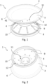
- a closure device for a container for liquids is denoted with 1. Instead, 100 indicates the container 100 for liquids, and in particular a container for drinking liquids, which comprises an opening 105 delimited by an opening edge 110.
- the device 1 of the present invention comprises an elastically deformable membrane 2, which has a main body 3 adapted to be placed to close the opening 105 of the container 100.
- the main body 3 of the membrane 2 comprises a connection portion 4 and an impervious main wall 5, protruding from the connection wall 4 and has a free edge 6 opposite the connection portion 4.
- connection portion 4 has one or more openings 41 to allow the passage of air between an environment inside the container and an environment outside it. It should be noted that such openings do not allow the passage of liquids.
- the openings 41 can be shaped as notches in the connection portion 4. Accordingly, the main body 3 as a whole is preferably impervious with respect to liquids.
- the membrane 2 further has a lower body 8 projecting from the connection portion 4 of the main body 3 and comprising a retention flange 10 adapted to engage with the opening edge 110 of the container 100 to constrain the membrane 2 to the container 100.
- the lower body 8 further comprises a plurality of openings 9 for the passage of liquids.
- the openings 9 have a circular or oval shape.
- the openings 9 are arranged uniformly on the lower body 8.
- the openings 9 can be circumferentially distributed along the lower body 8, and optionally some openings 9 can be radially spaced from each other.
- the lower body 8 has a plurality of grooves, for example radial grooves, in which one or more openings 9 are positioned.
- the device 1 comprises a collar 20 couplable to the container 100.
- the collar 20 is disclosed as a component of the device 1, but it can also be understood as a component of the container 100.
- the collar 20 comprises a side wall 21 delimiting a cavity 24 adapted to receive the membrane 2. Still preferably, the collar 20 comprises an end portion 22 having an upper edge 23.
- the side wall 21 of the collar 20 is adapted to retain the retaining flange 10 against the edge 110 of the container 100 and, more preferably, to retain the retaining flange 10 between the edge 110 of the container 100 and the side wall 21 itself.
- the side wall 21 has a thread adapted to couple with a respective thread of the edge 110 of the container 100.
- the retaining flange 10 is adapted to be inserted between the thread and the upper edge 23 of the collar 20.
- the free edge 6 of the membrane 2 is adapted to abut with the end portion 22 of the collar 20 and, more preferably, with the upper edge 23 of the end portion 22.
- the free edge 6 is therefore adapted to seal the opening 105 of the container 100, engaging for example the opening edge 110 or, alternatively, the end portion 22 of the collar 20. Furthermore, the free edge 6 is configured to elastically deform, when subjected to a suction action of a user, to put an environment inside the container 100 in fluid communication with an environment outside it. In particular, the free edge 6 is configured to allow the exit of liquids passed through the openings 9 of the lower body 8. Such a deformation, of known type, involves a local lifting of the free edge 6 from the opening edge 110 and/or from the end portion 22 of the collar 20.
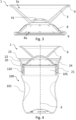
- the membrane 2 is configured to elastically switch between a resting configuration and a working configuration.
- the resting configuration is functional to the construction and assembly of the membrane 2, but in such a configuration the membrane 2 is not adapted to seal the opening 105 of the container 100.
- the free edge 6 of the membrane 2 is lifted with respect to the edge 110 of the container 100 and/or with respect to the end portion 22, and in particular with respect to the upper edge 23, of the collar 20.
- the free edge 6 of the main body 3 is spaced from the retaining flange 10 of the lower body 8.
- the free edge 6 of the main body 3 is close to the retaining flange 10 of the lower body, so as to seal the opening 105 of the container, and/or the cavity of the collar 20, resting on the edge of the container 110 and/or on the end portion 22, and in particular on the upper edge 23, of the collar 20.
- the membrane 2 is configured to elastically switch from the resting configuration to the working configuration upon the receipt of a pressure at the connection portion 4 of the main body 3. Therefore, the user is capable of coupling the membrane 2 to the container 100 in the resting configuration, and then bringing the membrane from the resting configuration to the working configuration by pressing at the connection portion 4.
- the main body 3 and the lower body 8 of the membrane 2 each have a respective concavity 3a, 8a, which face in opposite orientations in the resting configuration and in the same orientation in the working configuration.
- the main body 3 and the lower body 8 both have a concave shape, closed at the connection portion 4 and having an opening opposite the connection portion 4.
- the main body 3 and the lower body 8 have a hollow truncoconical shape.
- the main body 3 and the lower body 8 define an X-shape in section with the respective concavities 3a, 8a facing opposite orientations.
- the membrane 2 of the closing device of the present invention has a simple and easily reproducible geometry in the resting configuration. It should therefore be noted that such a geometry allows an accurate and practical cleaning of the device and, in particular, of the membrane.
- the main body 3 in the working configuration is at least partially housed in the concavity 8a of the lower body 8.
- the lower body 8 in the passage between the resting configuration and the working configuration is configured to elastically deform, inverting the orientation of the respective concavity 8a by folding at a first folding line 11 which extends between the connection portion 4 of the main body 3 and the lower body 8.
- the membrane 2 has a second folding line 12 along the retaining flange 10 for switching between the resting configuration and the working configuration.
- first folding line 11 and/or the second folding line 12 are defined by grooves comprised respectively in the connection portion 4 and/or in the retaining flange 10.
- connection portion 4 and/or the retaining flange 10 are shaped to define weakening portions at the first 11 and/or the second folding line 12, respectively.
- weakening portions are adapted to favour the deformation of the material which constitutes the membrane 2 along the weakening portions.
- the lower body is adapted to deform between the connection portion 4 and the retaining flange 10 to invert the orientation of the respective concavity 8a. Therefore, the retaining flange 10 and the connection portion 4 remain at least partly undeformed in switching between the resting configuration and the working configuration.
- the membrane 2 in the working configuration identifies a suction chamber 7 between the main wall 5 of the main body 3 and the lower body 8.
- the suction chamber 7 is adapted to receive liquids from the container 100 through the plurality of openings 9 of the lower body 8 and to temporarily retain the liquids.
- the free edge 6 in the working configuration is adapted to seal the suction chamber 7 to retain the liquids.
- the free edge is adapted to elastically deform when subjected to the suction action of the user to place the suction chamber 7 in fluid communication with the environment outside the container 100 and thus allow the exit of liquid from the suction chamber 7.
- the suction chamber 7 is identified between the main wall 5 of the main body 3, the lower body 8 and the side wall 21 of the collar 20.
- the membrane 2 is made in a single piece.
- the membrane 2 can be made by moulding, preferably injection moulding, in particular when in the resting configuration.
- the shape of the membrane 2 in the working configuration would not allow its moulding.
- the membrane 2 can be made overmolded to the collar.
- the membrane 2 is made of polymeric material and, more preferably, of silicone.
- the membrane 2 has a shape which is optimised and simple to make, defined by simple geometric figures obtainable by moulding. It is thereby possible to speed up and simplify the membrane manufacturing process and simplify the assembly process on a container. In fact, as previously anticipated, making the membrane in a single piece according to a simple geometry makes cleaning the device more practical.
- a further object of the present invention is a container 100 for liquids comprising a container body 101 adapted to receive liquids and having a free opening edge 110 and an opening 105 delimited by the edge 110 to allow the passage of liquids along the main direction X.
- the container 100 subj ect-matter of the present invention further comprises a closure device 1 according to the present description coupled to the edge 110.
- the coupling between the device 1 and the opening edge 110 of the container 100 occurs by means of reversible connection between respective threads of the collar 20 of the device 1 and the edge 110 of the container.
- the retaining flange 10 of the membrane 2 of the device 1 can comprise a respective seat adapted to internally receive at least in part the edge 110 of the container for coupling thereto.
- the container 100 can have a seat adapted to receive and be constrained to the retaining flange 10 of the membrane 2 of the device 1.
Landscapes
- Engineering & Computer Science (AREA)
- Mechanical Engineering (AREA)
- Health & Medical Sciences (AREA)
- General Health & Medical Sciences (AREA)
- Pediatric Medicine (AREA)
- Closures For Containers (AREA)
Applications Claiming Priority (1)
| Application Number | Priority Date | Filing Date | Title |
|---|---|---|---|
| IT102023000015297A IT202300015297A1 (it) | 2023-07-20 | 2023-07-20 | Dispositivo di chiusura per un contenitore per liquidi |
Publications (2)
| Publication Number | Publication Date |
|---|---|
| EP4494528A1 true EP4494528A1 (de) | 2025-01-22 |
| EP4494528B1 EP4494528B1 (de) | 2026-02-25 |
Family
ID=88505246
Family Applications (1)
| Application Number | Title | Priority Date | Filing Date |
|---|---|---|---|
| EP24187647.3A Active EP4494528B1 (de) | 2023-07-20 | 2024-07-10 | Verschlussvorrichtung für einen flüssigkeitsbehälter |
Country Status (4)
| Country | Link |
|---|---|
| US (1) | US20250026540A1 (de) |
| EP (1) | EP4494528B1 (de) |
| CN (1) | CN119329897A (de) |
| IT (1) | IT202300015297A1 (de) |
Citations (4)
| Publication number | Priority date | Publication date | Assignee | Title |
|---|---|---|---|---|
| EP1632437A1 (de) | 2004-09-01 | 2006-03-08 | Carbonite Corporation | Zapfen für Getränkebehälter |
| GB2461005A (en) | 2007-03-10 | 2009-12-23 | And Design Ltd | Valve arrangement |
| EP2265152A1 (de) | 2008-04-07 | 2010-12-29 | Gunnar Berg | Trinkbechervorrichtung |
| EP3934488A1 (de) | 2019-03-05 | 2022-01-12 | Koninklijke Philips N.V. | Abdeckung einer trinkvorrichtung |
Family Cites Families (4)
| Publication number | Priority date | Publication date | Assignee | Title |
|---|---|---|---|---|
| US4917267A (en) * | 1986-11-12 | 1990-04-17 | Laverdure Roland J A | Self-closing valve with tamper evident lip seal tab for liquids, pastes or solids |
| NO20050494D0 (no) * | 2005-01-28 | 2005-01-28 | Aasmund Torvik | Brystpumpe for pumping av melk. |
| US20110186573A1 (en) * | 2010-02-04 | 2011-08-04 | Trudeau Corporation 1889 Inc. | Cap for a container |
| CN111655087A (zh) * | 2017-12-04 | 2020-09-11 | 玛帕有限公司 | 饮用容器的饮用附接件和具有此附接件的饮用容器 |
-
2023
- 2023-07-20 IT IT102023000015297A patent/IT202300015297A1/it unknown
-
2024
- 2024-07-10 EP EP24187647.3A patent/EP4494528B1/de active Active
- 2024-07-16 US US18/773,815 patent/US20250026540A1/en active Pending
- 2024-07-17 CN CN202410957520.5A patent/CN119329897A/zh active Pending
Patent Citations (4)
| Publication number | Priority date | Publication date | Assignee | Title |
|---|---|---|---|---|
| EP1632437A1 (de) | 2004-09-01 | 2006-03-08 | Carbonite Corporation | Zapfen für Getränkebehälter |
| GB2461005A (en) | 2007-03-10 | 2009-12-23 | And Design Ltd | Valve arrangement |
| EP2265152A1 (de) | 2008-04-07 | 2010-12-29 | Gunnar Berg | Trinkbechervorrichtung |
| EP3934488A1 (de) | 2019-03-05 | 2022-01-12 | Koninklijke Philips N.V. | Abdeckung einer trinkvorrichtung |
Also Published As
| Publication number | Publication date |
|---|---|
| CN119329897A (zh) | 2025-01-21 |
| IT202300015297A1 (it) | 2025-01-20 |
| US20250026540A1 (en) | 2025-01-23 |
| EP4494528B1 (de) | 2026-02-25 |
Similar Documents
| Publication | Publication Date | Title |
|---|---|---|
| CA2879752C (en) | Drinking container with removable lid | |
| CA2297211C (en) | Valves for packaging containers | |
| US4793501A (en) | Water tight hinge closure | |
| US4671421A (en) | Plastic container | |
| EP1841662B1 (de) | Lecksicherer trinkbecher | |
| EP3266352A1 (de) | Verschlussvorrichtung für behältern zur aufnahme von flüssigkeiten | |
| JP2013538068A (ja) | 飲用容器 | |
| KR101701252B1 (ko) | 음료 공급 장치 어셈블리 | |
| JPS60110649A (ja) | 飲用容器 | |
| CA2411402A1 (en) | Synthetic resin bottle cap unit | |
| EP4228977B1 (de) | Beutel mit ausguss, verschlussanordnung und herstellungsverfahren | |
| US6318422B2 (en) | Funnel for viscous liquids | |
| EP3445312B1 (de) | Flaschenanordnung und ventilanordnung | |
| EP4494528A1 (de) | Verschlussvorrichtung für einen flüssigkeitsbehälter | |
| KR20090087887A (ko) | 캔의 폐쇄 구조 | |
| WO2004039688A9 (en) | Disposable leak proof child drinking cup | |
| CA2615851C (en) | Drinking container | |
| WO1997009917A1 (en) | Self-emptying plug | |
| JPH0223569Y2 (de) | ||
| JP4215144B2 (ja) | シールされた注出孔付きの合成樹脂製中栓 | |
| WO2003105635A1 (en) | A valve | |
| JPH0138050Y2 (de) | ||
| NL1020348C2 (nl) | Houder met afsluiter. | |
| DK160701B (da) | Beholderlaag | |
| JP2004331133A (ja) | 気密キャップ |
Legal Events
| Date | Code | Title | Description |
|---|---|---|---|
| PUAI | Public reference made under article 153(3) epc to a published international application that has entered the european phase |
Free format text: ORIGINAL CODE: 0009012 |
|
| STAA | Information on the status of an ep patent application or granted ep patent |
Free format text: STATUS: THE APPLICATION HAS BEEN PUBLISHED |
|
| AK | Designated contracting states |
Kind code of ref document: A1 Designated state(s): AL AT BE BG CH CY CZ DE DK EE ES FI FR GB GR HR HU IE IS IT LI LT LU LV MC ME MK MT NL NO PL PT RO RS SE SI SK SM TR |
|
| STAA | Information on the status of an ep patent application or granted ep patent |
Free format text: STATUS: REQUEST FOR EXAMINATION WAS MADE |
|
| 17P | Request for examination filed |
Effective date: 20250618 |
|
| REG | Reference to a national code |
Ref country code: DE Ref legal event code: R079 Free format text: PREVIOUS MAIN CLASS: A47G0019220000 Ipc: B65D0051160000 Ref country code: DE Ref legal event code: R079 Ref document number: 602024002789 Country of ref document: DE Free format text: PREVIOUS MAIN CLASS: A47G0019220000 Ipc: B65D0051160000 |
|
| GRAP | Despatch of communication of intention to grant a patent |
Free format text: ORIGINAL CODE: EPIDOSNIGR1 |
|
| STAA | Information on the status of an ep patent application or granted ep patent |
Free format text: STATUS: GRANT OF PATENT IS INTENDED |
|
| RIC1 | Information provided on ipc code assigned before grant |
Ipc: B65D 51/16 20060101AFI20250919BHEP Ipc: B65D 47/24 20060101ALI20250919BHEP Ipc: A47G 19/22 20060101ALI20250919BHEP |
|
| INTG | Intention to grant announced |
Effective date: 20251014 |
|
| GRAS | Grant fee paid |
Free format text: ORIGINAL CODE: EPIDOSNIGR3 |
|
| GRAA | (expected) grant |
Free format text: ORIGINAL CODE: 0009210 |
|
| STAA | Information on the status of an ep patent application or granted ep patent |
Free format text: STATUS: THE PATENT HAS BEEN GRANTED |
|
| AK | Designated contracting states |
Kind code of ref document: B1 Designated state(s): AL AT BE BG CH CY CZ DE DK EE ES FI FR GB GR HR HU IE IS IT LI LT LU LV MC ME MK MT NL NO PL PT RO RS SE SI SK SM TR |
|
| REG | Reference to a national code |
Ref country code: CH Ref legal event code: F10 Free format text: ST27 STATUS EVENT CODE: U-0-0-F10-F00 (AS PROVIDED BY THE NATIONAL OFFICE) Effective date: 20260225 Ref country code: GB Ref legal event code: FG4D |
|
| REG | Reference to a national code |
Ref country code: DE Ref legal event code: R096 Ref document number: 602024002789 Country of ref document: DE |
|
| REG | Reference to a national code |
Ref country code: IE Ref legal event code: FG4D |