EP4228977B1 - Beutel mit ausguss, verschlussanordnung und herstellungsverfahren - Google Patents
Beutel mit ausguss, verschlussanordnung und herstellungsverfahren Download PDFInfo
- Publication number
- EP4228977B1 EP4228977B1 EP21793906.5A EP21793906A EP4228977B1 EP 4228977 B1 EP4228977 B1 EP 4228977B1 EP 21793906 A EP21793906 A EP 21793906A EP 4228977 B1 EP4228977 B1 EP 4228977B1
- Authority
- EP
- European Patent Office
- Prior art keywords
- neck
- spout
- cap body
- flow control
- control device
- Prior art date
- Legal status (The legal status is an assumption and is not a legal conclusion. Google has not performed a legal analysis and makes no representation as to the accuracy of the status listed.)
- Active
Links
Images


Classifications
-
- B—PERFORMING OPERATIONS; TRANSPORTING
- B65—CONVEYING; PACKING; STORING; HANDLING THIN OR FILAMENTARY MATERIAL
- B65D—CONTAINERS FOR STORAGE OR TRANSPORT OF ARTICLES OR MATERIALS, e.g. BAGS, BARRELS, BOTTLES, BOXES, CANS, CARTONS, CRATES, DRUMS, JARS, TANKS, HOPPERS, FORWARDING CONTAINERS; ACCESSORIES, CLOSURES, OR FITTINGS THEREFOR; PACKAGING ELEMENTS; PACKAGES
- B65D47/00—Closures with filling and discharging, or with discharging, devices
- B65D47/04—Closures with discharging devices other than pumps
- B65D47/20—Closures with discharging devices other than pumps comprising hand-operated members for controlling discharge
- B65D47/2018—Closures with discharging devices other than pumps comprising hand-operated members for controlling discharge comprising a valve or like element which is opened or closed by deformation of the container or closure
- B65D47/2093—Closures with discharging devices other than pumps comprising hand-operated members for controlling discharge comprising a valve or like element which is opened or closed by deformation of the container or closure slide valve type
-
- B—PERFORMING OPERATIONS; TRANSPORTING
- B65—CONVEYING; PACKING; STORING; HANDLING THIN OR FILAMENTARY MATERIAL
- B65D—CONTAINERS FOR STORAGE OR TRANSPORT OF ARTICLES OR MATERIALS, e.g. BAGS, BARRELS, BOTTLES, BOXES, CANS, CARTONS, CRATES, DRUMS, JARS, TANKS, HOPPERS, FORWARDING CONTAINERS; ACCESSORIES, CLOSURES, OR FITTINGS THEREFOR; PACKAGING ELEMENTS; PACKAGES
- B65D41/00—Caps, e.g. crown caps or crown seals, i.e. members having parts arranged for engagement with the external periphery of a neck or wall defining a pouring opening or discharge aperture; Protective cap-like covers for closure members, e.g. decorative covers of metal foil or paper
- B65D41/32—Caps or cap-like covers with lines of weakness, tearing-strips, tags, or like opening or removal devices, e.g. to facilitate formation of pouring openings
- B65D41/34—Threaded or like caps or cap-like covers provided with tamper elements formed in, or attached to, the closure skirt
- B65D41/3423—Threaded or like caps or cap-like covers provided with tamper elements formed in, or attached to, the closure skirt with flexible tabs, or elements rotated from a non-engaging to an engaging position, formed on the tamper element or in the closure skirt
- B65D41/3428—Threaded or like caps or cap-like covers provided with tamper elements formed in, or attached to, the closure skirt with flexible tabs, or elements rotated from a non-engaging to an engaging position, formed on the tamper element or in the closure skirt the tamper element being integrally connected to the closure by means of bridges
-
- B—PERFORMING OPERATIONS; TRANSPORTING
- B65—CONVEYING; PACKING; STORING; HANDLING THIN OR FILAMENTARY MATERIAL
- B65D—CONTAINERS FOR STORAGE OR TRANSPORT OF ARTICLES OR MATERIALS, e.g. BAGS, BARRELS, BOTTLES, BOXES, CANS, CARTONS, CRATES, DRUMS, JARS, TANKS, HOPPERS, FORWARDING CONTAINERS; ACCESSORIES, CLOSURES, OR FITTINGS THEREFOR; PACKAGING ELEMENTS; PACKAGES
- B65D47/00—Closures with filling and discharging, or with discharging, devices
- B65D47/04—Closures with discharging devices other than pumps
- B65D47/20—Closures with discharging devices other than pumps comprising hand-operated members for controlling discharge
- B65D47/2018—Closures with discharging devices other than pumps comprising hand-operated members for controlling discharge comprising a valve or like element which is opened or closed by deformation of the container or closure
- B65D47/2031—Closures with discharging devices other than pumps comprising hand-operated members for controlling discharge comprising a valve or like element which is opened or closed by deformation of the container or closure the element being formed by a slit, narrow opening or constrictable spout, the size of the outlet passage being able to be varied by increasing or decreasing the pressure
-
- B—PERFORMING OPERATIONS; TRANSPORTING
- B65—CONVEYING; PACKING; STORING; HANDLING THIN OR FILAMENTARY MATERIAL
- B65D—CONTAINERS FOR STORAGE OR TRANSPORT OF ARTICLES OR MATERIALS, e.g. BAGS, BARRELS, BOTTLES, BOXES, CANS, CARTONS, CRATES, DRUMS, JARS, TANKS, HOPPERS, FORWARDING CONTAINERS; ACCESSORIES, CLOSURES, OR FITTINGS THEREFOR; PACKAGING ELEMENTS; PACKAGES
- B65D47/00—Closures with filling and discharging, or with discharging, devices
- B65D47/04—Closures with discharging devices other than pumps
- B65D47/20—Closures with discharging devices other than pumps comprising hand-operated members for controlling discharge
- B65D47/24—Closures with discharging devices other than pumps comprising hand-operated members for controlling discharge with poppet valves or lift valves, i.e. valves opening or closing a passageway by a relative motion substantially perpendicular to the plane of the seat
- B65D47/245—Closures with discharging devices other than pumps comprising hand-operated members for controlling discharge with poppet valves or lift valves, i.e. valves opening or closing a passageway by a relative motion substantially perpendicular to the plane of the seat the valve being opened or closed by actuating a stopper-type element
- B65D47/247—Closures with discharging devices other than pumps comprising hand-operated members for controlling discharge with poppet valves or lift valves, i.e. valves opening or closing a passageway by a relative motion substantially perpendicular to the plane of the seat the valve being opened or closed by actuating a stopper-type element moving linearly, i.e. without rotational motion
-
- B—PERFORMING OPERATIONS; TRANSPORTING
- B65—CONVEYING; PACKING; STORING; HANDLING THIN OR FILAMENTARY MATERIAL
- B65D—CONTAINERS FOR STORAGE OR TRANSPORT OF ARTICLES OR MATERIALS, e.g. BAGS, BARRELS, BOTTLES, BOXES, CANS, CARTONS, CRATES, DRUMS, JARS, TANKS, HOPPERS, FORWARDING CONTAINERS; ACCESSORIES, CLOSURES, OR FITTINGS THEREFOR; PACKAGING ELEMENTS; PACKAGES
- B65D55/00—Accessories for container closures not otherwise provided for
- B65D55/16—Devices preventing loss of removable closure members
-
- B—PERFORMING OPERATIONS; TRANSPORTING
- B65—CONVEYING; PACKING; STORING; HANDLING THIN OR FILAMENTARY MATERIAL
- B65D—CONTAINERS FOR STORAGE OR TRANSPORT OF ARTICLES OR MATERIALS, e.g. BAGS, BARRELS, BOTTLES, BOXES, CANS, CARTONS, CRATES, DRUMS, JARS, TANKS, HOPPERS, FORWARDING CONTAINERS; ACCESSORIES, CLOSURES, OR FITTINGS THEREFOR; PACKAGING ELEMENTS; PACKAGES
- B65D75/00—Packages comprising articles or materials partially or wholly enclosed in strips, sheets, blanks, tubes or webs of flexible sheet material, e.g. in folded wrappers
- B65D75/52—Details
- B65D75/58—Opening or contents-removing devices added or incorporated during package manufacture
- B65D75/5861—Spouts
- B65D75/5872—Non-integral spouts
- B65D75/5883—Non-integral spouts connected to the package at the sealed junction of two package walls
-
- B—PERFORMING OPERATIONS; TRANSPORTING
- B65—CONVEYING; PACKING; STORING; HANDLING THIN OR FILAMENTARY MATERIAL
- B65D—CONTAINERS FOR STORAGE OR TRANSPORT OF ARTICLES OR MATERIALS, e.g. BAGS, BARRELS, BOTTLES, BOXES, CANS, CARTONS, CRATES, DRUMS, JARS, TANKS, HOPPERS, FORWARDING CONTAINERS; ACCESSORIES, CLOSURES, OR FITTINGS THEREFOR; PACKAGING ELEMENTS; PACKAGES
- B65D2251/00—Details relating to container closures
- B65D2251/02—Grip means
- B65D2251/023—Ribs or recesses
-
- B—PERFORMING OPERATIONS; TRANSPORTING
- B65—CONVEYING; PACKING; STORING; HANDLING THIN OR FILAMENTARY MATERIAL
- B65D—CONTAINERS FOR STORAGE OR TRANSPORT OF ARTICLES OR MATERIALS, e.g. BAGS, BARRELS, BOTTLES, BOXES, CANS, CARTONS, CRATES, DRUMS, JARS, TANKS, HOPPERS, FORWARDING CONTAINERS; ACCESSORIES, CLOSURES, OR FITTINGS THEREFOR; PACKAGING ELEMENTS; PACKAGES
- B65D2251/00—Details relating to container closures
- B65D2251/06—Special configurations; Closures simulating or provided with another item, e.g. puppet, animal, vehicle, building
- B65D2251/065—Special configurations; Closures simulating or provided with another item, e.g. puppet, animal, vehicle, building the external skirt having a non-circular cross-section, e.g. square, elliptical
-
- B—PERFORMING OPERATIONS; TRANSPORTING
- B65—CONVEYING; PACKING; STORING; HANDLING THIN OR FILAMENTARY MATERIAL
- B65D—CONTAINERS FOR STORAGE OR TRANSPORT OF ARTICLES OR MATERIALS, e.g. BAGS, BARRELS, BOTTLES, BOXES, CANS, CARTONS, CRATES, DRUMS, JARS, TANKS, HOPPERS, FORWARDING CONTAINERS; ACCESSORIES, CLOSURES, OR FITTINGS THEREFOR; PACKAGING ELEMENTS; PACKAGES
- B65D2401/00—Tamper-indicating means
- B65D2401/15—Tearable part of the closure
- B65D2401/20—Frangible elements completely enclosed in closure skirt
-
- B—PERFORMING OPERATIONS; TRANSPORTING
- B65—CONVEYING; PACKING; STORING; HANDLING THIN OR FILAMENTARY MATERIAL
- B65D—CONTAINERS FOR STORAGE OR TRANSPORT OF ARTICLES OR MATERIALS, e.g. BAGS, BARRELS, BOTTLES, BOXES, CANS, CARTONS, CRATES, DRUMS, JARS, TANKS, HOPPERS, FORWARDING CONTAINERS; ACCESSORIES, CLOSURES, OR FITTINGS THEREFOR; PACKAGING ELEMENTS; PACKAGES
- B65D2401/00—Tamper-indicating means
- B65D2401/15—Tearable part of the closure
- B65D2401/25—Non-metallic tear-off strips
-
- B—PERFORMING OPERATIONS; TRANSPORTING
- B65—CONVEYING; PACKING; STORING; HANDLING THIN OR FILAMENTARY MATERIAL
- B65D—CONTAINERS FOR STORAGE OR TRANSPORT OF ARTICLES OR MATERIALS, e.g. BAGS, BARRELS, BOTTLES, BOXES, CANS, CARTONS, CRATES, DRUMS, JARS, TANKS, HOPPERS, FORWARDING CONTAINERS; ACCESSORIES, CLOSURES, OR FITTINGS THEREFOR; PACKAGING ELEMENTS; PACKAGES
- B65D2401/00—Tamper-indicating means
- B65D2401/45—Windows in external skirts for viewing tamper-element
-
- B—PERFORMING OPERATIONS; TRANSPORTING
- B65—CONVEYING; PACKING; STORING; HANDLING THIN OR FILAMENTARY MATERIAL
- B65D—CONTAINERS FOR STORAGE OR TRANSPORT OF ARTICLES OR MATERIALS, e.g. BAGS, BARRELS, BOTTLES, BOXES, CANS, CARTONS, CRATES, DRUMS, JARS, TANKS, HOPPERS, FORWARDING CONTAINERS; ACCESSORIES, CLOSURES, OR FITTINGS THEREFOR; PACKAGING ELEMENTS; PACKAGES
- B65D2401/00—Tamper-indicating means
- B65D2401/50—Tamper-band co-operating with intermediate ring connected to the container
-
- B—PERFORMING OPERATIONS; TRANSPORTING
- B65—CONVEYING; PACKING; STORING; HANDLING THIN OR FILAMENTARY MATERIAL
- B65D—CONTAINERS FOR STORAGE OR TRANSPORT OF ARTICLES OR MATERIALS, e.g. BAGS, BARRELS, BOTTLES, BOXES, CANS, CARTONS, CRATES, DRUMS, JARS, TANKS, HOPPERS, FORWARDING CONTAINERS; ACCESSORIES, CLOSURES, OR FITTINGS THEREFOR; PACKAGING ELEMENTS; PACKAGES
- B65D2401/00—Tamper-indicating means
- B65D2401/55—Tamper-indicating means based on a change or a contrast in colour
-
- B—PERFORMING OPERATIONS; TRANSPORTING
- B65—CONVEYING; PACKING; STORING; HANDLING THIN OR FILAMENTARY MATERIAL
- B65D—CONTAINERS FOR STORAGE OR TRANSPORT OF ARTICLES OR MATERIALS, e.g. BAGS, BARRELS, BOTTLES, BOXES, CANS, CARTONS, CRATES, DRUMS, JARS, TANKS, HOPPERS, FORWARDING CONTAINERS; ACCESSORIES, CLOSURES, OR FITTINGS THEREFOR; PACKAGING ELEMENTS; PACKAGES
- B65D2575/00—Packages comprising articles or materials partially or wholly enclosed in strips, sheets, blanks, tubes or webs of flexible sheet material, e.g. in folded wrappers
- B65D2575/52—Details
- B65D2575/58—Opening or contents-removing devices added or incorporated during package manufacture
- B65D2575/583—Opening or contents-removing devices added or incorporated during package manufacture the non-integral spout having an elongate cross-sectional shape, e.g. canoe or boat shaped
-
- B—PERFORMING OPERATIONS; TRANSPORTING
- B65—CONVEYING; PACKING; STORING; HANDLING THIN OR FILAMENTARY MATERIAL
- B65D—CONTAINERS FOR STORAGE OR TRANSPORT OF ARTICLES OR MATERIALS, e.g. BAGS, BARRELS, BOTTLES, BOXES, CANS, CARTONS, CRATES, DRUMS, JARS, TANKS, HOPPERS, FORWARDING CONTAINERS; ACCESSORIES, CLOSURES, OR FITTINGS THEREFOR; PACKAGING ELEMENTS; PACKAGES
- B65D2575/00—Packages comprising articles or materials partially or wholly enclosed in strips, sheets, blanks, tubes or webs of flexible sheet material, e.g. in folded wrappers
- B65D2575/52—Details
- B65D2575/58—Opening or contents-removing devices added or incorporated during package manufacture
- B65D2575/586—Opening or contents-removing devices added or incorporated during package manufacture with means for reclosing
Definitions
- the present invention relates to a spouted pouch, to a closure assembly for a spouted pouch, and a method for manufacturing spouted pouches filled with a product to be dispensed from the pouch.
- WO2017/135824 and in WO2020/050712 spouted pouches are disclosed according to the preamble of claim 1.
- These known pouches have, when filled and ready for distribution to users, a flexible material pouch body that is filled with a product to be dispensed.
- the pouch is provided with a closure assembly that is generally composed of two components, namely a spout and a cap unit.
- the spout has a plastic spout body with at a lower end thereof an attachment portion that is attached to the pouch body.
- the spout body has a tubular neck, which neck has an interior surface that delimits a section of a product passage that extends through the spout body and has an exterior surface.
- the cap unit is made, e.g. moulded, as one piece of plastic material distinct from the spout.
- the cap unit comprises a cap body and an integrated ring member.
- the cap body comprises a top wall structure and a downward depending skirt having an interior side, exterior side, and a lower edge remote from the top wall structure.
- the ring member is integrally formed to the lower edge of the skirt of the cap body.
- the ring member comprising an annular base portion which is connected at least via one or more breakable bridges to the skirt of the cap body. These breakable bridges break upon first time removal of the cap body by a user for dispensing of product from the pouch.
- a pouch provided with a spout can be filled via the product passage and then the cap unit is snap-fitted on the spout in an axial securing motion relative to the neck of the spout.
- the cap body is herein configured to seal or close the product passage in a closed position thereof, which position is obtained by snap-fitting the cap unit on the spout.
- the present invention aims to provided spouted pouches having an enhanced dispensing functionality.
- the invention provides a spouted pouch according to claim 1.
- third component is provided which is embodied as a flow control device.
- This third component is made distinct from the spout and from the cap unit.
- the flow control device is mounted to the neck and has an external part that is located outside of the exterior surface of the neck.
- the flow control device is configured to provide a form of control of the flow of product from the pouch body through the product passage. Examples of flow control are discussed below in more detail.
- the cap body is arranged over the neck and the flow control device.
- Thering member and the external part of the flow control device have cooperating retention portions that retain the flow control device relative to the spout. So, the ring member provides for retention of the flow control device, this in addition to its role in snap-fitting the cap unit on the spout and its role in the tamper-evident functionality of the spouted pouch.
- This approach avoids the presence of any retention portions between the neck and the flow control device in order to keep the flow control device retained relative to the spout. This facilitates production of the spout and allows for easy combination of a spout with a variety of different flow control devices, e.g. reducing investments in molds, reducing costs and efforts for logistics in the production of closure assemblies, etc.
- the exterior of the spout is smooth, so devoid of any ribs, grooves, threading, etc.
- the flow control device may have a variety of embodiments, e.g. depending on the desired functionality.
- the flow control device may be embodied as a valve.
- the valve is a self-closing valve that opens upon the user squeezing the pouch, e.g. a slit valve or a duckbill valve.
- the valve is a push-pull valve with a slidable valve member that is opened and closed by the user, e.g. for drinking from the pouch.
- a valve e.g. a push-pull valve or a self-closing valve, e.g. a slit valve, for example, allows for the packaging of easily flowing, e.g. watery, products in the pouch without undue risk of inadvertent spillage.
- a low viscosity beverage such as water or the like, can be filled in the pouch.
- a slit valve member is made of silicone material or a thermoplastic elastomer material.
- the flow control device may be embodied as a non-operable flow restrictor that restricts the flow of product, e.g. by defining one or more outflow openings that are smaller than the product passage through the neck.
- the non-operable flow restrictor has a single opening of a shape differing from the cross-section of the product passage through the neck.
- the cap body is configured to seal the one or more outflow openings of the flow restrictor in a closed position of the cap body on the spout.
- the cooperating retention portions of the ring member and the external part of the flow control device retain the flow control device relative to the spout in one fixed position, so immobile relative to the spout.
- This is, for example, envisaged in conjunction with the flow control device embodied as a valve that requires no motion relative to the neck, e.g. as a self-closing valve embodied as a slit valve.
- a fixed position retention is also envisaged for embodiments of the flow control device as a flow restrictor.
- the cooperating retention portions of the ring member and the external part of the flow control device allow for motion of the flow control device relative to the spout at least, or solely, in direction of the neck, so up and down along the neck, yet without the flow control device becoming dismounted from the neck.
- the flow control device is mobile up and down relative to the neck between a closed position and an opened position.
- the cooperating retention portion of the ring member and the external part of the flow control device allow for rotary motion of the flow control device relative to the spout, so about the neck of the spout, yet without the flow control device becoming dismounted from the neck.
- the flow control device is solely mobile in rotation about the neck between a closed position and an opened position.
- the flow control device is embodied to form a push-pull valve with a slidable valve member that is mounted on the neck so as to be slidable upward relative to the neck from a closed position to an opened position to open the product passage and downward to the closed position to close the product passage.
- the slidable valve member has one or more sealing surfaces cooperating with one or more sealing surfaces of the neck of the spout in the closed position.
- the cooperating retention portions of the ring member and the slidable valve member preferably, limit the upward motion of the slidable valve member relative to the neck, e.g. define the opened position slidable valve member.
- the ring member and the slidable valve member have cooperating snap-fit portions that create a releasable snap-fit in at least one of the opened and the closed position of the slidable valve member, e.g. in both the opened and closed position.
- the external portion of the slidable valve member is embodied with a collar that extends around the exterior of the neck and with one or more outward protrusions forming one or more retention portions, e.g. a flange at a lowermost edge of the collar.
- the ring member is configured to allow for said up and down sliding of the slidable valve member, the ring member comprises a retention portion forming an abutment that defines the opened position of the slidable valve member. So, in practice, the ring member limits the upward motion of the slidable valve member by the user.
- the ring member herein absorbs the pull force exerted by the user when reaching the opened position, and said pull forces is distributed by the permanent snap-fit joint to the spout body.
- the one or more sealing surfaces are located in proximity of the upper end of the neck.
- an internal seal is formed between a sealing surface on the inner surface of the neck located in proximity of the upper end of the neck and an inner annular portion of the slidable valve member that extends into the neck.
- an external seal is present between a sealing surface on the exterior surface of the neck and the collar of the slidable valve member.
- the slidable valve member has a transverse central wall portion and adjoining along a periphery thereof an upwardly extending inner annular wall portion forming a sealing surface of an internal seal that cooperates with a sealing surface on the inner surface of the neck, wherein the inner annular wall portion connects via a bridge wall portion to the collar that extends coaxially about the inner annular portion, and wherein an bottomed groove is present between the collar and the inner annular wall portion wherein the upper end of the neck is received.
- an outer seal is formed between the collar and the exterior of the neck, e.g. in proximity to the upper end of the neck, in the closed position of the valve member.
- the overcap body is a snap-on type overcap body providing in use of the closure assembly a snap-on functionality so that the overcap body can be replaced after first time removal of the overcap body, wherein the spout and/or the flow control device on the one hand and the overcap on the other hand are provided with cooperating snap connector formations to provide the snap-on functionality.
- a light snap is provided for between the overcap body and the flow control device in combination with a stronger snap between the flow control device and the spout, e.g. the stronger snap holding a slidable valve member in its closed position as the user removes the overcap body through release of the lighter snap.
- the skirt may be ribbed or the like to enhance grip of a user onto the overcap, e.g. provided with axial ribbing.
- the overcap body comprises one or more grip portions integral to the exterior side of the skirt to facilitate a user in opening the closure assembly for the first time, e.g. by manually rotating and/or lifting of the overcap body.
- the manually rotating of the cap at a first time opening of the closure assembly contributes to an effective breakage of the one or more bridges in between the base portion and the skirt of the overcap body, while the snap-on type overcap body subsequently allows a convenient re-placement of the cap body
- the cap body is provided with an outer annular grip portion around and spaced from the skirt, e.g. as disclosed in WO2014/007612 .
- the overcap body comprises one or more wing-shaped handles, e.g. a pair of wing-shaped handles, e.g. just one pair of wing-shaped handles, e.g. as in WO2015/115891 , said pair of wing-shaped handles extending outwardly from the skirt of the overcap body in mutually opposite directions and being configured to be engaged by a user for removal of the overcap body, wherein the wing-shaped handles body each have, seen in side view thereon, an outer periphery comprising a bottom side, a top side, and a tip remote from the skirt, where said bottom side and top side adjoin at the tip.
- the cap unit comprises a permanent strap that is integral at a first end thereof to the ring member and at a second end thereof integral to the cap body.
- the strap which may also be called a leash, allows for removal of the cap body to provide access to the neck and flow control device, e.g. allowing for the user to drink from the pouch.
- the overcap body is hinged to the ring member, e.g. by a living hinge.
- the overcap has one or more wing-shaped handles, and a permanent strap of the cap unit is integral at a first end thereof to the base portion of the ring member and at a second end thereof integral to one of the one or more wing-shaped handles, wherein the strap is adapted to remain connected to both the base portion of the ring member and the respective wing-shaped handle upon removal of the overcap body by the user.
- the strap prior to first time removal of the overcap by the user, is located in a plane, e.g. in a vertical plane, that is in common with a panel portion of the respective wing-shaped handle.
- the strap prior to first time removal of the overcap by the user, extends outward from the base portion of the ring member towards the tip of the respective wing-shaped handle, e.g. the second end of the strap being inward of the tip of the wing-shaped handle.
- the strap extends outward from the base portion of the ring member towards the tip of the respective wing-shaped handle along the bottom side of the wing-shaped handle, further about the tip of the wing-shaped handle, and along a portion of the top side of the wing-shaped handle to the second end of the strap, e.g. the second end being located at a distance outward of the skirt.
- the integrated strap of the overcap comprises a strap inner contour side, facing towards the respective wing-shaped handle prior to the first time removal of the overcap, and a strap outer contour side, facing away from the respective wing-shaped handle.
- the snap-fit between the ring member and the spout is configured as is disclosed in WO2020/050712 .
- the annular base portion comprises one or more integrally formed hook members and the spout, e.g. a flange thereof around a lower section of the neck, comprises one or more hook member passages, each hook member passage being adapted to receive a hook member when the overcap unit is secured on the spout and over the neck and flow control device.
- the spout is provided with an annular flange portion on the neck and a hook portion of each hook member engages, e.g. snaps, underneath a bottom face of said annular flange portion on the neck of the spout.
- the overcap unit comprises one or more breakable tamper-evident bridges located between the strap and the respective wing-shaped handle, said one or more breakable tamper-evident bridges breaking upon first time removal of the overcap by a user.
- the overcap is a quarter turn lift overcap.
- the closure assembly comprises:
- a pair of first cam portions is integrally formed at a top face of the ring member, at diametrically opposed locations, and a pair of second cam portions is integrally formed at the lower end of the skirt, at diametrically opposed locations.
- the first cam portion has an upwardly arched first cam surface with a centre raised above the flange-like base portion and with first and second ends where the arched first cam surface adjoins the top face of the flange-line base portion.
- a breakable bridge is present at each end of the upwardly arched first cam surface.
- the second cam portion comprises a tab integrally formed at the lower edge of the skirt and adapted to cooperate with the first cam surface, preferably the overcap having two diametrically opposed tabs, e.g. protruding downward.
- the pair of wing-shaped handles extend in an imaginary vertical plane through the main axis of the neck, and wherein the cam portions of the pair of first cam portions are located on diametrically opposed locations relative to said imaginary vertical plane.
- the invention also relates to a method for production of filled spouted pouches, wherein the method comprises:
- the invention also relates to a method for production of filled spouted pouches, wherein the method comprises:
- the spouted pouch 1 has a flexible material pouch body 2 that is filled with a product to be dispensed, e.g. a liquid, e.g. a liquid food product, e.g. a beverage, or some other liquid product, e.g. soap, crème, detergent, non-edible oil, etc.
- a product to be dispensed e.g. a liquid, e.g. a liquid food product, e.g. a beverage, or some other liquid product, e.g. soap, crème, detergent, non-edible oil, etc.
- the pouch body is made of heat-sealable film material, e.g. of film material having one or more layers of plastic.
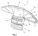
- the spouted pouch is provided with a three-component closure assembly 5, that is composed of:
- the spout has a spout body 11, e.g. injection moulded of plastic material.
- the spout 10 is molded of plastic, preferably as a unitary spout body, e.g. of polyethylene (PE) or of polypropylene (PP).
- PE polyethylene
- PP polypropylene
- the spout body has, in a lower end or region thereof, an attachment portion 12 that is attached to a flexible material pouch body.
- the depicted spout 10 is adapted to be secured with the portion 12 thereof between opposed film walls of a collapsible pouch 1.
- the portion 11 here is essentially boat-shaped or canoe in horizontal cross-section but other shapes, e.g. oval, elliptical, circular, diamond, etc., are also possible.
- attachment may involve heat sealing, wherein the material of the pouch is heat sealed to the portion 12.
- the spout body 11 further has a tubular neck 14 that extends upward from the attachment portion 12.
- the neck 14 delimits a section of a product passage 15 that extends through the spout body 12.
- the neck 14 has a lower end integral with the attachment portion 12, an upper end having an upper rim 16 about an upper opening 17 of the passage 15
- the neck 14 has an interior surface 18 and an exterior surface 19.
- the cap unit 30 comprises a cap body 35, an integrated ring member 50, and, as preferred, an integrated strap 65 permanently securing the cap body 35 to the ring member 50.
- the cap unit 30 is made, e.g. moulded, as one piece of plastic material distinct from the spout 10.
- the cap body 35 comprises a top wall structure 36 and a downward depending skirt 37, which has an interior side 37a, an exterior side 37b, and a lower edge 37c remote from the top wall structure 36.
- the ring member 50 is integrally formed to the lower edge 37c of the skirt 37 of the cap body.
- the ring member comprises an annular base portion 51 which is connected via breakable bridges 53 to the skirt 37 of the cap body 35. These breakable bridges 53 break upon first time removal of the cap body by a user for dispensing of product from the pouch 1.
- the annular base portion 51 and the spout body 11 have cooperating permanent snap-fit joint portions that keep the ring member 50 fixed to the spout 10 upon removal of the cap body 35 by the user.
- the spout body is an integrally formed circumferential wall portion 20 that extends coaxially about a section of the neck to form an inner space 22 that is open from above for receiving the annular base portion 51 of the ring member therein.
- the wall portion 20 has at least one snap-fit feature for cooperation with a snap-fit feature of the base portion to form a permanent snap-fit.
- the circumferential wall 20 is erected on a circumferential flange 11a of the spout body that extends around the neck 14.
- the spout body has an upper flange 11a and a lower flange 11b, e.g. allowing for handling of the spout as is known in the art.
- the wall portion 21 has multiple windows 21 therein, distributed about the circumference of the wall portion.
- the base portion has outwardly protruding snap portions 56 that each snap into a corresponding window 21.
- the wall portion has two sets of windows 21 for two sets of snap portions 56 at opposed sides of the neck, e.g. aligned in the plane of the top edge of the pouch.
- the wall portion 20 has, preferably in addition to the windows 21, one or more further windows 23, here two windows arranged diametrically opposite relative to the neck 14. These further windows 23 each cooperate with another snap portion 56.
- the further windows 23 each cooperate with a latch tab of the overcap 35 in order to provide a releasable snap connection between the overcap 35 and the spout.
- the ring member 50 When placing the cap unit 30 on the spout, e.g. as preferred with the flow control device 80 being pre-assembly with the cap unit as a subassembly, the ring member 50 enters the inner space 21 and snaps into place.
- the presence of the circumferential wall portion 20 provides a shield that shields the ring member 50 that has been introduced in the inner space 21.
- the ring member 50 is shielded by the wall 20 which reduces a risk of an undesired release of the ring member 50 once the cap body 35 has been removed.
- the wall 20 may make it more difficult to loosen the ring member 50 by an act from the outside, like for example releasing the ring member 50 by nibbling on the neck of an opened closure assembly.
- the flow control device 80 here is embodied to create a push-pull valve of the spouted pouch 1.
- the flow control device 80 is mounted to the neck 14 and has an external part, here embodied as a collar 81, that is located outside of the exterior surface of the neck 14.
- the flow control device 80 is configured to provide control of the flow of product from the pouch body through the product passage 15.
- the cap body 35 is arranged over the neck 14 and the flow control device 80.
- the ring member 50 and the external part 82 of the flow control device have cooperating retention portions 55, 83 that retain the flow control device 80 relative to the spout 10.
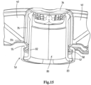
- the depicted flow control device 80 is a slidable valve member that is mounted on the neck 14 so as to be slidable upward relative to the neck 14 from a closed position to an opened position (see figure 15 ) to open the product passage 15 and downward to the closed position to close the product passage.
- the flow control device 80 is embodied to provide a closed position, so the functionality to keep the product passage closed.
- the cap body 35 is embodied as a protective overcap, so lacking the functionality to close the product passage 15.
- the protective overcap 35 primarily serves to shield the neck 14 and flow control device 80 from access prior to removal of the cap body 35.
- the flow control device 80 is molded of plastic material, e.g. as one piece, e.g. of PE or PP.
- cap body 35 prevents the slidable valve member 80 from being moved into the opened position, e.g. by internal pressure and/or by external tampering.
- the slidable valve member 80 has one or more sealing surfaces cooperating with one or more sealing surfaces of the neck of the spout in the closed position.
- the retention portions define the opened position of the slidable valve member and prevent further upward motion of the valve member 80.
- the external portion of the slidable valve member is embodied with a collar 82 that extends around the exterior of the neck and with one or more outward protrusions forming one or more retention portions, here a flange 83 at a lowermost edge of the collar 82.
- the ring member 50 is configured to allow for up and down sliding of the slidable valve member 82.
- the ring member 50 comprises a retention portion 55 forming an abutment for the outward protrusion, here flange 83, which abutment limits the upward motion of the slidable valve member relative to the neck and defines the opened position of the slidable valve member 82.
- the ring member and the slidable valve member have cooperating snap-fit portions that create a releasable snap-fit in at least one of the opened and the closed position of the slidable valve member, here in both the opened and closed position.
- the annular base portion 51 of the ring member defines two snap-fit recesses 57, 58 at different heights for a portion of the outer periphery of an outward protrusion, here flange 83, of the slidable valve member 82.
- the lower recess 57 receives the flange 83 therein in a releasable snap-fit when the valve member 82 is in the closed position, and the upper recess 58 receives therein the flange 83 in the opened position of the valve member, again in a releasable snap fit.
- a light snap is provided for between the overcap body 35 and the flow control device 80 in combination with a stronger snap between the flow control device 80 and the spout 10.
- the stronger snap provided by recess 58 cooperating with flange 83 will hold the slidable valve member 80 in its closed position as the user removes the overcap body 35 through release of a lighter snap between the overcap body and the member 80, e.g. as provided by one or more snap formations 39 (see figure 11 ) on the inside of the cap body 35 engaging underneath, or otherwise interacting with, a portion of the collar 82.
- the one or more sealing surfaces are located in proximity of the open upper end of the neck 14.
- An internal or first seal is formed between a sealing surface 18a on the inner surface 18 of the neck 14 and a sealing surface 86 of an inner annular wall portion 85 of the slidable valve member that extends into the neck 14.
- An external, or second seal is formed between a sealing surface 19a on the exterior surface of the neck and a sealing surface 82a of the collar 82 of the slidable valve member 80.
- the slidable valve member 80 has a transverse central wall portion 84 and adjoining along a periphery thereof an upwardly extending inner annular wall portion 85 forming a sealing surface 86 of the internal seal that cooperates with a sealing surface on the inner surface of the neck.
- the inner annular wall portion 85 connects via a bridge wall portion 87 to the top end of the collar 82 that extends coaxially about the inner annular wall portion 85.
- An open-bottomed groove 88 is present between the collar 82 and the coaxial inner annular wall portion 85. At least in the closed position, the upper end of the neck 14 is received in the groove 88.
- the valve member 80 is provided with outflow openings 89 which come into communication with the interior of the neck when the valve member is moved into the opened position so as to disengage the internal seal.
- the user For discharge of product from the pouch 1, the user first removes the cap body 35 in which process the bridges 53 break evidencing the first time opening of the closure assembly. Then the user has access to the slidable valve member 80, which is then slid upward by the user from the initial closed position into the opened position. This opened condition of the closure assembly is depicted in figure 15 .
- Figure 15 illustrates a subassembly of the cap unit 35 and the flow control member 80 prior to mounting on the spout 10.
- the flow control member 80 is snap-fitted with a releasable, e.g. light, snap-fit join in the cap unit.
- this releasable snap-fit is provided by the lower recess 57 which receives the flange 83 therein.
- the subassembly allows for an effective method for the production of filled spouted pouches 1.
- the method comprises:
- Figure 16 shows a variant of the subassembly, wherein the flow control device 80' is embodied as a slit valve 90.
- the cooperating retention portions 55' of the ring member 50' and of the flow control device retain the flow control device relative to the spout in one fixed position, so immobile relative to the spout. This is envisaged as the slit valve 90 requires no motion relative to the neck.
- Figure 17 shows another variant of the subassembly, wherein the flow control device 80" is embodied as a flow restrictor 95 having one or more outflow openings 95, here one, that have a smaller cross-section than the product passage delimited by the spout 10.
- the device 80" need not be mobile relative to the neck, at least not up and down. So, as shown, the ring member 50' keeps the device 80" in one fixed position.
- cap body 35 now has a closing functionality, as the closing portion 96 thereof sealingly cooperates with the flow control device 80 to hermetically close the pouch in the closed position of the cap body 35.
- closing portion 96 sealingly cooperates with the flow control device 80 to hermetically close the pouch in the closed position of the cap body 35.
- the figure 17 serves as a simple example.
- the cap unit 30 comprises a cap body 35 embodied as a protective overcap, an integrated ring member 50, and, as preferred, an integrated strap 65 permanently securing the cap body 35 to the ring member 50'.
- the cap body comprises one or more, here a pair of wing-shaped handles 40, here just one pair of wing-shaped handles, the one or more wing-shaped handles extending outwardly from the skirt 37, here in mutually opposite directions. These handles are configured to be engaged by a user for removal of the cap body.
- the strap 65 is integral at a first end 71 thereof to the base portion 51 of the member 50 and at a second end 72 thereof integral to one of the wing-shaped handles 40.
- the strap 65 is adapted to remain connected to both the base portion of the ring member and the respective wing-shaped handle upon removal of the overcap by the user.
- the strap 65 prior to first time removal of the overcap by the user, is located in a plane, e.g. in a vertical plane, that is in common with a panel portion of the respective wing-shaped handle 40.
- the strap 65 extends outward from the base portion 51 towards a tip of the respective wing-shaped handle along the bottom side of the wing-shaped handle, further about the tip of the wing-shaped handle, and then along a portion of the top side of the wing-shaped handle to the second end 72 of the strap.
- the second end is located inward of the tip of the handle 40, yet at a distance outward of the skirt 32.
- the handles 40 each have at least one reinforcing top protrusion 76 that is integral with at least a portion of the top side of the panel portion of the respective handle 40 and which top protrusion protrudes away from main face of the panel portion so as to reinforce the panel, e.g. in view of forces applied by the user upon rotating the cap body for removal thereof.
- the strap 65 is integral at a first end thereof to the base portion of the ring member and extends from the first end 71 along the bottom side of the panel portion about the tip of the panel portion to a second end 72 of the strap, wherein the second end of the strap adjoins the outer end of the reinforcing top protrusion 76.
- the cap unit comprises one or more breakable tamper-evident bridges 74 that are located between the strap 65 and the respective wing-shaped handle 40, said one or more breakable tamper-evident bridges 74 breaking upon first time removal of the overcap by a user.
- an integrally molded breakable film portion 74 extends over a major part of the length of the strap 65 between the handle 40 and the strap 40. Upon removal of the overcap 35 this film portion 74 is torn.
- the cap unit is embodied with a quarter turn lift overcap 35. So, in general, the user will turn the overcap over about a quarter turn in the process of removal of the overcap.
- the ring member 50 is provided with at least one, here two diametrically opposed, first cam portion 61 which defines a cam surface 62, which cam surface 62 is angled with respect to a main axis of the neck 14.
- the first cam portion 61 is integrally formed on the annular base portion 51 of the ring member 50.
- skirt of the overcap 35 is provided with at least one, here two diametrically opposed, second cam portion 63 defining a cam follower surface 64 adapted to interact with the cam surface 62 of the first cam portion 61.
- the second cam portions 63 each are part of a downwardly extending tab 38 integrally formed at the lower end of the skirt and adapted to cooperate with the first cam surface 62.
- the cap body has two tabs 38 extending downwardly at diametrically opposed positions.
- the first and second cam portions 61, 63 interact in order to cause axial lifting of the overcap relative to the neck 14, e.g. enhancing that the bridges 53 break and any cooperating snap connector formations between the overcap 35 and the spout disengage.
- each first cam portion 61 has an upwardly arched first cam surface 62 with a centre and with first and second ends where the arched first cam surface adjoins the top face 54a of the flange-like portion 51.
- a breakable bridge 53 is present at each end of the upwardly arched first cam surface 62.
- a top region of the annular base portion 51 protrudes upwardly above the circumferential wall 20 and that the strap 65 adjoins at the first end thereof 71 this upwardly protruding top region.
- the top region is part of the cam portion 61 on the ring member 50.
- the tabs 38 could have the dual function of providing the second cam portion 63 as well as being embodied as a latch tab to provide a releasable snap connection between the overcap 35 and the spout, which snap connection is also of use after the first time opening allowing the user to close the pouch again.
- the user When placing the overcap 35 back onto the spout, e.g. latching the overcap 35 as described herein, the user automatically pushes the slidable valve member 82 down into the closed position thereof, as is preferred.
Landscapes
- Engineering & Computer Science (AREA)
- Mechanical Engineering (AREA)
- Closures For Containers (AREA)
- Making Paper Articles (AREA)
- Bag Frames (AREA)
Claims (12)
- Mit einem Ausguss versehener Beutel (1), umfassend:- einen aus einem flexiblen Material bestehenden Beutelkörper (2), der mit einem abzugebenden Produkt befüllt ist,- einen Ausguss (10), der einen Ausgusskörper (11) mit einem Anbringungsteil (12) aufweist, der an einem aus einem flexiblen Material bestehenden Beutelkörper angebracht ist, wobei der Ausgusskörper einen röhrenförmigen Hals (14) aufweist, der sich von dem Anbringungsteil nach oben erstreckt, wobei der Hals einen Abschnitt eines Produktdurchgangs (15), der sich durch den Ausgusskörper erstreckt, begrenzt, wobei der Hals eine Außenfläche (19) aufweist,- eine Kappeneinheit (30), die einen Kappenkörper (35) und ein integriertes Ringelement (50) umfasst, wobei die Kappeneinheit in einem Stück aus einem Kunststoffmaterial, das sich von dem Ausguss (10) unterscheidet, hergestellt, zum Beispiel geformt, worden ist,wobei der Kappenkörper (35) eine obere Wandstruktur (36) und eine nach unten abgehende Schürze (37) umfasst, die eine Innenseite (37a), eine Außenseite (37b) und einen unteren Rand (37c) der sich von der oberen Wandstruktur (36) entfernt befindet, aufweist,wobei das Ringelement (50) einstückig mit dem unteren Rand der Schürze des Kappenkörpers ausgebildet ist, wobei das Ringelement einen ringförmigen Basisteil (51) umfasst, der wenigstens über eine oder mehrere zerbrechliche Brücken (53) mit der Schürze des Kappenkörpers verbunden ist, wobei die eine oder die mehreren zerbrechlichen Brücken zerbrechen, wenn ein Benutzer zum ersten Mal den Kappenkörper entfernt, um ein Produkt über den Produktdurchgang aus dem Beutel abzugeben,wobei der ringförmige Basisteil (51) und der Ausgusskörper (11) zusammenwirkende dauerhafte Steckverbindungsteile (56, 21, 23) aufweisen, die das Ringelement (50) beim Entfernen des Kappenkörpers (35) durch den Benutzer an dem Ausguss befestigt halten,dadurch gekennzeichnet, dass der mit einem Ausguss versehene Beutel ferner Folgendes umfasst:- eine Durchflussregelungsvorrichtung (80), die getrennt von dem Ausguss (10) und von der Kappeneinheit (30) hergestellt worden ist, wobei die Durchflussregelungsvorrichtung an dem Hals (14) befestigt ist und einen Außenteil (82) aufweist, der sich außerhalb der Außenfläche des Halses befindet, wobei die Durchflussregelungsvorrichtung dazu ausgelegt ist, die Regelung des Produktdurchflusses aus dem Beutelkörper durch den Produktdurchgang (15) bereitzustellen,wobei der Kappenkörper (35) über dem Hals (14) und der Durchflussregelungsvorrichtung (80) angeordnet ist undwobei das Ringelement (50) und der Außenteil (82) der Durchflussregelungsvorrichtung (80) zusammenwirkende Halteteile (55, 83) aufweisen, die die Durchflussregelungsvorrichtung (80) relativ zu dem Ausguss (10) halten.
- Mit einem Ausguss versehener Beutel nach Anspruch 1, wobei es sich bei der Durchflussregelungsvorrichtung um ein verschiebbares Ventilelement (80) handelt, das so an dem Hals befestigt ist, dass es ein Push-Pull-Ventil bildet und dass es relativ zu dem Hals (14) aus einer geschlossenen Stellung in eine geöffnete Stellung nach oben verschiebbar ist, um den Produktdurchgang (15) zu öffnen, und nach unten in die geschlossene Stellung verschiebbar ist, um den Produktdurchgang zu schließen, wobei das verschiebbare Ventilelement eine oder mehrere Dichtungsflächen (82a, 86) aufweist, die in der geschlossenen Stellung mit einer oder mehreren Dichtungsflächen (19a, 18a) des Halses (14) des Ausgusses zusammenwirken, und wobei die Halteteile (55, 83) die nach oben gerichtete Bewegung des verschiebbaren Ventilelements begrenzen, z.B. die geöffnete Stellung des verschiebbaren Ventilelements definieren.
- Mit einem Ausguss versehener Beutel nach Anspruch 2, wobei der Außenteil des verschiebbaren Ventilelements mit einem Bund (82) ausgestaltet ist, der sich um die Außenseite des Halses erstreckt, und wobei ein oder mehrere nach außen gerichtete Vorsprünge einen oder mehrere Halteteile, z.B. einen Flansch (83), an einem untersten Rand des Bundes (82) bilden, und wobei das Ringelement (51) dazu ausgelegt ist, zu ermöglichen, dass das verschiebbare Ventilelement (80) nach oben und unten verschiebbar ist, wobei das Ringelement einen Halteteil (55) umfasst, der ein Auflager bildet, das die nach oben gerichtete Bewegung des verschiebbaren Ventilelements begrenzt, z.B. die geöffnete Stellung des verschiebbaren Ventilelements definiert.
- Mit einem Ausguss versehener Beutel nach Anspruch 2 oder 3, wobei sich die eine oder die mehreren Dichtungsflächen in der Nähe des oberen Endes des Halses (14) befinden, wobei vorzugsweise eine Innendichtung zwischen einer Dichtungsfläche (18a) auf der Innenfläche des Halses (14) und einer Dichtungsfläche (86) eines inneren zur ringförmigen Wand gehörenden Teils (85) des verschiebbaren Ventilelements, der sich in den Hals erstreckt, und vorzugsweise eine Außendichtung zwischen einer Dichtungsfläche (19a) auf der Außenfläche des Halses und einer Dichtungsfläche (82a) des Bundes (82) des verschiebbaren Ventilelements gebildet sind.
- Mit einem Ausguss versehener Beutel nach einem oder mehreren der Ansprüche 2 bis 4, wobei das verschiebbare Ventilelement (80) einen quer verlaufenden zur mittleren Wand gehörenden Teil (84) und angrenzend entlang einem Umfang davon einen nach oben sich erstreckenden inneren zur ringförmigen Wand gehörenden Teil (85) aufweist, der eine Dichtungsfläche (86) einer Innendichtung bildet, die mit einer Dichtungsfläche (18a) auf der Innenfläche des Halses zusammenwirkt, wobei sich der innere zur ringförmigen Wand gehörende Teil (85) über einen Brückenwandteil (87) an die Oberseite des Bundes (82) anschließt, der sich koaxial um den inneren zur ringförmigen Wand gehörenden Teil (85) erstreckt, wobei zwischen dem Bund (82) und dem inneren zur ringförmigen Wand gehörenden Teil eine mit einem Boden versehene Rille (88) vorhanden ist, in der das obere Ende des Halses (14) aufgenommen ist.
- Mit einem Ausguss versehener Beutel nach einem oder mehreren der Ansprüche 1 bis 5, wobei die Durchflussregelungsvorrichtung so ausgestaltet ist, dass sie den Produktdurchgang geschlossen hält, wenn der Kappenkörper durch den Benutzer entfernt wird, z.B. als Ventil, zum Beispiel als verschiebbares Ventilelement (80), um ein Push-Pull-Ventil zu schaffen, und wobei der Kappenkörper (35) als Schutzkappe ausgestaltet ist.
- Mit einem Ausguss versehener Beutel nach einem oder mehreren der Ansprüche 1 bis 6, wobei es sich bei dem Kappenkörper um einen aufsteckbaren Kappenkörper (35) handelt, der eine Steckfunktionalität bereitstellt, so dass der Kappenkörper ersetzt werden kann, nachdem er zum ersten Mal entfernt worden ist, wobei der Ausguss und/oder die Durchflussregelungsvorrichtung (80) einerseits und der Kappenkörper (35) andererseits mit zusammenwirkenden Steckverbindungsausbildungen (39) versehen sind, um die Steckfunktionalität bereitzustellen.
- Mit einem Ausguss versehener Beutel nach einem oder mehreren der Ansprüche 1 bis 7, wobei der Kappenkörper einen oder mehrere, z.B. ein Paar, flügelförmige Griffe (40), z.B. nur ein Paar von flügelförmigen Griffen, umfasst, wobei sich der eine oder die mehreren flügelförmigen Griffe von der Schürze (37) nach außen, z.B. in gegenseitig entgegengesetzten Richtungen, erstrecken und dazu ausgelegt sind, zum Entfernen des Kappenkörpers durch einen Benutzer in Eingriff gebracht zu werden.
- Mit einem Ausguss versehener Beutel nach einem oder mehreren der Ansprüche 1 bis 8, wobei die Kappeneinheit ferner ein integriertes Halteband (65) umfasst, das den Kappenkörper (35) sicher und dauerhaft an dem Ringelement (50) befestigt, wobei z.B. bei einer Ausgestaltung nach Anspruch 8 das Halteband (65) sich an einen flügelförmigen Griff des Kappenkörpers anschließt, wobei sich z.B. das Halteband (65), bevor der Kappenkörper durch den Benutzer zum ersten Mal entfernt wird, in einer Ebene, z.B. einer vertikalen Ebene, befindet, die die gleiche wie die eines Plattenteils des entsprechenden flügelförmigen Griffs (40) ist.
- Mit einem Ausguss versehener Beutel nach einem oder mehreren der Ansprüche 1 bis 9, wobei die Kappeneinheit mit einer Dreh-Hub-Funktionalität, z.B. einer Hub-Funktionalität mit einer Vierteildrehung, ausgestaltet ist und Folgendes umfasst:- wenigstens einen ersten Nockenteil (61), der eine Nockenfläche (62) definiert, wobei die Nockenfläche (62) in Bezug auf eine Hauptachse (A) des Halses (14) abgewinkelt ist, wobei der erste Nockenteil (61) auf dem einen von dem unteren Rand (37c) der Schürze und dem Ringelement (50) einstückig ausgebildet ist, und- wenigstens einen zweiten Nockenteil (63), der eine Nockenmitnehmerfläche (64) definiert, die geeignet ist, mit der Nockenfläche (62) des ersten Nockenteils (61) zu interagieren, und wobei der zweite Nockenteil auf dem anderen von dem unteren Rand der Schürze (32) und dem Ringelement (50) einstückig ausgebildet ist,wobei, wenn der Kappenkörper (35) zum ersten Mal durch eine Drehung um die Hauptachse (A) relativ zu dem Hals (14) geöffnet wird, der erste und der zweite Nockenteil interagieren, um ein axiales Anheben des Kappenkörpers relativ zu dem Hals (11) zu bewirken, so dass z.B. die zusammenwirkenden Steckverbindungsausbildungen (39) außer Eingriff gelangen.
- Verschlussanordnung für einen mit einem Ausguss versehenen Beutel, wobei die Verschlussanordnung Folgendes umfasst:- einen Ausguss (10), der einen Ausgusskörper mit einem an einem unteren Ende davon befindlichen Anbringungsteil (11) aufweist, der dazu ausgelegt ist, an einem aus einem flexiblen Material bestehenden Beutelkörper angebracht zu sein, wobei der Ausgusskörper an einem oberen Ende davon einen röhrenförmigen Hals (14) aufweist, wobei der Hals einen Abschnitt eines Produktdurchgangs (15), der sich durch den Ausgusskörper erstreckt, begrenzt, wobei der Hals eine Außenfläche aufweist,- eine Kappeneinheit (30), die einen Kappenkörper (35), ein integriertes Ringelement (50) und optional ein integriertes Halteband (65), das den Kappenkörper sicher und dauerhaft an dem Ringelement befestigt, umfasst, wobei die Kappeneinheit in einem Stück aus einem Kunststoffmaterial, das sich von dem Ausguss unterscheidet, hergestellt, zum Beispiel geformt, ist,wobei der Kappenkörper (35) eine obere Wandstruktur (36) und eine nach unten abgehende Schürze (37) umfasst, die eine Innenseite (37a), eine Außenseite (37b) und einen unteren Rand (37c) aufweist, der sich von der oberen Wandstruktur (36) entfernt befindet,wobei das Ringelement (50) einstückig mit dem unteren Rand der Schürze des Kappenkörpers ausgebildet ist, wobei das Ringelement einen ringförmigen Basisteil (51) umfasst, der wenigstens über eine oder mehrere zerbrechliche Brücken (53) mit der Schürze des Kappenkörpers verbunden ist, wobei die eine oder die mehreren zerbrechlichen Brücken zerbrechen, wenn ein Benutzer zum ersten Mal den Kappenkörper entfernt, um ein Produkt aus dem Beutel abzugeben,wobei der ringförmige Basisteil (51) und der Ausgusskörper zusammenwirkende dauerhafte Steckverbindungsteile (21, 23, 56) aufweisen, die dazu ausgelegt sind, das Ringelement beim Entfernen des Kappenkörpers (35) durch den Benutzer an dem Ausguss befestigt zu halten,dadurch gekennzeichnet, dass die Anordnung ferner Folgendes umfasst:- eine Durchflussregelungsvorrichtung (80), die getrennt von dem Ausguss (10) und von der Kappeneinheit (30) hergestellt ist, wobei die Durchflussregelungsvorrichtung dazu ausgelegt ist, an dem Hals befestigt zu sein, und einen Außenteil (82) aufweist, der sich außerhalb der Außenfläche des Halses befindet, wenn die Durchflussregelungsvorrichtung an dem Hals befestigt worden ist, wobei die Durchflussregelungsvorrichtung dazu ausgelegt ist, die Regelung des Produktdurchflusses aus dem Beutelkörper durch den Produktdurchgang bereitzustellen,wobei der Kappenkörper (35) dazu ausgelegt ist, über dem Hals (14) und der Durchflussregelungsvorrichtung (80) angeordnet zu sein, wenn er an dem Hals befestigt ist, undwobei das Ringelement (50) und der Außenteil (82) der Durchflussregelungsvorrichtung zusammenwirkende Halteteile (55, 83) aufweisen, die dazu ausgelegt sind, die Durchflussregelungsvorrichtung relativ zu dem Ausguss zu halten.
- Verfahren zum Herstellen von befüllten mit einem Ausguss versehenen Beuteln nach einem oder mehreren der vorhergehenden Ansprüche, wobei das Verfahren Folgendes umfasst:- Versehen eines leeren Beutels (1) mit einem Ausguss (10) nach einem oder mehreren der vorhergehenden Ansprüche, der an dem Beutelkörper (2) befestigt ist,- Befüllen des Beutels mit einem Produkt über den Produktdurchgang (15),- Bereitstellen einer Teilanordnung aus der Kappeneinheit (30) und dem Durchflussregelungselement (80) nach einem oder mehreren der vorhergehenden Ansprüche, z.B. des verschiebbaren Ventilelements (82), wobei das Durchflussregelungselement zunächst innerhalb des Kappenkörpers gehalten (57, 83) ist,- Befestigen der Teilanordnung an dem Ausguss (10) nach dem Befüllen des Beutels, wobei das Befestigen das Pressen der Teilanordnung auf den Ausguss umfasst, so dass die Durchflussregelungsvorrichtung (80) an dem Hals befestigt wird und so dass die zusammenwirkenden dauerhaften Steckverbindungsteile (56, 21, 23) des ringförmigen Basisteils und der Ausgusskörper in Eingriff gelangen und das Ringelement (50) an dem Ausguss befestigt halten.
Applications Claiming Priority (2)
| Application Number | Priority Date | Filing Date | Title |
|---|---|---|---|
| NL2026679A NL2026679B1 (nl) | 2020-10-15 | 2020-10-15 | Spouted pouch and a closure assembly |
| PCT/EP2021/078418 WO2022079154A1 (en) | 2020-10-15 | 2021-10-14 | Spouted pouch and a closure assembly |
Publications (3)
| Publication Number | Publication Date |
|---|---|
| EP4228977A1 EP4228977A1 (de) | 2023-08-23 |
| EP4228977C0 EP4228977C0 (de) | 2024-07-31 |
| EP4228977B1 true EP4228977B1 (de) | 2024-07-31 |
Family
ID=74125614
Family Applications (1)
| Application Number | Title | Priority Date | Filing Date |
|---|---|---|---|
| EP21793906.5A Active EP4228977B1 (de) | 2020-10-15 | 2021-10-14 | Beutel mit ausguss, verschlussanordnung und herstellungsverfahren |
Country Status (6)
| Country | Link |
|---|---|
| US (1) | US11884459B2 (de) |
| EP (1) | EP4228977B1 (de) |
| CN (1) | CN116368074B (de) |
| AU (1) | AU2021359074A1 (de) |
| NL (1) | NL2026679B1 (de) |
| WO (1) | WO2022079154A1 (de) |
Families Citing this family (4)
| Publication number | Priority date | Publication date | Assignee | Title |
|---|---|---|---|---|
| NL2026679B1 (nl) * | 2020-10-15 | 2022-06-14 | Scholle Ipn Ip Bv | Spouted pouch and a closure assembly |
| NL2032005B1 (en) * | 2022-05-27 | 2023-12-11 | Scholle Ipn Ip Bv | Closure assembly with a cap having corrugated wings |
| NL2032534B1 (en) * | 2022-07-18 | 2024-01-26 | Scholle Ipn Ip Bv | A spouted container and closure assembly. |
| IT202300014775A1 (it) * | 2023-07-14 | 2025-01-14 | Acqua Minerale San Benedetto S P A | Tappo erogatore per bottiglie |
Family Cites Families (29)
| Publication number | Priority date | Publication date | Assignee | Title |
|---|---|---|---|---|
| US3731847A (en) * | 1971-06-01 | 1973-05-08 | Gillette Co | Plural compartment pressurized dispensing package |
| US4728006A (en) * | 1984-04-27 | 1988-03-01 | The Procter & Gamble Company | Flexible container including self-sealing dispensing valve to provide automatic shut-off and leak resistant inverted storage |
| BR8807106A (pt) * | 1987-06-26 | 1989-10-31 | Werding Winfried J | Dispositivo para armazenagens e fornecimento controlado de produtos que se encontram sob pressao |
| US5033647A (en) * | 1990-03-09 | 1991-07-23 | Allergan, Inc. | Value controlled squeezable fluid dispenser |
| WO2000037327A1 (en) * | 1998-12-22 | 2000-06-29 | Tadashi Hagihara | Self-standing bag container equipped with vacuum and flow rate control functions |
| US7249694B2 (en) * | 2002-07-26 | 2007-07-31 | Masatoshi Masuda | Valve mechanism for tube-type fluid container |
| NL2005329C2 (en) * | 2010-09-08 | 2012-03-12 | Ipn Ip Bv | A closure device. |
| NL2008558C2 (en) * | 2012-03-29 | 2013-10-01 | Ipn Ip Bv | Container closure assemblies. |
| NL2009109C2 (en) | 2012-07-03 | 2014-01-06 | Ipn Ip Bv | A closure assembly. |
| BR112016002967A2 (pt) * | 2013-08-14 | 2017-08-01 | Ipn Ip Bv | recipiente para transporte e armazenamento de um líquido |
| ES2820701T3 (es) * | 2013-11-26 | 2021-04-22 | Nestle Sa | Adaptadores para envases de productos consumibles y procedimiento para la utilización de los mismos |
| NL2012170C2 (en) | 2014-01-30 | 2015-08-06 | Ipn Ip Bv | Assembly machine adapted to assemble caps onto spouts and a method of assembling caps onto spouts. |
| NL2012469B1 (en) * | 2014-03-18 | 2015-12-15 | Ipn Ip Bv | A liquid dispensing tap and liquid container provided with said tap. |
| WO2017035037A1 (en) * | 2015-08-21 | 2017-03-02 | Acorn Bay | Valve system |
| US9737913B2 (en) * | 2015-09-21 | 2017-08-22 | Scholle Ipn Corporation | Pouch cleaning assembly for an aseptic filler |
| NL2015473B1 (en) * | 2015-09-21 | 2017-04-19 | Scholle Ipn Ip Bv | A spouted pouch adapted to be filled with a flowable product. |
| US10035614B2 (en) * | 2015-09-21 | 2018-07-31 | Scholle Ipn Corporation | Method for aseptic filling of pouches |
| US9751677B2 (en) * | 2015-09-21 | 2017-09-05 | Scholle Ipn Corporation | Pouch assembly having a plug |
| NL2016005B1 (en) * | 2015-12-22 | 2017-07-03 | Scholle Ipn Ip Bv | Needleless syringe connector cap. |
| NL2016212B1 (en) | 2016-02-03 | 2017-08-11 | Scholle Ipn Ip Bv | A closure assembly and container provided with said closure assembly. |
| US10654628B2 (en) * | 2017-11-01 | 2020-05-19 | Scholle Ipn Ip Bv | Cap for a pouch |
| US11053054B2 (en) * | 2018-08-03 | 2021-07-06 | Gateway Plastics, Inc. | Spout fitment and cap |
| EP4234434A3 (de) * | 2018-09-07 | 2023-11-01 | Scholle IPN IP B.V. | Verschlussanordnung mit einer kappe mit integriertem originalitätsringelement |
| NL2022097B1 (en) * | 2018-11-29 | 2020-06-26 | Scholle Ipn Ip Bv | A spouted pouch provided with a closure device |
| ES2958482T3 (es) * | 2019-04-30 | 2024-02-09 | Scholle Ipn Ip Bv | Un conjunto de cierre que comprende una tapa con un elemento de anillo a prueba de manipulación y una banda integrados |
| CN211283693U (zh) * | 2019-12-18 | 2020-08-18 | 康美包(苏州)有限公司 | 一种节流系统以及灌装机 |
| US12157617B2 (en) * | 2020-02-14 | 2024-12-03 | Sig Services Ag | Plastic spout and pouch packaging |
| NL2026679B1 (nl) * | 2020-10-15 | 2022-06-14 | Scholle Ipn Ip Bv | Spouted pouch and a closure assembly |
| AU2023219700A1 (en) * | 2022-02-11 | 2024-07-18 | Silgan White Cap LLC | Tethered, hinged closure with modified primary slit |
-
2020
- 2020-10-15 NL NL2026679A patent/NL2026679B1/nl active
-
2021
- 2021-10-14 EP EP21793906.5A patent/EP4228977B1/de active Active
- 2021-10-14 WO PCT/EP2021/078418 patent/WO2022079154A1/en not_active Ceased
- 2021-10-14 AU AU2021359074A patent/AU2021359074A1/en active Pending
- 2021-10-14 US US18/032,166 patent/US11884459B2/en active Active
- 2021-10-14 CN CN202180070176.2A patent/CN116368074B/zh active Active
Also Published As
| Publication number | Publication date |
|---|---|
| US11884459B2 (en) | 2024-01-30 |
| CN116368074B (zh) | 2025-08-05 |
| EP4228977C0 (de) | 2024-07-31 |
| CN116368074A (zh) | 2023-06-30 |
| AU2021359074A1 (en) | 2023-05-04 |
| EP4228977A1 (de) | 2023-08-23 |
| US20230348155A1 (en) | 2023-11-02 |
| NL2026679B1 (nl) | 2022-06-14 |
| WO2022079154A1 (en) | 2022-04-21 |
Similar Documents
| Publication | Publication Date | Title |
|---|---|---|
| EP4228977B1 (de) | Beutel mit ausguss, verschlussanordnung und herstellungsverfahren | |
| EP2254804B1 (de) | Verschluss mit tropfenminimierungsdeckel | |
| RU2290356C2 (ru) | Открываемое посредством вращения дозирующее укупорочное средство, содержащее вспомогательное средство для прокалывания прокладки | |
| EP4242131B1 (de) | Verschlussanordnung mit einer kappe mit integriertem manipulationssicherem ring und band | |
| US6062441A (en) | Two-piece dispensing closure | |
| CN101102960B (zh) | 带有一个或多个盖子的罩盖 | |
| US4600130A (en) | Squeeze pressure dispenser with integral siphon tube | |
| EP3887278B1 (de) | Tüllenbeutel mit verschlussvorrichtung | |
| AU2002320484A1 (en) | Twist Openable Dispensing Closure Accommodating Optional Liner Puncture Feature | |
| WO2010036645A1 (en) | Baffled dispensing closure | |
| NZ199345A (en) | A rupturable lid and container assembly:snap lock fit | |
| US8893912B2 (en) | Closure device | |
| HUP0303572A2 (hu) | Flexibilis műanyag záróelem, főként palackokhoz | |
| PL202171B1 (pl) | Zespół dozujący, posiadający przykrywkę z zamontowanym wepchniętym ciśnieniowo-otwieralnym zaworem | |
| WO1994029184A1 (en) | Clog-resistant toggle disk closure | |
| US20040169045A1 (en) | Application and assembly suited for use as a disposable leak proof child drinking cup | |
| WO2011146438A1 (en) | Container cap | |
| US20240375837A1 (en) | Container closure | |
| NL2032534B1 (en) | A spouted container and closure assembly. | |
| JP7455728B2 (ja) | ヒンジキャップ | |
| JPH0331710Y2 (de) | ||
| NL2023034B1 (en) | A closure assembly comprising a cap with integrated tamper-evident ring and strap | |
| RU2780685C1 (ru) | Укупорочный узел, содержащий колпачок с кольцевым элементом для индикации вскрытия, образующим одно целое с ним | |
| EP1619133B1 (de) | Behälterverschluss |
Legal Events
| Date | Code | Title | Description |
|---|---|---|---|
| STAA | Information on the status of an ep patent application or granted ep patent |
Free format text: STATUS: UNKNOWN |
|
| STAA | Information on the status of an ep patent application or granted ep patent |
Free format text: STATUS: THE INTERNATIONAL PUBLICATION HAS BEEN MADE |
|
| PUAI | Public reference made under article 153(3) epc to a published international application that has entered the european phase |
Free format text: ORIGINAL CODE: 0009012 |
|
| STAA | Information on the status of an ep patent application or granted ep patent |
Free format text: STATUS: REQUEST FOR EXAMINATION WAS MADE |
|
| 17P | Request for examination filed |
Effective date: 20230502 |
|
| AK | Designated contracting states |
Kind code of ref document: A1 Designated state(s): AL AT BE BG CH CY CZ DE DK EE ES FI FR GB GR HR HU IE IS IT LI LT LU LV MC MK MT NL NO PL PT RO RS SE SI SK SM TR |
|
| DAV | Request for validation of the european patent (deleted) | ||
| DAX | Request for extension of the european patent (deleted) | ||
| GRAP | Despatch of communication of intention to grant a patent |
Free format text: ORIGINAL CODE: EPIDOSNIGR1 |
|
| STAA | Information on the status of an ep patent application or granted ep patent |
Free format text: STATUS: GRANT OF PATENT IS INTENDED |
|
| INTG | Intention to grant announced |
Effective date: 20240221 |
|
| RAP1 | Party data changed (applicant data changed or rights of an application transferred) |
Owner name: SIG SERVICES AG |
|
| GRAS | Grant fee paid |
Free format text: ORIGINAL CODE: EPIDOSNIGR3 |
|
| GRAA | (expected) grant |
Free format text: ORIGINAL CODE: 0009210 |
|
| STAA | Information on the status of an ep patent application or granted ep patent |
Free format text: STATUS: THE PATENT HAS BEEN GRANTED |
|
| AK | Designated contracting states |
Kind code of ref document: B1 Designated state(s): AL AT BE BG CH CY CZ DE DK EE ES FI FR GB GR HR HU IE IS IT LI LT LU LV MC MK MT NL NO PL PT RO RS SE SI SK SM TR |
|
| REG | Reference to a national code |
Ref country code: CH Ref legal event code: EP Ref country code: GB Ref legal event code: FG4D |
|
| REG | Reference to a national code |
Ref country code: DE Ref legal event code: R096 Ref document number: 602021016561 Country of ref document: DE |
|
| REG | Reference to a national code |
Ref country code: IE Ref legal event code: FG4D |
|
| U01 | Request for unitary effect filed |
Effective date: 20240731 |
|
| U07 | Unitary effect registered |
Designated state(s): AT BE BG DE DK EE FI FR IT LT LU LV MT NL PT SE SI Effective date: 20240809 |
|
| U20 | Renewal fee for the european patent with unitary effect paid |
Year of fee payment: 4 Effective date: 20241030 |
|
| PG25 | Lapsed in a contracting state [announced via postgrant information from national office to epo] |
Ref country code: NO Free format text: LAPSE BECAUSE OF FAILURE TO SUBMIT A TRANSLATION OF THE DESCRIPTION OR TO PAY THE FEE WITHIN THE PRESCRIBED TIME-LIMIT Effective date: 20241031 |
|
| PG25 | Lapsed in a contracting state [announced via postgrant information from national office to epo] |
Ref country code: GR Free format text: LAPSE BECAUSE OF FAILURE TO SUBMIT A TRANSLATION OF THE DESCRIPTION OR TO PAY THE FEE WITHIN THE PRESCRIBED TIME-LIMIT Effective date: 20241101 Ref country code: PL Free format text: LAPSE BECAUSE OF FAILURE TO SUBMIT A TRANSLATION OF THE DESCRIPTION OR TO PAY THE FEE WITHIN THE PRESCRIBED TIME-LIMIT Effective date: 20240731 |
|
| PG25 | Lapsed in a contracting state [announced via postgrant information from national office to epo] |
Ref country code: IS Free format text: LAPSE BECAUSE OF FAILURE TO SUBMIT A TRANSLATION OF THE DESCRIPTION OR TO PAY THE FEE WITHIN THE PRESCRIBED TIME-LIMIT Effective date: 20241130 |
|
| PG25 | Lapsed in a contracting state [announced via postgrant information from national office to epo] |
Ref country code: HR Free format text: LAPSE BECAUSE OF FAILURE TO SUBMIT A TRANSLATION OF THE DESCRIPTION OR TO PAY THE FEE WITHIN THE PRESCRIBED TIME-LIMIT Effective date: 20240731 |
|
| PG25 | Lapsed in a contracting state [announced via postgrant information from national office to epo] |
Ref country code: ES Free format text: LAPSE BECAUSE OF FAILURE TO SUBMIT A TRANSLATION OF THE DESCRIPTION OR TO PAY THE FEE WITHIN THE PRESCRIBED TIME-LIMIT Effective date: 20240731 Ref country code: RS Free format text: LAPSE BECAUSE OF FAILURE TO SUBMIT A TRANSLATION OF THE DESCRIPTION OR TO PAY THE FEE WITHIN THE PRESCRIBED TIME-LIMIT Effective date: 20241031 |
|
| PG25 | Lapsed in a contracting state [announced via postgrant information from national office to epo] |
Ref country code: RS Free format text: LAPSE BECAUSE OF FAILURE TO SUBMIT A TRANSLATION OF THE DESCRIPTION OR TO PAY THE FEE WITHIN THE PRESCRIBED TIME-LIMIT Effective date: 20241031 Ref country code: PL Free format text: LAPSE BECAUSE OF FAILURE TO SUBMIT A TRANSLATION OF THE DESCRIPTION OR TO PAY THE FEE WITHIN THE PRESCRIBED TIME-LIMIT Effective date: 20240731 Ref country code: NO Free format text: LAPSE BECAUSE OF FAILURE TO SUBMIT A TRANSLATION OF THE DESCRIPTION OR TO PAY THE FEE WITHIN THE PRESCRIBED TIME-LIMIT Effective date: 20241031 Ref country code: IS Free format text: LAPSE BECAUSE OF FAILURE TO SUBMIT A TRANSLATION OF THE DESCRIPTION OR TO PAY THE FEE WITHIN THE PRESCRIBED TIME-LIMIT Effective date: 20241130 Ref country code: HR Free format text: LAPSE BECAUSE OF FAILURE TO SUBMIT A TRANSLATION OF THE DESCRIPTION OR TO PAY THE FEE WITHIN THE PRESCRIBED TIME-LIMIT Effective date: 20240731 Ref country code: GR Free format text: LAPSE BECAUSE OF FAILURE TO SUBMIT A TRANSLATION OF THE DESCRIPTION OR TO PAY THE FEE WITHIN THE PRESCRIBED TIME-LIMIT Effective date: 20241101 Ref country code: ES Free format text: LAPSE BECAUSE OF FAILURE TO SUBMIT A TRANSLATION OF THE DESCRIPTION OR TO PAY THE FEE WITHIN THE PRESCRIBED TIME-LIMIT Effective date: 20240731 |
|
| PG25 | Lapsed in a contracting state [announced via postgrant information from national office to epo] |
Ref country code: SM Free format text: LAPSE BECAUSE OF FAILURE TO SUBMIT A TRANSLATION OF THE DESCRIPTION OR TO PAY THE FEE WITHIN THE PRESCRIBED TIME-LIMIT Effective date: 20240731 |
|
| PG25 | Lapsed in a contracting state [announced via postgrant information from national office to epo] |
Ref country code: CZ Free format text: LAPSE BECAUSE OF FAILURE TO SUBMIT A TRANSLATION OF THE DESCRIPTION OR TO PAY THE FEE WITHIN THE PRESCRIBED TIME-LIMIT Effective date: 20240731 |
|
| PG25 | Lapsed in a contracting state [announced via postgrant information from national office to epo] |
Ref country code: SK Free format text: LAPSE BECAUSE OF FAILURE TO SUBMIT A TRANSLATION OF THE DESCRIPTION OR TO PAY THE FEE WITHIN THE PRESCRIBED TIME-LIMIT Effective date: 20240731 |
|
| REG | Reference to a national code |
Ref country code: CH Ref legal event code: PL |
|
| PLBE | No opposition filed within time limit |
Free format text: ORIGINAL CODE: 0009261 |
|
| STAA | Information on the status of an ep patent application or granted ep patent |
Free format text: STATUS: NO OPPOSITION FILED WITHIN TIME LIMIT |
|
| PG25 | Lapsed in a contracting state [announced via postgrant information from national office to epo] |
Ref country code: MC Free format text: LAPSE BECAUSE OF FAILURE TO SUBMIT A TRANSLATION OF THE DESCRIPTION OR TO PAY THE FEE WITHIN THE PRESCRIBED TIME-LIMIT Effective date: 20240731 |
|
| 26N | No opposition filed |
Effective date: 20250501 |
|
| PG25 | Lapsed in a contracting state [announced via postgrant information from national office to epo] |
Ref country code: CH Free format text: LAPSE BECAUSE OF NON-PAYMENT OF DUE FEES Effective date: 20241031 |
|
| PG25 | Lapsed in a contracting state [announced via postgrant information from national office to epo] |
Ref country code: IE Free format text: LAPSE BECAUSE OF NON-PAYMENT OF DUE FEES Effective date: 20241014 |
|
| PG25 | Lapsed in a contracting state [announced via postgrant information from national office to epo] |
Ref country code: RO Free format text: LAPSE BECAUSE OF FAILURE TO SUBMIT A TRANSLATION OF THE DESCRIPTION OR TO PAY THE FEE WITHIN THE PRESCRIBED TIME-LIMIT Effective date: 20240731 |
|
| U20 | Renewal fee for the european patent with unitary effect paid |
Year of fee payment: 5 Effective date: 20251027 |
|
| PG25 | Lapsed in a contracting state [announced via postgrant information from national office to epo] |
Ref country code: CY Free format text: LAPSE BECAUSE OF FAILURE TO SUBMIT A TRANSLATION OF THE DESCRIPTION OR TO PAY THE FEE WITHIN THE PRESCRIBED TIME-LIMIT; INVALID AB INITIO Effective date: 20211014 |