EP4492159A1 - Pièce d'horlogerie comportant une glace de protection avec un dispositif antibuée - Google Patents
Pièce d'horlogerie comportant une glace de protection avec un dispositif antibuée Download PDFInfo
- Publication number
- EP4492159A1 EP4492159A1 EP23184370.7A EP23184370A EP4492159A1 EP 4492159 A1 EP4492159 A1 EP 4492159A1 EP 23184370 A EP23184370 A EP 23184370A EP 4492159 A1 EP4492159 A1 EP 4492159A1
- Authority
- EP
- European Patent Office
- Prior art keywords
- timepiece
- protective glass
- caseband
- interface member
- thermal interface
- Prior art date
- Legal status (The legal status is an assumption and is not a legal conclusion. Google has not performed a legal analysis and makes no representation as to the accuracy of the status listed.)
- Pending
Links
Images
Classifications
-
- G—PHYSICS
- G04—HOROLOGY
- G04G—ELECTRONIC TIME-PIECES
- G04G17/00—Structural details; Housings
- G04G17/08—Housings
-
- G—PHYSICS
- G04—HOROLOGY
- G04B—MECHANICALLY-DRIVEN CLOCKS OR WATCHES; MECHANICAL PARTS OF CLOCKS OR WATCHES IN GENERAL; TIME PIECES USING THE POSITION OF THE SUN, MOON OR STARS
- G04B37/00—Cases
-
- G—PHYSICS
- G04—HOROLOGY
- G04B—MECHANICALLY-DRIVEN CLOCKS OR WATCHES; MECHANICAL PARTS OF CLOCKS OR WATCHES IN GENERAL; TIME PIECES USING THE POSITION OF THE SUN, MOON OR STARS
- G04B37/00—Cases
- G04B37/08—Hermetic sealing of openings, joints, passages or slits
-
- G—PHYSICS
- G04—HOROLOGY
- G04B—MECHANICALLY-DRIVEN CLOCKS OR WATCHES; MECHANICAL PARTS OF CLOCKS OR WATCHES IN GENERAL; TIME PIECES USING THE POSITION OF THE SUN, MOON OR STARS
- G04B39/00—Watch crystals; Fastening or sealing of crystals; Clock glasses
- G04B39/002—Watch crystals; Fastening or sealing of crystals; Clock glasses made of glass
-
- G—PHYSICS
- G04—HOROLOGY
- G04B—MECHANICALLY-DRIVEN CLOCKS OR WATCHES; MECHANICAL PARTS OF CLOCKS OR WATCHES IN GENERAL; TIME PIECES USING THE POSITION OF THE SUN, MOON OR STARS
- G04B39/00—Watch crystals; Fastening or sealing of crystals; Clock glasses
- G04B39/004—Watch crystals; Fastening or sealing of crystals; Clock glasses from a material other than glass
-
- G—PHYSICS
- G04—HOROLOGY
- G04B—MECHANICALLY-DRIVEN CLOCKS OR WATCHES; MECHANICAL PARTS OF CLOCKS OR WATCHES IN GENERAL; TIME PIECES USING THE POSITION OF THE SUN, MOON OR STARS
- G04B39/00—Watch crystals; Fastening or sealing of crystals; Clock glasses
- G04B39/02—Sealing crystals or glasses
-
- G—PHYSICS
- G04—HOROLOGY
- G04B—MECHANICALLY-DRIVEN CLOCKS OR WATCHES; MECHANICAL PARTS OF CLOCKS OR WATCHES IN GENERAL; TIME PIECES USING THE POSITION OF THE SUN, MOON OR STARS
- G04B43/00—Protecting clockworks by shields or other means against external influences, e.g. magnetic fields
-
- G—PHYSICS
- G04—HOROLOGY
- G04B—MECHANICALLY-DRIVEN CLOCKS OR WATCHES; MECHANICAL PARTS OF CLOCKS OR WATCHES IN GENERAL; TIME PIECES USING THE POSITION OF THE SUN, MOON OR STARS
- G04B43/00—Protecting clockworks by shields or other means against external influences, e.g. magnetic fields
- G04B43/005—Protection against temperature influences
-
- G—PHYSICS
- G04—HOROLOGY
- G04B—MECHANICALLY-DRIVEN CLOCKS OR WATCHES; MECHANICAL PARTS OF CLOCKS OR WATCHES IN GENERAL; TIME PIECES USING THE POSITION OF THE SUN, MOON OR STARS
- G04B47/00—Time-pieces combined with other articles which do not interfere with the running or the time-keeping of the time-piece
-
- G—PHYSICS
- G04—HOROLOGY
- G04G—ELECTRONIC TIME-PIECES
- G04G17/00—Structural details; Housings
-
- G—PHYSICS
- G04—HOROLOGY
- G04G—ELECTRONIC TIME-PIECES
- G04G19/00—Electric power supply circuits specially adapted for use in electronic time-pieces
-
- H—ELECTRICITY
- H05—ELECTRIC TECHNIQUES NOT OTHERWISE PROVIDED FOR
- H05K—PRINTED CIRCUITS; CASINGS OR CONSTRUCTIONAL DETAILS OF ELECTRIC APPARATUS; MANUFACTURE OF ASSEMBLAGES OF ELECTRICAL COMPONENTS
- H05K7/00—Constructional details common to different types of electric apparatus
- H05K7/20—Modifications to facilitate cooling, ventilating, or heating
-
- G—PHYSICS
- G04—HOROLOGY
- G04B—MECHANICALLY-DRIVEN CLOCKS OR WATCHES; MECHANICAL PARTS OF CLOCKS OR WATCHES IN GENERAL; TIME PIECES USING THE POSITION OF THE SUN, MOON OR STARS
- G04B37/00—Cases
- G04B37/02—Evacuated cases; Cases filled with gas or liquids; Cases containing substances for absorbing or binding moisture or dust
Definitions
- the present invention relates to a timepiece comprising a protective glass having an anti-fog device to prevent or limit the formation of fog, or fine water droplets, on the internal surface of the protective glass.
- Timepieces are worn daily in environments that vary greatly in terms of relative humidity, pressure and temperature.
- a timepiece structurally prevents moisture from penetrating the main body, but it undergoes gas exchanges between the inside of the main body and the outside environment, despite being watertight.
- hydrophilic treatments consisting of applying a surfactant to the inner surface of the protective glass in order to prevent the adhesion of fine water droplets to the surface of the protective glass. Indeed, these hydrophilic layers allow water to spread over the entire inner surface of the protective glass and therefore remain invisible to the wearer. However, these hydrophilic layers are not always compatible with quality aesthetics (coloring, diffusing effect, etc.).
- the present invention provides a solution to address the problems of the prior art by providing a timepiece provided with a protective glass comprising a transparent anti-fog device, having an excellent anti-fog capacity for preventing the formation of fog in various usage environments, the effectiveness of which is not limited in time and which is not limited by a maximum absorption capacity.
- the anti-fog device makes it possible to create passive heating of the protective glass by using the thermal conduction properties of the layer of transparent conductive oxides and by bringing it into contact with the back made of thermally conductive material to benefit from the body heat of the wearer when the timepiece is worn.
- the protective glass is no longer the cold spot of the timepiece.
- Such an anti-fog device is therefore not limited in time and its ability to prevent fogging is not limited.
- the base which is thermally conductive and in contact with the wearer's skin, allows heat exchange by "direct” conduction with the thermal interface member when the latter is in contact with the bottom, or a heat exchange by “indirect” conduction with the thermal interface member, via the caseband 11 made of thermally conductive material, when the thermal interface member is in contact only with the caseband.
- the thermal interface member is a thermally conductive pad provided in the caseband, the thermal interface member being in contact with the layer of transparent conductive oxides and at least part of the bottom to ensure heat exchange by conduction between the layer of conductive oxide and the bottom.
- the timepiece may further comprise a system for positioning the thermal interface member made at least partly from a thermally insulating material and configured to ensure thermal conduction between the back and the conductive oxide layer while thermally insulating the thermal interface member from the caseband.
- the thermal interface member is a thermally conductive pad provided in the caseband, the thermal interface member being in contact with the layer of transparent conductive oxides and the caseband to ensure a heat exchange by conduction between the layer of conductive oxide and the caseband.
- the caseband and the back are made of a thermally conductive material so that a heat exchange by conduction is ensured between the caseband and the backband.
- the case may include a thermally insulating insert to prevent heat exchange by conduction then convection between the external environment and the thermal interface member, via the case.
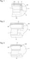
- FIG. 1 schematically represents a partial cross-sectional view of a first exemplary embodiment of a timepiece 10 comprising an anti-fog device 100 according to the invention.
- the timepiece 10 such as a wristwatch, is intended to be worn in contact with the user's skin, for example on the wrist.
- the timepiece 10 comprises a caseband 11, intended to receive a timepiece movement 1.
- the clockwork movement 1 may be a mechanical, electromechanical or electronic movement.
- the clockwork movement 1 is a mechanical movement.
- the case 11 is closed in the lower part by a back 12 and in the upper part by a protective glass 13, so as to protect the clock movement 1.
- the timepiece 10 also includes a flexible or articulated bracelet (not shown), two ends of which are intended to be coupled, for example in a removable manner, to the caseband 11, via an ad hoc fastening system which will not be detailed in the present application, allowing the user to wear the timepiece 10, for example on the wrist, and to have the outer surface of the back cover 12 in contact with the wearer's skin.
- a flexible or articulated bracelet (not shown), two ends of which are intended to be coupled, for example in a removable manner, to the caseband 11, via an ad hoc fastening system which will not be detailed in the present application, allowing the user to wear the timepiece 10, for example on the wrist, and to have the outer surface of the back cover 12 in contact with the wearer's skin.
- the bottom 12 has at least one part 12a made of a heat-conducting material, for example based on metal and/or ceramic and/or polymer loaded with carbon fibers. This part 12a is arranged to be in contact with the skin of the wearer.
- the base 12 is made entirely of a heat-conducting material, preferably of a material based on metal and/or ceramic and/or polymer loaded with carbon fibers.
- a thermally conductive material is considered to have a thermal conductivity greater than or equal to 1 W/m.K (Watt/meter.Kelvin).
- the bottom 12, or at least the part 12a of the bottom 12, is made of a thermally conductive material having a thermal conductivity greater than 10 W/m.K.
- the timepiece 10 also includes an anti-fog device 100 for said protective glass 13 making it possible to prevent the formation of fog on the internal surface of the protective glass 13, i.e. the surface facing the timepiece movement 1, or to limit/reduce the presence of visible fog following a significant thermal shock.
- the anti-fog device 100 comprises a layer of transparent conductive oxides 105 (TCO, for Transparent Conductive Oxide in English) arranged directly at least on a portion of the internal surface of the protective glass 13.
- TCO transparent conductive oxides 105
- the layer of transparent conductive oxides 105 is provided over the entire internal surface of the protective glass 13.
- the layer of transparent conductive oxides 105 is provided on a portion of the internal surface of the protective glass 13, this must be sufficiently extensive to ensure that the protective glass 13 is heated and to prevent the formation of fog.
- This layer of transparent conductive oxides 105 has thermal and conduction properties which are used in the anti-fog device 100 according to the invention.
- the layer of transparent conductive oxides is deposited on the protective glass 13 by a chemical vapor deposition (CVD) method or by a physical vapor deposition (PVD) method.
- CVD chemical vapor deposition
- PVD physical vapor deposition
- other methods of depositing thin layers known to those skilled in the art are also possible.
- the layer of transparent conductive oxides 105 is for example composed of tin-doped indium oxide, aluminum-doped zinc oxide, zinc oxide, or even fluorine-doped tin dioxide.
- the anti-fog device 100 also comprises a thermal interface member 106 arranged in the caseband 11 and configured to bring the layer of transparent conductive oxides 105 into thermal contact by conduction with the bottom 12, or at least with the part 12a made of thermally conductive material of the bottom 12, if the latter is not entirely made of thermally conductive material.
- the thermal interface member 106 may be configured to contact thermal, by conduction, the layer of transparent conductive oxides 105 with the middle part 11, if the latter is made of a thermally conductive material, the middle part 11 then ensuring a thermal exchange with the bottom 12, or the part 12a of the bottom 12, in thermally conductive material.
- the thermal interface member 106 can be made of a material promoting heat exchange by conduction while being electrically insulating.
- the thermal interface member 106 is for example a thermally conductive pad having a thermal conductivity greater than or equal to 1 W/m.K, preferably greater than 2 W/m.K.
- the thermal interface member 106 is arranged in a housing of the case 11, for example via a positioning system.
- Such a positioning system may for example comprise a thermally insulating element, or be entirely in a thermally insulating material, so as to favor thermal conduction between the bottom 12 and the layer of transparent conductive oxides 105, while thermally insulating the thermal interface member 106 from the caseband 11 to avoid thermal losses by conduction with the caseband 11 in contact with the external environment.
- the thermal interface member 106 is for example a thermally conductive pad composed of one or more polymer(s), for example elastomer, and metallic, ceramic, carbon-based particles and/or carbon fibers, or a mixture of these particles and/or these fibers.
- the thermal interface member 106 is for example a thermally conductive pad composed of silicone and metal and/or ceramic particles.
- the thermal interface member 106 is for example a thermally conductive pad of annular shape to be in contact with the layer of transparent conductive oxides 105 at a peripheral edge of the protective glass 13 and the bottom.
- the thermal interface member 106 may be formed by a plurality of thermally conductive pads distributed inside the caseband 11, to create several points of thermal conduction between the bottom 12, the part 12a of the bottom 12, or the caseband 11, and the layer of transparent conductive oxides 105.
- a seal 17 can be provided between the protective glass 13 and the caseband 11 to ensure watertightness of the timepiece 10.
- the anti-fog device 100 makes it possible to create passive heating by conduction of the protective glass 13 using the body heat of the wearer when the timepiece 10 is worn.
- the bottom 12 which is thermally conductive and in contact with the wearer's skin allows a thermal exchange by “direct” conduction with the thermal interface member 106 when the latter is in contact with the bottom 12, or a thermal exchange by “indirect” conduction with the thermal interface member 106, via the middle 11 made of thermally conductive material, when the thermal interface member 106 is in contact only with the middle 11.
- the thermal interface member 106 also ensures a thermal exchange by conduction with the layer of transparent conductive oxides 105 in order to eliminate the cold spot which may exist at the level of the protective glass 13.
- the cold spot is no longer located on the protective glass 13. Consequently, fog, if it must form, will form elsewhere in a cold zone not visible to the wearer, for example under the dial.
- FIG. 3 illustrates a second exemplary embodiment of the invention.
- the thermal interface member 106' is a thermally conductive elastomer seal positioned between the protective glass 13 and the caseband 11, which is necessarily made of thermally conductive material or composed of a thermally conductive inner part in this second exemplary embodiment in order to be able to exchange heat with the bottom 12 or the part 12a of the bottom made of thermally conductive material.
- the thermal interface member 106' also ensures watertightness between the protective glass 13 and the case 11.
- the thermally conductive elastomer seal forming the thermal interface member 106' is for example an elastomer based on silicone or fluorosilicone.
- the thermally conductive elastomer seal forming the thermal interface member 106' is for example loaded with metallic material (for example aluminum), carbon (for example graphite), ceramic material or a mixture of these materials.
Landscapes
- Physics & Mathematics (AREA)
- General Physics & Mathematics (AREA)
- Chemical & Material Sciences (AREA)
- Crystallography & Structural Chemistry (AREA)
- Engineering & Computer Science (AREA)
- Thermal Sciences (AREA)
- Microelectronics & Electronic Packaging (AREA)
- Power Engineering (AREA)
- Electric Clocks (AREA)
Abstract
Description
- La présente invention concerne une pièce d'horlogerie comportant une glace de protection présentant un dispositif antibuée pour éviter ou limiter la formation de buée, ou de fines gouttelettes d'eau, à la surface interne de la glace de protection.
- Les pièces d'horlogerie sont portées au quotidien dans des environnements très variables en terme d'humidité relative, de pression et de température. Une pièce d'horlogerie empêche structurellement l'humidité de pénétrer dans le corps principal, mais elle subit des échanges gazeux entre l'intérieur du corps principal et l'ambiance extérieure, et ce, malgré une étanchéité à l'eau assurée.
- Cet échange gazeux, appelé perméation, se passe au travers des joints qui sont majoritairement en matériaux polymères dont la propriété de perméation est variable, mais jamais nulle. Il arrive donc régulièrement que dans des environnements très chauds et humides, de la vapeur d'eau pénètre dans une pièce d'horlogerie, ce qui en soit n'est pas un problème car invisible pour l'utilisateur tant qu'il n'y a pas de buée visible sur la face interne de la glace de protection.
- La buée se forme le plus souvent au moment où la température vue par le porteur s'abaisse, par exemple en se baignant ou en entrant dans un environnement climatisé dans lequel la température est plusieurs degrés plus basse que précédemment. La glace de protection étant le point le plus en contact avec l'environnement extérieur, de fines gouttelettes d'eau formées par condensation adhèrent naturellement sur la surface interne de la glace de protection. Le porteur constate la présence de buée à l'intérieur de la pièce d'horlogerie et pense alors souvent, mais à tort, que son produit n'est plus étanche à l'eau. Ce phénomène est source de nombreux retours de marché, mais aussi de perte de confiance des usagers, et donc de dégradation d'image pour la marque horlogère.
- Il existe des traitements hydrophiles consistant en l'application d'un agent tensioactif sur la surface interne de la glace de protection afin d'éviter l'adhérence de fines gouttelettes d'eau sur la surface de la glace de protection. En effet, ces couches hydrophiles permettent à l'eau de s'étaler sur toute la surface interne de la glace de protection et reste donc invisible par le porteur. Cependant, ces couches hydrophiles ne sont pas toujours compatibles avec une esthétique de qualité (coloration, effet diffusant, etc).
- Il existe une autre méthode basée sur le principe d'absorption de l'eau contenue dans la vapeur pénétrant dans la pièce d'horlogerie. Toutefois, ces solutions sont limitées dans le temps et les capacités d'absorption sont limitées (en quantité). Par conséquent, ces solutions ne sont pas entièrement satisfaisantes.
- Il existe donc un besoin d'amélioration de la capacité antibuée des glaces de protection et des pièces d'horlogerie équipées de telles glaces de protection.
- A cette fin, la présente invention propose une solution pour répondre aux problématiques de l'état de la technique en proposant une pièce d'horlogerie munie d'une glace de protection comportant un dispositif antibuée transparent, présentant une excellente capacité antibuée permettant d'empêcher la formation de buée dans divers environnements d'utilisation, dont l'efficacité n'est pas limitée dans le temps et qui n'est pas limité par une capacité maximale d'absorption.
- Dans ce contexte, l'invention propose une pièce d'horlogerie comportant une carrure dans laquelle un mouvement d'horlogerie est logé, la carrure étant fermée par un fond et par une glace de protection, ladite pièce d'horlogerie étant caractérisée en ce qu'elle comporte un dispositif antibuée de ladite glace de protection, ledit dispositif antibuée comportant :
- une couche d'oxydes transparents conducteurs ménagée au moins sur une portion d'une surface interne de la glace de protection ;
- un organe d'interface thermique, présentant une conductivité thermique supérieure ou égale à 1 W/m.K, ménagé dans ladite carrure et configuré pour :
- a) assurer un échange thermique par contact entre ladite couche d'oxyde conducteur et la carrure, la carrure et ledit fond étant réalisés dans une matière thermoconductrice, ou
- b) assurer un échanger thermique par contact entre ladite couche d'oxyde conducteur et le fond, ledit fond comportant au moins une partie réalisée dans une matière thermoconductrice en contact avec ledit organe d'interface thermique.
- Le dispositif antibuée selon l'invention permet de créer un chauffage passif de la glace de protection en utilisation les propriétés de conduction thermique de la couche d'oxydes transparents conducteurs et en mettant en contact celle-ci avec le fond en matière thermoconductrice pour bénéficier de la chaleur corporelle du porteur lorsque la pièce d'horlogerie est portée. Ainsi, la glace de protection n'est plus le point froid de la pièce d'horlogerie.
- Un tel dispositif antibuée n'est donc pas limité dans le temps et sa capacité à éviter la formation de buée n'est pas limitée.
- Le fond qui est thermoconducteur et en contact avec la peau du porteur permet un échange thermique par conduction « directe » avec l'organe d'interface thermique lorsque celui-ci est en contact avec le fond, ou un échange thermique par conduction « indirecte » avec l'organe d'interface thermique, via la carrure 11 en matière thermoconductrice, lorsque l'organe d'interface thermique est en contact uniquement avec la carrure.
- Outre les caractéristiques évoquées dans le paragraphe précédent, la pièce d'horlogerie selon l'invention peut présenter une ou plusieurs caractéristiques complémentaires parmi les suivantes, considérées individuellement ou selon toutes les combinaisons techniquement possibles :
- la couche d'oxydes transparents conducteurs est composée d'oxyde d'indium dopé à l'étain, d'oxyde de zinc dopé à l'aluminium, d'oxyde de zinc, ou encore de dioxyde d'étain dopé au fluor ;
- l'organe conducteur thermique est un joint élastomère thermoconducteur ménagée entre la carrure et la glace de protection ;
- le joint élastomère thermoconducteur est en élastomère à base de silicone ou de fluorosilicone ;
- le joint élastomère thermoconducteur assure l'étanchéité de la carrure au niveau de la glace de protection ;
- l'organe d'interface thermique est un tampon thermoconducteur logé dans un logement de la carrure ;
- le tampon thermoconducteur est composé d'un ou plusieurs polymère(s) et de particules métalliques, céramiques, à base de carbone et/ou de fibres de carbone, ou d'un mélange de ces particules et/ou de ces fibres ;
- le tampon thermoconducteur est composé d'élastomère, préférentiellement du silicone, et de particules en céramique ;
- l'organe d'interface thermique est formé par une pluralité de tampons conducteurs ;
- l'organe d'interface thermique présente une forme annulaire.
- Selon une première variante de réalisation de l'invention, l'organe d'interface thermique est un tampon thermoconducteur ménagé dans la carrure, l'organe d'interface thermique étant en contact avec la couche d'oxydes transparents conducteurs et au moins une partie du fond pour assurer un échange thermique par conduction entre la couche d'oxyde conducteur et le fond.
- Dans cette première variante de réalisation de l'invention, la pièce d'horlogerie peut comporter en outre un système de positionnement de l'organe d'interface thermique réalisé au moins en partie dans une matière isolante thermiquement et configuré pour assurer une conduction thermique entre le fond et la couche d'oxyde conducteur tout en isolant thermiquement l'organe d'interface thermique de la carrure.
- Selon une deuxième variante de réalisation de l'invention, l'organe d'interface thermique est un tampon thermoconducteur ménagé dans la carrure, l'organe d'interface thermique étant en contact avec la couche d'oxydes transparents conducteurs et la carrure pour assurer un échange thermique par conduction entre la couche d'oxyde conducteur et la carrure. La carrure et le fond sont en matière thermoconductrice de sorte qu'un échange thermique par conduction est assuré entre la carrure et le fond.
- Dans cette deuxième variante de réalisation, la carrure peut comporter un insert isolant thermiquement permettant d'empêcher un échange thermique par conduction puis convection entre l'environnement extérieure et l'organe d'interface thermique, via la carrure.
- Les buts, avantages et caractéristiques de la présente invention apparaîtront à la lecture de la description détaillée ci-dessous faisant référence aux figures suivantes :
- la
figure 1 représente schématiquement une vue partielle en coupe d'un premier exemple de réalisation d'une pièce d'horlogerie comportant un dispositif antibuée selon l'invention ; - la
figure 2 représente schématiquement une alternative de réalisation du premier exemple de réalisation illustré à lafigure 1 ; - la
figure 3 représente schématiquement une vue partielle en coupe d'un deuxième exemple de réalisation d'une pièce d'horlogerie comportant un dispositif antibuée selon l'invention. - Dans toutes les figures, les éléments communs portent les mêmes numéros de référence sauf précision contraire.
- La
figure 1 représente schématiquement une vue partielle en coupe d'un premier exemple de réalisation d'une pièce d'horlogerie 10 comportant un dispositif antibuée 100 selon l'invention. - La pièce d'horlogerie 10, telle qu'une montre bracelet, est destinée à être portée au contact de la peau de l'utilisateur, par exemple au poignet.
- La pièce d'horlogerie 10 comporte une carrure 11, destinée à recevoir un mouvement d'horlogerie 1.
- Le mouvement d'horlogerie 1 peut être un mouvement mécanique, électromécanique ou encore électronique. Préférentiellement, le mouvement d'horlogerie 1 est un mouvement mécanique.
- La carrure 11 est fermée en partie inférieure par un fond 12 et en partie supérieure par une glace de protection 13, de manière à protéger le mouvement d'horlogerie 1.
- La pièce d'horlogerie 10 comporte également un bracelet (non représenté) souple ou articulé dont deux extrémités sont destinées à être couplées, par exemple de manière amovible, à la carrure 11, via un système de fixation ad hoc qui ne sera pas détaillé dans la présente demande, permettant à l'utilisateur de porter la pièce d'horlogerie 10, par exemple au poignet, et d'avoir la surface extérieure du fond 12 en contact avec la peau du porteur.
- Le fond 12 présente au moins une partie 12a réalisée dans une matière thermoconductrice, par exemple à base métallique et/ou céramique et/ou polymère chargé de fibres de carbone. Cette partie 12a est agencée pour être en contact avec la peau du porteur.
- Préférentiellement, le fond 12 est réalisée intégralement dans une matière thermoconductrice, préférentiellement dans une matière à base métallique et/ou céramique et/ou polymère chargé de fibres de carbone.
- De manière générale, dans la présente demande, on considère une matière thermoconductrice lorsqu'elle présente une conductivité thermique supérieure ou égale à 1 W/m.K (Watt/mètre.Kelvin).
- Préférentiellement, le fond 12, ou au moins la partie 12a du fond 12, est réalisé(e) dans une matière thermoconductrice présentant une conductivité thermique supérieure à 10 W/m.K.
- La pièce d'horlogerie 10 comporte également un dispositif antibuée 100 de ladite glace de protection 13 permettant d'éviter la formation de buée sur la surface interne de la glace de protection 13, c'est-à-dire la surface en regard avec le mouvement d'horlogerie 1 ou de limiter/réduire la présence de buée visible suite à un choc thermique important.
- A cet effet, le dispositif antibuée 100 comporte une couche d'oxydes transparents conducteurs 105 (TCO, pour Transparent Conductive Oxide en langue anglaise) ménagée directement au moins sur une portion de la surface interne de la glace de protection 13.
- Avantageusement, la couche d'oxydes transparents conducteurs 105 est ménagée sur toute la surface interne de la glace de protection 13.
- Si la couche d'oxydes transparents conducteurs 105 est ménagée sur une portion de la surface interne de la glace de protection 13, celle-ci doit être suffisamment étendue pour assurer une mise en température de la glace de protection 13 et éviter la formation de buée.
- Cette couche d'oxydes transparents conducteurs 105 présente des propriétés thermiques et de conduction qui sont utilisées dans le dispositif antibuée 100 selon l'invention.
- Préférentiellement, la couche d'oxydes transparents conducteurs est déposée sur la glace de protection 13 par une méthode de dépôt chimique en phase vapeur (CVD) ou par une méthode de dépôt physique en phase vapeur (PVD). Toutefois, d'autres méthodes de dépôt de couches minces connues de l'homme du métier sont également possibles.
- La couche d'oxydes transparents conducteurs 105 est par exemple composée d'oxyde d'indium dopé à l'étain, d'oxyde de zinc dopé à l'aluminium, d'oxyde de zinc, ou encore de dioxyde d'étain dopé au fluor..
- Le dispositif antibuée 100 comporte également un organe d'interface thermique 106 ménagé dans la carrure 11 et configuré pour mettre en contact thermique par conduction la couche d'oxydes transparents conducteurs 105 avec le fond 12, ou au moins avec la partie 12a en matière thermoconductrice du fond 12, si celui-ci n'est pas entièrement réalisé en matière thermoconductrice.
- Selon une alternative de réalisation illustrée à la
figure 2 , l'organe d'interface thermique 106 peut être configuré pour mettre en contact thermique, par conduction, la couche d'oxydes transparents conducteurs 105 avec la carrure 11, si celle-ci est réalisée dans une matière thermoconductrice, la carrure 11 assurant alors un échange thermique avec le fond 12, ou la partie 12a du fond 12, en matière thermoconductrice. - Selon les besoins, l'organe d'interface thermique 106 peut être réalisé dans une matière favorisant les échanges thermiques par conduction tout en étant isolant électriquement.
- L'organe d'interface thermique 106 est par exemple un tampon thermoconducteur présentant une conductivité thermique supérieure ou égale à 1 W/m.K, préférentiellement supérieure à 2 W/m.K.
- L'organe d'interface thermique 106 est ménagé dans un logement de la carrure 11, par exemple via un système de positionnement.
- Un tel système de positionnement peut par exemple comporter un élément isolant thermiquement, ou être totalement dans une matière isolante thermiquement, de manière à privilégier la conduction thermique entre le fond 12 et la couche d'oxydes transparents conducteurs 105, tout en isolant thermiquement l'organe d'interface thermique 106 de la carrure 11 pour éviter des déperditions thermiques par conduction avec la carrure 11 en contact avec l'environnement extérieur.
- L'organe d'interface thermique 106 est par exemple un tampon thermoconducteur composé d'un ou de plusieurs polymère(s), par exemple d'élastomère, et de particules métalliques, céramiques, à base de carbone et/ou de fibres de carbone, ou d'un mélange de ces particules et/ou de ces fibres.
- L'organe d'interface thermique 106 est par exemple un tampon thermoconducteur composé de silicone et de particules métalliques et/ou céramiques.
- L'organe d'interface thermique 106 est par exemple un tampon thermoconducteur de forme annulaire pour être en contact avec la couche d'oxydes transparents conducteurs 105 au niveau d'un pourtour périphérique de la glace de protection 13 et du fond.
- L'organe d'interface thermique 106 peut être formé par une pluralité de tampons thermoconducteurs répartis à l'intérieur de la carrure 11, pour créer plusieurs points de conduction thermique entre le fond 12, la partie 12a du fond 12, ou la carrure 11, et la couche d'oxydes transparents conducteurs 105.
- Comme illustré à la
figure 1 , une joint d'étanchéité 17 peut être ménagé entre la glace de protection 13 et la carrure 11 pour assurer une étanchéité à l'eau de la pièce d'horlogerie 10. - Le dispositif antibuée 100 selon l'invention permet de créer un chauffage passif par conduction de la glace de protection 13 en utilisant la chaleur corporelle du porteur lorsque la pièce d'horlogerie 10 est portée.
- Le fond 12 qui est thermoconducteur et en contact avec la peau du porteur permet un échange thermique par conduction « directe » avec l'organe d'interface thermique 106 lorsque celui-ci est en contact avec le fond 12, ou un échange thermique par conduction « indirecte » avec l'organe d'interface thermique 106, via la carrure 11 en matière thermoconductrice, lorsque l'organe d'interface thermique 106 est en contact uniquement avec la carrure 11.
- L'organe d'interface thermique 106 assure également un échange thermique par conduction avec la couche d'oxydes transparents conducteurs 105 afin d'éliminer le point froid pouvant exister au niveau de la glace de protection 13.
- Grâce à l'invention, le point froid n'est plus situé sur la glace de protection 13. Par conséquent, la buée, si elle doit se former, se formera ailleurs dans une zone froide non visible par le porteur, par exemple sous le cadran.
- La
figure 3 illustre un deuxième exemple de réalisation de l'invention. - Dans ce deuxième exemple de réalisation, l'organe d'interface thermique 106' est un joint élastomère thermoconducteur positionné entre la glace de protection 13 et la carrure 11, qui est obligatoirement en matière thermoconductrice ou composée d'une partie intérieure thermoconductrice dans ce deuxième exemple de réalisation pour pouvoir échanger thermiquement avec le fond 12 ou la partie 12a du fond en matière thermoconductrice.
- Dans ce deuxième exemple de réalisation, l'organe d'interface thermique 106' assure également une étanchéité à l'eau entre la glace de protection 13 et la carrure 11.
- Le joint élastomère thermoconducteur formant l'organe d'interface thermique 106' est par exemple un élastomère à base de silicone ou de fluorosilicone.
- Le joint élastomère thermoconducteur formant l'organe d'interface thermique 106' est par exemple chargé en matière métallique (par exemple aluminium), en carbone (par exemple graphite), en matière céramique ou par un mélange de ces matières.
Claims (11)
- Pièce d'horlogerie (10) comportant une carrure (11) fermée par un fond (12) et par une glace de protection (13), ladite pièce d'horlogerie (10) étant caractérisée en ce qu'elle comporte un dispositif antibuée (100) de ladite glace de protection (13), ledit dispositif antibuée (100) comportant :- une couche d'oxydes transparents conducteurs (105) ménagée au moins sur une portion d'une surface interne de la glace de protection (13) ;- un organe d'interface thermique (106), présentant une conductivité thermique supérieure ou égale à 1 W/m.K, ménagé dans ladite carrure (11) et configuré pour :a) assurer un échange thermique par contact entre ladite couche d'oxyde conducteur (105) et la carrure (11), la carrure (11) et ledit fond (12) étant réalisés dans une matière thermoconductrice, oub) assurer un échange thermique par contact entre ladite couche d'oxyde conducteur (105) et le fond (12), ledit fond (12) comportant au moins une partie (12a) réalisée dans une matière thermoconductrice en contact avec ledit organe d'interface thermique (106).
- Pièce d'horlogerie (10) selon la revendication précédente caractérisée en ce que la couche d'oxydes transparents conducteurs (105) est composée d'oxyde d'indium dopé à l'étain, d'oxyde de zinc dopé à l'aluminium, d'oxyde de zinc, ou encore de dioxyde d'étain dopé au fluor.
- Pièce d'horlogerie (10) selon l'une des revendications précédentes caractérisée en ce que l'organe conducteur thermique (106) est un joint élastomère thermoconducteur ménagée entre la carrure (11) et la glace de protection (13).
- Pièce d'horlogerie (10) selon la revendication précédente caractérisée en ce que le joint élastomère thermoconducteur est en élastomère à base de silicone ou de fluorosilicone.
- Pièce d'horlogerie (10) selon la revendication précédente caractérisée en ce que le joint élastomère thermoconducteur assure l'étanchéité de la carrure (11) au niveau de la glace de protection (13).
- Pièce d'horlogerie (10) selon l'une des revendications précédentes caractérisée en ce que l'organe d'interface thermique (106) est un tampon thermoconducteur logé dans un logement de la carrure (11).
- Pièce d'horlogerie (10) selon la revendication précédente caractérisée en ce que le tampon thermoconducteur est composé d'une base en polymère et de particules métalliques, céramiques, à base de carbone et/ou de fibres de carbone, ou d'un mélange de ces particules et/ou de ces fibres.
- Pièce d'horlogerie (10) selon la revendication précédente caractérisée en ce que le tampon thermoconducteur est composé d'une base en élastomère, préférentiellement à base de silicone et de particules en céram ique.
- Pièce d'horlogerie (10) selon l'une des revendications 6 à 8 caractérisée en ce que l'organe d'interface thermique (106) est formé par une pluralité de tampons conducteurs.
- Pièce d'horlogerie (10) selon l'une des revendications 6 à 8 caractérisée en ce que l'organe d'interface thermique (106) présente une forme annulaire.
- Pièce d'horlogerie (10) selon l'une des revendications précédentes caractérisée en ce qu'elle comporte un système de positionnement l'organe d'interface thermique (106) configuré pour assurer une conduction thermique entre le fond (12) et la couche d'oxyde conducteur (105) tout en isolant thermiquement l'organe d'interface thermique (106) de la carrure (11).
Priority Applications (4)
| Application Number | Priority Date | Filing Date | Title |
|---|---|---|---|
| EP23184370.7A EP4492159A1 (fr) | 2023-07-10 | 2023-07-10 | Pièce d'horlogerie comportant une glace de protection avec un dispositif antibuée |
| US18/664,385 US20250021054A1 (en) | 2023-07-10 | 2024-05-15 | Timepiece comprising a protective glass with an anti-fogging device |
| JP2024091950A JP7703745B2 (ja) | 2023-07-10 | 2024-06-06 | 防曇デバイス付き保護ガラスを備えた計時器 |
| CN202410922170.9A CN119292028A (zh) | 2023-07-10 | 2024-07-10 | 具有防起雾装置的包括保护玻璃的计时器 |
Applications Claiming Priority (1)
| Application Number | Priority Date | Filing Date | Title |
|---|---|---|---|
| EP23184370.7A EP4492159A1 (fr) | 2023-07-10 | 2023-07-10 | Pièce d'horlogerie comportant une glace de protection avec un dispositif antibuée |
Publications (1)
| Publication Number | Publication Date |
|---|---|
| EP4492159A1 true EP4492159A1 (fr) | 2025-01-15 |
Family
ID=87202164
Family Applications (1)
| Application Number | Title | Priority Date | Filing Date |
|---|---|---|---|
| EP23184370.7A Pending EP4492159A1 (fr) | 2023-07-10 | 2023-07-10 | Pièce d'horlogerie comportant une glace de protection avec un dispositif antibuée |
Country Status (4)
| Country | Link |
|---|---|
| US (1) | US20250021054A1 (fr) |
| EP (1) | EP4492159A1 (fr) |
| JP (1) | JP7703745B2 (fr) |
| CN (1) | CN119292028A (fr) |
Citations (4)
| Publication number | Priority date | Publication date | Assignee | Title |
|---|---|---|---|---|
| CH577207B5 (fr) * | 1970-08-17 | 1976-06-30 | Suwa Seikosha Kk | |
| EP0006077A2 (fr) * | 1978-06-02 | 1979-12-12 | Montres Rado S.A. | Boîte de montre étanche à verre polygonal plat, amovible |
| CH703966B1 (fr) * | 2010-10-27 | 2015-04-15 | Swatch Group Res & Dev Ltd | Glace servant à fermer par le haut la boîte d'un objet portable. |
| EP3196678A1 (fr) * | 2016-01-19 | 2017-07-26 | Seiko Epson Corporation | Élément transmettant la lumière, pièce d'horlogerie et procédé de production d'un élément transmettant la lumière |
Family Cites Families (6)
| Publication number | Priority date | Publication date | Assignee | Title |
|---|---|---|---|---|
| JPS62130374A (ja) * | 1985-12-03 | 1987-06-12 | Citizen Watch Co Ltd | 腕時計用内装部品 |
| JP2011158403A (ja) | 2010-02-02 | 2011-08-18 | Seiko Epson Corp | 時計用カバーガラス、時計、および時計用カバーガラスの防曇処理方法 |
| CN103370948B (zh) | 2011-02-07 | 2016-02-17 | 京瓷株式会社 | 装饰品用构件及具备该装饰品用构件的装饰品 |
| JP6780416B2 (ja) | 2016-01-19 | 2020-11-04 | セイコーエプソン株式会社 | 透光性部材、時計、および透光性部材の製造方法 |
| JP6772632B2 (ja) * | 2016-07-29 | 2020-10-21 | セイコーエプソン株式会社 | 携帯型電子機器 |
| JP2018044869A (ja) * | 2016-09-15 | 2018-03-22 | カシオ計算機株式会社 | 表示装置及び時計 |
-
2023
- 2023-07-10 EP EP23184370.7A patent/EP4492159A1/fr active Pending
-
2024
- 2024-05-15 US US18/664,385 patent/US20250021054A1/en active Pending
- 2024-06-06 JP JP2024091950A patent/JP7703745B2/ja active Active
- 2024-07-10 CN CN202410922170.9A patent/CN119292028A/zh active Pending
Patent Citations (4)
| Publication number | Priority date | Publication date | Assignee | Title |
|---|---|---|---|---|
| CH577207B5 (fr) * | 1970-08-17 | 1976-06-30 | Suwa Seikosha Kk | |
| EP0006077A2 (fr) * | 1978-06-02 | 1979-12-12 | Montres Rado S.A. | Boîte de montre étanche à verre polygonal plat, amovible |
| CH703966B1 (fr) * | 2010-10-27 | 2015-04-15 | Swatch Group Res & Dev Ltd | Glace servant à fermer par le haut la boîte d'un objet portable. |
| EP3196678A1 (fr) * | 2016-01-19 | 2017-07-26 | Seiko Epson Corporation | Élément transmettant la lumière, pièce d'horlogerie et procédé de production d'un élément transmettant la lumière |
Also Published As
| Publication number | Publication date |
|---|---|
| JP7703745B2 (ja) | 2025-07-07 |
| US20250021054A1 (en) | 2025-01-16 |
| JP2025011029A (ja) | 2025-01-23 |
| CN119292028A (zh) | 2025-01-10 |
Similar Documents
| Publication | Publication Date | Title |
|---|---|---|
| EP4012510B1 (fr) | Dispositif horloger isotherme | |
| FR2491218A1 (fr) | Detecteur a scintillations monte dans un boitier hermetique | |
| EP4012512B1 (fr) | Boitier d'un dispositif de dewar comprenant un élément de liaison d'une boite de montre | |
| CH720930A2 (fr) | Pièce d'horlogerie comportant une glace de protection avec un dispositif antibuée | |
| EP2672134B1 (fr) | Dispositif d'étanchéité de roulement de grande dimension | |
| EP0199207B1 (fr) | Montre-bracelet dont certaines de ses parties sont recouvertes d'un matériau extra-dur | |
| CH678254B5 (fr) | ||
| EP0168010B1 (fr) | Boîte de montre | |
| CH674292B5 (fr) | ||
| EP4105737B1 (fr) | Dispositif de dewar pour montre comprenant un dispositif d'actionnement | |
| CH718146A2 (fr) | Dispositif de Dewar pour des composants d'une montre. | |
| JP7703745B2 (ja) | 防曇デバイス付き保護ガラスを備えた計時器 | |
| EP4105736B1 (fr) | Dispositif de dewar pour montre comprenant un dispositif d'actionnement | |
| WO2004046831A1 (fr) | Boite de montre | |
| EP0913648A1 (fr) | Dispositif compensateur de dilatation et fenêtres ou similaires d'appareils de chauffage munies d'un tel dispositif | |
| CH709079A2 (fr) | Boîte de montre. | |
| EP3736641B1 (fr) | Tige-couronne d'une boîte de montre étanche, et boîte de montre la comprenant | |
| FR2752959A1 (fr) | Dispositif pour permettre a un boitier de montre etanche contenant du liquide de resister a de fortes variations de temperature et de pression | |
| EP4150410A1 (fr) | Boite de montre comprenant un élément tournant | |
| CH571964A5 (fr) | ||
| EP1102136A1 (fr) | Dispositif d'assemblage d'une coiffe en matériau dur sur la carrure d'une montre | |
| EP4492162B1 (fr) | Pièce d'horlogerie à commande tactile comportant un dispositif antibuée | |
| FR2490031A1 (fr) | Dispositif a laser | |
| CH718144A2 (fr) | Dispositif horloger isotherme. | |
| EP3828645B1 (fr) | Montre squelette |
Legal Events
| Date | Code | Title | Description |
|---|---|---|---|
| PUAI | Public reference made under article 153(3) epc to a published international application that has entered the european phase |
Free format text: ORIGINAL CODE: 0009012 |
|
| STAA | Information on the status of an ep patent application or granted ep patent |
Free format text: STATUS: THE APPLICATION HAS BEEN PUBLISHED |
|
| AK | Designated contracting states |
Kind code of ref document: A1 Designated state(s): AL AT BE BG CH CY CZ DE DK EE ES FI FR GB GR HR HU IE IS IT LI LT LU LV MC ME MK MT NL NO PL PT RO RS SE SI SK SM TR |
|
| P01 | Opt-out of the competence of the unified patent court (upc) registered |
Free format text: CASE NUMBER: APP_6838/2025 Effective date: 20250210 |
|
| STAA | Information on the status of an ep patent application or granted ep patent |
Free format text: STATUS: REQUEST FOR EXAMINATION WAS MADE |
|
| 17P | Request for examination filed |
Effective date: 20250701 |