EP4492020A1 - Vorrichtung zur polarisationsbeurteilung - Google Patents
Vorrichtung zur polarisationsbeurteilung Download PDFInfo
- Publication number
- EP4492020A1 EP4492020A1 EP22931029.7A EP22931029A EP4492020A1 EP 4492020 A1 EP4492020 A1 EP 4492020A1 EP 22931029 A EP22931029 A EP 22931029A EP 4492020 A1 EP4492020 A1 EP 4492020A1
- Authority
- EP
- European Patent Office
- Prior art keywords
- polarization
- correction coefficient
- images
- observation target
- unit
- Prior art date
- Legal status (The legal status is an assumption and is not a legal conclusion. Google has not performed a legal analysis and makes no representation as to the accuracy of the status listed.)
- Pending
Links
Images


Classifications
-
- G—PHYSICS
- G01—MEASURING; TESTING
- G01J—MEASUREMENT OF INTENSITY, VELOCITY, SPECTRAL CONTENT, POLARISATION, PHASE OR PULSE CHARACTERISTICS OF INFRARED, VISIBLE OR ULTRAVIOLET LIGHT; COLORIMETRY; RADIATION PYROMETRY
- G01J4/00—Measuring polarisation of light
- G01J4/04—Polarimeters using electric detection means
-
- G—PHYSICS
- G01—MEASURING; TESTING
- G01N—INVESTIGATING OR ANALYSING MATERIALS BY DETERMINING THEIR CHEMICAL OR PHYSICAL PROPERTIES
- G01N21/00—Investigating or analysing materials by the use of optical means, i.e. using sub-millimetre waves, infrared, visible or ultraviolet light
- G01N21/17—Systems in which incident light is modified in accordance with the properties of the material investigated
- G01N21/21—Polarisation-affecting properties
-
- G—PHYSICS
- G01—MEASURING; TESTING
- G01N—INVESTIGATING OR ANALYSING MATERIALS BY DETERMINING THEIR CHEMICAL OR PHYSICAL PROPERTIES
- G01N21/00—Investigating or analysing materials by the use of optical means, i.e. using sub-millimetre waves, infrared, visible or ultraviolet light
- G01N21/17—Systems in which incident light is modified in accordance with the properties of the material investigated
- G01N21/25—Colour; Spectral properties, i.e. comparison of effect of material on the light at two or more different wavelengths or wavelength bands
- G01N21/27—Colour; Spectral properties, i.e. comparison of effect of material on the light at two or more different wavelengths or wavelength bands using photo-electric detection ; circuits for computing concentration
- G01N21/274—Calibration, base line adjustment, drift correction
-
- G—PHYSICS
- G01—MEASURING; TESTING
- G01N—INVESTIGATING OR ANALYSING MATERIALS BY DETERMINING THEIR CHEMICAL OR PHYSICAL PROPERTIES
- G01N2201/00—Features of devices classified in G01N21/00
- G01N2201/12—Circuits of general importance; Signal processing
- G01N2201/121—Correction signals
Definitions
- the present invention relates to a technique for correcting an error due to the polarization characteristics of irradiation light when performing polarization distribution measurement of a target by polarized light observation.
- Patent Document 1 discloses a technique for measuring a fiber direction of a carbon fiber material of a test object using a polarization direction of light reflected by the test object by utilizing a fact that when unpolarized light strikes on a carbon fiber, light reflected by the fiber is polarized in a fiber direction.
- the polarization state information of an observation target is acquired by applying a model formula of polarization on the basis of the luminance information of polarization images in a plurality of directions obtained by imaging the observation target.
- Methods common as a method for capturing a polarization image are a method of forming polarization images in a plurality of directions by arranging a polarizer in front of an imaging unit and performing imaging while rotating the polarizer, and a method of acquiring polarization images in a plurality of directions at once using an image sensor in which blocks in which polarizers differing from each other in polarization direction are disposed in pixels are arranged in an array manner.
- Patent Document 2 discloses an image processing device, an information acquisition device, and an information acquisition method for obtaining a high-quality polarization image.
- Patent Document 3 discloses a method for the calibration of a polarizer array for improving the accuracy of measurement of birefringence and polarization characteristics.
- Patent Document 4 discloses a light receiving device that has high sensitivity but can obtain highly accurate polarization state information even if the light receiving device includes a polarizing element in which absorption components frequently leak.
- Patent Document 3 and Patent Document 4 there is a case where the polarization of an observation target cannot be evaluated with sufficient accuracy only by correcting the sensitivity variation among pixels of an image sensor.
- illumination for observation is applied to an observation target and reflected light or transmitted light from the observation target is acquired by an image sensor.
- the polarization state information of the illumination light is also observed by the image sensor, so that the accuracy of evaluation of the polarization characteristics inherent in the observation target is deteriorated.
- an object of the present invention is to provide a polarization evaluation device for performing highly accurate polarization evaluation.
- the polarization evaluation device of the present invention that solves the above problems mainly has any of the following configurations.
- processing of correcting polarization characteristics of an optical system using correction information acquired in advance is performed on a polarization image.
- polarization characteristics can be evaluated with high accuracy because only the polarization characteristics of the observation target can be evaluated.
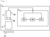
- Fig. 1 illustrates a configuration of the polarization evaluation device of the present invention.
- the polarization evaluation device 1 includes an illumination unit 2 that irradiates an observation target 10 with illumination light for observation; an imaging unit 3 that acquires polarization images in a plurality of specific directions of the reflected light from the observation target 10; and an image processing unit 4 that outputs an image of a result of evaluating polarization characteristics of the observation target 10 from the polarization images in the plurality of directions acquired by the imaging unit 3.
- the image processing unit 4 includes a correction coefficient calculation unit 4a that generates a correction coefficient for removing a polarization noise based on polarization characteristics of the optical system excluding the observation target 10; a correction coefficient storage unit 4b that stores the correction coefficient; and a polarization characteristic evaluation unit 4c that creates corrected polarization images produced from the polarization images in the plurality of directions by removing the polarization noise on the basis of the correction coefficient, and then outputs a result of evaluating the polarization characteristics of the observation target 10 from the corrected polarization images created.
- a correction coefficient calculation unit 4a that generates a correction coefficient for removing a polarization noise based on polarization characteristics of the optical system excluding the observation target 10
- a correction coefficient storage unit 4b that stores the correction coefficient
- a polarization characteristic evaluation unit 4c that creates corrected polarization images produced from the polarization images in the plurality of directions by removing the polarization noise on the basis of the correction coefficient, and then outputs a result of
- any image sensor, camera lens, or other equipment may be used.
- any illumination may be used.
- the irradiation angle of the illumination light with respect to the observation target 10 and the light incident angle from an imaging surface to the image sensor may be arbitrarily set according to the evaluation target and the purpose of the evaluation, and the present invention is not limited by the configuration of the optical system.
- the imaging unit 3 preferably has a configuration capable of acquiring polarization images in three or more directions. Hereinafter, the reason for this will be described.
- Measurement of polarization characteristics requires polarization images in a plurality of specific directions.
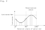
- the observation target 10 is irradiated with light from the illumination unit 2 and reflected light from the observation target 10 is imaged by the imaging unit 3 via a polarizer, the luminance of the captured image of the observation target 10 changes according to the relative phase between the polarization direction of the reflected light from the observation target 10 and the direction of the polarizer. This luminance change is indicated by a sine wave having a cycle of 180° as illustrated in Fig. 2 .
- the acquired polarization images in the three directions preferably include directions having a phase difference of 45° or more in order to maintain fitting accuracy.
- the imaging unit 3 preferably has a configuration capable of acquiring polarization images in three or more directions.
- the imaging unit 3 may be configured to use an image sensor in which blocks in which polarizers differing from each other in polarization direction are disposed in pixels are arranged in an array manner.
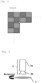
- Fig. 3 illustrates an example of an image sensor in which a plurality of blocks is arranged in an array manner, in which the blocks each include 2 ⁇ 2 pixels in which polarizers having polarization directions differing pixel by pixel (for example, four directions of 0°, 45°, 90°, and 135°) are disposed.
- imaging unit 3 may be an imaging unit 3 in which a rotatable polarizer 5 is disposed in front of a lens 3b and which is configured such that imaging is repeated with the polarizer 5 being rotated by a plurality of angles.
- Fig. 4 illustrates an example of the imaging unit 3 having a configuration in which the rotatable polarizer 5 is disposed in front of the lens 3b.
- any image sensor or configuration may be used as long as polarization images in three or more directions can be acquired.
- the light incident angle from an imaging surface of the imaging unit 3 to the image sensor may be arbitrarily arranged according to the evaluation target and the purpose of the evaluation.
- the captured polarization images in the plurality of directions are output to an image processing unit 4. These polarization images are output to a correction coefficient calculation unit 4a in the case of being used to create a correction coefficient, and are output to a polarization characteristic evaluation unit 4c in the case of being used to measure polarization characteristics, according to the purpose.
- the illumination unit 2 irradiates the observation target 10 with illumination light for observation.
- any illumination may be used because polarization characteristics derived from an optical system are acquired in advance (for example, acquired for each pixel), a correction coefficient for removing the polarization noise is created, and only the polarization characteristics derived from the observation target 10 can be evaluated.
- the irradiation angle of the illumination light with respect to the observation target 10 is not specified, and may be arbitrarily set and arranged according to the evaluation target and the evaluation contents.
- the illumination light is not particularly specified, and light having an arbitrary wavelength may be used.
- the image processing unit 4 includes a correction coefficient calculation unit 4a that generates a correction coefficient for removing a polarization noise based on polarization characteristics of the optical system excluding the observation target 10; a correction coefficient storage unit 4b that stores the correction coefficient; and a polarization characteristic evaluation unit 4c that creates corrected polarization images produced from the polarization images in the plurality of directions by removing the polarization noise on the basis of the correction coefficient, evaluates the polarization characteristics of the observation target from the corrected polarization images, and then outputs images.
- a correction coefficient calculation unit 4a that generates a correction coefficient for removing a polarization noise based on polarization characteristics of the optical system excluding the observation target 10
- a correction coefficient storage unit 4b that stores the correction coefficient
- a polarization characteristic evaluation unit 4c that creates corrected polarization images produced from the polarization images in the plurality of directions by removing the polarization noise on the basis of the correction coefficient, evaluates the polarization characteristics of the observation target from
- a polarization image is input from the imaging unit 3 to the image processing unit 4.
- This polarization image can be input to the correction coefficient calculation unit 4a in the case of being used for calculation of a correction coefficient for correcting a polarization noise of the optical system, and can be input to the polarization characteristic evaluation unit 4c in the case of being used for polarization characteristic evaluation of the observation target 10.
- Fig. 5 is a flowchart of the operation of the correction coefficient calculation unit 4a.
- Polarization images in a plurality of specific directions captured as correction images as described later are input to the correction coefficient calculation unit 4a.
- the correction coefficient calculation unit 4a calculates polarization characteristics (polarization angle and degree of polarization) of the observation target 10 from the input polarization images in the plurality of specific directions, for example, pixel by pixel and block by block. Then, a correction coefficient is calculated pixel by pixel and block by block from the calculated polarization characteristics, and the calculated correction coefficients are output to the correction coefficient storage unit 4b.
- polarization characteristics polarization angle and degree of polarization
- the calculation of the correction coefficient may be performed once for each configuration of the optical system, and the information of the calculated correction coefficient can be repeatedly used for the subsequent polarization characteristic evaluation by storing the information in the correction coefficient storage unit 4b.
- the correction image is an image obtained by imaging the correction observation target.
- the correction observation target may be any target in which the polarization direction among the polarization characteristics of the optical system and the proportion (polarization) of the polarization component of the light incident on the imaging sensor can be clarified.
- an object that is obvious to return polarized light when reflecting the observation illumination light can be used as a correction observation target.
- a plurality of polarization images obtained by imaging the correction observation target while rotating the correction observation target by a constant rotation angle may be used.
- correction polarization images polarization images in a plurality of specific directions captured by imaging an unpolarized target are used. For example, it is preferable to use an image obtained by imaging a target exhibiting uniform polarization characteristics regardless of a place, such as copy paper or a resin plate surface-treated so as to be unpolarized.
- the amount of illumination light at this time is denoted by 1.
- a sine wave that reproduces the relationship between the direction ⁇ of the polarization of the imaging unit 3 and the luminance I ⁇ is obtained pixel by pixel by performing fitting, and the angle at which the luminance takes the maximum value in the sine wave obtained by the fitting is calculated pixel by pixel as the polarization direction (polarization angle) of the reflected light from the observation target.
- the blocks each include a combination of a plurality of pixels in which polarizers differing pixel by pixel in polarization direction are disposed as illustrated in Fig.
- a polarization angle is calculated block by block from the fitting, and the results may be applied to each pixel in the blocks.
- the polarization angle may be calculated using (Equation 1) where the polarization angle is denoted by ⁇ and the luminance of each polarization image is denoted by I ⁇ .
- the polarization angle ⁇ and the degree of polarization k' of the polarization of the optical system are calculated for each pixel, and the correction information for correcting the polarization noise is calculated pixel by pixel and output to the correction information storage unit 4b.
- the optical system includes polarization characteristics
- the amount of light incident on the image sensor varies depending on the phase difference between the angular component and the polarizer of the imaging unit and the intensity of the polarization component.
- the correction coefficient is determined on the basis of the degree of polarization k' of the polarization of the optical system and the phase difference between the direction ⁇ i of the polarizer of the constituent imaging unit and the polarization angle ⁇ of the polarization of the optical system.
- the calculated pixel correction coefficient s is output to the correction information storage unit 4b.
- a target whose reflected light exhibits polarization is imaged as a correction polarization image.
- a target whose reflected light is obvious to exhibit polarization such as a resin plate with a surface hairline-processed.
- Polarization images in a plurality of specific directions are captured with the target disposed at a certain angle.
- the method of capturing the polarization images in the plurality of specific directions may be any method as long as the method can acquire polarization images in three or more directions.
- polarization images in a plurality of specific directions may be acquired by one imaging operation using an image sensor in which blocks in which polarizers differing from each other in polarization direction are disposed in pixels are arranged in an array manner.
- imaging may be repeated with the polarizer 5 being rotated by a plurality of angles.
- a polarization angle ⁇ is calculated from the calculation formula of (Equation 1).
- the target is rotated, polarization images in a plurality of specific directions are similarly captured, and a polarization angle is calculated.
- the rotation angle of the target at this time is denoted by ⁇ . This operation is repeatedly performed with the target being rotated by a plurality of angles, and the results of polarization angle calculation at every rotation angles of the object are acquired.
- the luminance I ⁇ of the polarization image for each polarization direction ⁇ of each imaging unit involves the polarization of the observation target and the polarization of the optical system
- the luminance I ⁇ ' of the polarized light of the reflected light of the observation target is determined by (Equation 8).
- k and ⁇ are variables representing the degree of polarization and the polarization angle of the optical system, respectively.
- I ⁇ ′ I ⁇ 1 + k cos ⁇ i ⁇ ⁇ 1 + k
- the polarization angle ⁇ ' is recalculated from the calculation of (Equation 1) for each rotation angle of the target.
- the variables k and ⁇ representing the degree of polarization and the polarization angle of the polarization of the optical system are determined by performing least square approximation of the difference between the rotation angle ⁇ of the target and the recalculated polarization angle ⁇ '.
- a correction coefficient for correcting the polarization noise is calculated pixel by pixel according to (Equation 7) and output to the correction information storage unit 4b.
- the correction coefficient storage unit 4b stores a correction coefficient of each pixel for removing the polarization characteristics of the optical system calculated in advance by the correction coefficient calculation unit 4a.
- the correction coefficient information stored in the correction coefficient storage unit 4b at the time of polarization characteristic evaluation is output to the polarization characteristic evaluation unit 4c.
- Fig. 6 illustrates a flowchart of the operation of the polarization characteristic evaluation unit 4c.
- Polarization images in a plurality of specific directions obtained from the imaging unit 3 of the optical system are input to the polarization characteristic evaluation unit 4c.
- the correction coefficient information of each pixel stored in the correction coefficient storage unit 4b is input.
- a corrected polarization image is created by multiplying the correction coefficients of the polarization direction and the pixel position of the corresponding imaging unit 3 obtained from the correction coefficient storage unit 4b by the luminance value of each pixel of the input polarization image.
- arbitrary polarization state information is calculated using the corrected polarization image, and the result is output.
- the calculation result may be output as an image so that the calculation result can be visually recognized.
- the polarization state information to be calculated may be any information as long as it can be calculated from a plurality of polarization images.
- the angle at which the luminance takes the maximum value in the sine wave obtained by fitting can be calculated as a polarization angle.
- the degree of polarization (the inclusion proportion of the polarization component) of the waveform obtained by fitting can also be calculated by the calculation shown in (Equation 2).
- the imaging unit 3 used was an image sensor in which blocks in which polarizers of 0°, 45°, 90°, and 135° were arranged in pixels, respectively, were arranged in an array manner.
- the illumination unit 2 used was coaxial epi-illumination with a half mirror.
- a resin plate (observation target 10) having a hairline surface and being to emit reflected light being to exhibit polarization was placed on a fine movement rotary stage 6, and imaging was performed with the resin plate being rotated from 0 to 180° in 10° increments.
- a polarization angle was measured using (Equation 1) for the captured images.
- Fig. 8 are shown the rotation angle of the fine movement rotary stage 6 before the correction of the error due to the polarization characteristics of the above-described optical system and the error with the measured polarization angle.
- a measurement error of an angle of ⁇ 5° at most occurred. This reveals that in the configuration of this optical system, there is a factor that lowers the measurement accuracy in the optical system itself.
- a conceivable factor is that light is polarized when passing through the half mirror of the illumination unit, so that the illumination light has polarization characteristics.
- a correction image was acquired using a resin plate whose surface had been matted so as to be unpolarized.
- a correction coefficient s was calculated pixel by pixel by the method shown in [First mode of correction coefficient creation] described above, and a correction coefficient distribution was created.
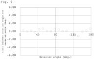
- Fig. 9 is shown the relationship between the rotation angle of the fine movement rotary stage after the correction of the error due to the polarization characteristics of the above-described optical system and the error with the measured polarization angle.
- the measurement error due to the polarization characteristics of illumination light can be reduced, the polarization state information to be originally measured can be more accurately measured, and the accuracy of polarization angle measurement can be improved by the technique of correcting the error due to the polarization characteristics of the optical system at the time of performing the polarization measurement.
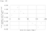
- a resin plate (observation target 10) with a surface that had been hairline-processed so as reflected light exhibits polarization was placed on a fine movement rotary stage 6, and images were captured while the resin plate was rotated from 0 to 180° in 15° increments.
- a polarization angle was measured using (Equation 1) for the captured images.
- Fig. 10 are shown the rotation angle of the fine movement rotary stage 6 before the correction of the error due to the polarization characteristics of the optical system and the error with the measured polarization angle.
- a correction coefficient s was calculated pixel by pixel by the method described in the [Second mode of correction coefficient creation] described above, and a correction coefficient distribution was created.
- the calculated correction coefficient corresponding to the polarization direction and the pixel position of the imaging unit is multiplied by the luminance value of each pixel of the polarization image obtained by imaging the observation target 10, and a corrected polarization image was thereby created.
- the polarization angle was measured again using (Equation 1).
- Fig. 11 is shown the relationship between the rotation angle of the fine movement rotary stage after the correction of the error due to the polarization characteristics of the optical system and the error with the measured polarization angle.
- the measurement error due to the polarization characteristics of illumination light can be reduced, the polarization state information to be originally measured can be more accurately measured, and the accuracy of polarization angle measurement can be improved by the technique of correcting the error due to the polarization characteristics of the optical system at the time of performing the polarization measurement.
- a correction coefficient is created from the polarization characteristics of an optical system acquired in advance, and then by use of the correction coefficient, polarization images obtained by imaging an observation target are subjected to correction processing of the polarization characteristics by the optical system. Therefore, it becomes possible to acquire a polarization image representing only the polarization characteristics of the observation target, and it becomes possible to evaluate the polarization characteristics of the observation target with high accuracy. Therefore, the present invention is particularly suitable for use in a device that performs, for example, highly accurate recognition of fiber orientation.
Landscapes
- Physics & Mathematics (AREA)
- General Physics & Mathematics (AREA)
- Health & Medical Sciences (AREA)
- Life Sciences & Earth Sciences (AREA)
- Chemical & Material Sciences (AREA)
- Analytical Chemistry (AREA)
- Biochemistry (AREA)
- General Health & Medical Sciences (AREA)
- Immunology (AREA)
- Pathology (AREA)
- Spectroscopy & Molecular Physics (AREA)
- Investigating Or Analysing Materials By Optical Means (AREA)
Applications Claiming Priority (2)
| Application Number | Priority Date | Filing Date | Title |
|---|---|---|---|
| JP2022034965 | 2022-03-08 | ||
| PCT/JP2022/044844 WO2023171058A1 (ja) | 2022-03-08 | 2022-12-06 | 偏光評価装置 |
Publications (2)
| Publication Number | Publication Date |
|---|---|
| EP4492020A1 true EP4492020A1 (de) | 2025-01-15 |
| EP4492020A4 EP4492020A4 (de) | 2026-02-25 |
Family
ID=87936499
Family Applications (1)
| Application Number | Title | Priority Date | Filing Date |
|---|---|---|---|
| EP22931029.7A Pending EP4492020A4 (de) | 2022-03-08 | 2022-12-06 | Vorrichtung zur polarisationsbeurteilung |
Country Status (3)
| Country | Link |
|---|---|
| EP (1) | EP4492020A4 (de) |
| JP (1) | JPWO2023171058A1 (de) |
| WO (1) | WO2023171058A1 (de) |
Families Citing this family (2)
| Publication number | Priority date | Publication date | Assignee | Title |
|---|---|---|---|---|
| FR3128022B1 (fr) * | 2021-10-08 | 2023-10-06 | Tiama | Dispositif et procédé opto-informatique d’analyse en lumière traversante d’un récipient en verre à l’aide d’une caméra numérique polarimétrique |
| WO2025079431A1 (ja) * | 2023-10-13 | 2025-04-17 | ソニーグループ株式会社 | 画像処理装置 |
Family Cites Families (8)
| Publication number | Priority date | Publication date | Assignee | Title |
|---|---|---|---|---|
| JP4260683B2 (ja) * | 2004-05-25 | 2009-04-30 | 大日本スクリーン製造株式会社 | エリプソメータ、偏光状態取得方法および光強度取得方法 |
| DE102012220923B4 (de) * | 2012-11-15 | 2014-07-10 | Fraunhofer-Gesellschaft zur Förderung der angewandten Forschung e.V. | Messung einer faserrichtung eines kohlefaserwerkstoffes und herstellung eines objekts in kohlefaserverbundbauweise |
| WO2017099253A1 (ja) * | 2015-12-11 | 2017-06-15 | 株式会社ニコン | 偏光特性画像計測装置、偏光特性画像計測方法 |
| JP2018044865A (ja) | 2016-09-14 | 2018-03-22 | 国立大学法人宇都宮大学 | 光学機器のキャリブレーション法 |
| EP3580546A1 (de) * | 2017-02-08 | 2019-12-18 | Yissum Research Development Company of The Hebrew University of Jerusalem Ltd. | System und verfahren zur verwendung in der ellipsometrie mit hoher räumlicher auflösung |
| WO2019198287A1 (ja) * | 2018-04-09 | 2019-10-17 | ソニー株式会社 | 情報処理装置と情報処理方法とプログラムおよびキャリブレーション装置 |
| JP2020080366A (ja) | 2018-11-13 | 2020-05-28 | ソニーセミコンダクタソリューションズ株式会社 | 受光装置 |
| CN112417370B (zh) * | 2020-11-12 | 2024-04-30 | 南京航空航天大学 | 粗糙表面物质的穆勒琼斯矩阵估计及偏振噪声分析方法 |
-
2022
- 2022-12-06 JP JP2022575756A patent/JPWO2023171058A1/ja active Pending
- 2022-12-06 WO PCT/JP2022/044844 patent/WO2023171058A1/ja not_active Ceased
- 2022-12-06 EP EP22931029.7A patent/EP4492020A4/de active Pending
Also Published As
| Publication number | Publication date |
|---|---|
| EP4492020A4 (de) | 2026-02-25 |
| WO2023171058A1 (ja) | 2023-09-14 |
| JPWO2023171058A1 (de) | 2023-09-14 |
Similar Documents
| Publication | Publication Date | Title |
|---|---|---|
| EP4492020A1 (de) | Vorrichtung zur polarisationsbeurteilung | |
| KR20190096831A (ko) | 편광 측정 장치, 편광 측정 방법 및 광 배향 방법 | |
| US7092093B2 (en) | Polarization bearing detection type two-dimensional light reception timing detecting device and surface form measuring device using the same | |
| CN111443045B (zh) | 光谱成像分析系统及光谱成像分析方法 | |
| US20040156051A1 (en) | Method and apparatus for measuring birefringence | |
| CN102095387A (zh) | 基于偏振光分束成像的旋光角度场探测装置及其测量方法 | |
| KR20170039232A (ko) | 복굴절 측정장치 및 복굴절 측정방법 | |
| CN114136894B (zh) | 一种基于涡旋波片的偏振检测系统的误差校准方法及装置 | |
| JP6679366B2 (ja) | 光学装置および撮像装置 | |
| JP2010071878A (ja) | 感度調整方法、偏光計測方法、及び偏光計測装置 | |
| Huang et al. | Hybrid calibration method for Mueller matrix microscopy | |
| JP5446644B2 (ja) | 楕円偏光板の貼合角測定装置 | |
| TW200819706A (en) | Interferometer angle sensitivity calibration method | |
| CN103210294A (zh) | 光学特性测量装置及方法 | |
| JP2011075548A (ja) | 積分型光検出器を使用したフーリエ係数測定法 | |
| KR101373709B1 (ko) | 3차원 필름의 주축과 위상차의 측정장치 및 측정방법 | |
| JP2006023295A (ja) | 複屈折測定法及びそれを用いた複屈折測定装置 | |
| JP2018044865A (ja) | 光学機器のキャリブレーション法 | |
| CN112880987A (zh) | 光学元件的偏振性能检测方法及检测系统 | |
| CN105136295A (zh) | 一种aotf同一幅图中光谱不均匀的解决方法及装置 | |
| JP2000111472A (ja) | 複屈折測定装置及びフィルムの配向測定装置 | |
| CN113218877B (zh) | 一种穆勒矩阵检测装置的校准方法 | |
| JP2010139345A (ja) | 複屈折測定装置 | |
| JPH11142322A (ja) | 複屈折測定装置及び複屈折測定方法 | |
| CN120628294A (zh) | 基于液晶可变相位延迟器的可见光宽谱段偏振成像系统及成像方法 |
Legal Events
| Date | Code | Title | Description |
|---|---|---|---|
| STAA | Information on the status of an ep patent application or granted ep patent |
Free format text: STATUS: THE INTERNATIONAL PUBLICATION HAS BEEN MADE |
|
| PUAI | Public reference made under article 153(3) epc to a published international application that has entered the european phase |
Free format text: ORIGINAL CODE: 0009012 |
|
| STAA | Information on the status of an ep patent application or granted ep patent |
Free format text: STATUS: REQUEST FOR EXAMINATION WAS MADE |
|
| 17P | Request for examination filed |
Effective date: 20240625 |
|
| AK | Designated contracting states |
Kind code of ref document: A1 Designated state(s): AL AT BE BG CH CY CZ DE DK EE ES FI FR GB GR HR HU IE IS IT LI LT LU LV MC ME MK MT NL NO PL PT RO RS SE SI SK SM TR |
|
| DAV | Request for validation of the european patent (deleted) | ||
| DAX | Request for extension of the european patent (deleted) | ||
| A4 | Supplementary search report drawn up and despatched |
Effective date: 20260126 |
|
| RIC1 | Information provided on ipc code assigned before grant |
Ipc: G01J 4/04 20060101AFI20260120BHEP Ipc: G01N 21/21 20060101ALI20260120BHEP |