EP4491584A1 - Method and device of water and sewage treatment - Google Patents
Method and device of water and sewage treatment Download PDFInfo
- Publication number
- EP4491584A1 EP4491584A1 EP24188487.3A EP24188487A EP4491584A1 EP 4491584 A1 EP4491584 A1 EP 4491584A1 EP 24188487 A EP24188487 A EP 24188487A EP 4491584 A1 EP4491584 A1 EP 4491584A1
- Authority
- EP
- European Patent Office
- Prior art keywords
- water
- confusor
- cavitator
- flow
- circulation
- Prior art date
- Legal status (The legal status is an assumption and is not a legal conclusion. Google has not performed a legal analysis and makes no representation as to the accuracy of the status listed.)
- Withdrawn
Links
Images
Classifications
-
- C—CHEMISTRY; METALLURGY
- C02—TREATMENT OF WATER, WASTE WATER, SEWAGE, OR SLUDGE
- C02F—TREATMENT OF WATER, WASTE WATER, SEWAGE, OR SLUDGE
- C02F1/00—Treatment of water, waste water, or sewage
- C02F1/34—Treatment of water, waste water, or sewage with mechanical oscillations
-
- B—PERFORMING OPERATIONS; TRANSPORTING
- B01—PHYSICAL OR CHEMICAL PROCESSES OR APPARATUS IN GENERAL
- B01F—MIXING, e.g. DISSOLVING, EMULSIFYING OR DISPERSING
- B01F23/00—Mixing according to the phases to be mixed, e.g. dispersing or emulsifying
- B01F23/40—Mixing liquids with liquids; Emulsifying
- B01F23/43—Mixing liquids with liquids; Emulsifying using driven stirrers
-
- B—PERFORMING OPERATIONS; TRANSPORTING
- B01—PHYSICAL OR CHEMICAL PROCESSES OR APPARATUS IN GENERAL
- B01F—MIXING, e.g. DISSOLVING, EMULSIFYING OR DISPERSING
- B01F23/00—Mixing according to the phases to be mixed, e.g. dispersing or emulsifying
- B01F23/40—Mixing liquids with liquids; Emulsifying
- B01F23/45—Mixing liquids with liquids; Emulsifying using flow mixing
- B01F23/451—Mixing liquids with liquids; Emulsifying using flow mixing by injecting one liquid into another
-
- B—PERFORMING OPERATIONS; TRANSPORTING
- B01—PHYSICAL OR CHEMICAL PROCESSES OR APPARATUS IN GENERAL
- B01F—MIXING, e.g. DISSOLVING, EMULSIFYING OR DISPERSING
- B01F25/00—Flow mixers; Mixers for falling materials, e.g. solid particles
- B01F25/30—Injector mixers
- B01F25/31—Injector mixers in conduits or tubes through which the main component flows
- B01F25/313—Injector mixers in conduits or tubes through which the main component flows wherein additional components are introduced in the centre of the conduit
- B01F25/3131—Injector mixers in conduits or tubes through which the main component flows wherein additional components are introduced in the centre of the conduit with additional mixing means other than injector mixers, e.g. screens, baffles or rotating elements
-
- B—PERFORMING OPERATIONS; TRANSPORTING
- B01—PHYSICAL OR CHEMICAL PROCESSES OR APPARATUS IN GENERAL
- B01F—MIXING, e.g. DISSOLVING, EMULSIFYING OR DISPERSING
- B01F25/00—Flow mixers; Mixers for falling materials, e.g. solid particles
- B01F25/40—Static mixers
- B01F25/42—Static mixers in which the mixing is affected by moving the components jointly in changing directions, e.g. in tubes provided with baffles or obstructions
- B01F25/43—Mixing tubes, e.g. wherein the material is moved in a radial or partly reversed direction
- B01F25/433—Mixing tubes wherein the shape of the tube influences the mixing, e.g. mixing tubes with varying cross-section or provided with inwardly extending profiles
- B01F25/4335—Mixers with a converging-diverging cross-section
-
- B—PERFORMING OPERATIONS; TRANSPORTING
- B01—PHYSICAL OR CHEMICAL PROCESSES OR APPARATUS IN GENERAL
- B01F—MIXING, e.g. DISSOLVING, EMULSIFYING OR DISPERSING
- B01F25/00—Flow mixers; Mixers for falling materials, e.g. solid particles
- B01F25/50—Circulation mixers, e.g. wherein at least part of the mixture is discharged from and reintroduced into a receptacle
- B01F25/51—Circulation mixers, e.g. wherein at least part of the mixture is discharged from and reintroduced into a receptacle in which the mixture is circulated through a set of tubes, e.g. with gradual introduction of a component into the circulating flow
-
- B—PERFORMING OPERATIONS; TRANSPORTING
- B01—PHYSICAL OR CHEMICAL PROCESSES OR APPARATUS IN GENERAL
- B01F—MIXING, e.g. DISSOLVING, EMULSIFYING OR DISPERSING
- B01F27/00—Mixers with rotary stirring devices in fixed receptacles; Kneaders
- B01F27/50—Pipe mixers, i.e. mixers wherein the materials to be mixed flow continuously through pipes, e.g. column mixers
-
- B—PERFORMING OPERATIONS; TRANSPORTING
- B01—PHYSICAL OR CHEMICAL PROCESSES OR APPARATUS IN GENERAL
- B01F—MIXING, e.g. DISSOLVING, EMULSIFYING OR DISPERSING
- B01F27/00—Mixers with rotary stirring devices in fixed receptacles; Kneaders
- B01F27/55—Mixers with rotary stirring devices in fixed receptacles; Kneaders with stirrers driven by the moving material
-
- C—CHEMISTRY; METALLURGY
- C02—TREATMENT OF WATER, WASTE WATER, SEWAGE, OR SLUDGE
- C02F—TREATMENT OF WATER, WASTE WATER, SEWAGE, OR SLUDGE
- C02F2201/00—Apparatus for treatment of water, waste water or sewage
- C02F2201/002—Construction details of the apparatus
- C02F2201/003—Coaxial constructions, e.g. a cartridge located coaxially within another
-
- C—CHEMISTRY; METALLURGY
- C02—TREATMENT OF WATER, WASTE WATER, SEWAGE, OR SLUDGE
- C02F—TREATMENT OF WATER, WASTE WATER, SEWAGE, OR SLUDGE
- C02F2301/00—General aspects of water treatment
- C02F2301/02—Fluid flow conditions
- C02F2301/024—Turbulent
-
- C—CHEMISTRY; METALLURGY
- C02—TREATMENT OF WATER, WASTE WATER, SEWAGE, OR SLUDGE
- C02F—TREATMENT OF WATER, WASTE WATER, SEWAGE, OR SLUDGE
- C02F2301/00—General aspects of water treatment
- C02F2301/06—Pressure conditions
- C02F2301/066—Overpressure, high pressure
-
- C—CHEMISTRY; METALLURGY
- C02—TREATMENT OF WATER, WASTE WATER, SEWAGE, OR SLUDGE
- C02F—TREATMENT OF WATER, WASTE WATER, SEWAGE, OR SLUDGE
- C02F2301/00—General aspects of water treatment
- C02F2301/08—Multistage treatments, e.g. repetition of the same process step under different conditions
-
- C—CHEMISTRY; METALLURGY
- C02—TREATMENT OF WATER, WASTE WATER, SEWAGE, OR SLUDGE
- C02F—TREATMENT OF WATER, WASTE WATER, SEWAGE, OR SLUDGE
- C02F2303/00—Specific treatment goals
- C02F2303/26—Reducing the size of particles, liquid droplets or bubbles, e.g. by crushing, grinding, spraying, creation of microbubbles or nanobubbles
-
- C—CHEMISTRY; METALLURGY
- C02—TREATMENT OF WATER, WASTE WATER, SEWAGE, OR SLUDGE
- C02F—TREATMENT OF WATER, WASTE WATER, SEWAGE, OR SLUDGE
- C02F2305/00—Use of specific compounds during water treatment
- C02F2305/02—Specific form of oxidant
- C02F2305/023—Reactive oxygen species, singlet oxygen, OH radical
Definitions
- the subject of the invention is a method for purifying sewage and water, for example river and mine water, using chemical solutions and hydrodynamic cavitation, where intensive mixing of various components, liquid and gaseous phases is necessary.
- the invention also relates to a device implementing this method, including a hydrodynamic device.
- a hydrodynamic cavitation reactor for mixing and dispersing gas-liquid systems is known from the Soviet application description SU1125041A1 .
- the reactor contains a flow chamber with a cavitator installed inside and a branch for introducing the reacting component.
- the cavitator is made in the form of two concentric truncated cones facing each other with large bases with radial blades between them, the inner part of which is made of a central and radial channel, while the smaller base of the outer cone is placed at the level of the large base of the inner cone.
- the radial blades are mounted at the level of the large base of the outer cone.
- the hydrodynamic cavitation reactor also includes a confusor, a diffuser and a manifold for supplying the base substance.
- the purpose of the invention is to intensify the chemical treatment process of river water, sewage and mine water, to reduce energy costs and the consumption of chemical reagents in the treatment process.
- the essence of the invention is a water purification device containing a hydrodynamic cavitator.
- the device is characterized by the fact that it contains:
- the device includes many chemical reagent inlet pipes ending with conical cavitators inside the confusor and, respectively, many flow chambers located behind the confusors.
- the device contains three stages of cavitation implemented by three cavitators, where the flow limitation d/D, i.e. the ratio of the diameter d of the chemical reagent pipes to the diameter D of the flow chambers, is 0.55 in the first stage, 0.45 in the second stage, 0.35 in third degree.
- the flow limitation d/D i.e. the ratio of the diameter d of the chemical reagent pipes to the diameter D of the flow chambers
- the circuit of the circulating pipeline of the device includes:
- the device includes many solenoid valves on the water supply, in the purified water circuit and on the purified water outlet.
- the essence of the invention is also a method of water purification using a hydrodynamic cavitator, which is characterized by the following steps:
- purification is carried out in many cycles, where the water purified in the first cycle is re-circulated to carry out stages b) and c).
- the water purified after step c) is subjected to spin cavitation carried out in the spin cavitation tank (12).
- the invention during cavitation treatment of sewage and river water, it is possible to reduce the level of impurities and pollutants without blowing or bubbling air and oxidizing agents, but only by changing the structure of water molecules and the occurrence of oxidizing radicals. Thanks to this, additional flotation can be eliminated or its duration can be significantly shortened.
- the ionization of the aqueous solution and the structural change of radicals in the water change the purification process, both in terms of purification steps and chemical consumption.
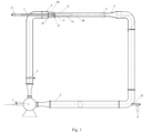
- the device in the most general version, shown in Fig. 1 .
- the device includes a circulation pump 1, a circulation pipeline 2 with a control valve 3, a reagent inlet pipe 7 with a valve 11, a confusor 4, a rotor cavitator 8, conical cavitator 6, flow chamber 5, diffuser 9 and branch pipe 10.
- Rotor cavitator 8 has the form of a super cavitator rotor rotating freely under the influence of the main liquid flow and is mounted on the inlet pipe 7 inside the confusor 4 and in front of the conical cavitator 6.
- Conical cavitator 6 it has the form of a cone with an opening angle of 90 °and is located inside the flow chamber 5 at its inlet.
- the diffuser 9 is located behind the flow chamber 5.
- the branch pipe 10 with a valve is used to collect purified water from the circulation pipeline 2.
- the volume and number of cavitation bubbles in the tail part of the L cavity determine the maximum cumulative effect of their collapse, and thus ensure optimal contact of chemical reagents with the water flow to be treated.
- Partial ionization of the processed liquid stream is also important, which allows for disinfection of the stream without the use of additional water treatment steps, such as the use of ultraviolet light, electric discharges or treatment with preparations containing chlorine.
- the device works as follows.
- Water or sewage intended for cleaning through the pipe by the circulation pump 1 fills the circulation circuit 2.
- the water is directed through the pipeline to the confusor 4.
- the chemical reagent is fed to the pipe 7, which ends with a conical cavitator 6.
- the flow of the chemical reagent is regulated by the valve 11.
- the flow of the liquid in circulation circuit is regulated by valve 3.
- a cavitation cavity of length L is created in the flow chamber 5, the pressure of which corresponds to the saturated vapor pressure of the liquid flowing around the cavitator 6.
- the working fluid i.e. the water subjected to purification
- a vacuum is created in the cavity, i.e. the pressure in the cavity corresponds to the saturated vapor pressure of the liquid at a temperature of 20 °C. In this way, the chemical reagent for water purification is intensively thrown into the cavity through pipe 7.
- the flow rate of the chemical reagent can be adjusted using valve 11 or valve 3 by changing the circulation flow rate.
- the rotor cavitator 8 is also flowed by the stream of working fluid. Then cavitation bubbles are partially formed on its blades, which then enter the flow chamber 5.
- the rotor cavitator 8 on the one hand, has the function of increasing the number of cavitation bubbles, and on the other hand, it contributes to the increase in pressure in front of the conical cavitator 6 in order to realize a stable developed cavitation mode behind the cavitator 6. This allows the energy of the main flow of the circulation pump 1 to be used to increase the pressure before the conical cavitator 6, and also increases the volume of cavitation bubbles in the diffuser zone 9 and increases the cumulative effect of these bubbles and the effectiveness of chemical reactions in water purification.
- the resulting mixture of chemical reagent and water enters the rear part of the cavitation cavity L in flow chamber 5, where, as a result of intense turbulent mixing of cavitation bubbles with the reagent, a chemical reaction of water purification takes place.
- a diffuser 9 is installed at the outlet of the flow chamber 5, in which, by changing the flow pressure, an enhanced chemical reaction of the interaction of water and the chemical reagent takes place. This intensification occurs as a result of the increase in the cumulative effect of the collapse of cavitation bubbles in the high pressure zone.
- water molecules split into radicals and the oxidation processes of organic substances in purified water intensify.
- H and OH radicals Dissociation of water molecules and dissolved organic and inorganic substances occurs.
- Water molecules are divided into H and OH radicals, which accumulate inside the bubble.
- high pressure fields of 10 2 to 10 3 MPa are created, the temperature increases, cumulative structures and shock waves appear. This leads to intense turbulent mixing and initiation of chemical reactions.
- H and OH radicals and their recombination products H 2 and H 2 O 2 pass into the purified liquid and enter into an oxidation reaction.
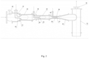
- FIG. 2 An example of a water purification device containing multiple cavitation modules is shown in Fig. 2 and Fig. 3 .
- Fig. 2 shows a three-stage cavitation module, where an example flow limitation d/D is 0.55 in the first stage, 0.45 in the second stage, 0.35 in the third stage.
- the device includes a valve 3 for regulating the flow of the liquid to be purified, three conical cavitators 6 with confusors 4, three flow chambers 5, tubes 7 supplying chemical reagents to the cavitators 6, a diffuser 9 located at the end of the cavitation stages and a swirl cavitation tank 12 with a vapor outlet chemical 35.
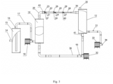
- Fig. 3 shows a diagram of the entire water and sewage treatment device in an exemplary embodiment including three stages of cavitation.
- the water and sewage treatment device includes a tank - settling tank 15, to which water to be purified is supplied through the inlet pipe 14.
- the tank 15 has an outlet, behind which there is a solenoid valve 16 on the pipeline 17.
- a filling pump 18 is installed on the pipeline 17.
- the pipeline is connected to the tank 19 for the purified water circulation.
- a pipe 20 of the purified water circuit is led out of the tank 19, ending with a confusor 37.
- a gate valve 42 In front of the confusor 37, a rotor cavitator 8 is installed.
- the rotor cavitator 8 is located in front of the first conical cavitator 21 on the circumference of the tube 23.
- the confusor 37 there is the first working flow chamber 22.
- the first supply tube 23 is led to the first working flow chamber 22 chemical reagent terminated with a conical cavitator 21.
- a cavitation cavity is created behind the conical cavitator 21.
- another second confusor 39 is placed, through which a second tube 26 supplying the chemical reagent is introduced into the second working flow chamber 25, ending with a second conical cavitator 24.
- the second conical cavitator 24 creates a cavitation cavity, to the beginning of which a chemical reagent is introduced.
- Behind the diffuser 30 is a swirl cavitation tank 12, which includes an outlet 35 for removing gaseous reaction products of water and chemical reagents.
- the tank 12 also includes a purified water outlet with a solenoid valve 31 .
- the tank 12 contains a third outlet with a solenoid valve 41 in the purified water circuit.
- a circulation pump 32 is installed in the pipeline 36 of the purified water circuit.
- the pipeline 36 is led to the tank 19 of the purified water circuit.
- the device works as follows. Contaminated water enters the settling tank 15 through the inlet pipe 14. After filling the settling tank 15, the solenoid valve 16 opens and the filling pump 18, located in the pipeline 17, pumps the purified water into the purified water tank 19. Then, the solenoid valve 16 closes and the water begins to circulate in the water treatment circuit using the pump 30.
- the purified water flows through the pipe 20 to the diffuser 27, where the first cavitator 31 with an additional rotor cavitator 8 is placed.
- the first cavitation cavity is created in the first working flow chamber 22 .
- the first tube 23 supplying the chemical reagent is led to the cavitation cavity.
- the first chemical reagent for water purification is mixed in the first cavitation cavity.
- each cavitation cavity may be supplied with the same or different chemical reagents for water purification depending on the type of contamination.
- the water flows into the diffuser 30, where the cavitation bubbles collapse intensively.
- the confusor 30 water is poured into the vortex cavitation tank 12. In the tank 12, the water flow is braked, which creates a vortex. This helps remove the gases produced in the reaction.
- the tank 12 has an outlet 35 for removing gaseous reaction products of purified water and reagents. If repeated or additional purification is necessary, the water from the tank 12 is recirculated through the open solenoid valve 13 using the circulation pump 32 through the water treatment circuit pipeline 36 to the water treatment circuit tank 19 and the process is repeated. After achieving the desired purification quality, the solenoid valve 13 is closed and the solenoid valve 31 is opened to drain the purified water. Water is pumped out of the circuit by means of the pump 33 through the nozzle 34 of the outlet pipe. Simultaneously or subsequently, the solenoid valve 16 is opened and another portion of water to be cleaned is taken from the settling tank 15 to the tank 19.
- Treatment of the treated water was carried out for 5 minutes in both examples.
- the reduction in pollution levels in the first case was 20%, in the second by 30%.
- the rotor is placed in a tight container with a capacity of up to 8 m 3 at 1 m from the liquid surface.
- the impeller diameter is 0.2 m.
- the initial level of chemical oxygen demand (COD) is 1060 at a temperature of 20 °C.
- Specific energy consumption is defined as the power used for mixing, related to powering the blades of the system. It was for:
- Table 3 Parameters Cavitation type rotary aerator Device according to the invention COD reduction % 7 10 9 30 Specific electricity consumption kW/h m 3 0.039 0.0796 0.045 0.1 Processing time (min) 5 5 rpm_ _ 1500 3000 1500 3000
- the device is used in all industries requiring water purification.
- the device is also used in broadly understood water and municipal management.
- circulation pump 29. a third tube supplying the chemical reagent 2.
- circulation circuit 3. valve 30. a diffuser increasing the effect of cavitation bubble collapse 4.
- confusor 5. flow chamber 31. solenoid valve for draining purified water 6. conical cavitator 7.
- circulation pump for water treatment circuit 8. rotor cavitator 9. diffuser 33. pump for pumping out purified water 10.
- branch pipe 11. chemical reagent supply valve 34. outlet pipe nozzle 12. vortex cavitation tank 35. outlet of the swirl cavitation tank 13.
- electrovalve 36. water treatment circuit pipeline 14. inlet pipe with cleaning water 37.
- electrovalve 40. third confusor 17. pipeline 41.
- solenoid valve in the purified water circuit 18. filling pump 19. water purification circuit tank 42. gate valve to regulate fluid flow 20. water purification circuit pipe 21. the first conical cavitator L - length of the cavitation cavity 22. first working flow chamber d - diameter of the conical cavitator inpart. its end 23. the first tube supplying the chemical reagent D - diameter of the flow chamber 24. second conical cavitator Pin- Pressure before cavitator (Pa) 25. second working flow chamber P ⁇ - pressure in the valve (Pa) 26. a second tube supplying the chemical reagent d/D - flow reduction degree 27. third conical cavitator Vin - flow speed before the cavitator (m/s) 28. third working flow chamber p - density (r) ⁇ - cavitation number
Landscapes
- Chemical & Material Sciences (AREA)
- Chemical Kinetics & Catalysis (AREA)
- Engineering & Computer Science (AREA)
- Mechanical Engineering (AREA)
- Life Sciences & Earth Sciences (AREA)
- Hydrology & Water Resources (AREA)
- Environmental & Geological Engineering (AREA)
- Water Supply & Treatment (AREA)
- Organic Chemistry (AREA)
- Dispersion Chemistry (AREA)
- Physical Water Treatments (AREA)
- Removal Of Specific Substances (AREA)
Applications Claiming Priority (1)
| Application Number | Priority Date | Filing Date | Title |
|---|---|---|---|
| PL445572A PL445572A1 (pl) | 2023-07-13 | 2023-07-13 | Sposób oczyszczania wód i ścieków oraz urządzenie do jego realizacji |
Publications (1)
| Publication Number | Publication Date |
|---|---|
| EP4491584A1 true EP4491584A1 (en) | 2025-01-15 |
Family
ID=92538389
Family Applications (1)
| Application Number | Title | Priority Date | Filing Date |
|---|---|---|---|
| EP24188487.3A Withdrawn EP4491584A1 (en) | 2023-07-13 | 2024-07-12 | Method and device of water and sewage treatment |
Country Status (2)
| Country | Link |
|---|---|
| EP (1) | EP4491584A1 (pl) |
| PL (1) | PL445572A1 (pl) |
Citations (6)
| Publication number | Priority date | Publication date | Assignee | Title |
|---|---|---|---|---|
| SU1125041A1 (ru) | 1983-06-03 | 1984-11-23 | Киевский Ордена Ленина Политехнический Институт Им.50-Летия Великой Октябрьской Социалистической Революции | Гидродинамический кавитационный реактор |
| SU1191428A1 (ru) | 1984-04-25 | 1985-11-15 | Производственное Управление Пусконаладочных Работ "Вектор" | Аэратор |
| SU1468870A1 (ru) | 1987-05-26 | 1989-03-30 | Республиканское Управление Пусконаладочных Работ По Водоснабжению И Водоотведению "Авотс" | Кавитационный аэратор |
| WO1996009112A1 (de) * | 1994-09-21 | 1996-03-28 | Schüler, Rolf | Vorrichtung zur erzeugung flüssiger systeme, insbesondere von emulsionen, suspensionen od. dgl. in einem hydrodynamischen kavitationsfeld |
| US20030147303A1 (en) * | 2000-02-28 | 2003-08-07 | Rolf Schueler | Cavitation mixer |
| CN114940527A (zh) * | 2022-02-28 | 2022-08-26 | 成都理工大学 | 一种压力可调水力空化地下水循环井系统 |
Family Cites Families (3)
| Publication number | Priority date | Publication date | Assignee | Title |
|---|---|---|---|---|
| CN105438322A (zh) * | 2015-12-04 | 2016-03-30 | 重庆市永川区邦威机械制造有限公司 | 一种摩托车智能控制系统 |
| CN106186179A (zh) * | 2016-08-29 | 2016-12-07 | 江苏大学 | 一种基于水力空化的有机水污染降解系统 |
| KR20190126768A (ko) * | 2016-12-15 | 2019-11-12 | 마이클 스미스 | 유체 중에 캐비테이션을 생성하기 위한 시스템 및 방법 |
-
2023
- 2023-07-13 PL PL445572A patent/PL445572A1/pl unknown
-
2024
- 2024-07-12 EP EP24188487.3A patent/EP4491584A1/en not_active Withdrawn
Patent Citations (6)
| Publication number | Priority date | Publication date | Assignee | Title |
|---|---|---|---|---|
| SU1125041A1 (ru) | 1983-06-03 | 1984-11-23 | Киевский Ордена Ленина Политехнический Институт Им.50-Летия Великой Октябрьской Социалистической Революции | Гидродинамический кавитационный реактор |
| SU1191428A1 (ru) | 1984-04-25 | 1985-11-15 | Производственное Управление Пусконаладочных Работ "Вектор" | Аэратор |
| SU1468870A1 (ru) | 1987-05-26 | 1989-03-30 | Республиканское Управление Пусконаладочных Работ По Водоснабжению И Водоотведению "Авотс" | Кавитационный аэратор |
| WO1996009112A1 (de) * | 1994-09-21 | 1996-03-28 | Schüler, Rolf | Vorrichtung zur erzeugung flüssiger systeme, insbesondere von emulsionen, suspensionen od. dgl. in einem hydrodynamischen kavitationsfeld |
| US20030147303A1 (en) * | 2000-02-28 | 2003-08-07 | Rolf Schueler | Cavitation mixer |
| CN114940527A (zh) * | 2022-02-28 | 2022-08-26 | 成都理工大学 | 一种压力可调水力空化地下水循环井系统 |
Also Published As
| Publication number | Publication date |
|---|---|
| PL445572A1 (pl) | 2025-01-20 |
Similar Documents
| Publication | Publication Date | Title |
|---|---|---|
| CA2529020C (en) | Device and method for generating microbubbles in a liquid using hydrodynamic cavitation | |
| US4337152A (en) | Aeration apparatus and method | |
| CN101679083B (zh) | 净化液体排放物的方法和装置 | |
| US3650950A (en) | Material shearing mixer and aerator | |
| CN102910772A (zh) | 一种紫外光协同臭氧微纳米气泡的废水处理系统和方法 | |
| US6315893B1 (en) | Gas/liquid mixer with degasifier | |
| CN104876375A (zh) | 一种深度氧化水处理方法及装置 | |
| KR100674510B1 (ko) | 수처리 공정 및 장치 | |
| EP4491584A1 (en) | Method and device of water and sewage treatment | |
| KR100437971B1 (ko) | 유체 혼합기 및 이 혼합기가 구비된 수처리용 전해처리시스템 | |
| KR100882818B1 (ko) | 폭기조 | |
| KR100469317B1 (ko) | 오존을 이용한 오폐수 고도 처리시스템 | |
| KR100427594B1 (ko) | 미세기포를 이용하여 하폐수에서 용존성 고형물과 부유성고형물을 동시에 제거하는 폐수처리 장치 및 방법 | |
| KR102596611B1 (ko) | 기포를 이용한 분리막 세정 장치 및 이를 구비하는 mbr 공법 기반 하폐수 처리 설비 | |
| KR102656572B1 (ko) | 산소를 이용한 오폐수의 전처리 시스템 | |
| CN115215424A (zh) | 一种基于微气泡撞击流臭氧废水处理装置及系统 | |
| HU221784B1 (hu) | Szennyvíztisztító reaktor | |
| KR101206905B1 (ko) | 플라즈마 방전 반응 장치와 가압부상조를 이용한 수처리 시스템 | |
| KR102752860B1 (ko) | 여과 및 산화 기능을 갖는 폐수 처리 시스템 | |
| CN120247321B (zh) | 一种印染废水的催化氧化深度处理工艺及处理装置 | |
| JP7792119B2 (ja) | 浄化装置 | |
| KR100626180B1 (ko) | 생물학적 폐수처리를 위한 장치 및 그 방법 | |
| KR20200142963A (ko) | 기체 용해 장치 및 그를 포함하는 미세기포 발생장치 | |
| KR20180113477A (ko) | 순환구조를 가지는 유체혼합 토출장치 | |
| KR102047486B1 (ko) | 미세기포를 이용하는 질소제거 단일생물반응시스템 및 그 처리방법 |
Legal Events
| Date | Code | Title | Description |
|---|---|---|---|
| PUAI | Public reference made under article 153(3) epc to a published international application that has entered the european phase |
Free format text: ORIGINAL CODE: 0009012 |
|
| STAA | Information on the status of an ep patent application or granted ep patent |
Free format text: STATUS: THE APPLICATION HAS BEEN PUBLISHED |
|
| AK | Designated contracting states |
Kind code of ref document: A1 Designated state(s): AL AT BE BG CH CY CZ DE DK EE ES FI FR GB GR HR HU IE IS IT LI LT LU LV MC ME MK MT NL NO PL PT RO RS SE SI SK SM TR |
|
| STAA | Information on the status of an ep patent application or granted ep patent |
Free format text: STATUS: THE APPLICATION IS DEEMED TO BE WITHDRAWN |
|
| 18D | Application deemed to be withdrawn |
Effective date: 20250716 |