EP4489337A1 - Srs-sendeverfahren und -vorrichtung, srs-empfangsverfahren und -vorrichtung, vorrichtung, medium und produkt - Google Patents
Srs-sendeverfahren und -vorrichtung, srs-empfangsverfahren und -vorrichtung, vorrichtung, medium und produkt Download PDFInfo
- Publication number
- EP4489337A1 EP4489337A1 EP22929358.4A EP22929358A EP4489337A1 EP 4489337 A1 EP4489337 A1 EP 4489337A1 EP 22929358 A EP22929358 A EP 22929358A EP 4489337 A1 EP4489337 A1 EP 4489337A1
- Authority
- EP
- European Patent Office
- Prior art keywords
- antenna port
- port groups
- srs
- antenna
- ports
- Prior art date
- Legal status (The legal status is an assumption and is not a legal conclusion. Google has not performed a legal analysis and makes no representation as to the accuracy of the status listed.)
- Pending
Links
Images


Classifications
-
- H—ELECTRICITY
- H04—ELECTRIC COMMUNICATION TECHNIQUE
- H04L—TRANSMISSION OF DIGITAL INFORMATION, e.g. TELEGRAPHIC COMMUNICATION
- H04L5/00—Arrangements affording multiple use of the transmission path
- H04L5/003—Arrangements for allocating sub-channels of the transmission path
- H04L5/0048—Allocation of pilot signals, i.e. of signals known to the receiver
- H04L5/0051—Allocation of pilot signals, i.e. of signals known to the receiver of dedicated pilots, i.e. pilots destined for a single user or terminal
-
- H—ELECTRICITY
- H04—ELECTRIC COMMUNICATION TECHNIQUE
- H04B—TRANSMISSION
- H04B7/00—Radio transmission systems, i.e. using radiation field
- H04B7/02—Diversity systems; Multi-antenna system, i.e. transmission or reception using multiple antennas
- H04B7/04—Diversity systems; Multi-antenna system, i.e. transmission or reception using multiple antennas using two or more spaced independent antennas
- H04B7/0404—Diversity systems; Multi-antenna system, i.e. transmission or reception using multiple antennas using two or more spaced independent antennas the mobile station comprising multiple antennas, e.g. to provide uplink diversity
-
- H—ELECTRICITY
- H04—ELECTRIC COMMUNICATION TECHNIQUE
- H04B—TRANSMISSION
- H04B7/00—Radio transmission systems, i.e. using radiation field
- H04B7/02—Diversity systems; Multi-antenna system, i.e. transmission or reception using multiple antennas
- H04B7/04—Diversity systems; Multi-antenna system, i.e. transmission or reception using multiple antennas using two or more spaced independent antennas
- H04B7/06—Diversity systems; Multi-antenna system, i.e. transmission or reception using multiple antennas using two or more spaced independent antennas at the transmitting station
- H04B7/0686—Hybrid systems, i.e. switching and simultaneous transmission
- H04B7/0691—Hybrid systems, i.e. switching and simultaneous transmission using subgroups of transmit antennas
-
- H—ELECTRICITY
- H04—ELECTRIC COMMUNICATION TECHNIQUE
- H04L—TRANSMISSION OF DIGITAL INFORMATION, e.g. TELEGRAPHIC COMMUNICATION
- H04L27/00—Modulated-carrier systems
- H04L27/26—Systems using multi-frequency codes
- H04L27/2601—Multicarrier modulation systems
- H04L27/2602—Signal structure
- H04L27/2605—Symbol extensions, e.g. Zero Tail, Unique Word [UW]
-
- H—ELECTRICITY
- H04—ELECTRIC COMMUNICATION TECHNIQUE
- H04L—TRANSMISSION OF DIGITAL INFORMATION, e.g. TELEGRAPHIC COMMUNICATION
- H04L5/00—Arrangements affording multiple use of the transmission path
- H04L5/0001—Arrangements for dividing the transmission path
- H04L5/0014—Three-dimensional division
- H04L5/0023—Time-frequency-space
-
- H—ELECTRICITY
- H04—ELECTRIC COMMUNICATION TECHNIQUE
- H04W—WIRELESS COMMUNICATION NETWORKS
- H04W72/00—Local resource management
- H04W72/04—Wireless resource allocation
- H04W72/044—Wireless resource allocation based on the type of the allocated resource
- H04W72/0453—Resources in frequency domain, e.g. a carrier in FDMA
-
- H—ELECTRICITY
- H04—ELECTRIC COMMUNICATION TECHNIQUE
- H04W—WIRELESS COMMUNICATION NETWORKS
- H04W72/00—Local resource management
- H04W72/20—Control channels or signalling for resource management
- H04W72/21—Control channels or signalling for resource management in the uplink direction of a wireless link, i.e. towards the network
-
- H—ELECTRICITY
- H04—ELECTRIC COMMUNICATION TECHNIQUE
- H04W—WIRELESS COMMUNICATION NETWORKS
- H04W72/00—Local resource management
- H04W72/20—Control channels or signalling for resource management
- H04W72/23—Control channels or signalling for resource management in the downlink direction of a wireless link, i.e. towards a terminal
Definitions
- the disclosure relates to a communication field, in particular to a method for sending a sounding reference signal (SRS), a method for receiving an SRS, an apparatus, a device, a medium and a product.
- SRS sounding reference signal
- an uplink sounding reference signal (SRS) is used to measure and estimate a channel quality of an uplink channel.
- SRS uplink sounding reference signal
- a plurality of antenna ports may be configured for a user equipment (UE), and the UE supports sending the SRS at up to 4 antenna ports.
- UE user equipment
- Embodiments of the disclosure provide a method for sending a sounding reference signal (SRS), a method for receiving an SRS, an apparatus, a device, a medium and a product.
- SRS sounding reference signal
- the technical solutions are provided as follows.
- a method for sending an SRS, performed by a terminal includes:
- a method for receiving an SRS, performed by a network device includes:
- an apparatus for sending an SRS includes:
- an apparatus for receiving an SRS includes:
- a terminal includes:
- a network device includes:
- a computer-readable storage medium having at least one instruction, at least one program segment, a code set or an instruction set stored thereon is provided.
- the at least one instruction, the at least one program segment, the code set or the instruction set is loaded and executed by a processor, the method for sending an SRS as described in the above aspects or the method for receiving an SRS is implemented.
- a computer program product including computer instructions is provided.
- the computer instructions are stored in a computer-readable storage medium and can be read by a processor of a computer device from the computer-readable storage medium.
- the computer instructions are executed by the processor, the computer is caused to implement the method for sending an SRS as described in the above aspects or the method for receiving an SRS.
- the 8 antenna ports in the SRS resource are divided into at least two antenna port groups.
- the terminal After receiving the configuration information of the SRS resource, the terminal maps the SRSs corresponding to the at least two antenna port groups on the physical resources corresponding to different transmission combs and sends the SRSs corresponding to the at least two antenna port groups simultaneously.
- This method is used to support implementation of related functions in a situation where the terminal uses the 8 sending antenna ports, for example, used to support codebook-based channel quality sounding in a situation where the terminal uses the 8 sending antenna ports, or used to support non-codebook-based channel quality sounding in a situation where the terminal uses the 8 sending antenna ports, or used to support channel quality sounding during antenna switching in a situation where the terminal uses the 8 sending antenna ports.
- FIG. 1 is a block diagram of a communication system according to an exemplary embodiment.
- the communication system includes: an access network 12 and a user equipment (UE) 14.
- UE user equipment
- the access network 12 includes several network devices 120.
- the network device 120 may be a base station deployed in the access network to provide wireless communication functions for the UE 14.
- the base station may include various forms of macro base stations, micro base stations, relay stations, access points, etc.
- the name of device with the functions of the base station may be different.
- LTE long term evolution
- eNB eNodeB
- gNodeB gNodeB
- base station may be described differently.
- the above-described devices that provide wireless communication functions for the UE 14 are collectively referred to as a network device.
- the UE 14 may include a variety of handheld devices with wireless communication functions, vehicle-mounted devices, wearable devices, computing devices, or other processing devices connected to a wireless modem, and various forms of UEs, mobile stations (MSs), terminal devices, etc. For ease of description, the devices mentioned above are collectively referred to as a UE.
- the network device 120 and the UE 14 may communicate with each other via some sort of air interface technology, such as a Uu interface.
- Uplink communication refers to sending signals to the network device 120
- downlink communication refers to sending signals to the UE 14.
- GSM Global System of Mobile Communication
- CDMA Code Division Multiple Access
- WCDMA Wideband Code Division Multiple Access
- GPRS General Packet Radio Service
- LTE Long Term Evolution
- FDD Frequency Division Duplex
- TDD Time Division Duplex
- LTE-A Advanced long Term Evolution
- NR Universal Mobile Telecommunication System
- UMTS Universal Mobile Telecommunication System
- WiMAX Worldwide Interoperability for Microwave Access
- WLAN Wireless Local Area Networks
- WiFi Wireless Fidelity
- D2D Device to Device
- M2M Machine to Machine
- MTC Machine Type Communication
- V2V Vehicle to Vehicle
- V2X Vehicle to Everything
- FIG. 2 is a flowchart illustrating a method for sending a sounding reference signal (SRS) according to an exemplary embodiment. The method is applied to the terminal in the communication system shown in FIG. 1 . The method includes following steps.
- SRS sounding reference signal
- the SRS resource includes 8 antenna ports.
- the terminal receives the configuration information of the SRS resource sent by the network device.
- the configuration information is used to configure one SRS resource for the terminal.
- SRSs corresponding to at least two antenna port groups are mapped to physical resources corresponding to different transmission combs, and the SRSs corresponding to the at least two antenna port group are sent simultaneously, in which the at least two antenna port groups are obtained based on grouping the 8 antenna ports.
- the terminal maps one SRS resource on the same physical resource (PR) when measuring a channel quality of an uplink channel.
- PR refers to consecutive carrier resources in a frequency domain
- one physical resource block (PRB) corresponds to 12 continuous carriers in the frequency domain and one slot in a time domain.
- the uplink channel includes at least one of: a Physical Uplink Control CHannel (PUCCH) and a Physical Uplink Shared CHannel (PUSCH).
- the terminal may map one SRS resource on the PR of the PUCCH and/or the PUSCH.
- the terminal maps one SRS resource on the same PR according to the configuration information.
- the above configuration information includes at least one of following parameters:
- the transmission comb parameter is used to indicate a comb structure of the SRS resource in the frequency domain, i.e., the SRS resource is not mapped on consecutive subcarriers.
- the frequency-domain offset parameter is an offset of subcarriers occupied by the 1st RE resource in one SRS resource, and the frequency-domain offset parameter is a non-negative integer less than the transmission comb parameter.
- the SRS configuration bandwidth is a frequency bandwidth occupied by the SRS resource.
- the cyclic shift parameter is a number of bits by which the sequence is cyclically shifted.
- the antenna port is a logical transmitting channel defined by a reference signal, and the antenna port is mapped to a physical antenna for sending of signals.
- the time-domain location of the transmission comb is a symbol occupied by the transmission comb in the slot.
- the above configuration information may also include: a length of a ZC sequence, which is a numerical length of the ZC sequence.
- the terminal generates 8 SRS sequences based on at least one ZC sequence, and carries the SRSs of the 8 antenna ports through the 8 SRS sequences.
- each antenna port group corresponds to one transmission comb.
- the terminal maps the SRSs corresponding to the at least two antenna port groups on PRs corresponding to at least two transmission combs, and sends the SRSs corresponding to the at least two antenna port groups simultaneously.
- the at least two antenna port groups may be antenna port groups mapped to the same antenna panel or different antenna panels. That is, the at least two antenna ports are antenna port groups mapped to M antenna panels, M being a positive integer less than or equal to 8. For example, a first antenna port group of the at least two antenna port groups is mapped to a first antenna panel, and a second antenna port group of the at least two antenna port groups is mapped to a second antenna panel.
- OFDM orthogonal frequency-division multiplexing
- a function of the SRS resource includes one of:
- the terminal may perform codebook-based channel quality sounding, channel quality sounding during antenna switching, or non-codebook-based channel quality sounding.
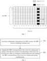
- a value range of the transmission comb parameter K TC is ⁇ 2,4,8,12 ⁇ .
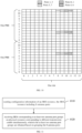
- K TC 2 for example, under a condition that the transmission comb parameter is equal to 2, the terminal maps two transmission combs, i.e., a first transmission comb 301 and a second transmission comb 302, on one PRB.
- a frequency-domain offset parameter of the first transmission comb 301 is 0, and a frequency-domain offset parameter of the second transmission comb 302 is 1.
- Adjacent subcarriers in each transmission comb are spaced by 1 subcarrier, and subcarriers occupied by the first transmission comb 301 include a subcarrier 0, a subcarrier 2, a subcarrier 4, a subcarrier 6, a subcarrier 8 and a subcarrier 10, and subcarriers occupied by the second transmission comb 302 include a subcarrier 1, a subcarrier 3, a subcarrier 5, a subcarrier 7, a subcarrier 9 and a subcarrier 11.
- the first transmission comb 301 and the second transmission comb 302 are located on 10 symbols within one slot.
- each transmission comb resource of the two transmission combs in FIG. 3 may occupy one OFDM symbol.
- a maximum value of the cyclic shift parameter of the transmission combs corresponding to the at least two antenna port groups is n SRS cs , max
- a value range of the cyclic shift parameter n SRS cs configured for the 8 antenna ports is n SRS cs ⁇ 0 , 1,2 , ... , n SRS cs , max ⁇ 1 .
- a maximum value of a number of the cyclic shift parameters supported by the transmission comb parameter is 8, and the value range of n SRS cs is n SRS cs ⁇ 0 , 1,2 , ... , n SRS cs ,max ⁇ 1 , then the terminal generates the SRS resource by using 8 cyclic shift parameters.
- a maximum value of a number of the cyclic shift parameters supported by the transmission comb parameter is 12, and the value range of n SRS cs is n SRS cs ⁇ 0,1 , ... , n SRS cs ,max ⁇ 1 , then the terminal generates the SRS resource by using some of the 12 cyclic shift parameters, e.g., generates the SRS resource by actually using 8 of the 12 cyclic shift parameters.
- the above configuration information includes one cyclic shift parameter corresponding to the at least two antenna port groups.
- the terminal calculates the cyclic shift parameter corresponding to all antenna ports in the at least two antenna port groups based on the configured cyclic shift parameter.
- the above configuration information includes one cyclic shift parameter corresponding to each antenna port of the at least two antenna port groups.
- the terminal After receiving the configuration information, for each antenna port group, the terminal calculates the cyclic shift parameter corresponding to all ports within the antenna port group by using the cyclic shift parameter configured for the antenna port group.
- n SRS cs ,i n SRS cs + n SRS cs ,max p i ⁇ 1000 N ap SRS mod n SRS cs ,max .
- one SRS resource can be mapped on one PRB, thus, a minimum bandwidth parameter corresponding to an SRS configuration bandwidth is greater than or equal to a bandwidth of 6 PRBs.
- the SRS configuration bandwidth is a multiple of the bandwidth of 6 PRBs.
- the minimum bandwidth parameter corresponding to the SRS configuration bandwidth is greater than or equal to a bandwidth of 8 PRBs.
- the SRS configuration bandwidth is a multiple of the bandwidth of 8 PRBs.
- the 8 antenna ports in the SRS resource are divided into at least two antenna port groups.
- the terminal maps the SRSs corresponding to the at least two antenna port groups on the PRs corresponding to different transmission combs and sends the SRSs corresponding to the at least two antenna port groups simultaneously.
- This method is used to support implementation of related functions in a situation where the terminal uses the 8 sending antenna ports, for example, used to support codebook-based channel quality sounding in a situation where the terminal uses the 8 sending antenna ports, or used to support non-codebook-based channel quality sounding in a situation where the terminal uses the 8 sending antenna ports, or used to support channel quality sounding during antenna switching in a situation where the terminal uses the 8 sending antenna ports.
- the at least two antenna port groups may be mapped to at least two transmission combs with different frequency-domain offset parameters of the transmission combs.
- step 220 may be realized by step 420 as follows.
- SRSs corresponding to at least two antenna port groups are mapped to PRs corresponding to at least two transmission combs in a frequency domain dimension, and the SRSs corresponding to the at least two antenna port groups are sent simultaneously.
- the antenna port groups have a one-to-one correspondence with the transmission combs.
- time-domain locations of the transmission combs corresponding to the at least two antenna port groups are identical.
- the first transmission comb 301 and the second transmission comb 302 in FIG. 3 are both located on a symbol 10 of a slot.
- the transmission comb parameters K TC of the transmission combs corresponding to the at least two antenna port groups are identical.
- the transmission comb parameter of each of the first transmission comb 301 and the second transmission comb 302 in FIG. 3 is 2.
- the frequency-domain offset parameters k TC of the transmission combs corresponding to the at least two antenna port groups are different, and a value of k TC is a non-negative integer less than K TC .
- a value of the transmission comb parameter is 8
- a value range of the frequency-domain offset parameters of the transmission combs corresponding to the at least two antenna port groups is ⁇ 0,1,2,3,4,5,6,7 ⁇ .
- some or all of the above frequency-domain offset parameters of the transmission combs are configured by the network device for the terminal.
- the terminal receives a first frequency-domain offset parameter of a transmission comb corresponding to a first antenna port group, the first antenna port group being one of the at least two antenna port groups, and calculates other frequency-domain offset parameters of transmission combs corresponding to other antenna port groups based on the first frequency-domain offset parameter, other antenna port groups being antenna port groups other than the first antenna port group in the at least two antenna port groups.
- the terminal receives frequency-domain offset parameters of transmission combs corresponding to the at least two antenna port groups.
- the network device configures a frequency-domain offset parameter k TC of one transmission comb for the terminal, and calculates frequency-domain offset parameters k TC p i of other transmission combs based on the frequency-domain offset parameter k TC .
- the network device configures a set of frequency-domain offset parameters corresponding to at least two transmission combs for the terminal.
- the terminal calculates other frequency-domain offset parameters based on an adjacent transmission comb principle, calculates other frequency-domain offset parameters based on a uniform distribution principle, calculates other frequency-domain offset parameters based on a maximum interval principle, or calculates other frequency-domain offset parameters based on other predefined principles.
- the above four principles of determining other frequency-domain offset parameters are described in the following.
- any two adjacent subcarriers are subcarriers corresponding to the first transmission comb 301 and the second transmission comb 302 respectively.
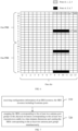
- the third transmission comb 501 and the fourth transmission comb 502 both occupy a symbol 12 and a symbol 13 of a slot. Adjacent subcarriers in each transmission comb are spaced by 3 subcarriers.
- the subcarriers occupied by the third transmission comb 501 include a subcarrier 1, a subcarrier 5 and a subcarrier 9, and the subcarriers occupied by the fourth transmission comb 502 include a subcarrier 3, a subcarrier 7, and a subcarrier 11.
- adjacent subcarriers corresponding to two transmission combs is spaced by 1 subcarrier, that is, the two transmission combs conform to the uniform distribution principle.
- a difference in the frequency-domain offset parameters between consecutive transmission combs is a maximum value.
- K TC 4
- the first frequency-domain offset parameter is 0, and other frequency-domain offset parameters are 3, and thus at least two transmission combs meet the maximum interval principle.
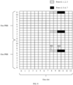
- the fifth transmission comb 601 and the sixth transmission comb 602 occupy 4 consecutive symbols 8-11 of the slot. Adjacent subcarriers in each transmission comb are spaced by 7 subcarriers.
- the subcarriers occupied by the fifth transmission comb 601 include a subcarrier 0 and a subcarrier 8 of the 1st PRB, and a subcarrier 4 of the 2nd PRB
- the subcarriers occupied by the sixth transmission comb 602 include a subcarrier 7 of the 1st PRB, and a subcarrier 3 and a subcarrier 11 of the 2nd PRB.
- the 6 subcarriers corresponding to the two transmission combs two corresponding subcarriers are separated by 6 subcarriers, that is, the two transmission combs meet the maximum interval principle.
- the method for sending an SRS provided in an embodiment supports a plurality of antenna port groups to send the SRS on a plurality of transmission combs in different frequency domain dimensions.
- the at least two antenna port groups are mapped to at least two transmission combs with the identical frequency-domain offset parameter of the transmission combs.
- step 220 can be implemented by step 720.
- SRSs corresponding to at least two antenna port groups are mapped to PRs corresponding to at least two transmission combs in a time domain dimension, and the SRSs corresponding to the at least two antenna port groups are sent simultaneously.
- the antenna port groups have a one-to-one correspondence with the transmission combs.
- time domain locations of the transmission combs corresponding to the at least two antenna port groups are different and adjacent.
- transmission comb parameters K TC of the transmission combs corresponding to the at least two antenna port groups are identical.
- frequency-domain offset parameters k TC of the transmission combs corresponding to the at least two antenna port groups are identical, and a value of k TC is a non-negative integer less than K TC .
- a value range of the frequency-domain offset parameter of the transmission combs corresponding to the at least two antenna port groups is ⁇ 0,1,2,3,4,5,6,7 ⁇ .
- a seventh transmission comb 801 and an eighth transmission comb 802 are configured in the SRS resource.
- the transmission comb parameters of the seventh transmission comb 801 and the eighth transmission comb 802 are both 8, and the frequency-domain offset parameters of the seventh transmission comb 801 and the eighth transmission comb 802 are both 7.
- the seventh transmission comb 801 and the eighth transmission comb 802 are located on the same subcarrier, including: a subcarrier 7 on the first PRB, and a subcarrier 3 and a subcarrier 11 on the second PRB.
- the seventh transmission comb 801 and the eighth transmission comb 802 are located at different time-domain locations, the seventh transmission comb 801 is located on symbols 8 and 9 of a slot, and the eighth transmission comb 802 is located on symbols 10 and 11 of the slot.
- the time-domain locations of the seventh transmission comb 801 and the eighth transmission comb 802 are adjacent.
- the time-domain locations of at least two transmission combs may be located in the same slot or different slots.
- the seventh transmission comb 801 and the eighth transmission comb 802 in FIG. 8 are located in the same slot.
- the network device configures the frequency-domain offset parameter of the transmission combs corresponding to the at least two antenna port groups for the terminal.
- the terminal receives one frequency-domain offset parameter of the transmission combs corresponding to the at least two antenna port groups. That is, the network device configures one frequency -domain offset parameter k TC of the transmission comb for the terminal.
- the method for sending an SRS provided in an embodiment supports a plurality of antenna port groups to send the SRS on a plurality of transmission combs in different time domain dimensions.
- At least two antenna port groups are obtained by dividing the 8 antenna ports into different groups sequentially according to port numbers. As illustrated in FIG. 3 , one antenna port group includes port 0, port 1, port 2 and port 3, and the other antenna port group includes port 4, port 5, port 6 and port 7.
- At least two antenna port groups are obtained by dividing the 8 antenna ports into a group containing even-numbered ports and a group containing odd-numbered ports. As illustrated in FIG. 5 , one antenna port group includes port 0, port 2, port 4 and port 6, and the other antenna port group includes port 1, port 3, port 5 and port 7.
- the at least two antenna port groups are obtained by dividing odd-numbered ports in the 8 antenna ports into at least two first antenna port groups sequentially and dividing even-numbered ports in the 8 antenna ports into at least two second antenna port groups sequentially.
- one first antenna port group includes port 1 and port 3
- the other first antenna port group includes port 5 and port 7
- one second antenna port group includes port 0 and port 2
- the other second antenna port group includes port 4 and port 6.
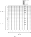
- the transmission comb parameter configured in the SRS resource is 12, and the frequency-domain offset parameters of the transmission comb include ⁇ 5, 7, 9, 11 ⁇ . Therefore, there are four transmission combs having the same transmission comb structure.
- ports with the port number being even among the eight antenna ports include: port 0, port 2, port 4 and port 6, and ports with the port number being odd among the eight antenna ports include: port 1, port 3, port 5 and port 7.
- a first antenna port group includes port 1 and port 3, and the other first antenna port group includes port 5 and port 7, and a second antenna port group includes port 0 and port 2, and the other second antenna port group includes port 4 and port 6.
- At least two antenna port groups are divided into groups according to predefined combinations in a protocol. For example, port 0, port 1, port 6 and port 7 predefined in the protocol are one antenna port group, and port 2, port 3, port 4 and port 5 predefined in the protocol are the other antenna port group.
- the method for sending an SRS provided in an embodiment supports a plurality of port combinations to send the SRS on a plurality of transmission combs.
- FIG. 11 is a flowchart illustrating a method for receiving an SRS according to an exemplary embodiment. The method is applied to the network device in the communication system shown in FIG. 1 . The method includes following steps.
- configuration information of an SRS resource is sent, the SRS resource includes 8 antenna ports.
- the network device configures the configuration information of the SRS re source for the terminal and sends the configuration information of the SRS resource to the terminal.
- the configuration information of the SRS resource includes at least one of:
- the configuration information of the SRS resource includes at least one of:
- the cyclic shift parameter is used to determine the cyclic shift parameter of all antenna ports in the at least two antenna port groups.
- the cyclic shift parameter corresponding to one antenna port group is used to determine the cyclic shift parameter of all antenna ports in that antenna port group.
- the at least two antenna port groups are obtained by dividing the 8 antenna ports into different groups sequentially according to port numbers.
- the at least two antenna port groups are obtained by dividing the 8 antenna ports into a group containing even-numbered ports and a group containing odd-numbered ports.
- the at least two antenna port groups are obtained by grouping according to predefined combinations in a protocol.
- the at least two antenna port groups are obtained by dividing odd-numbered ports in the 8 antenna ports into at least two first antenna port groups sequentially and dividing even-numbered ports in the 8 antenna ports into at least two second antenna port groups sequentially.
- the configuration information of the SRS resource also includes that a maximum value of a cyclic shift parameter of the transmission combs corresponding to the at least two antenna port groups is n SRS cs , max , and a value range of the cyclic shift parameter n SRS cs configured for the 8 antenna ports is n SRS cs ⁇ 0 , 1,2 , ... , n SRS cs , max ⁇ 1 .
- a maximum value of a number of the cyclic shift parameter supported by the transmission comb parameter is 8, and the value range of n SRS cs is n SRS cs ⁇ 0,1 , ... , n SRS cs , max ⁇ 1 , then the terminal generates the SRS resource by using all 8 cyclic shift parameters.
- a maximum value of a number of the cyclic shift parameters supported by the transmission comb parameter is 12, and the value range of n SRS cs is n SRS cs ⁇ 0,1 , ... , n SRS cs , max ⁇ 1 , then the terminal generates the SRS resource by using some of the 12 cyclic shift parameters, e.g., generates the SRS resource by actually using 8 of the 12 cyclic shift parameters.
- a function of the SRS resource includes one of: codebook; antenna switching; or non-codebook.
- the network device may send allocation information of the SRSs to the terminal by a high-layer signaling.
- SRSs corresponding to at least two antenna port groups are received on PRs corresponding to different transmission combs simultaneously, in which the at least two antenna port groups are obtained based on grouping the 8 antenna ports.
- the terminal receives the SRSs corresponding to at least two antenna port groups on PRs corresponding to transmission combs in different frequency domain dimensions simultaneously, or the terminal receives the SRSs corresponding to at least two antenna port groups on PRs corresponding to transmission combs in different time domain dimensions simultaneously.
- the 8 antenna ports in the SRS resource are divided into the at least two antenna port groups.
- the network device After sending the configuration information of the SRS resource to the terminal, the network device receives the SRSs corresponding to the at least two antenna port groups on the PRs corresponding to different transmission combs simultaneously.
- This method is used to support implementation of related functions in a situation where the terminal uses the 8 sending antenna ports, for example, used to support codebook-based channel quality sounding in a situation where the terminal uses the 8 sending antenna ports, or used to support non-codebook-based channel quality sounding in a situation where the terminal uses the 8 sending antenna ports, or used to support channel quality sounding during antenna switching in a situation where the terminal uses the 8 sending antenna ports.
- FIG. 12 is a block diagram illustrating an apparatus for sending an SRS according to an exemplary embodiment.
- the apparatus can be implemented as part or all of a UE through software, hardware, or a combination of the software and the hardware.
- the apparatus includes:
- the first sending module 1120 is configured to:
- time-domain locations of transmission combs corresponding to the at least two antenna port groups are identical.
- transmission comb parameters K TC of transmission combs corresponding to the at least two antenna port groups are identical.
- frequency-domain offset parameters k TC of transmission combs corresponding to the at least two antenna port groups are different, and a value of k TC is a non-negative integer less than K TC .
- the apparatus also includes a first processing module 1130.
- the first receiving module 1110 is configured to receive a first frequency-domain offset parameter of a transmission comb corresponding to a first antenna port group, the first antenna port group being one of the at least two antenna port groups.
- the first processing module 1130 is configured to calculate other frequency-domain offset parameters of transmission combs corresponding to other antenna port groups based on the first frequency-domain offset parameter, other antenna port groups being antenna port groups other than the first antenna port group in the at least two antenna port groups.
- the first receiving module 1110 is configured to receive frequency-domain offset parameters of transmission combs corresponding to the at least two antenna port groups.
- the first sending module 1120 is configured to: map the SRSs corresponding to the at least two antenna port groups to the physical resources corresponding to the at least two transmission combs in a time domain dimension and send the SRSs corresponding to the at least two antenna port groups simultaneously.
- the antenna port groups have a one-to-one correspondence with the transmission combs.
- time-domain locations of transmission combs corresponding to the at least two antenna port groups are different and adjacent.
- transmission comb parameters K TC of transmission combs corresponding to the at least two antenna port groups are identical.
- frequency-domain offset parameters k TC of transmission combs corresponding to the at least two antenna port groups are identical, and a value of k TC is a non-negative integer less than K TC .
- the first receiving module 1110 is configured to receive one frequency-domain offset parameter of the transmission combs corresponding to the at least two antenna port groups.
- a maximum value of a cyclic shift parameter of transmission combs corresponding to the at least two antenna port groups is n SRS cs ,max
- a value range of the cyclic shift parameter n SRS cs configured for the 8 antenna ports is n SRS cs ⁇ 0 , 1,2 , ... , n SRS cs , max ⁇ 1 ⁇ .
- the apparatus also includes the first processing module 1130.
- the first receiving module 1110 is configured to receive a configured cyclic shift parameter n SRS cs .
- the first processing module 1130 is configured to calculate a cyclic shift parameter corresponding to all antenna ports in the at least two antenna port groups based on the cyclic shift parameter.
- the apparatus also includes the first processing module 1130.
- the first receiving module 1110 is configured to receive a cyclic shift parameter corresponding to each of the at least two antenna port groups.
- the first processing module 1130 is configured to calculate a cyclic shift parameter corresponding to all ports in the antenna port group based on the cyclic shift parameter configured for the antenna port group.
- a function of the SRS resource includes one of:
- FIG. 13 is a block diagram illustrating an apparatus for receiving an SRS according to an exemplary embodiment.
- the apparatus can be implemented as part or all of a network device through software, hardware, or a combination of the software and the hardware.
- the apparatus includes:
- the second receiving module 1220 is configured to receive the SRSs corresponding to the at least two antenna port groups on PRs corresponding to transmission combs in different frequency domain dimensions simultaneously.
- the configuration information of the SRS resource includes: one time-domain location of transmission combs corresponding to the at least two antenna port groups.
- the configuration information of the SRS resource includes: one transmission comb parameter K TC corresponding to the at least two antenna port groups.
- the configuration information of the SRS resource includes:
- the second receiving module 1220 is configured to receive the SRSs corresponding to the at least two antenna port groups on the PRs corresponding to transmission combs in different time domain dimensions simultaneously.
- the configuration information of the SRS resource includes: at least two adjacent time-domain locations of transmission combs corresponding to the at least two antenna port groups.
- the configuration information of the SRS resource includes: one transmission comb parameter K TC corresponding to the at least two antenna port groups.
- the configuration information of the SRS resource includes: one frequency-domain offset parameter corresponding to the at least two antenna port group.
- the configuration information of the SRS resource includes:
- the at least two antenna port groups are obtained by sequentially grouping the 8 antenna ports according to port numbers; or
- a function of the SRS resource includes one of:
- FIG. 14 is a schematic diagram illustrating a UE according to an exemplary embodiment.
- the UE includes: a processor 1301, a receiver 1302, a transmitter 1303, a memory 1304 and a bus 1305.
- the processor 1301 includes one or more processing cores.
- the processor 1301 executes various functional applications and information processing by running software programs and modules.
- the receiver 1302 and the transmitter 1303 can be implemented as one communication component, which can be a communication chip.
- the memory 1304 is connected to the processor 1301 through the bus 1305.
- the memory 1304 may be used to store at least one instruction, and the processor 1301 is used to execute the at least one instruction to implement each step in the above embodiments of the method for sending an SRS.
- the memory 1304 may be implemented by any type of volatile or non-volatile storage device or combination thereof.
- the volatile or non-volatile storage device includes, but is not limited to, a magnetic or optical disk, an electrically erasable programmable read-only memory (EEPROM), an erasable programmable read only memory (EPROM), a static random-access memory (SRAM), a read only memory (ROM), a magnetic memory, a flash memory, a programmable ROM (PROM).
- a non-transitory computer-readable storage medium including instructions such as a memory including instructions.
- the above instructions can be executed by a processor of the UE to complete the above method for sending an SRS.
- the non-transitory computer-readable storage medium may be a ROM, a random access memory (RAM), a compact disc read-only memory (CD-ROM), a magnetic tape, a floppy disk and an optical data storage device, etc.
- a non-transitory computer-readable storage medium including instructions is also provided.
- the instructions in the non-transitory computer storage medium are executed by a processor of the UE, the UE is caused to perform the above method for sending an SRS.
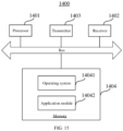
- FIG. 15 is a schematic diagram illustrating a network device 1400 according to an exemplary embodiment.
- the network device 1400 may be a base station.
- the network device 1400 may include: a processor 1401, a receiver 1402, a transmitter 1403, and a memory 1404.
- the receiver 1402, the transmitter 1403 and the memory 1404 are respectively connected to the processor 1401 through a bus.
- the processor 1401 includes one or more processing cores.
- the processor 1401 executes the method for receiving an SRS performed by the network device in the embodiments of the disclosure by running software programs and modules.
- the memory 1404 may be used to store software programs and modules.
- the memory 1404 can store an operating system 14041 and an application module 14042 required by at least one function.
- the receiver 1402 is used to receive communication data sent by other devices, and the transmitter 1403 is used to send communication data to other devices.
- An exemplary embodiment of the disclosure also provides a computer-readable storage medium.
- the computer-readable storage medium stores at least one instruction, at least one program segment, a code set or an instruction set.
- the at least one instruction, the at least one program segment, the code set or the instruction set is loaded and executed by the processor to implement the method for sending an SRS or the method for receiving an SRS in the above method embodiments.
- An exemplary embodiment of the disclosure also provides a computer program product including computer instructions.
- the computer instructions are stored in a computer-readable storage medium and can be read by a processor of a computer device from the computer-readable storage medium.
- the processor executes the computer instructions, the computer is caused to perform the method for sending an SRS or the method for receiving an SRS in the above method embodiments.
Landscapes
- Engineering & Computer Science (AREA)
- Signal Processing (AREA)
- Computer Networks & Wireless Communication (AREA)
- Mobile Radio Communication Systems (AREA)
Applications Claiming Priority (1)
| Application Number | Priority Date | Filing Date | Title |
|---|---|---|---|
| PCT/CN2022/079154 WO2023164909A1 (zh) | 2022-03-03 | 2022-03-03 | 发送srs的方法、接收srs的方法、装置、设备、介质及产品 |
Publications (2)
| Publication Number | Publication Date |
|---|---|
| EP4489337A1 true EP4489337A1 (de) | 2025-01-08 |
| EP4489337A4 EP4489337A4 (de) | 2026-01-07 |
Family
ID=87882865
Family Applications (1)
| Application Number | Title | Priority Date | Filing Date |
|---|---|---|---|
| EP22929358.4A Pending EP4489337A4 (de) | 2022-03-03 | 2022-03-03 | Srs-sendeverfahren und -vorrichtung, srs-empfangsverfahren und -vorrichtung, vorrichtung, medium und produkt |
Country Status (6)
| Country | Link |
|---|---|
| US (1) | US20250175301A1 (de) |
| EP (1) | EP4489337A4 (de) |
| JP (1) | JP7796245B2 (de) |
| KR (1) | KR20240151830A (de) |
| CN (1) | CN117015949A (de) |
| WO (1) | WO2023164909A1 (de) |
Families Citing this family (4)
| Publication number | Priority date | Publication date | Assignee | Title |
|---|---|---|---|---|
| US20230300012A1 (en) * | 2022-03-16 | 2023-09-21 | Samsung Electronics Co., Ltd. | Method and apparatus for an srs procedure |
| IL294194A (en) * | 2022-06-22 | 2024-01-01 | Qualcomm Inc | Dynamic adaptation of sounding reference signal frequency domain parameters |
| WO2025138281A1 (zh) * | 2023-12-29 | 2025-07-03 | 北京小米移动软件有限公司 | 资源配置方法、终端、网络设备、通信装置、系统及介质 |
| CN120710548A (zh) * | 2024-03-26 | 2025-09-26 | 中国移动通信有限公司研究院 | 一种信息传输方法、相关设备、存储介质及计算机产品 |
Family Cites Families (15)
| Publication number | Priority date | Publication date | Assignee | Title |
|---|---|---|---|---|
| CN102075274B (zh) * | 2011-01-31 | 2016-09-28 | 中兴通讯股份有限公司 | 一种测量参考信号的多天线参数的配置方法及装置 |
| WO2018126474A1 (en) * | 2017-01-09 | 2018-07-12 | Qualcomm Incorporated | Transmitting multiplexed sounding reference signal ports in new radio |
| CN109257150B (zh) * | 2017-07-14 | 2021-08-17 | 维沃移动通信有限公司 | 资源映射方法、网络设备、终端及计算机可读存储介质 |
| CN111213417B (zh) * | 2017-08-11 | 2022-11-04 | 上海诺基亚贝尔股份有限公司 | 增强的探测参考信号传输 |
| CN109586869B (zh) * | 2017-09-29 | 2021-08-06 | 中国移动通信有限公司研究院 | Srs发送方法、相位差处理方法、通信设备及存储介质 |
| CN111464275B (zh) * | 2019-01-21 | 2023-06-27 | 中国移动通信有限公司研究院 | 探测参考信号的发送配置、发送方法、终端及网络设备 |
| CN111865524B (zh) * | 2019-04-29 | 2022-02-11 | 华为技术有限公司 | 传输探测参考信号srs的方法和装置 |
| WO2021002018A1 (ja) * | 2019-07-04 | 2021-01-07 | 株式会社Nttドコモ | 端末及び無線通信方法 |
| WO2021012981A1 (en) * | 2019-07-22 | 2021-01-28 | Guangdong Oppo Mobile Telecommunications Corp., Ltd. | Methods and apparatuses of sounding reference signal transmission |
| CN111835488B (zh) * | 2019-08-15 | 2022-12-23 | 维沃移动通信有限公司 | 一种确定天线端口映射方法和终端 |
| CN111901079B (zh) * | 2020-01-03 | 2024-10-29 | 中兴通讯股份有限公司 | 参考信号发送、接收方法、装置、通信节点及介质 |
| CN111758272B (zh) * | 2020-05-22 | 2023-09-26 | 北京小米移动软件有限公司 | Srs资源配置方法、srs资源确定方法和装置 |
| EP4201017A1 (de) * | 2020-08-18 | 2023-06-28 | Ntt Docomo, Inc. | Verfahren zur gemeinsamen nutzung von srs-ressourcen zwischen srs-ressourcensätzen verschiedener verwendungen und zugehöriges benutzergerät |
| WO2023091417A1 (en) * | 2021-11-17 | 2023-05-25 | Intel Corporation | Enhanced sounding reference signal (srs) operation for fifth-generation (5g) systems |
| CN116489782A (zh) * | 2022-01-14 | 2023-07-25 | 维沃移动通信有限公司 | Srs端口映射方法、装置及终端 |
-
2022
- 2022-03-03 US US18/843,092 patent/US20250175301A1/en active Pending
- 2022-03-03 KR KR1020247031455A patent/KR20240151830A/ko active Pending
- 2022-03-03 EP EP22929358.4A patent/EP4489337A4/de active Pending
- 2022-03-03 CN CN202280000675.9A patent/CN117015949A/zh active Pending
- 2022-03-03 JP JP2024551943A patent/JP7796245B2/ja active Active
- 2022-03-03 WO PCT/CN2022/079154 patent/WO2023164909A1/zh not_active Ceased
Also Published As
| Publication number | Publication date |
|---|---|
| WO2023164909A1 (zh) | 2023-09-07 |
| JP2025512685A (ja) | 2025-04-22 |
| JP7796245B2 (ja) | 2026-01-08 |
| KR20240151830A (ko) | 2024-10-18 |
| CN117015949A (zh) | 2023-11-07 |
| EP4489337A4 (de) | 2026-01-07 |
| US20250175301A1 (en) | 2025-05-29 |
Similar Documents
| Publication | Publication Date | Title |
|---|---|---|
| EP4489337A1 (de) | Srs-sendeverfahren und -vorrichtung, srs-empfangsverfahren und -vorrichtung, vorrichtung, medium und produkt | |
| KR20220150851A (ko) | D2d 통신을 위한 d2d 데이터 자원을 결정하는 방법 및 장치 | |
| EP3393167B1 (de) | Ressourcenzuweisungsverfahren und -vorrichtung und basisstation | |
| EP2822303A2 (de) | Funkkommunikationsvorrichtung und Funkkommunikationsverfahren | |
| EP3579469B1 (de) | Drahtloskommunikationsverfahren und -vorrichtung | |
| US20220217684A1 (en) | Method and apparatus for using sidelink bandwidth part | |
| US9191168B2 (en) | Method and apparatus for aperiodically transmitting sounding reference signal | |
| CN106160988A (zh) | 一种pucch传输方法及装置 | |
| EP4489322A1 (de) | Srs-sendeverfahren und -vorrichtung, srs-empfangsverfahren und -vorrichtung, vorrichtung, medium und produkt | |
| JP2023508203A (ja) | 通信方法および装置 | |
| US20250167957A1 (en) | Method and apparatus for sending srss, method and apparatus for receiving srss, device, medium and product | |
| KR102229592B1 (ko) | 데이타 전송 방법 및 장치 | |
| CN111869281B (zh) | 定位测距方法、装置、通信设备及存储介质 | |
| EP4496249A1 (de) | Verfahren und vorrichtung zur bestimmung der assoziationsbeziehung von uplink-ptrs-ports, medium und produkt | |
| EP3459299B1 (de) | Verfahren und vorrichtung zur sequenzerzeugung | |
| EP3636019B1 (de) | Kommunikationsvorrichtung und -verfahren zur anzeige einer präferenz auf der basis des geräteenergieverbrauchs oder der leistung von trägern | |
| CN109644445B (zh) | 一种探测参考信号的处理方法和基站以及用户设备 | |
| CN113892249B (zh) | 用于数据调制中的伪序列插入的方法及装置 | |
| US11962521B2 (en) | Radio communication apparatus, method, program, non-transitory computer readable recording medium, and system | |
| US12407544B2 (en) | Method and device for channel estimation | |
| RU2843954C2 (ru) | Способ и устройство для передачи SRS, способ и устройство для приема SRS, а также оборудование, носитель данных и продукт | |
| CN108111277A (zh) | 上行信号发送的配置、上行信号的发送方法、装置及系统 | |
| EP4224757A1 (de) | Verfahren und vorrichtung zur bestimmung einer frequenzdomänenposition, vorrichtung und speichermedium | |
| KR20250004609A (ko) | 사운딩 기준 신호의 콤 오프셋 호핑 및 순환 시프트 호핑 |
Legal Events
| Date | Code | Title | Description |
|---|---|---|---|
| STAA | Information on the status of an ep patent application or granted ep patent |
Free format text: STATUS: THE INTERNATIONAL PUBLICATION HAS BEEN MADE |
|
| PUAI | Public reference made under article 153(3) epc to a published international application that has entered the european phase |
Free format text: ORIGINAL CODE: 0009012 |
|
| STAA | Information on the status of an ep patent application or granted ep patent |
Free format text: STATUS: REQUEST FOR EXAMINATION WAS MADE |
|
| 17P | Request for examination filed |
Effective date: 20241001 |
|
| AK | Designated contracting states |
Kind code of ref document: A1 Designated state(s): AL AT BE BG CH CY CZ DE DK EE ES FI FR GB GR HR HU IE IS IT LI LT LU LV MC MK MT NL NO PL PT RO RS SE SI SK SM TR |
|
| DAV | Request for validation of the european patent (deleted) | ||
| DAX | Request for extension of the european patent (deleted) | ||
| A4 | Supplementary search report drawn up and despatched |
Effective date: 20251208 |
|
| RIC1 | Information provided on ipc code assigned before grant |
Ipc: H04L 5/00 20060101AFI20251202BHEP Ipc: H04B 7/06 20060101ALI20251202BHEP |