EP4489322A1 - Srs-sendeverfahren und -vorrichtung, srs-empfangsverfahren und -vorrichtung, vorrichtung, medium und produkt - Google Patents
Srs-sendeverfahren und -vorrichtung, srs-empfangsverfahren und -vorrichtung, vorrichtung, medium und produkt Download PDFInfo
- Publication number
- EP4489322A1 EP4489322A1 EP22929304.8A EP22929304A EP4489322A1 EP 4489322 A1 EP4489322 A1 EP 4489322A1 EP 22929304 A EP22929304 A EP 22929304A EP 4489322 A1 EP4489322 A1 EP 4489322A1
- Authority
- EP
- European Patent Office
- Prior art keywords
- srs
- parameter
- max
- cyclic shift
- resource
- Prior art date
- Legal status (The legal status is an assumption and is not a legal conclusion. Google has not performed a legal analysis and makes no representation as to the accuracy of the status listed.)
- Pending
Links
Images


Classifications
-
- H—ELECTRICITY
- H04—ELECTRIC COMMUNICATION TECHNIQUE
- H04L—TRANSMISSION OF DIGITAL INFORMATION, e.g. TELEGRAPHIC COMMUNICATION
- H04L5/00—Arrangements affording multiple use of the transmission path
- H04L5/003—Arrangements for allocating sub-channels of the transmission path
- H04L5/0048—Allocation of pilot signals, i.e. of signals known to the receiver
- H04L5/0051—Allocation of pilot signals, i.e. of signals known to the receiver of dedicated pilots, i.e. pilots destined for a single user or terminal
-
- H—ELECTRICITY
- H04—ELECTRIC COMMUNICATION TECHNIQUE
- H04L—TRANSMISSION OF DIGITAL INFORMATION, e.g. TELEGRAPHIC COMMUNICATION
- H04L27/00—Modulated-carrier systems
- H04L27/26—Systems using multi-frequency codes
- H04L27/2601—Multicarrier modulation systems
- H04L27/2602—Signal structure
- H04L27/2605—Symbol extensions, e.g. Zero Tail, Unique Word [UW]
-
- H—ELECTRICITY
- H04—ELECTRIC COMMUNICATION TECHNIQUE
- H04L—TRANSMISSION OF DIGITAL INFORMATION, e.g. TELEGRAPHIC COMMUNICATION
- H04L27/00—Modulated-carrier systems
- H04L27/26—Systems using multi-frequency codes
- H04L27/2601—Multicarrier modulation systems
- H04L27/2602—Signal structure
- H04L27/261—Details of reference signals
- H04L27/2613—Structure of the reference signals
-
- H—ELECTRICITY
- H04—ELECTRIC COMMUNICATION TECHNIQUE
- H04L—TRANSMISSION OF DIGITAL INFORMATION, e.g. TELEGRAPHIC COMMUNICATION
- H04L5/00—Arrangements affording multiple use of the transmission path
- H04L5/0001—Arrangements for dividing the transmission path
- H04L5/0014—Three-dimensional division
- H04L5/0023—Time-frequency-space
-
- H—ELECTRICITY
- H04—ELECTRIC COMMUNICATION TECHNIQUE
- H04L—TRANSMISSION OF DIGITAL INFORMATION, e.g. TELEGRAPHIC COMMUNICATION
- H04L5/00—Arrangements affording multiple use of the transmission path
- H04L5/0091—Signalling for the administration of the divided path, e.g. signalling of configuration information
- H04L5/0094—Indication of how sub-channels of the path are allocated
-
- H—ELECTRICITY
- H04—ELECTRIC COMMUNICATION TECHNIQUE
- H04W—WIRELESS COMMUNICATION NETWORKS
- H04W76/00—Connection management
- H04W76/20—Manipulation of established connections
-
- H—ELECTRICITY
- H04—ELECTRIC COMMUNICATION TECHNIQUE
- H04B—TRANSMISSION
- H04B7/00—Radio transmission systems, i.e. using radiation field
- H04B7/02—Diversity systems; Multi-antenna system, i.e. transmission or reception using multiple antennas
- H04B7/04—Diversity systems; Multi-antenna system, i.e. transmission or reception using multiple antennas using two or more spaced independent antennas
- H04B7/06—Diversity systems; Multi-antenna system, i.e. transmission or reception using multiple antennas using two or more spaced independent antennas at the transmitting station
Definitions
- the disclosure relates to the field of communications, particularly to a method and an apparatus for sending a sounding reference signal (SRS), a method and an apparatus for receiving an SRS, a device, a medium and a product.
- SRS sounding reference signal
- an uplink Sounding Reference Signal may be used to measure and estimate channel quality of an uplink channel.
- a plurality of antenna ports may be configured for a user equipment (UE), and the UE supports the transmission of the SRS for up to 4 antenna ports.
- UE user equipment
- Embodiments of the disclosure provide a method and an apparatus for sending a Sounding Reference Signal (SRS), a method and an apparatus for receiving an SRS, a device, a medium, and a product.
- SRS Sounding Reference Signal
- the technical solution is as follows: According to an aspect of the disclosure, a method for sending an SRS is provided. The method is performed by a terminal. The method includes: configuring and sending an SRS of 8 antenna ports on one SRS resource, in which the 8 antenna ports are mapped onto same physical resources.
- a method for receiving an SRS is provided.
- the method is performed by a network device.
- the method includes: receiving an SRS of 8 antenna ports sent, on one SRS resource, by a terminal, in which the 8 antenna ports are mapped onto same physical resources.
- an apparatus for sending an SRS includes: a first sending module, configured to configure and send an SRS of 8 antenna ports on one SRS resource, in which the 8 antenna ports are mapped onto same physical resources.
- an apparatus for receiving an SRS includes: a second receiving module, configured to receive an SRS of 8 antenna ports sent, on one SRS resource, by a terminal, in which the 8 antenna ports are mapped onto same physical resources.
- a terminal includes:
- a network device includes:
- a computer readable storage medium has at least one instruction, at least one program, a code set or an instruction set stored thereon.
- the at least one instruction, the at least one program, the code set or the instruction set are loaded and executed by the processor to oerfim the method for sending an SRS or the method for receiving an SRS according to the foregoing aspects.
- a computer program product (or a computer program) is provided.
- the computer program product includes computer instructions.
- the computer instructions are stored in a computer readable storage medium.
- a processor of a computer device reads the computer instructions from the computer readable storage medium.
- the processor executes the computer instructions, so that the computer device performs the method for sending an SRS or the method for receiving an SRS according to the foregoing aspects.
- the terminal may map the eight antenna ports onto the same physical resources, configure and send the SRS of the eight antenna ports on one SRS resource.
- the method is used to support the implementation of related functions in the case that the terminal uses eight transmit/sending antenna ports.
- the method is used to support the codebook based uplink channel quality detection in the case that the terminal uses the eight transmit/sending antenna ports, support the non-codebook based uplink channel quality detection in the case that the terminal uses the eight transmit/sending antenna ports, or support the downlink channel quality detection when performing the antenna switching in the case that the terminal uses the eight transmit/sending antenna ports.
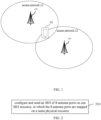
- FIG. 1 illustrates a block diagram illustrating a communication system according to an exemplary embodiment of the disclosure.
- the communication system may include access networks 12 and a user terminal 14.
- An access network 12 includes several network devices 120.
- the network device (also referred to as a network equipment) 120 may be a base station.
- the base station is a device deployed in an access network to provide a wireless communication function for the user terminal (referred to as "terminal" for short) 14.
- the base station may include various forms of macro base stations, micro base stations, relay stations, access points, and the like.
- the name of a device with a base station function may vary.
- LTE long term evolution
- eNodeB eNodeB
- 5G NR in 5G NR system
- the description of "base station” may vary.
- devices for providing the wireless communication function for the user terminal 14 is collectively referred to as a network device.
- the user terminal 14 may include all kinds of handheld devices with a wireless communication function, vehicle devices, wearable devices, computing devices or other processing devices connected to wireless modems, as well as various forms of user equipments (UEs), mobile stations (MS), terminal devices, and the like. For convenience of description, devices mentioned above is collectively referred to as a user terminal.
- the network device 120 and the user terminal 14 communicate with each other through some kind of air interface technology, for example, a Uu interface.
- Uplink communication refers to sending signals to the network device 120
- downlink communication refers to sending signals to the user terminal 14.
- GSM global system of mobile communication
- CDMA code division multiple access
- WCDMA wideband code division multiple access
- GPRS general packet radio service
- LTE long term evolution
- FDD frequency division duplex
- TDD LTE time division duplex
- LTE-A advanced long term evolution
- NR new radio
- UMTS universal mobile telecommunication system
- WiMAX worldwide interoperability for microwave access
- WLAN wireless local area network
- WiFi wireless fidelity
- next-generation communication system or other communication system and the like.
- a number of connections supported by a traditional communication system is limited, and the connections are also easy to implement.
- a mobile communication system not only supports traditional communications, but also supports, for example, device-to-device (D2D) communication, machine-to-machine (M2M) communication, machine type communication (MTC), vehicle-to-vehicle (V2V) communication, and a vehicle-to-everything (V2X) system.
- D2D device-to-device
- M2M machine-to-machine
- MTC machine type communication
- V2V vehicle-to-vehicle
- V2X vehicle-to-everything
- FIG. 2 illustrates a flowchart illustrating a method for sending an SRS according to an exemplary embodiment of the disclosure. The method is performed by a terminal in the communication system illustrated in FIG. 1 . The method includes the following.
- an SRS of 8 antenna ports are configured and sent on one SRS resource, and the eight antenna ports are mapped onto same physical resources.
- the terminal maps one SRS resource on same physical resources (PRs) and configures and sends the SRS of the eight antenna ports on the SRS resource.
- PRs physical resources
- PR means contiguous carrier resources in a frequency domain.
- One physical resource block (PRB) corresponds to 12 contiguous carriers in the frequency domain and 1 slot in a time domain.
- the uplink channel includes at least one of a Physical Uplink Control Channel (PUCCH) or a Physical Uplink Shared Channel (PUSCH).
- the terminal may map one SRS resource onto the PRs of the PUCCH and/or the PUSCH.
- the terminal maps one SRS resource onto the same physical resources based on configuration parameter(s).
- the configuration parameter(s) includes at least one of the following:
- the transmission comb parameter K TC is used to indicate a comb-shaped structure of the SRS resource in the frequency domain. That is, it is not the case that the SRS resource is mapped onto contiguous subcarriers.
- the transmission comb offset value k TC refers to an offset value for a subcarrier occupied by a first one of RE resource in one SRS resource, and the transmission comb offset value is a non-negative integer less than the transmission comb parameter.
- the bandwidth parameter means a bandwidth occupied by the SRS resource.
- the cyclic shift parameter means the number of bits of the cyclic shift for a sequence.
- the antenna port is a logical transmission channel defined by a reference signal, and the antenna port is mapped onto a physical antenna for signal transmission.
- the configuration parameter(s) may further include a length of a zadoff-chu (ZC) sequence.
- ZC zadoff-chu
- the length of the ZC sequence refers to a numerical value length of the ZC sequence.
- the terminal generates 8 SRS sequences based on the ZC sequence and carries the SRS of the 8 antenna ports through the 8 SRS sequences.
- the 8 antenna ports may be antenna ports mapped onto a same antenna panel or different antenna panels. That is, the 8 antenna ports are antenna ports mapped onto M antenna panels, where M is a positive integer less than or equal to 8. For example, four first antenna ports in the 8 antenna ports are mapped onto a first antenna panel and four second antenna ports are mapped onto a second antenna panel.
- OFDM Orthogonal Frequency-Division Multiplexing
- the above-mentioned “function of the SRS resource” is at least one of the following:
- the terminal may perform a codebook based uplink channel quality detection, a downlink channel quality detection when antenna switching is performed, or a non-codebook based uplink channel quality detection.
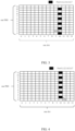
- the terminal maps one SRS resource onto one PRB.
- This SRS resource includes 6 RE resources 301, one RE resource 301 is determined in every two consecutive subcarriers, and two adjacent RE resources 301 are separated by one subcarrier.
- the 6 RE resources 301 each is located on a symbol 10 of one slot.
- the 6 RE resources 301 are respectively located on a subcarrier 0, a subcarrier 2, a subcarrier 4, a subcarrier 6, a subcarrier 8 and a subcarrier 10.
- the 8 antenna ports including a port 0, a port 1, a port 2, ..., a port 7 are mapped onto each RE resource 301.
- a transmission comb resource in FIG. 3 may occupy 1 OFDM symbol.
- the terminal may map the 8 antenna ports onto the same physical resources, and configure and send the SRS of the 8 antenna ports on one SRS resource.
- the method is used to support the implementation of related functions when the terminal uses 8 transmit/sending antenna ports.
- the method is used to support a codebook based uplink channel quality detection in the case that the terminal uses 8 transmit/sending antenna ports, sepport a non-codebook based uplink channel quality detection in the case that the terminal uses 8 transmit/sending antenna ports, or support a downlink channel quality detection when performing the antenna switching in the case that the terminal uses 8 transmit/sending antenna ports.
- a value range of the the transmission comb parameter K TC is ⁇ 2, 4, 8, 12 ⁇ . The following describes the cases of different values of K TC .
- the transmission comb offset value k TC corresponding to the SRS resource is a non-negative integer less than 2.
- the transmission comb offset value k TC may be equal to 0 or 1.
- the terminal maps one SRS resource onto one PRB.
- This SRS resource includes 6 RE resources 302, one RE resource 302 is determined in every two consecutive subcarriers, and two adjacent RE resources 302 are separated by one subcarrier.
- the 6 RE resources 302 each is located on the symbol 10 of one slot.
- the 6 RE resources 302 are respectively located on a subcarrier 1, a subcarrier 3, a subcarrier 5, a subcarrier 7, a subcarrier 9, and a subcarrier 11.
- the 8 antenna ports including the port 0, the port 1, the port 2, ..., the port 7 are mapped onto each RE resource 302.
- a transmission comb parameter in FIG. 4 may occupy 1 OFDM symbol.
- a maximum number of cyclic shift parameters supported by the transmission comb parameter is 8, and a value range of the n SRS cs is n SRS cs ⁇ 0,1 , ... , n SRS cs , max ⁇ 1 .
- the terminal uses all of the 8 cyclic shift parameters to generate the SRS resource.
- the maximum number of the cyclic shift parameters supported by the transmission comb parameter is 12, and the value range of the n SRS cs is n SRS cs ⁇ 0,1 , ... , n SRS cs , max ⁇ 1 .
- the terminal uses some cycle shift parameters among the 12 cyclic shift parameters to generate the SRS resource, that is, 8 cyclic shift parameters in the 12 cyclic shift parameters are actually used to generate the SRS resource.
- the transmission comb offset value k TC corresponding to the SRS resource is a non-negative integer less than 4.
- the transmission comb offset value k TC may be equal to 0, 1, 2, or 4.
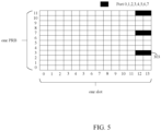
- the terminal maps one SRS resource onto one PRB.
- This SRS resource includes three groups of RE resources 303, one group of RE resources 303 is determined in every 4 consecutive subcarriers, and two adjacent groups of RE resources 303 are separated by 3 subcarriers.
- Each group of RE resources 303 includes two RE resources, and the three groups of RE resources 303 each is located on a symbol 12 and a symbol 13 of one slot.
- the transmission comb offset value k TC is equal to 3
- the three groups of RE resources 303 are respectively located on the subcarrier 3, the subcarrier 7, and the subcarrier 11.
- the 8 antenna ports including the port 0, the port 1, the port 2, ..., the port 7 are mapped onto each RE resource 303.
- the transmission comb resource in FIG. 5 may occupy 2 OFDM symbols.
- the maximum number of cyclic shift parameters supported by the transmission comb parameter is 8, and a value range of the n SRS cs is n SRS cs ⁇ 0,1 , ... , n SRS cs , max ⁇ 1 .
- the terminal uses all of the 8 cyclic shift parameters to generate the SRS resource.
- the maximum number of the cyclic shift parameters supported by the transmission comb parameter is 12, and the value range of the n SRS cs is n SRS cs ⁇ 0,1 , ... , n SRS cs , max ⁇ 1 .
- the terminal uses some cyclic shift parameters among 12 cyclic shift parameters to generate the SRS resource, that is, 8 cyclic shift parameters among the 12 cyclic shift parameters are actually used to generate the SRS resource.
- a bandwidth corresponding to the bandwidth parameter is greater than or equal to a bandwidth of 4 PRBs; or the bandwidth parameter is a multiple of the bandwidth of 4 PRBs; or the bandwidth corresponding to the bandwidth parameter is greater than or equal to a bandwidth of 6 PRBs; or the bandwidth parameter is a multiple of the bandwidth of 6 PRBs; or the bandwidth corresponding to the bandwidth parameter is greater than or equal to a bandwidth of 8 PRBs; or the bandwidth parameter is a multiple of the bandwidth of 8 PRBs.
- the value of the transmission comb offset value k TC corresponding to the SRS resource is a non-negative integer less than 8.
- the transmission comb offset value k TC may be equal to 0, 1, 2, ..., or 7.
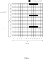
- the terminal maps one SRS resource onto two PRBs.
- This SRS resource includes three groups of RE resources 304, one group of RE resources 304 is determined in every 8 consecutive subcarriers, and two adjacent groups of RE resources 304 are separated by 7 subcarriers.
- Each group of RE resources 304 includes 4 RE resources, and the three groups of RE resources 304 each is located on a symbol 8, a symbol 9, the symbol 10, and a symbol 11 of one slot.
- the three groups of RE resources 304 are respectively located on a subcarrier 7 of a first PRB, a subcarrier 3 of a second PRB and a subcarrier 11 of the second PRB.
- the 8 antenna ports including the port 0, the port 1, the port 2, ..., the port 7 are mapped onto each group of RE resources 304.
- the transmission comb resource in FIG. 6 may occupy 4 OFDM symbols.
- the maximum number of cyclic shift parameters supported by the transmission comb parameter is 8, and a value range of the n SRS cs is n SRS cs ⁇ 0,1 , ... , n SRS cs , max ⁇ 1 .
- the terminal uses all of the 8 cyclic shift parameters to generate the SRS resource.
- the maximum number of the cyclic shift parameters supported by the transmission comb parameter is 12, and the value range of the n SRS cs is n SRS cs ⁇ 0,1 , ... , n SRS cs , max ⁇ 1 .
- the terminal uses some cyclic shift parameters among the 12 cyclic shift parameters to generate the SRS resource, that is, the SRS resource is actually generated by using 8 cyclic shift parameters among the 12 cyclic shift parameters.
- the value of the transmission comb offset value k TC corresponding to the SRS resource is a non-negative integer less than 12.
- the transmission comb offset value k TC may be equal to 0, 1, 2, ..., or 11.
- the terminal maps one SRS resource onto two PRBs.
- This SRS resource includes 2 RE resources 305, one RE resource 305 is determined in every 12 consecutive subcarriers, and two adjacent RE resources 305 are separated by 11 subcarriers.
- the two RE resources 305 each is located on the symbol 10 of one slot.
- the two RE resources 305 are respectively located on a subcarrier 11 of a first PRB and a subcarrier 11 of a second PRB.
- the 8 antenna ports including the port 0, the port 1, the port 2, ..., the port 7 are mapped onto each RE resource 305.
- the transmission comb resource in FIG. 7 may occupy 1 OFDM symbol.
- the maximum number of cyclic shift parameters supported by the transmission comb parameter is 8, and a value range of the n SRS cs is n SRS cs ⁇ 0,1 , ... , n SRS cs , max ⁇ 1 .
- the terminal uses all of the 8 cyclic shift parameters to generate the SRS resource.
- the maximum number of the cyclic shift parameters supported by the transmission comb parameter is 12, and the value range of the n SRS cs is n SRS cs ⁇ 0,1 , ... , n SRS cs , max ⁇ 1 .
- the terminal uses some cyclic shift parameters among the 12 cyclic shift parameters to generate the SRS resource, that is, the SRS resource is actually generated by using 8 cyclic shift parameters among the 12 cyclic shift parameters.
- the bandwidth corresponding to the bandwidth parameter is greater than or equal to the bandwidth of 6 PRBs; or the bandwidth parameter is a multiple of the bandwidth of 6 PRBs; or the bandwidth corresponding to the bandwidth parameter is greater than or equal to the bandwidth of 8 PRBs; or the bandwidth parameter is a multiple of the bandwidth of 8 PRBs.
- more than one SRS resource can be mapped onto more than one PRB to avoid that the measurement result of the uplink channel quality is unrepresentativecaused by a small number of SRS resources.
- an implementation of mapping the SRS resource by using a larger transmission comb parameter 8 or 12 is provided to support the sending of the SRS of the 8 antenna ports.
- FIG. 8 is a flowchart illustrating a method for receiving an SRS according to an exemplary embodiment of the disclosure. The method is performed by a network device in the communication system in FIG. 1 . The method includes the following.
- an SRS of 8 antenna ports sent on one SRS resource by a terminal is received, in which the 8 antenna ports are mapped onto same physical resources.
- the network device receives the SRS of the 8 antenna ports from the same physical resources.
- the above-mentioned "physical resources" means consecutive carrier resources in a frequency domain.
- One PRB corresponds to 12 consecutive carriers in the frequency domain and one slot in the time domain.
- an uplink channel includes at least one of a PUCCH or a PUSCH.
- the terminal may receive the SRS of the 8 antenna ports on the physical resources of the PUCCH and/or the PUSCH.
- the received SRS of the 8 antenna ports is an SRS of the 8 antenna ports configured and sent by the terminal on one SRS resource.
- the method provides support for sending of the SRS of the 8 antenna ports.
- the method is used to support the implementation of related functions in the case that the terminal uses 8 transmit/sending antenna ports.
- the method is used to support a codebook based uplink channel quality detection in the case that the terminal uses 8 transmit/sending antenna ports, support a non-codebook based uplink channel quality detection in the case that the terminal uses 8 transmit/sending antenna ports, or support a downlink channel quality detection when performing the antenna switching in the case that the terminal uses 8 transmit/sending antenna ports.
- the terminal configures and sends the SRS of the 8 antenna ports on one SRS resource based on configuration parameter(s).
- the configuration parameter(s) may be configured by the network device for the terminal.
- FIG. 9 illustrates a flowchart of a method for configuring parameters according to an exemplary embodiment of the disclosure. The method is performed by a network device in the communication system illustrated in FIG. 1 . The method includes the following.
- the network device sends configuration parameter(s) corresponding to the SRS resource to the terminal.
- the configuration parameter(s) includes/include: a transmission comb parameter K TC of the SRS resource, where K TC is equal to 2.
- the configuration parameters may further include at least one of:
- the configuration parameter(s) includes/include: the transmission comb parameter K TC of the SRS resource, where K TC is equal to 4.
- the configuration parameters may further include at least one of:
- the configuration parameter(s) includes/include: the transmission comb parameter K TC of the SRS resource, where K TC is equal to 8.
- the configuration parameters may further include at least one of:
- the configuration parameter(s) includes/include: the transmission comb parameter K TC of the SRS resource, where K TC is equal to 12.
- the configuration parameters may further include at least one of:
- the configuration parameters further include a bandwidth parameter.
- the bandwidth parameter is greater than or equal to a bandwidth of 4 PRBs; or the bandwidth parameter is a multiple of the bandwidth of 4 PRBs; or the bandwidth parameter is greater than or equal to a bandwidth of 6 PRBs; or the bandwidth parameter is a multiple of the bandwidth of 6 PRBs; or the bandwidth parameter is greater than or equal to a bandwidth of 8 PRBs; or the bandwidth parameter is a multiple of the bandwidth of 8 PRBs. That is, when K TC is equal to 2 or 4, a minimum bandwidth parameter configured for the SRS resource is 4 PRBs.
- the configuration parameters further include a bandwidth parameter.
- the bandwidth parameter is greater than or equal to a bandwidth of 6 PRBs; or the bandwidth parameter is a multiple of the bandwidth of 6 PRBs; or the bandwidth parameter is greater than or equal to a bandwidth of 8 PRBs; or the bandwidth parameter is a multiple of the bandwidth of 8 PRBs. That is, when K TC is equal to 8 or 12, a minimum bandwidth parameter configured for the SRS resource is 6 PRBs.
- the network device determines a first bandwidth that is greater than or equal to 6 PRBs and sends this configuration parameter, i.e. the first bandwidth, to the terminal.
- the network device determines a second bandwidth which is the multiple of 8 PRBs and sends this configuration parameter, i.e. the second bandwidth, to the terminal.
- the configuration parameters further include: a cyclic shift parameter n SRS cs of the SRS, where the n SRS cs is a non-negative integer.
- the network device configures the cyclic shift parameter n SRS cs for the terminal; or the network device configures 8 cyclic shift parameters corresponding to the 8 antenna ports for the terminal.
- the network device before receiving the SRS, the network device sends some or all of the configuration parameters corresponding to the SRS resource to the terminal.
- all or some of the above configuration parameters are configured by the network devie for the terminal through a higher layer signaling.
- all or some of the above configuration parameters are carried in a Radio Resource Control (RRC).
- RRC Radio Resource Control
- the configuration parameters corresponding to the SRS resource may also be defined by a protocol or determined by the terminal.
- the terminal determines the transmission comb parameter K TC based on its own requirement on an uplink transmission rate, and/or determines the transmission comb parameter K TC based on its own requirement on an uplink transmission quality.
- the terminal may actually use all or part of the cyclic shift parameters to generate the SRS resource based on its own requirement. For example, if the maximum number of the cyclic shift parameters supported by the transmission comb parameter is 8 and the terminal sends SRS of 4 antenna ports on the SRS resource, then only 4 cyclic shift parameters in the 8 cyclic shift parameters are used to generate the SRS resource.
- the terminal if the network device configures a cyclic shift parameter through a higher layer signaling, then the terminal generates SRS sequences corresponding to the 8 ports based on this cyclic shift parameter. Or, all the cyclic shift parameters used to generate the SRS resource are defined by the protocol.
- the terminal receives the configuration parameter(s) corresponding to the SRS resource sent by the network device and performs the step 210 based on the configuration parameter(s).
- the network device configures the configuration parameter(s) corresponding to the SRS resource for the terminal, such that the terminal may more efficiently configure and send the SRS.
- the network device configures some or all of initial configuration parameters for the terminal and subsequently updates some or all of the configuration parameters configured by the network device. For example, the network device periodically updates some or all of the configuration parameters used when sending the SRS.
- the network device updates the transmission comb parameter for the terminal every hour; or the network device updates the transmission comb parameter for the terminal based on a change of the network environment.
- the SRS transmission is more flexible, different communication requirements may be met and the communication efficiency may be improved.
- antenna ports for sending the SRS are extended, and the method is as follows.
- Method 1 the transmission comb parameter is equal to 2 or 4, which is directly used to support the newly defined SRS of 8 antenna ports.
- Method 2 the transmission comb parameter is equal to 8, and the supported maximum number of cyclic shift parameters is expanded to 8 or 12.
- n SRS cs , max 8
- RE resource element
- Method 3 the transmission comb parameter is equal to 12, and the supported maximum number of cyclic shift parameters is extended to 8 or 12.
- RE resource element
- n SRS cs , i n SRS cs + n SRS cs , max p i ⁇ 1000 N ap SRS mod n SRS cs , max ;
- the bandwidth parameter (that is, an SRS configuration bandwidth) in the method 3 is greater than or equal to 6 PRBs; or the bandwidth parameter is greater than or equal to 8 PRBs.
- the transmission comb offset value is notified to the terminal by the network device through the RRC signaling.
- the terminal may map the 8 antenna ports onto the same physical resources, and configure and send the SRS of the 8 antenna ports on one SRS resource.
- the method is used to support the implementation of related functions in the case that the terminal uses 8 transmit/sending antenna ports.
- the method is used to support a codebook based uplink channel quality detection in the case that the terminal uses 8 transmit/sending antenna ports, support a non-codebook based uplink channel quality detection in the case that the terminal uses 8 transmit/sending antenna ports, or support a downlink channel quality detection when performing the antenna switching in the case that the terminal uses 8 transmit/sending antenna ports.
- FIG. 10 is a block diagram illustrating an apparatus for sending an SRS according to an exemplary embodiment of the disclosure.
- the apparatus may be implemented as part or all of a UE by using software, hardware, or a combination of the two.
- the apparatus includes a first sending module 510.
- the first sending module 510 is configured to configure and send an SRS of 8 antenna ports on one SRS resource, in which the 8 antenna ports are mapped onto same physical resources.
- a transmission comb parameter K TC of the SRS resource is equal to 8.
- a transmission comb offset value k TC corresponding to the SRS resource is a non-negative integer less than 8.
- a maximum number n SRS cs , max of cyclic shift parameters supported by the transmission comb parameter is 8, where a value range of the n SRS cs , max is n SRS cs ⁇ 0,1 , ... , n SRS cs , max ⁇ 1 .
- the SRS resource is generated by using all of the 8 cyclic shift parameters.
- a maximum number n SRS cs , max of cyclic shift parameters supported by the transmission comb parameter is 12, where the value range of the n SRS cs , max is n SRS cs ⁇ 0,1 , ... , n SRS cs , max ⁇ 1 .
- the SRS resource is generated using some cyclic shift parameters among the 12 cyclic shift parameters.
- the transmission comb parameter K TC of the SRS resource is equal to 12.
- a transmission comb offset value k TC corresponding to the SRS resource is a non-negative integer less than 12.
- a maximum number n SRS cs , max of cyclic shift parameters supported by the transmission comb parameter is 8, where a value range of the n SRS cs , max is n SRS cs ⁇ 0,1 , ... , n SRS cs , max ⁇ 1 .
- the SRS resource is generated by using all of the 8 cyclic shift parameters.
- a maximum number n SRS cs , max of cyclic shift parameters supported by the transmission comb parameter is 12, where the value range of the n SRS cs , max is n SRS cs ⁇ 0,1 , ... , n SRS cs , max ⁇ 1 .
- the SRS resource is generated by using some cyclic shift parameters among the 12 cyclic shift parameters.
- the bandwidth parameter is greater than or equal to a bandwidth of 6 PRBs; or
- the transmission comb parameter of the SRS resource is equal to 2; or the transmission comb parameter is equal to 4.
- the apparatus further includes: a first receiving module 520, configured to receive configuration parameter(s) corresponding to the SRS resource sent by the network device.
- the configuration parameter(s) corresponding to the SRS resource includes /include at least one of:
- the apparatus further includes: a first receiving module 520, configured to receive a cyclic shift parameter n SRS cs of the SRS configured by the network device for the terminal, where n SRS cs is a non-negative integer.
- the transmission comb offset value corresponding to the SRS resource is carried in an RRC signalling.
- a function of the SRS resource is one of:
- FIG. 11 is a block diagram illustrating an apparatus for receiving an SRS according to an exemplary embodiment of the disclosure.
- the apparatus may be implemented as part or all of a network device by using software, hardware, or a combination of the two.
- the apparatus includes a second receiving module 610.
- the second receiving module 610 is configured to receive an SRS of 8 antenna ports sent on one SRS resource by a terminal.
- the 8 antenna ports are mapped onto same physical resources.
- the apparatus includes a second sending module 620.
- the second sending module 620 is configured to send configuration parameter(s) corresponding to the SRS resource to the terminal.
- the configuration parameter(s) includes/include: a transmission comb parameter K TC of the SRS resource, where K TC is equal to 8.
- the configuration parameter(s) includes/include: a transmission comb offset value k TC corresponding to the SRS resource, where k TC is a non-negative integer less than 8.
- a maximum number n SRS cs , max of cyclic shift parameters supported by the transmission comb parameter is 8, and a value range of the n SRS cs , max is n SRS cs ⁇ 0,1 , ... , n SRS cs , max ⁇ 1 .
- the SRS resource is generated by using all of the 8 cyclic shift parameters.
- a maximum number n SRS cs , max of cyclic shift parameters supported by the transmission comb parameter is 12, and the value range of the n SRS cs , max is n SRS cs ⁇ 0,1 , ... , n SRS cs , max ⁇ 1 .
- the SRS resource is generated by using some cyclic shift parameters among the 12 cyclic shift parameters.
- the configuration parameter(s) includes/include: the transmission comb parameter K TC of the SRS resource, where K TC is equal to 12.
- the configuration parameter(s) includes/include: the transmission comb offset value k TC corresponding to the SRS resource, where k TC is a non-negative integer less than 12.
- a maximum number n SRS cs , max of cyclic shift parameters supported by the transmission comb parameter is 8, and a value range of the n SRS cs , max is n SRS cs ⁇ 0,1 , ... , n SRS cs , max ⁇ 1 .
- the SRS resource is generated by using all of the 8 cyclic shift parameters.
- a maximum number n SRS cs , max of cyclic shift parameters supported by the transmission comb parameter is 12, and the value range of the n SRS cs , max is n SRS cs ⁇ 0,1 , ... , n SRS cs , max ⁇ 1 .
- the SRS resource is generated using some cyclic shift parameters among the 12 cyclic shift parameters.
- the configuration parameter(s) includes/include: a bandwidth parameter corresponding to the SRS.
- the bandwidth parameter is greater than or equal to a bandwidth of 6 PRBs; or the bandwidth parameter is a multiple of 6 PRBs; or the bandwidth parameter is greater than or equal to a bandwidth of 8 PRBs; or the bandwidth parameter is a multiple of 8 PRBs.
- the configuration parameter(s) includes/include: the transmission comb parameter K TC of the SRS resource, where K TC is equal to 2 or 4.
- the configuration parameter(s) includes/include: a cyclic shift parameter n SRS cs of the SRS, where n SRS cs is a non-negative integer.
- the apparatus includes: a second sending module 620, configured to send the transmission comb offset value corresponding to the SRS resource to the terminal through an RRC signalling.
- FIG. 12 is a block diagram illustrating an apparatus for configuring parameters according to an exemplary embodiment of the disclosure.
- the apparatus may be implemented as part or all of a network device by using software, hardware, or a combination of the two.
- the apparatus includes a third sending module 630.
- the third sending module 630 is configured to send configuration parameter(s) corresponding to an SRS resource to the terminal.
- the configuration parameter(s) includes/include: a transmission comb parameter of the SRS resource, where the transmission comb parameter is equal to 8.
- the configuration parameter(s) includes/include: a transmission comb parameter K TC of the SRS resource, where K TC is equal to 8.
- a maximum number n SRS cs , max of cyclic shift parameters supported by the transmission comb parameter is 8, and a value range of the n SRS cs , max is n SRS cs ⁇ 0,1 , ... , n SRS cs , max ⁇ 1 .
- the SRS resource is generated by using all of the 8 cyclic shift parameters.
- a maximum number n SRS cs , max of cyclic shift parameters supported by the transmission comb parameter is 12, and the value range of of n SRS cs , max is n SRS cs ⁇ 0,1 , ... , n SRS cs , max ⁇ 1 .
- the SRS resource is generated by using some cyclic shift parameters among the 12 cyclic shift parameters.
- the configuration parameter(s) includes/include: the transmission comb parameter K TC of the SRS resource, where K TC is equal to 12.
- the configuration parameter(s) includes/include: the transmission comb offset value k TC corresponding to the SRS resource, where k TC is a non-negative integer less than 12.
- a maximum number n SRS cs , max of cyclic shift parameters supported by the transmission comb parameter is 8, and the value range of the n SRS cs , max is n SRS cs ⁇ 0,1 , ... , n SRS cs , max ⁇ 1 .
- the SRS resource is generated by using all of the 8 cyclic shift parameters.
- the maximum number n SRS cs , max of cyclic shift parameters supported by the transmission comb parameter is 12, and the value range of the n SRS cs , max is n SRS cs ⁇ 0,1 , ... , n SRS cs , max ⁇ 1 .
- the SRS resource is generated by using some cyclic shift parameters among the 12 cyclic shift parameters.
- the configuration parameter(s) includes/include: a bandwidth parameter corresponding to the SRS.
- the bandwidth parameter is greater than or equal to a bandwidth of 6 PRBs; or the bandwidth parameter is a multiple of 6 PRBs; or the bandwidth parameter is greater than or equal to a bandwidth of 8 PRBs; or the bandwidth parameter is a multiple of 8 PRBs.
- the configuration parameter(s) includes/include: the transmission comb parameter K TC of the SRS resource, where K TC is equal to 2 or 4.
- the configuration parameter(s) includes/include: a cyclic shift parameter n SRS cs of the SRS, where n SRS cs is a non-negative integer.
- FIG. 13 is a structural diagram illustrating a UE according to an exemplary embodiment.
- the UE includes a processor 701, a receiver 702, a transmitter 703, a memory 704 and a bus 705.
- the processor 701 includes one or more processing cores, and the processor 701 executes various function applications and information processing by running a software program or a module.
- the receiver 702 and the transmitter 703 may be implemented as a communication component, which may be a communication chip.
- the memory 704 is communicatively coupled to the processor 701 through the bus 705.
- the memory 704 may be configured to store at least one instruction, and the processor 701 is configured to execute the at least one instruction to implement all blocks in above embodiments.
- the memory 704 may be implemented by any type of volatile or non-volatile storage device or their combination.
- the volatile or non-volatile storage device includes but not limited to a magnetic disk or an optical disk, an electrically erasable programmable read only memory (EEPROM), an erasable programmable read only memory (EPROM), a static random-access memory (SRAM), a read only memory (ROM), a magnetic memory, a flash memory and a programmable read only memory (PROM).
- a non-transitory computer readable storage medium includes instructions, such as the memory including instructions.
- the instructions may be executed by the processor of the UE to perform the above methods for sending an SRS.
- the non-transitory computer readable storage medium may be a ROM, a random-access memory (RAM), a compact disc ROM (CD ROM), a magnetic tape, a floppy disk, an optical data storage device, or the like.
- a non-transitory computer readable storage medium is further provided.
- the instructions in the non-transitory computer readable storage medium are executed by the processor of the UE, the UE is caused to execute the methods for sending an SRS.
- FIG. 14 is a block diagram illustrating a network device 800 according to an example embodiment.
- the network device 800 may be a base station.
- the network device 800 may include a processor 801, a receiver 802, a transmitter 803 and a memory 804.
- the receiver 802, the transmitter 803 and the memory 804 are connected to a processor 801 through a bus.
- the processor 801 include one or more processing cores, and the processor 801 executes the methods for receiving an SRS in embodiments of the disclosure by running a software program or a module.
- the memory 804 may be configured to store a software program and a module. Specifically, the memory 804 may store an operating system 8041 and an application module 8042 required by at least one function.
- the receiver 802 is configured to receive the communication data transmitted by other devices, and the transmitter 803 is configured to transmit the communication data transmitted by other devices.
- One example embodiment of the disclosure further provides a computer readable storage medium, in which the computer readable storage medium stores at least one instruction, at least one program, a code set or an instruction set.
- the at least one program, the at least one program, the code set or the instruction set are loaded and executed by the processor to implement the methodsfor sending an SRS or the methods for receiving an SRS in method embodiments.
- a computer program product is provided according to embodiments of the disclosure.
- the computer program product includes computer instructions.
- the computer instructions are stored in a computer readable storage medium.
- a processor of a computer device reads the computer instructions from the computer readable storage medium, and the processor executes the computer instructions, so that the computer device executes the methods for sending an SRS or the methods for receiving an SRS according to method embodiments.
Landscapes
- Engineering & Computer Science (AREA)
- Signal Processing (AREA)
- Computer Networks & Wireless Communication (AREA)
- Mobile Radio Communication Systems (AREA)
Applications Claiming Priority (1)
| Application Number | Priority Date | Filing Date | Title |
|---|---|---|---|
| PCT/CN2022/078907 WO2023164853A1 (zh) | 2022-03-02 | 2022-03-02 | 发送srs的方法、接收srs的方法、装置、设备、介质及产品 |
Publications (2)
| Publication Number | Publication Date |
|---|---|
| EP4489322A1 true EP4489322A1 (de) | 2025-01-08 |
| EP4489322A4 EP4489322A4 (de) | 2025-04-02 |
Family
ID=87882807
Family Applications (1)
| Application Number | Title | Priority Date | Filing Date |
|---|---|---|---|
| EP22929304.8A Pending EP4489322A4 (de) | 2022-03-02 | 2022-03-02 | Srs-sendeverfahren und -vorrichtung, srs-empfangsverfahren und -vorrichtung, vorrichtung, medium und produkt |
Country Status (4)
| Country | Link |
|---|---|
| US (1) | US20250192946A1 (de) |
| EP (1) | EP4489322A4 (de) |
| CN (1) | CN116998118A (de) |
| WO (1) | WO2023164853A1 (de) |
Families Citing this family (2)
| Publication number | Priority date | Publication date | Assignee | Title |
|---|---|---|---|---|
| US20230300012A1 (en) * | 2022-03-16 | 2023-09-21 | Samsung Electronics Co., Ltd. | Method and apparatus for an srs procedure |
| WO2025213481A1 (en) * | 2024-04-12 | 2025-10-16 | Nokia Shanghai Bell Co., Ltd. | Sounding reference signal configuration |
Family Cites Families (5)
| Publication number | Priority date | Publication date | Assignee | Title |
|---|---|---|---|---|
| WO2018126474A1 (en) * | 2017-01-09 | 2018-07-12 | Qualcomm Incorporated | Transmitting multiplexed sounding reference signal ports in new radio |
| US11638217B2 (en) * | 2019-10-09 | 2023-04-25 | Qualcomm Incorporated | SRS antenna switching for multiple receive antennas |
| EP3820101A1 (de) * | 2019-11-07 | 2021-05-12 | FRAUNHOFER-GESELLSCHAFT zur Förderung der angewandten Forschung e.V. | Mehrdeutigkeits-/aliasing-unterdrückung bzw. -reduktion für gestaffelte referenzsignale |
| CN117897924A (zh) * | 2021-08-30 | 2024-04-16 | 瑞典爱立信有限公司 | 用于八发射机ue的探测参考信号 |
| CN116455536A (zh) * | 2022-01-07 | 2023-07-18 | 维沃移动通信有限公司 | 探测参考信号的端口映射方法和终端 |
-
2022
- 2022-03-02 US US18/843,284 patent/US20250192946A1/en active Pending
- 2022-03-02 CN CN202280000687.1A patent/CN116998118A/zh active Pending
- 2022-03-02 EP EP22929304.8A patent/EP4489322A4/de active Pending
- 2022-03-02 WO PCT/CN2022/078907 patent/WO2023164853A1/zh not_active Ceased
Also Published As
| Publication number | Publication date |
|---|---|
| US20250192946A1 (en) | 2025-06-12 |
| WO2023164853A1 (zh) | 2023-09-07 |
| EP4489322A4 (de) | 2025-04-02 |
| CN116998118A (zh) | 2023-11-03 |
Similar Documents
| Publication | Publication Date | Title |
|---|---|---|
| US11206054B2 (en) | Communication method and device | |
| EP3606234A1 (de) | Sendeverfahren, empfangsverfahren und vorrichtung für uplink-informationen | |
| US20250175301A1 (en) | Rs sending method and apparatus, srs receiving method and apparatus, device, and medium | |
| CN112567842A (zh) | 配置信息的传输方法和终端设备 | |
| AU2018366798A1 (en) | Random access method, terminal and network device | |
| US12192967B2 (en) | Method and apparatus for using sidelink bandwidth part | |
| WO2020025040A1 (zh) | 资源配置的方法和终端设备 | |
| WO2020025042A1 (zh) | 资源配置的方法和终端设备 | |
| EP4489322A1 (de) | Srs-sendeverfahren und -vorrichtung, srs-empfangsverfahren und -vorrichtung, vorrichtung, medium und produkt | |
| CN111869281B (zh) | 定位测距方法、装置、通信设备及存储介质 | |
| US20250167957A1 (en) | Method and apparatus for sending srss, method and apparatus for receiving srss, device, medium and product | |
| EP4496249A1 (de) | Verfahren und vorrichtung zur bestimmung der assoziationsbeziehung von uplink-ptrs-ports, medium und produkt | |
| CN113892249B (zh) | 用于数据调制中的伪序列插入的方法及装置 | |
| US12407544B2 (en) | Method and device for channel estimation | |
| EP4228350A1 (de) | Empfangsverfahren und -vorrichtung, endgerätevorrichtung und speichermedium | |
| CN108111277A (zh) | 上行信号发送的配置、上行信号的发送方法、装置及系统 | |
| RU2814209C1 (ru) | Способ и устройство приема, терминальное устройство и носитель данных | |
| US12395272B2 (en) | Method for determining frequency-domain locations, terminal device, and network device | |
| RU2843954C2 (ru) | Способ и устройство для передачи SRS, способ и устройство для приема SRS, а также оборудование, носитель данных и продукт | |
| CN112237044B (zh) | 资源映射方法、装置、设备及可读存储介质 | |
| EP4057684B1 (de) | Informationsbestimmungsverfahren, -gerät und -vorrichtung sowie speichermedium | |
| CN119382843A (zh) | 探测参考信号传输方法、设备及存储介质 | |
| CN116114329A (zh) | Harq-ack反馈定时指示的方法及设备 |
Legal Events
| Date | Code | Title | Description |
|---|---|---|---|
| STAA | Information on the status of an ep patent application or granted ep patent |
Free format text: STATUS: THE INTERNATIONAL PUBLICATION HAS BEEN MADE |
|
| PUAI | Public reference made under article 153(3) epc to a published international application that has entered the european phase |
Free format text: ORIGINAL CODE: 0009012 |
|
| STAA | Information on the status of an ep patent application or granted ep patent |
Free format text: STATUS: REQUEST FOR EXAMINATION WAS MADE |
|
| 17P | Request for examination filed |
Effective date: 20240917 |
|
| AK | Designated contracting states |
Kind code of ref document: A1 Designated state(s): AL AT BE BG CH CY CZ DE DK EE ES FI FR GB GR HR HU IE IS IT LI LT LU LV MC MK MT NL NO PL PT RO RS SE SI SK SM TR |
|
| REG | Reference to a national code |
Ref country code: DE Ref legal event code: R079 Free format text: PREVIOUS MAIN CLASS: H04B0007060000 Ipc: H04L0005000000 |
|
| A4 | Supplementary search report drawn up and despatched |
Effective date: 20250228 |
|
| RIC1 | Information provided on ipc code assigned before grant |
Ipc: H04B 7/06 20060101ALI20250224BHEP Ipc: H04L 5/00 20060101AFI20250224BHEP |
|
| DAV | Request for validation of the european patent (deleted) | ||
| DAX | Request for extension of the european patent (deleted) |