EP4489288A1 - Überstromschutzvorrichtung und schutzverfahren für einen dreistufigen t-wechselrichter - Google Patents
Überstromschutzvorrichtung und schutzverfahren für einen dreistufigen t-wechselrichter Download PDFInfo
- Publication number
- EP4489288A1 EP4489288A1 EP22929482.2A EP22929482A EP4489288A1 EP 4489288 A1 EP4489288 A1 EP 4489288A1 EP 22929482 A EP22929482 A EP 22929482A EP 4489288 A1 EP4489288 A1 EP 4489288A1
- Authority
- EP
- European Patent Office
- Prior art keywords
- overcurrent
- unit
- type
- signal
- level inverter
- Prior art date
- Legal status (The legal status is an assumption and is not a legal conclusion. Google has not performed a legal analysis and makes no representation as to the accuracy of the status listed.)
- Pending
Links
Images

Classifications
-
- H—ELECTRICITY
- H02—GENERATION; CONVERSION OR DISTRIBUTION OF ELECTRIC POWER
- H02H—EMERGENCY PROTECTIVE CIRCUIT ARRANGEMENTS
- H02H3/00—Emergency protective circuit arrangements for automatic disconnection directly responsive to an undesired change from normal electric working condition with or without subsequent reconnection ; integrated protection
- H02H3/08—Emergency protective circuit arrangements for automatic disconnection directly responsive to an undesired change from normal electric working condition with or without subsequent reconnection ; integrated protection responsive to excess current
- H02H3/093—Emergency protective circuit arrangements for automatic disconnection directly responsive to an undesired change from normal electric working condition with or without subsequent reconnection ; integrated protection responsive to excess current with timing means
-
- H—ELECTRICITY
- H02—GENERATION; CONVERSION OR DISTRIBUTION OF ELECTRIC POWER
- H02H—EMERGENCY PROTECTIVE CIRCUIT ARRANGEMENTS
- H02H3/00—Emergency protective circuit arrangements for automatic disconnection directly responsive to an undesired change from normal electric working condition with or without subsequent reconnection ; integrated protection
- H02H3/02—Details
- H02H3/027—Details with automatic disconnection after a predetermined time
-
- H—ELECTRICITY
- H02—GENERATION; CONVERSION OR DISTRIBUTION OF ELECTRIC POWER
- H02H—EMERGENCY PROTECTIVE CIRCUIT ARRANGEMENTS
- H02H3/00—Emergency protective circuit arrangements for automatic disconnection directly responsive to an undesired change from normal electric working condition with or without subsequent reconnection ; integrated protection
- H02H3/08—Emergency protective circuit arrangements for automatic disconnection directly responsive to an undesired change from normal electric working condition with or without subsequent reconnection ; integrated protection responsive to excess current
- H02H3/083—Emergency protective circuit arrangements for automatic disconnection directly responsive to an undesired change from normal electric working condition with or without subsequent reconnection ; integrated protection responsive to excess current for three-phase systems
-
- H—ELECTRICITY
- H02—GENERATION; CONVERSION OR DISTRIBUTION OF ELECTRIC POWER
- H02H—EMERGENCY PROTECTIVE CIRCUIT ARRANGEMENTS
- H02H7/00—Emergency protective circuit arrangements specially adapted for specific types of electric machines or apparatus or for sectionalised protection of cable or line systems, and effecting automatic switching in the event of an undesired change from normal working conditions
- H02H7/10—Emergency protective circuit arrangements specially adapted for specific types of electric machines or apparatus or for sectionalised protection of cable or line systems, and effecting automatic switching in the event of an undesired change from normal working conditions for converters; for rectifiers
- H02H7/12—Emergency protective circuit arrangements specially adapted for specific types of electric machines or apparatus or for sectionalised protection of cable or line systems, and effecting automatic switching in the event of an undesired change from normal working conditions for converters; for rectifiers for static converters or rectifiers
- H02H7/122—Emergency protective circuit arrangements specially adapted for specific types of electric machines or apparatus or for sectionalised protection of cable or line systems, and effecting automatic switching in the event of an undesired change from normal working conditions for converters; for rectifiers for static converters or rectifiers for inverters, i.e. DC/AC converters
-
- H—ELECTRICITY
- H02—GENERATION; CONVERSION OR DISTRIBUTION OF ELECTRIC POWER
- H02M—APPARATUS FOR CONVERSION BETWEEN AC AND AC, BETWEEN AC AND DC, OR BETWEEN DC AND DC, AND FOR USE WITH MAINS OR SIMILAR POWER SUPPLY SYSTEMS; CONVERSION OF DC OR AC INPUT POWER INTO SURGE OUTPUT POWER; CONTROL OR REGULATION THEREOF
- H02M1/00—Details of apparatus for conversion
- H02M1/32—Means for protecting converters other than automatic disconnection
-
- H—ELECTRICITY
- H02—GENERATION; CONVERSION OR DISTRIBUTION OF ELECTRIC POWER
- H02M—APPARATUS FOR CONVERSION BETWEEN AC AND AC, BETWEEN AC AND DC, OR BETWEEN DC AND DC, AND FOR USE WITH MAINS OR SIMILAR POWER SUPPLY SYSTEMS; CONVERSION OF DC OR AC INPUT POWER INTO SURGE OUTPUT POWER; CONTROL OR REGULATION THEREOF
- H02M7/00—Conversion of AC power input into DC power output; Conversion of DC power input into AC power output
- H02M7/42—Conversion of DC power input into AC power output without possibility of reversal
- H02M7/44—Conversion of DC power input into AC power output without possibility of reversal by static converters
- H02M7/48—Conversion of DC power input into AC power output without possibility of reversal by static converters using discharge tubes with control electrode or semiconductor devices with control electrode
- H02M7/483—Converters with outputs that each can have more than two voltages levels
- H02M7/487—Neutral point clamped inverters
-
- H—ELECTRICITY
- H02—GENERATION; CONVERSION OR DISTRIBUTION OF ELECTRIC POWER
- H02M—APPARATUS FOR CONVERSION BETWEEN AC AND AC, BETWEEN AC AND DC, OR BETWEEN DC AND DC, AND FOR USE WITH MAINS OR SIMILAR POWER SUPPLY SYSTEMS; CONVERSION OF DC OR AC INPUT POWER INTO SURGE OUTPUT POWER; CONTROL OR REGULATION THEREOF
- H02M7/00—Conversion of AC power input into DC power output; Conversion of DC power input into AC power output
- H02M7/42—Conversion of DC power input into AC power output without possibility of reversal
- H02M7/44—Conversion of DC power input into AC power output without possibility of reversal by static converters
- H02M7/48—Conversion of DC power input into AC power output without possibility of reversal by static converters using discharge tubes with control electrode or semiconductor devices with control electrode
- H02M7/53—Conversion of DC power input into AC power output without possibility of reversal by static converters using discharge tubes with control electrode or semiconductor devices with control electrode using devices of a triode or transistor type requiring continuous application of a control signal
- H02M7/537—Conversion of DC power input into AC power output without possibility of reversal by static converters using discharge tubes with control electrode or semiconductor devices with control electrode using devices of a triode or transistor type requiring continuous application of a control signal using semiconductor devices only, e.g. single switched pulse inverters
-
- H—ELECTRICITY
- H02—GENERATION; CONVERSION OR DISTRIBUTION OF ELECTRIC POWER
- H02M—APPARATUS FOR CONVERSION BETWEEN AC AND AC, BETWEEN AC AND DC, OR BETWEEN DC AND DC, AND FOR USE WITH MAINS OR SIMILAR POWER SUPPLY SYSTEMS; CONVERSION OF DC OR AC INPUT POWER INTO SURGE OUTPUT POWER; CONTROL OR REGULATION THEREOF
- H02M1/00—Details of apparatus for conversion
- H02M1/0003—Details of control, feedback or regulation circuits
- H02M1/0009—Devices or circuits for detecting current in a converter
-
- H—ELECTRICITY
- H02—GENERATION; CONVERSION OR DISTRIBUTION OF ELECTRIC POWER
- H02M—APPARATUS FOR CONVERSION BETWEEN AC AND AC, BETWEEN AC AND DC, OR BETWEEN DC AND DC, AND FOR USE WITH MAINS OR SIMILAR POWER SUPPLY SYSTEMS; CONVERSION OF DC OR AC INPUT POWER INTO SURGE OUTPUT POWER; CONTROL OR REGULATION THEREOF
- H02M1/00—Details of apparatus for conversion
- H02M1/36—Means for starting or stopping converters
-
- Y—GENERAL TAGGING OF NEW TECHNOLOGICAL DEVELOPMENTS; GENERAL TAGGING OF CROSS-SECTIONAL TECHNOLOGIES SPANNING OVER SEVERAL SECTIONS OF THE IPC; TECHNICAL SUBJECTS COVERED BY FORMER USPC CROSS-REFERENCE ART COLLECTIONS [XRACs] AND DIGESTS
- Y02—TECHNOLOGIES OR APPLICATIONS FOR MITIGATION OR ADAPTATION AGAINST CLIMATE CHANGE
- Y02E—REDUCTION OF GREENHOUSE GAS [GHG] EMISSIONS, RELATED TO ENERGY GENERATION, TRANSMISSION OR DISTRIBUTION
- Y02E10/00—Energy generation through renewable energy sources
- Y02E10/50—Photovoltaic [PV] energy
- Y02E10/56—Power conversion systems, e.g. maximum power point trackers
Definitions
- the present disclosure relates to electronic circuit technology field, in particular to an overcurrent protection apparatus and a protection method for T-type three-level inverter.
- a T-type three-level circuit has advantages of simple control, high reliability, easy device selection, etc., and is a common circuit for three-phase photovoltaic inverters.
- the application provides an overcurrent protection apparatus and a protection method for T-type three-level inverter to solve the technical problem that if the T-type three-level circuit closes all the switching tubes of the inverter at the same time, it is easy to cause the VDS voltage of the switching tube to peak and exceed the VDS maximum withstand voltage stress, resulting in its failure.
- An overcurrent protection apparatus for T-type three-level inverter including a T-type three-level inverter circuit, an overcurrent protection circuit, and a switch tube driver unit; an output end of the T-type three-level inverter circuit connected to the overcurrent protection circuit, the overcurrent protection circuit connected to the switch tube driver unit, the switch tube driver unit connected to horizontal transistors and vertical transistors of the T-type three-level inverter circuit; wherein the overcurrent protection circuit comprises a delay unit, the delay unit is configured to perform a delay process to an overcurrent signal and then output an overcurrent delay signal, the overcurrent protection circuit controls a turn-off of the horizontal transistors and the vertical transistors through the overcurrent signal and the overcurrent delay signal.
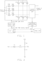
- the overcurrent protection unit comprises an AC side current detection unit, an overcurrent determination unit, the delay unit, and a DSP unit; the output end of the T-type three-level inverter circuit is connected to the AC side current detection unit, the AC side current detection unit is connected to the overcurrent determination unit, the overcurrent determination unit is connected to the delay unit and an IO1 port of the DSP unit, the delay unit is connected to an IO2 port of the DSP unit; the DSP unit is connected to the switch tube driver unit;
- the delay unit is consisted of two resistors, a capacitor, and a diode, an output end of the overcurrent signal is connected to a negative electrode of the diode D1, a positive electrode of the diode D1 is connected to an end of the resistor R1, another end of the resistor R1 is connected to an end of the resistor R2, an end of the capacitor C1 is connected to an output end of the overcurrent delay signal, another end of the resistor R2 is connected to a power source VCC, another end of the capacitor C1 is grounded.
- a size of a delay time of the delay unit is determined by a RC delay link consisting of R1 and C1.
- the overcurrent determination unit is consisted of resistors R3-R7 and comparators U1, U2,
- I_AC_Sample is a current sampling signal of the AC side current detection unit
- ref+ and ref- are an upper limit and a lower limit of overcurrent determination respectively, which are obtained by dividing voltage of VCC through resistors R3, R4, R5, R6, when the current sampling signal is less than the lower limit or greater than the upper limit, the current sampling signal will trigger the comparators U1, U2 to flip over, causing the TZ1 signal to be pulled to a low level.
- the present invention further discloses an overcurrent protection method for T-type three-level inverter, comprising following steps:
- the IO1 receives a low level signal TZ1, setting all the PWM signals of the vertical transistors of the T-type three-level inverter circuit to low, and locking a state
- the IO2 receives a low level signal TZ2, setting all the PWM signals of the horizontal transistors of the T-type three-level inverter circuit to low, and locking a state.
- the DSP unit transmits the instruction to the switch tube driver unit, the switch tube driver unit immediately outputs the instruction to set PWM driving signals of vertical transistors Q1A, Q2A to low, maintains original states of PWM driving signals of Q3A, Q4A, and the current is commutated from the vertical transistor Q1A to the horizontal transistors Q3A, Q4A.
- the DSP unit receives the signal TZ2 becoming low, the DSP unit transmits the instruction to the switch tube driver unit, the switch tube driver unit immediately sets the PWM driving signals of the horizontal transistors Q3A, Q4A output by itself to low, and the current is commutated from the horizontal transistors Q3A, Q4A to an anti-parallel diode of the other vertical transistors Q2A.
- the DSP unit locks the low PWM signals, maintain the low level, and unlock an PWM signal output after detecting that an abnormal recovery condition is met.
- the overcurrent protection device and protection method for T-type three-level inverter have the following advantages: when the overcurrent protection occurs in the T-type three-level inverter, the current is first commutated from the vertical transistors to the horizontal transistors, and after a certain delay, the current is then commutated from the horizontal transistors to the switch tube of another vertical transistor, compared with directly switching off all the switch tubes, the method can effectively reduce the VDS voltage stress of the inverter switch tube and avoid device failure and damage. And the circuit and method only need to add delay unit and DSP configuration in the original common overcurrent protection circuit and method, the method is simple, low cost, and high reliability.
- the overcurrent protection apparatus for T-type three-level inverter of the invention includes a T-type three-level inverter circuit, an overcurrent protection circuit, and a switch tube driver unit.
- An output end of the T-type three-level inverter circuit is connected to the overcurrent protection circuit, the overcurrent protection circuit is connected to the switch tube driver unit, the switch tube driver unit is connected to horizontal transistors and vertical transistors of the T-type three-level inverter circuit.
- the overcurrent protection circuit includes an AC side current detection unit, an overcurrent determination unit, a delay unit, and a DSP unit.
- the output end of the T-type three-level inverter circuit is connected to the AC side current detection unit, the AC side current detection unit is connected to the overcurrent determination unit, the overcurrent determination unit is connected to the delay unit and an IO1 port of the DSP unit, the delay unit is connected to an IO2 port of the DSP unit; the DSP unit is connected to the switch tube driver unit.
- the AC side current detection unit is used to detect an AC side current of the T-type three-level inverter circuit in real time; the overcurrent determination unit is used to determine whether the T-type three-level inverter circuit has overcurrent and output an overcurrent signal; the delay unit is used to perform a delay process to the overcurrent signal and then output an overcurrent delay signal; the DSP unit is used to receive the overcurrent signal and the overcurrent delay signal and transmit a corresponding instruction to the switch tube driver unit according to the signals; the switch tube driver unit can turn off the vertical transistors and the horizontal transistors of the T-type three-level inverter according to the instruction of the DSP unit.
- the AC side current detection unit detects the AC side current in real time, and determines whether overcurrent occurs through the overcurrent determination unit, if overcurrent occurs, the overcurrent determination unit outputs a low level signal TZ1 to a function port IO1 of the DSP unit, meanwhile the delay unit generates a low level signal TZ2 according to the signal TZ1 and outputs same to another function port IO2 of the DSP unit.
- the DSP unit Pre-configuring the DSP, so that when the IO1 of the DSP unit receives the signal TZ1, the DSP unit transmits the instruction to switch tube driver unit to close all the vertical transistors of T-type three-level inverter circuit, when the IO2 of the DSP unit receives the signal TZ2, the DSP unit transmits the instruction to switch tube driver unit to close all the horizontal transistors of T-type three-level inverter circuit.
- the delay unit is consisted of two resistors, a capacitor, and a diode, an output end of the signal TZ1 is connected to a negative electrode of the diode D1, a positive electrode of the diode D1 is connected to an end of the resistor R1, another end of the resistor R1 is connected to an end of the resistor R2, an end of the capacitor C1 is connected to an output end of the signal TZ2, another end of the resistor R2 is connected to a power source VCC, another end of the capacitor C1 is grounded.
- FIG. 3 illustrates a form of the overcurrent determination unit, which is consisted of resistors R3-R7 and comparators U1, U2,
- I_AC_Sample is a current sampling signal of the AC side current detection unit
- ref+ and ref- are an upper limit and a lower limit of overcurrent determination respectively, which are obtained by dividing voltage of the VCC through the resistors R3, R4, R5 and R6.
- the current sampling signal is less than the lower limit or greater than the upper limit, it will trigger the comparators U1, U2 to flip over, causing the signal TZ1 to be pulled to the low level.
- IO1 and IO2 are any two DSP IOs that can be configured with TZ function
- IO1 is configured with the TZ function, which corresponds to all vertical transistor PWM signals of the T-type three-level inverter circuit
- IO2 is configured with the TZ function, which corresponds to all horizontal transistor PWM signals of the T-type three-level inverter circuit
- IO1 receives the low level signal TZ1
- all the PWM signals of the vertical transistors of the T-type three-level inverter circuit are set to low and locked.
- IO2 receives the low level signal TZ2
- all the PWM signals of the horizontal transistors of the T-type three-level inverter circuit are set to low and locked.
- Table 1 DSP configuration mode Configuration function Configuring corresponding PWM signals IO1 TZ-set low PWMQ1A PWMQ2A PWMQ1B PWMQ2B PWMQ1C PWMQ2C IO2 TZ-set low PWMQ3A PWMQ4A PWMQ3B PWMQ4B PWMQ3C PWMQ4C Take A-phase as an example, assuming that the T-type three-level inverter circuit is working in a grid-connected state, the current of the A-phase vertical transistor Q1A overcurrent occurs, so the output signal TZ1 of the overcurrent determination unit is set to low, and the signal TZ1 is received by the IO1 function port of the DSP unit, the DSP unit transmits the instruction to the switch tube driver unit, the switch tube driver unit immediately outputs the instruction to set PWM driving signals of vertical transistors Q1A and Q2A to low, maintains original states of PWM driving signals of Q3A and Q4A, and the current is commutated from the vertical transistor
- the TZ2 When the TZ1 becomes low level, the TZ2 will also be pulled to low level after a fixed delay time of the delay unit, a size of the fixed delay time is determined by a RC delay link consisting of R1 and C1.
- the DSP unit receives the signal TZ2 becoming low, the DSP unit transmits the instruction to the switch tube driver unit, the switch tube driver unit immediately sets the PWM driving signals of the horizontal transistors Q3A and Q4A output by itself to low, and the current is commutated from the horizontal transistors Q3A and Q4A to an anti-parallel diode of the other vertical transistors Q2A.
- the DSP unit will lock the low PWM signals, maintain the low level, and unlock the PWM signal output after it detects that an abnormal recovery condition is met, an abnormal release condition depends on a specific situation of the T-type three-level inverter circuit.
- the output end of the comparator in the overcurrent determination unit is in a high resistance state, the signal TZ1 is pulled to a high level by a pull-up resistor, and the output signal TZ2 of the delay circuit is also pulled to a high level by the pull-up resistor R2, TZ of the DSP unit will not be triggered, the DSP unit normally controls its PWM driving signal according to the working state of the T-type three-level inverter circuit.
Landscapes
- Engineering & Computer Science (AREA)
- Power Engineering (AREA)
- Inverter Devices (AREA)
Applications Claiming Priority (2)
| Application Number | Priority Date | Filing Date | Title |
|---|---|---|---|
| CN202210201802.3A CN114583658A (zh) | 2022-03-03 | 2022-03-03 | 一种t型三电平逆变器的过流保护装置及保护方法 |
| PCT/CN2022/098117 WO2023165047A1 (zh) | 2022-03-03 | 2022-06-10 | 一种t型三电平逆变器的过流保护装置及保护方法 |
Publications (2)
| Publication Number | Publication Date |
|---|---|
| EP4489288A1 true EP4489288A1 (de) | 2025-01-08 |
| EP4489288A4 EP4489288A4 (de) | 2026-03-11 |
Family
ID=81772259
Family Applications (1)
| Application Number | Title | Priority Date | Filing Date |
|---|---|---|---|
| EP22929482.2A Pending EP4489288A4 (de) | 2022-03-03 | 2022-06-10 | Überstromschutzvorrichtung und schutzverfahren für einen dreistufigen t-wechselrichter |
Country Status (4)
| Country | Link |
|---|---|
| US (1) | US20250174978A1 (de) |
| EP (1) | EP4489288A4 (de) |
| CN (1) | CN114583658A (de) |
| WO (1) | WO2023165047A1 (de) |
Families Citing this family (2)
| Publication number | Priority date | Publication date | Assignee | Title |
|---|---|---|---|---|
| CN114583658A (zh) * | 2022-03-03 | 2022-06-03 | 浙江艾罗网络能源技术股份有限公司 | 一种t型三电平逆变器的过流保护装置及保护方法 |
| CN120110198B (zh) * | 2025-05-08 | 2025-08-15 | 锦浪科技股份有限公司 | 一种t型三电平电路故障封波恢复处理方法 |
Family Cites Families (9)
| Publication number | Priority date | Publication date | Assignee | Title |
|---|---|---|---|---|
| JP5179954B2 (ja) * | 2008-06-03 | 2013-04-10 | 株式会社日立製作所 | 半導体スイッチング素子用ゲート駆動装置を備えた電力変換装置 |
| CN203151454U (zh) * | 2013-01-21 | 2013-08-21 | 东莞联洲电子科技有限公司 | 车载acc延迟关机电路 |
| CN104377659B (zh) * | 2013-08-16 | 2018-01-02 | 力博特公司 | 封波‑解封波方法和装置、解封波方法和装置及逆变电路 |
| CN103944148A (zh) * | 2014-04-17 | 2014-07-23 | 华为技术有限公司 | 一种t型三电平逆变器的保护方法、装置及逆变电路 |
| CN209913489U (zh) * | 2019-07-02 | 2020-01-07 | 深圳市智创电机有限公司 | 逐波限流电路 |
| CN110581643B (zh) * | 2019-09-17 | 2022-09-30 | 广东希塔变频技术有限公司 | 三相pfc电路、电机驱动电路和设备 |
| CN110739873B (zh) * | 2019-09-24 | 2020-08-11 | 科华恒盛股份有限公司 | 三电平逐波限流电路和控制方法 |
| CN114024436B (zh) * | 2022-01-10 | 2022-03-22 | 浙江日风电气股份有限公司 | 一种t型三电平关机控制方法、装置及系统 |
| CN114583658A (zh) * | 2022-03-03 | 2022-06-03 | 浙江艾罗网络能源技术股份有限公司 | 一种t型三电平逆变器的过流保护装置及保护方法 |
-
2022
- 2022-03-03 CN CN202210201802.3A patent/CN114583658A/zh active Pending
- 2022-06-10 WO PCT/CN2022/098117 patent/WO2023165047A1/zh not_active Ceased
- 2022-06-10 US US18/843,445 patent/US20250174978A1/en active Pending
- 2022-06-10 EP EP22929482.2A patent/EP4489288A4/de active Pending
Also Published As
| Publication number | Publication date |
|---|---|
| WO2023165047A1 (zh) | 2023-09-07 |
| EP4489288A4 (de) | 2026-03-11 |
| CN114583658A (zh) | 2022-06-03 |
| US20250174978A1 (en) | 2025-05-29 |
Similar Documents
| Publication | Publication Date | Title |
|---|---|---|
| KR101924707B1 (ko) | 전압원 멀티 레벨 컨버터, 직류 전력 전송 시스템 및 고장 처리 방법 및 디바이스 | |
| US20240136817A1 (en) | Photovoltaic quick turn-off system and control method therefor | |
| JP5730456B1 (ja) | 電力変換装置 | |
| EP4489288A1 (de) | Überstromschutzvorrichtung und schutzverfahren für einen dreistufigen t-wechselrichter | |
| US11316443B2 (en) | Control of active neutral-point clamped three-level converter | |
| CN201766490U (zh) | 基于igbt桥式开关拓扑的驱动电路及其保护模块 | |
| CN110474622B (zh) | 一种自锁保护电路及空调器 | |
| CN103944148A (zh) | 一种t型三电平逆变器的保护方法、装置及逆变电路 | |
| WO2009120851A2 (en) | Method and apparatus for resetting silicon controlled rectifiers in a hybrid bridge | |
| CN105391032B (zh) | 一种混合背靠背直流输电装置及故障处理方法 | |
| CN104638615A (zh) | 具有直流故障隔离能力的模块化多电平换流器及其子模块 | |
| TW201338322A (zh) | 發電系統及其開關裝置 | |
| WO2021179858A1 (zh) | 绝缘栅极双极型晶体管的保护装置和方法 | |
| GB2564700A (en) | A power electronics module and a method of detecting a fault in a power electronics module | |
| CN102097789A (zh) | 一种igbt过流或短路状态检测电路 | |
| CN119362361A (zh) | 保护电路、控制方法及光伏系统 | |
| JP3808326B2 (ja) | 電力変換装置 | |
| CN117791511A (zh) | 一种功率变换器及其直流侧对地短路的保护方法 | |
| CN112379153B (zh) | 一种直流振荡检测电路、直流电弧检测电路及逆变器 | |
| WO2016170672A1 (ja) | 電力変換装置 | |
| CN214314559U (zh) | 一种pfc过流检测及保护电路及空调器 | |
| CN211209312U (zh) | 回馈器装置 | |
| CN213547389U (zh) | 一种用于抑制电网能量倒灌的储能变流器 | |
| JP2001037244A (ja) | 電力変換装置 | |
| CN111082456A (zh) | 回馈器装置及控制方法 |
Legal Events
| Date | Code | Title | Description |
|---|---|---|---|
| STAA | Information on the status of an ep patent application or granted ep patent |
Free format text: STATUS: THE INTERNATIONAL PUBLICATION HAS BEEN MADE |
|
| PUAI | Public reference made under article 153(3) epc to a published international application that has entered the european phase |
Free format text: ORIGINAL CODE: 0009012 |
|
| STAA | Information on the status of an ep patent application or granted ep patent |
Free format text: STATUS: REQUEST FOR EXAMINATION WAS MADE |
|
| 17P | Request for examination filed |
Effective date: 20240926 |
|
| AK | Designated contracting states |
Kind code of ref document: A1 Designated state(s): AL AT BE BG CH CY CZ DE DK EE ES FI FR GB GR HR HU IE IS IT LI LT LU LV MC MK MT NL NO PL PT RO RS SE SI SK SM TR |
|
| DAV | Request for validation of the european patent (deleted) | ||
| DAX | Request for extension of the european patent (deleted) | ||
| REG | Reference to a national code |
Ref country code: DE Ref legal event code: R079 Free format text: PREVIOUS MAIN CLASS: H02M0007537000 Ipc: H02M0001320000 |
|
| A4 | Supplementary search report drawn up and despatched |
Effective date: 20260206 |
|
| RIC1 | Information provided on ipc code assigned before grant |
Ipc: H02M 1/32 20070101AFI20260202BHEP Ipc: H02M 7/487 20070101ALI20260202BHEP Ipc: H02H 3/093 20060101ALI20260202BHEP Ipc: H02M 1/00 20060101ALN20260202BHEP Ipc: H02M 1/36 20070101ALN20260202BHEP |