EP4487989A1 - Systeme und verfahren zur reparatur mittels ultraschall - Google Patents
Systeme und verfahren zur reparatur mittels ultraschall Download PDFInfo
- Publication number
- EP4487989A1 EP4487989A1 EP24182858.1A EP24182858A EP4487989A1 EP 4487989 A1 EP4487989 A1 EP 4487989A1 EP 24182858 A EP24182858 A EP 24182858A EP 4487989 A1 EP4487989 A1 EP 4487989A1
- Authority
- EP
- European Patent Office
- Prior art keywords
- tool
- repair
- welding
- machining
- repair tool
- Prior art date
- Legal status (The legal status is an assumption and is not a legal conclusion. Google has not performed a legal analysis and makes no representation as to the accuracy of the status listed.)
- Pending
Links
Images


Classifications
-
- B—PERFORMING OPERATIONS; TRANSPORTING
- B23—MACHINE TOOLS; METAL-WORKING NOT OTHERWISE PROVIDED FOR
- B23P—METAL-WORKING NOT OTHERWISE PROVIDED FOR; COMBINED OPERATIONS; UNIVERSAL MACHINE TOOLS
- B23P6/00—Restoring or reconditioning objects
-
- B—PERFORMING OPERATIONS; TRANSPORTING
- B23—MACHINE TOOLS; METAL-WORKING NOT OTHERWISE PROVIDED FOR
- B23K—SOLDERING OR UNSOLDERING; WELDING; CLADDING OR PLATING BY SOLDERING OR WELDING; CUTTING BY APPLYING HEAT LOCALLY, e.g. FLAME CUTTING; WORKING BY LASER BEAM
- B23K20/00—Non-electric welding by applying impact or other pressure, with or without the application of heat, e.g. cladding or plating
- B23K20/10—Non-electric welding by applying impact or other pressure, with or without the application of heat, e.g. cladding or plating making use of vibrations, e.g. ultrasonic welding
-
- B—PERFORMING OPERATIONS; TRANSPORTING
- B23—MACHINE TOOLS; METAL-WORKING NOT OTHERWISE PROVIDED FOR
- B23K—SOLDERING OR UNSOLDERING; WELDING; CLADDING OR PLATING BY SOLDERING OR WELDING; CUTTING BY APPLYING HEAT LOCALLY, e.g. FLAME CUTTING; WORKING BY LASER BEAM
- B23K20/00—Non-electric welding by applying impact or other pressure, with or without the application of heat, e.g. cladding or plating
- B23K20/26—Auxiliary equipment
-
- B—PERFORMING OPERATIONS; TRANSPORTING
- B23—MACHINE TOOLS; METAL-WORKING NOT OTHERWISE PROVIDED FOR
- B23P—METAL-WORKING NOT OTHERWISE PROVIDED FOR; COMBINED OPERATIONS; UNIVERSAL MACHINE TOOLS
- B23P15/00—Making specific metal objects by operations not covered by a single other subclass or a group in this subclass
-
- B—PERFORMING OPERATIONS; TRANSPORTING
- B23—MACHINE TOOLS; METAL-WORKING NOT OTHERWISE PROVIDED FOR
- B23P—METAL-WORKING NOT OTHERWISE PROVIDED FOR; COMBINED OPERATIONS; UNIVERSAL MACHINE TOOLS
- B23P23/00—Machines or arrangements of machines for performing specified combinations of different metal-working operations not covered by a single other subclass
- B23P23/04—Machines or arrangements of machines for performing specified combinations of different metal-working operations not covered by a single other subclass for both machining and other metal-working operations
-
- B—PERFORMING OPERATIONS; TRANSPORTING
- B23—MACHINE TOOLS; METAL-WORKING NOT OTHERWISE PROVIDED FOR
- B23P—METAL-WORKING NOT OTHERWISE PROVIDED FOR; COMBINED OPERATIONS; UNIVERSAL MACHINE TOOLS
- B23P2700/00—Indexing scheme relating to the articles being treated, e.g. manufactured, repaired, assembled, connected or other operations covered in the subgroups
- B23P2700/01—Aircraft parts
-
- B—PERFORMING OPERATIONS; TRANSPORTING
- B23—MACHINE TOOLS; METAL-WORKING NOT OTHERWISE PROVIDED FOR
- B23P—METAL-WORKING NOT OTHERWISE PROVIDED FOR; COMBINED OPERATIONS; UNIVERSAL MACHINE TOOLS
- B23P6/00—Restoring or reconditioning objects
- B23P6/002—Repairing turbine components, e.g. moving or stationary blades, rotors
- B23P6/005—Repairing turbine components, e.g. moving or stationary blades, rotors using only replacement pieces of a particular form
-
- B—PERFORMING OPERATIONS; TRANSPORTING
- B64—AIRCRAFT; AVIATION; COSMONAUTICS
- B64F—GROUND OR AIRCRAFT-CARRIER-DECK INSTALLATIONS SPECIALLY ADAPTED FOR USE IN CONNECTION WITH AIRCRAFT; DESIGNING, MANUFACTURING, ASSEMBLING, CLEANING, MAINTAINING OR REPAIRING AIRCRAFT, NOT OTHERWISE PROVIDED FOR; HANDLING, TRANSPORTING, TESTING OR INSPECTING AIRCRAFT COMPONENTS, NOT OTHERWISE PROVIDED FOR
- B64F5/00—Designing, manufacturing, assembling, cleaning, maintaining or repairing aircraft, not otherwise provided for; Handling, transporting, testing or inspecting aircraft components, not otherwise provided for
- B64F5/40—Maintaining or repairing aircraft
Definitions
- the present disclosure relates to systems and methods for repair and more particularly to systems and methods for ultrasonic repair.
- a method includes installing a welding tool into a repair tool holder, ultrasonic welding a repair sheet to a part to be repaired with the welding tool, removing the welding tool from the repair tool holder, installing a machining tool into the repair tool holder, and ultrasonic machining a portion of the repair sheet that is welded to the part to be repaired to match an a predetermined geometry of the part to be repaired with the machining tool.
- the method can further include installing a repair tool adapter into the repair tool, the repair tool adapter configured for both axial movement and rotational movement when installed in the repair tool holder.
- Installing the welding tool into the repair tool holder can include installing a welding tool tip into the repair tool adapter and installing the machining tool into the repair tool holder can include installing a machining tool tip into the repair tool adapter and installing the repair tool adapter to the repair tool holder.
- the method can include, after installing the welding tool into the repair tool adapter, aligning the welding tool tip relative to the part to be repaired based on a predetermined offset for the welding tool tip.
- the method can include, after installing the machining tool into the repair tool adapter, aligning the machining tool tip relative to the part to be repaired based on a predetermined offset for the machining tool tip.
- the predetermined offset for the welding tool tip and predetermined offset for the machining tool tip can be the same or in embodiments, the predetermined offset for the welding tool tip and predetermined offset for the machining tool tip can be different.
- the predetermined offset for the repair tool head can be based on a type of repair tool head or another parameter of the repair tool head.
- aligning the weld tool tip can include, using an alignment system (e.g., an interferometer or a touch probe), measuring the relative position of the weld tool tip to the part to be repaired and comparing the measured relative position to the predetermined offset for the welding tool.
- aligning the machining tool tip can include, using the alignment system, measuring the relative position of the machining tool tip to the part to be repaired and comparing the measured relative position to the predetermined offset for the machining tool.
- the method can be performed automatically, e.g., at least, installing the respective tools, removing/changing the respective tools, ultrasonic welding and ultrasonic machining.
- repair system can include a repair tool, a repair tool adapter operatively interfaced with the repair tool, and a plurality of differing tool heads configured to be inserted into the repair tool adapter such that the repair tool is configured for both ultrasonic welding and ultrasonic machining.
- the system can include one or more ultrasonic transducers disposed in the repair tool configured to convert ultrasonic vibration to heat energy and/or cutting energy such that the tool is configured for both ultrasonic welding and ultrasonic machining.
- the repair tool can also include a holding portion configured to be inserted into or grasped by a motive system to move the repair tool over a part to be repaired.
- the repair system can include the motive system and in certain embodiments, the motive system includes a gantry.
- the gantry can be part of a CNC machine.
- the system can include an optical interferometer in optical communication with the repair tool configured to inspect and measure a position of the repair tool head relative to a part to be repaired.
- the system can include a controller and the controller can be configured to compare the measured relative position of the repair too head to a predetermined offset for the repair tool head.
- the controller can be configured to control the motive system to reposition the repair tool head relative to the part to be repaired based at least in part on the measurement data comparison.
- the predetermined offset for the repair tool head can be based on a type of repair tool head or another parameter of the repair tool head.
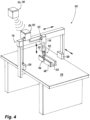
- Fig. 1 an illustrative view of an embodiment of a system in accordance with the disclosure is shown in Fig. 1 and is designated generally by reference character 100.
- Other embodiments and/or aspects of this disclosure are shown in Figs. 2-8 .
- Certain embodiments can be used to repair parts in very small or complex/hard to reach locations where a conventional repair tool would be unable to reach, for example as discussed herein below with respect to Figs. 6-8B .
- Embodiments also allow for repairs without complete disassembly of the part to be repaired.
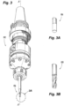
- repair system 100 can include a repair tool 102, a repair tool adapter 104 operatively interfaced with the repair tool 102, and a plurality of differing tool heads 106, 108 configured to be inserted into the repair tool adapter 104 such that the repair tool is configured for both ultrasonic welding and ultrasonic machining.
- the repair tool adapter 104 can include a collet configured to act similar to a chuck to accept the one or more differing repair tool heads 106, 108 within the same adapter 104, and without requiring a change of the repair tool 102 as a whole.
- the collet 104 is also configured to allow longitudinal, axial motion of a welding tool head 106 during ultrasonic welding, and rotation of a machining tool head 108 during ultrasonic machining.
- One or more ultrasonic transducers 110 can be disposed in the repair tool 102 configured to convert ultrasonic vibration to heat energy (e.g., for ultrasonic welding) and/or cutting energy (e.g., for ultrasonic machining) such that the repair tool is configured for both ultrasonic welding and ultrasonic machining.
- a horn 112 can be included configured to focus the ultrasonic vibration from the transducers to the tool head 106, 108.
- the repair tool 102 can also include a holding portion 114 configured to be inserted into or grasped by a motive system 116 to move the repair tool 102 over bed 118 having a part to be repaired 120.
- the system 100 can include the motive system 116, and the motive system 116 can include a grabbing portion 122 configured to grab the holding portion 114 of the repair tool 102.
- the motive system 116 includes a gantry 124.
- the repair system 100 can include a CNC machine, and the gantry 124 can be part of the CNC machine.
- the holding portion 114 of the repair tool 102 can be formed or designed to fit a general CNC machine, or can be formed or designed to fit a particular CNC machine model. In certain embodiments, the holding portion 114 of the repair tool 102 can be formed or designed to fit another type of repair system, such as an HSK solid tool holding system, a CAT tapered tool holder, or a BT tool holder, for example.
- the system 100 can also include a controller 126, e.g., for controlling the motive system 116.
- the controller 126 can be or include a CNC controller configured to control the motive system 116 to move the repair tool 102 on the gantry 118 over the part to be repaired 120 and to perform the necessary repair functions, e.g., the welding and machining.
- the controller 126 can be configured to move the motive system 116 in 5 axes.
- the controller 126 can be programmed by a number of user inputs, such as the type and size of the part to be repaired 120, the material of the part to be repaired 120, a desired pressure and speed or frequency of the tool 106, 108 based on the material, and/or tool size, among others.
- the system 100 can include an alignment system 128.
- the alignment system can be an optical interferometer in optical communication with the repair tool 102 configured to inspect and measure a position of the repair tool head 106, 108 relative to a part to be repaired 120.
- the alignment system can include a touch probe system, which can be similarly employed as the interferometer to inspect and measure the position of the repair tool head.
- a controller 130 e.g., together with or separate from controller 126) can be configured to compare the measured relative position of the repair too head 106, 108 to a predetermined offset (e.g., axial and radial) for the repair tool head.
- the axial and radial offset refers to a distance between the tool 102 and the part to be repaired 120 in both the axial and radial directions, along the tool to the spindle interface.
- the offset can also include an angular offset, the angle of the tool head 106, 108 oriented relative to the part to be repaired 120.
- the optical interferometer system 128 can include an optical transmitter 132 (e.g., a laser transmitter) configured to transmit an optical beam 134, and an optical receiver 136 positioned opposite from the transmitter 132 configured to receive the optical beam 134.
- One or more optical elements 138 can be posited between the optical transmitter 132 and optical receiver 136 configured to modify the transmitted beam 134 such that a focal point 140 of the beam 134 is at the tool head 106, 108.
- the controller 126, 130 can be configured to control the motive system 116 to reposition the repair tool 102 and/or the repair tool head 106, 108 relative to the part to be repaired 120 based at least in part on the measurement data comparison, for example, if the measured offset does not match the predetermined offset after changing the tool head 106, 108.
- the predetermined offset for the repair tool head 106, 108 can be based on a type of repair tool head or another parameter of the repair tool head.
- the parameters can include, among others, the type of repair tool head (e.g., welding or machining), the size of the repair tool head and/or a manufacturer of the repair tool head.
- Each of these parameters may affect the offset from the part to be repaired as different manufacturers may have different shapes or orientations of the same tool heads, for example. Aligning the tool head each time based on these parameters allows the system 100 to accept a wide variety of tool heads including many tool types and tool heads from different suppliers. In some cases, the offset between the welding and machining tool head may be the same.
- a method (e.g., a method of repairing a part) can include installing a repair tool adapter (e.g., adapter 104) into a repair tool (e.g., tool 102), the repair tool adapter configured to allow both axial movement and rotational movement of a repair tool head (e.g., tool head 106, 108) when installed in the repair tool holder.
- a repair tool adapter e.g., adapter 104
- a repair tool e.g., tool 102
- the repair tool adapter configured to allow both axial movement and rotational movement of a repair tool head (e.g., tool head 106, 108) when installed in the repair tool holder.
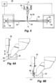
- the method can further include installing a welding tool (e.g., tool head 106) into the repair tool adapter, ultrasonic welding a repair sheet 142 to a part to be repaired with the welding tool (e.g., as shown in Figs. 6A , 7A, 8A ), removing the welding tool from the repair tool adapter, installing a machining tool (e.g., tool head 108) into the repair tool adapter, and ultrasonic machining the portion of the repair sheet that is welded to the part to be repaired to match a predetermined geometry of the part to be repaired with the machining tool (e.g., as shown in 6B, 7B, 8B).
- a welding tool e.g., tool head 106
- a machining tool e.g., tool head 108
- the repair sheet 142 can include sheet metal, for example, or any other suitable material that matches or is compatible with a base material of a part to be repaired.
- the repair sheet can be sheet metal.
- Figs. 6A-8B show embodiments of a method for repairing an outside engine casing or flange ( Fig. 6A, 6B ), an inner side engine casing or flange ( Fig. 7A, 7B ), and detailed tooling ( Fig. 8A, 8B ).
- the method can include, after installing the welding tool into the repair tool adapter, aligning the welding tool tip relative to the part to be repaired based on a predetermined offset for the welding tool tip.
- the method can include, after installing the machining tool into the repair tool adapter, aligning the machining tool tip relative to the part to be repaired based on a predetermined offset for the machining tool tip.
- the predetermined offset for the welding tool tip and predetermined offset for the machining tool tip can be the same or in embodiments, the predetermined offset for the welding tool tip and predetermined offset for the machining tool tip can be different based on one or more repair tool parameters (e.g., as discussed above with respect to system 100).
- aligning the weld tool tip can include, using an interferometer (e.g., interferometer system 128), measuring the relative position of the weld tool tip to the part to be repaired and comparing the measured relative position to the predetermined offset for the welding tool.
- aligning the machining tool tip can include, using the interferometer, measuring the relative position of the machining tool tip to the part to be repaired and comparing the measured relative position to the predetermined offset for the machining tool.
- the method can be performed automatically.
- the repair tool holder is installed into the motive system (e.g., motive system 116) and the controller (e.g., controller 126, 130) is programmed as needed for the given application, installing the respective tool heads, removing/changing the respective tool heads, ultrasonic welding, and ultrasonic machining can all be performed automatically by the system, and without further user input.
- the motive system e.g., motive system 116
- the controller e.g., controller 126, 130
- MRO maintenance, repair and overhaul
- the current typical repair workflow for a worn/damaged metal component can include scanning and analysis, repair process by deposition, real time monitoring and machining, which are typically performed at different machines to obtain a good form accuracy and surface finish.
- these processes are well established individually, few solutions to repair parts with limited working envelope or very small clearance for tools, such as engine casing/flange or in between turbine blades, are available.
- the absence of a fully integrated and automatic repair solution represents a significant challenge for reducing adoption barriers such as repair versatility, capital investment, time to deploy, safety, and data flow management.
- Embodiments of the systems and methods described herein therefore offer a solution to these concerns by providing for an automatic repair process, bringing together the ultrasonic welding and ultrasonic machining during the repair process.
- Ultrasonic welding is a joining process including using high frequency ultrasonic vibrations (e.g., about 20-40 kHz) to convert electrical energy into heat.
- This process can be used to join plastics as well as most of metals, where high frequency vibrations together with pressure applied can join two materials quickly and securely, without the need of large amounts of heat as in traditional welding process.
- Using ultrasonic vibration as described herein can provide a number of advantages over conventional processes, including lower energy consumption and reduced process cost.
- the ultrasonic energy for welding can be used for thermal softening, and experimental results reveal that the ultrasonic energy required to produce an identical amount of softening is much less than the required thermal energy.
- Ultrasonic welding can also eliminate subjective elements in the welding process, ensuring consistent quality and can allow for quick and easy setup, e.g., when moving from one set up to another, for example.
- Figs. 1 and 2 show an embodiment of an ultrasonic tooling system with at least three components: transducer(s) 110, a horn 112, and tool head 106, 108.
- the electrical energy input to the transducer is converted to mechanical vibrations along its longitudinal axis A at high frequency (e.g., about at 20-40 kHz).
- the excited vibration is subsequently transmitted through an energy-focusing horn to amplify the vibration amplitude and finally delivered to the tool tip.
- the tool which is placed directly above the workpiece during a repair, can vibrate along its longitudinal axis with a desired amplitude.
- Embodiments described in this disclosure include a method to improve the repair efficiency and attain accurate shapes by using multi-step ultrasonic process.
- First the ultrasonic welding process can be used to weld a repair sheet (e.g., a metal sheet in the case of aero engines) to the area to be repaired as one intermediate feature. Once the repaired areas are welded, the workpiece can then be finished with ultrasonic machining in the same setup as the ultrasonic welding too, but switching the tool head for an ultrasonic machining tooling.
- a common design for the repair tool is needed to leverage the capabilities of the two techniques for single feature to create the intermediate shape and to then use ultrasonic machining to finish the feature.
- the repair tool can include a collet (e.g., an ER-32 collet) for holding the tool hear and a common tool holder (e.g., a CAT tapered tool holder) as shown in Fig. 1 .
- a collet e.g., an ER-32 collet
- a common tool holder e.g., a CAT tapered tool holder
- the respective tools and tool heads can be additively manufactured to create unique tool geometries selected tool materials.
- the tool length can be measured with the on-machine tool measurement system (e.g., the interferometer system described above) as shown in Fig. 5 to get the tool diameter and length offset for each tool assembly.
- Welded strength is largely affected by the magnitude of the welding energy and required duration. Welding energy required for welding decreases as welding pressure increases, typically welding pressure for metals varies from about 5 to about 60 MPa (or 80 - 960 N for a pressurizing area of 16 mm 2 ). With the increase of welding pressure, required energy and duration can be shortened.
- vibration frequency can be determined by the tooling design, for example tool length. Once the tooling design is selected, the vibration frequency is fixed, thus the main parameter to optimize is the vibration amplitude. With the increase of vibration amplitude, welding energy increases, which also shortens welding duration or fast feed rates for welding.
- Benefits of multistep ultrasonic system and methods for repair as disclosed herein include improving the process efficiency, shortening cycle time and avoiding part transfer when switching between the different processes. Embodiments allow for accurate positioning of the tooling for both processes. Additionally, the loads for both ultrasonic welding and machining are significantly smaller than traditional friction stir welding and high-speed milling, respectively, which helps to reduce part deformation during repair process to keep the geometries within tolerance.
- aspects of the present disclosure may be embodied as a system, method or computer program product. Accordingly, aspects of this disclosure may take the form of an entirely hardware embodiment, an entirely software embodiment (including firmware, resident software, micro-code, etc.), or an embodiment combining software and hardware aspects, all possibilities of which can be referred to herein as a "circuit,” “module,” or “controller.”
- a “circuit,” “module,” or “controller” can include one or more portions of one or more separate physical hardware and/or software components that can together perform the disclosed function of the "circuit,” “module,” or “controller”, or a “circuit,” “module,” or “controller” can be a single self-contained unit (e.g., of hardware and/or software).
- aspects of this disclosure may take the form of a computer program product embodied in one or more computer readable medium(s) having computer readable program code embodied thereon.
- any numerical values disclosed herein can be exact values or can be values within a range. Further, any terms of approximation (e.g., “about”, “approximately”, “around”) used in this disclosure can mean the stated value within a range. For example, in certain embodiments, the range can be within (plus or minus) 20%, or within 10%, or within 5%, or within 2%, or within any other suitable percentage or number as appreciated by those having ordinary skill in the art (e.g., for known tolerance limits or error ranges).
- a reference to "A and/or B", when used in conjunction with open-ended language such as “comprising” can refer, in one embodiment, to A only (optionally including elements other than B); in another embodiment, to B only (optionally including elements other than A); in yet another embodiment, to both A and B (optionally including other elements); etc.
Landscapes
- Engineering & Computer Science (AREA)
- Mechanical Engineering (AREA)
- Pressure Welding/Diffusion-Bonding (AREA)
- Automatic Tool Replacement In Machine Tools (AREA)
Applications Claiming Priority (1)
| Application Number | Priority Date | Filing Date | Title |
|---|---|---|---|
| US18/213,600 US12343811B2 (en) | 2023-06-23 | 2023-06-23 | Systems and methods for ultrasonic repair |
Publications (1)
| Publication Number | Publication Date |
|---|---|
| EP4487989A1 true EP4487989A1 (de) | 2025-01-08 |
Family
ID=91585679
Family Applications (1)
| Application Number | Title | Priority Date | Filing Date |
|---|---|---|---|
| EP24182858.1A Pending EP4487989A1 (de) | 2023-06-23 | 2024-06-18 | Systeme und verfahren zur reparatur mittels ultraschall |
Country Status (2)
| Country | Link |
|---|---|
| US (1) | US12343811B2 (de) |
| EP (1) | EP4487989A1 (de) |
Citations (3)
| Publication number | Priority date | Publication date | Assignee | Title |
|---|---|---|---|---|
| JPH1044242A (ja) * | 1996-08-06 | 1998-02-17 | Denso Corp | 超音波加工システム |
| US9446475B2 (en) * | 2014-04-09 | 2016-09-20 | Fabrisonic, Llc | Weld assembly for ultrasonic additive manufacturing applications |
| US20200086424A1 (en) * | 2017-03-22 | 2020-03-19 | Hybrid Manufacturing Technologies Limited | A machine tool |
Family Cites Families (36)
| Publication number | Priority date | Publication date | Assignee | Title |
|---|---|---|---|---|
| US4870743A (en) * | 1987-10-13 | 1989-10-03 | Extrude Hone Corporation | Quick change tool assembly for ultrasonic machine tool |
| US4902177A (en) * | 1988-10-27 | 1990-02-20 | Terry K. Aitkens | Rapid change tool cutter and driving system |
| US5079070A (en) * | 1990-10-11 | 1992-01-07 | International Business Machines Corporation | Repair of open defects in thin film conductors |
| RU1245U1 (ru) * | 1992-12-30 | 1995-12-16 | Виктор Михайлович Гусев | Универсальный патрон для автоматизированного крепления инструмента в шпинделе станка |
| JPH0952185A (ja) * | 1995-08-14 | 1997-02-25 | Yazaki Corp | 超音波溶着機 |
| JP3215084B2 (ja) * | 1998-04-28 | 2001-10-02 | 株式会社アルテクス | 超音波振動接合用共振器 |
| US6280125B1 (en) * | 1998-08-15 | 2001-08-28 | Marc H Boisvert | R-8 collet |
| US6932876B1 (en) * | 1998-09-03 | 2005-08-23 | U.I.T., L.L.C. | Ultrasonic impact machining of body surfaces to correct defects and strengthen work surfaces |
| DE10225588B4 (de) * | 2002-06-07 | 2005-03-31 | Sonotronic Nagel Gmbh | Ultraschallschweißanlage |
| DE20208872U1 (de) * | 2002-06-07 | 2002-10-24 | Sonotronic Nagel GmbH, 76307 Karlsbad | Ultraschallschweißanlage |
| JP3983609B2 (ja) | 2002-06-24 | 2007-09-26 | 松下電器産業株式会社 | 部品実装ツールとそれによる部品実装方法および装置 |
| DE102004014944A1 (de) * | 2004-03-26 | 2005-10-13 | Doka Industrie Gmbh | Schalungsbauteil |
| JP2008279692A (ja) * | 2007-05-11 | 2008-11-20 | Toyo Unso Kk | パレットの補修方法 |
| GB0723666D0 (en) | 2007-12-04 | 2008-01-16 | Rolls Royce Plc | Electrical discharge machining |
| US9878377B2 (en) | 2010-03-11 | 2018-01-30 | Edison Industrial Innovation, Llc | High-speed rotary electrical connector for use in ultrasonically assisted machining |
| DE102011006932B4 (de) | 2011-04-07 | 2014-05-28 | Widmann Maschinen GmbH & Co. KG | Vorrichtung zum Schweißen und/oder Schneiden von Werkstücken |
| DE102012215036A1 (de) * | 2012-04-13 | 2013-10-17 | Gühring Ohg | Hydrodehnspannfutter |
| US9366140B2 (en) * | 2013-03-15 | 2016-06-14 | Rolls-Royce Corporation | Ceramic matrix composite repair by reactive processing and mechanical interlocking |
| US10189206B2 (en) * | 2013-09-06 | 2019-01-29 | GM Global Technology Operations LLC | Apparatus and methods for repairing discrepant welds |
| US9658612B2 (en) * | 2013-12-13 | 2017-05-23 | GM Global Technology Operations LLC | Automatic monitoring of the alignment and wear of vibration welding equipment |
| GB2548801B (en) * | 2016-03-21 | 2020-12-02 | Loop Tech Ltd | A system for machining a surface |
| US11220018B2 (en) * | 2018-02-24 | 2022-01-11 | Dalian University Of Technology | Ultrasonic cutting holder for honeycomb core |
| US11205634B2 (en) * | 2018-07-16 | 2021-12-21 | Asm Technology Singapore Pte Ltd | Bonding apparatus with replaceable bonding tool |
| CN108772621A (zh) * | 2018-08-01 | 2018-11-09 | 苏州凯尔博精密机械有限公司 | 一种z轴旋转换刀的超声波焊接枪 |
| WO2020082085A1 (en) * | 2018-10-19 | 2020-04-23 | Arris Composites Inc. | Method and system for creating three-dimensional preforms for use in composite parts |
| CN109848493B (zh) | 2019-01-30 | 2021-01-01 | 上海交通大学 | 一种基于放电加工的多功能集成制造系统 |
| DE102019107539A1 (de) * | 2019-03-25 | 2020-10-01 | Weber Ultrasonics AG | Gestell für eine Bearbeitungsmaschine und Verfahren zum Bearbeiten eines Werkstücks mit derselben |
| CN113245686A (zh) * | 2020-02-11 | 2021-08-13 | 广州市科普超声电子技术有限公司 | 一种多功能超声工具头 |
| CN111468816A (zh) * | 2020-05-25 | 2020-07-31 | 常青智能科技(天津)有限公司 | 一种自动化超声波柔性焊接系统 |
| US11498285B2 (en) * | 2020-09-30 | 2022-11-15 | Ford Global Technologies, Llc | Agile robotic headlamp assembly with sonic fastening and injected lens adhesive |
| CN112222596A (zh) * | 2020-10-20 | 2021-01-15 | 天津市捷威动力工业有限公司 | 一种软包锂电池极耳的超声波焊接方法 |
| CN112809159A (zh) * | 2021-01-21 | 2021-05-18 | 长春富维安道拓汽车饰件系统有限公司 | 一种集成式双超声波焊接单元 |
| CN115091022B (zh) * | 2022-07-06 | 2023-12-05 | 重庆理工大学 | 一种基于搅拌摩擦焊的裂纹修复及微增材方法 |
| CN115781181A (zh) * | 2022-09-19 | 2023-03-14 | 江苏星业精密滚子科技有限公司 | 一种五轴五联动铣磨一体加工滚子球基面的方法 |
| WO2024107232A1 (en) * | 2022-11-18 | 2024-05-23 | Gary Lee Ward | Concentrated longitudinal acoustical/ultrasonic energy fastener design and manipulation system having at least one or a plurality of flexible ultrasonic joints |
| US20240217192A1 (en) * | 2023-01-03 | 2024-07-04 | Rohr, Inc. | Method of repairing thermoplastic composite components with manual ultrasonic weld |
-
2023
- 2023-06-23 US US18/213,600 patent/US12343811B2/en active Active
-
2024
- 2024-06-18 EP EP24182858.1A patent/EP4487989A1/de active Pending
Patent Citations (3)
| Publication number | Priority date | Publication date | Assignee | Title |
|---|---|---|---|---|
| JPH1044242A (ja) * | 1996-08-06 | 1998-02-17 | Denso Corp | 超音波加工システム |
| US9446475B2 (en) * | 2014-04-09 | 2016-09-20 | Fabrisonic, Llc | Weld assembly for ultrasonic additive manufacturing applications |
| US20200086424A1 (en) * | 2017-03-22 | 2020-03-19 | Hybrid Manufacturing Technologies Limited | A machine tool |
Non-Patent Citations (1)
| Title |
|---|
| NADIMPALLI VENKATA KARTHIK ET AL: "Monitoring and repair of defects in ultrasonic additive manufacturing", THE INTERNATIONAL JOURNAL OF ADVANCED MANUFACTURING TECHNOLOGY, SPRINGER, LONDON, vol. 108, no. 5-6, 1 May 2020 (2020-05-01), pages 1793 - 1810, XP037170212, ISSN: 0268-3768, [retrieved on 20200601], DOI: 10.1007/S00170-020-05457-W * |
Also Published As
| Publication number | Publication date |
|---|---|
| US20240424597A1 (en) | 2024-12-26 |
| US12343811B2 (en) | 2025-07-01 |
Similar Documents
| Publication | Publication Date | Title |
|---|---|---|
| JP5865753B2 (ja) | 複合加工方法及び複合加工装置 | |
| JP3763734B2 (ja) | パネル部材の加工方法 | |
| JP6691130B2 (ja) | プログラム制御の工作機械のためのスピンドル装置 | |
| EP1614497A1 (de) | Verfahren und Vorrichtung zum Reparieren der Oberfläche eines in einer Werkzeugmaschine montierten Werkstückes durch Auftragschweissen | |
| KR102705949B1 (ko) | 공작 기계 | |
| US20130134141A1 (en) | Laser assisted machining system for ceramics and hard materials | |
| TW200302149A (en) | Ultrasonic machine and tip unit used for the same | |
| US20140325842A1 (en) | Linear Friction Welding Apparatus and Method | |
| JP2004243393A (ja) | レーザ溶接システム | |
| JPH04289038A (ja) | レーザ加工可能な複合型工作機械 | |
| JP4647179B2 (ja) | 加工方法 | |
| US20090304515A1 (en) | Method and device for joining by way of inductive hf pressure welding a rotor blade with a rotor support of a gas turbine with automatic supply of the rotor blade | |
| US12343811B2 (en) | Systems and methods for ultrasonic repair | |
| JP2004249305A (ja) | レーザ溶接方法とそのレーザ溶接システム | |
| CN119910295B (zh) | 一种激光超声协同织构刀具动隙散热复合加工装置及方法 | |
| CN115793180A (zh) | 一种光传导箱及其装配工艺 | |
| EP3117946B1 (de) | Verfahren zum linearen reibschweissen | |
| CN110216497B (zh) | 一种薄壁异形环的加工工装及加工方法 | |
| US20110167632A1 (en) | Device and method for machining and assembling a piston | |
| CN118342140A (zh) | 一种SiCf/SiC复合材料微小孔钻削方法 | |
| Liang et al. | Precise micro-assembly through an integration of micro-EDM and Nd-YAG | |
| Boehm | Hybrid manufacturing of turbine components: laser metal deposition (LMD) and adaptive repair for higher precision and shorter production time | |
| WO2023189689A1 (ja) | 摩擦撹拌接合装置及びそのメンテナンス方法 | |
| Sonjaya et al. | Reducing cycle time in the manufacturing process of circular pattern interpolar products (CPIP) using special fixtures on a 3-axis CNC machine | |
| JP2007203392A (ja) | Nc旋盤における刃物の位置合わせ方法 |
Legal Events
| Date | Code | Title | Description |
|---|---|---|---|
| PUAI | Public reference made under article 153(3) epc to a published international application that has entered the european phase |
Free format text: ORIGINAL CODE: 0009012 |
|
| STAA | Information on the status of an ep patent application or granted ep patent |
Free format text: STATUS: THE APPLICATION HAS BEEN PUBLISHED |
|
| AK | Designated contracting states |
Kind code of ref document: A1 Designated state(s): AL AT BE BG CH CY CZ DE DK EE ES FI FR GB GR HR HU IE IS IT LI LT LU LV MC ME MK MT NL NO PL PT RO RS SE SI SK SM TR |
|
| STAA | Information on the status of an ep patent application or granted ep patent |
Free format text: STATUS: REQUEST FOR EXAMINATION WAS MADE |
|
| 17P | Request for examination filed |
Effective date: 20250704 |