EP4487897A1 - Implantatspritze - Google Patents
Implantatspritze Download PDFInfo
- Publication number
- EP4487897A1 EP4487897A1 EP24169212.8A EP24169212A EP4487897A1 EP 4487897 A1 EP4487897 A1 EP 4487897A1 EP 24169212 A EP24169212 A EP 24169212A EP 4487897 A1 EP4487897 A1 EP 4487897A1
- Authority
- EP
- European Patent Office
- Prior art keywords
- cannula
- inner sleeve
- sleeve
- locking
- spacer
- Prior art date
- Legal status (The legal status is an assumption and is not a legal conclusion. Google has not performed a legal analysis and makes no representation as to the accuracy of the status listed.)
- Granted
Links
Images


Classifications
-
- A—HUMAN NECESSITIES
- A61—MEDICAL OR VETERINARY SCIENCE; HYGIENE
- A61M—DEVICES FOR INTRODUCING MEDIA INTO, OR ONTO, THE BODY; DEVICES FOR TRANSDUCING BODY MEDIA OR FOR TAKING MEDIA FROM THE BODY; DEVICES FOR PRODUCING OR ENDING SLEEP OR STUPOR
- A61M37/00—Other apparatus for introducing media into the body; Percutany, i.e. introducing medicines into the body by diffusion through the skin
- A61M37/0069—Devices for implanting pellets, e.g. markers or solid medicaments
-
- A—HUMAN NECESSITIES
- A61—MEDICAL OR VETERINARY SCIENCE; HYGIENE
- A61B—DIAGNOSIS; SURGERY; IDENTIFICATION
- A61B17/00—Surgical instruments, devices or methods
- A61B17/34—Trocars; Puncturing needles
- A61B17/3468—Trocars; Puncturing needles for implanting or removing devices, e.g. prostheses, implants, seeds, wires
-
- A—HUMAN NECESSITIES
- A61—MEDICAL OR VETERINARY SCIENCE; HYGIENE
- A61B—DIAGNOSIS; SURGERY; IDENTIFICATION
- A61B17/00—Surgical instruments, devices or methods
- A61B17/34—Trocars; Puncturing needles
-
- A—HUMAN NECESSITIES
- A61—MEDICAL OR VETERINARY SCIENCE; HYGIENE
- A61B—DIAGNOSIS; SURGERY; IDENTIFICATION
- A61B17/00—Surgical instruments, devices or methods
- A61B17/34—Trocars; Puncturing needles
- A61B17/3417—Details of tips or shafts, e.g. grooves, expandable, bendable; Multiple coaxial sliding cannulas, e.g. for dilating
- A61B17/3421—Cannulas
-
- A—HUMAN NECESSITIES
- A61—MEDICAL OR VETERINARY SCIENCE; HYGIENE
- A61M—DEVICES FOR INTRODUCING MEDIA INTO, OR ONTO, THE BODY; DEVICES FOR TRANSDUCING BODY MEDIA OR FOR TAKING MEDIA FROM THE BODY; DEVICES FOR PRODUCING OR ENDING SLEEP OR STUPOR
- A61M5/00—Devices for bringing media into the body in a subcutaneous, intra-vascular or intramuscular way; Accessories therefor, e.g. filling or cleaning devices, arm-rests
- A61M5/178—Syringes
- A61M5/31—Details
- A61M5/315—Pistons; Piston-rods; Guiding, blocking or restricting the movement of the rod or piston; Appliances on the rod for facilitating dosing ; Dosing mechanisms
- A61M5/31501—Means for blocking or restricting the movement of the rod or piston
-
- A—HUMAN NECESSITIES
- A61—MEDICAL OR VETERINARY SCIENCE; HYGIENE
- A61M—DEVICES FOR INTRODUCING MEDIA INTO, OR ONTO, THE BODY; DEVICES FOR TRANSDUCING BODY MEDIA OR FOR TAKING MEDIA FROM THE BODY; DEVICES FOR PRODUCING OR ENDING SLEEP OR STUPOR
- A61M5/00—Devices for bringing media into the body in a subcutaneous, intra-vascular or intramuscular way; Accessories therefor, e.g. filling or cleaning devices, arm-rests
- A61M5/178—Syringes
- A61M5/31—Details
- A61M5/315—Pistons; Piston-rods; Guiding, blocking or restricting the movement of the rod or piston; Appliances on the rod for facilitating dosing ; Dosing mechanisms
- A61M5/31511—Piston or piston-rod constructions, e.g. connection of piston with piston-rod
-
- A—HUMAN NECESSITIES
- A61—MEDICAL OR VETERINARY SCIENCE; HYGIENE
- A61B—DIAGNOSIS; SURGERY; IDENTIFICATION
- A61B17/00—Surgical instruments, devices or methods
- A61B17/34—Trocars; Puncturing needles
- A61B2017/347—Locking means, e.g. for locking instrument in cannula
-
- A—HUMAN NECESSITIES
- A61—MEDICAL OR VETERINARY SCIENCE; HYGIENE
- A61M—DEVICES FOR INTRODUCING MEDIA INTO, OR ONTO, THE BODY; DEVICES FOR TRANSDUCING BODY MEDIA OR FOR TAKING MEDIA FROM THE BODY; DEVICES FOR PRODUCING OR ENDING SLEEP OR STUPOR
- A61M2210/00—Anatomical parts of the body
- A61M2210/10—Trunk
- A61M2210/1021—Abdominal cavity
-
- A—HUMAN NECESSITIES
- A61—MEDICAL OR VETERINARY SCIENCE; HYGIENE
- A61M—DEVICES FOR INTRODUCING MEDIA INTO, OR ONTO, THE BODY; DEVICES FOR TRANSDUCING BODY MEDIA OR FOR TAKING MEDIA FROM THE BODY; DEVICES FOR PRODUCING OR ENDING SLEEP OR STUPOR
- A61M25/00—Catheters; Hollow probes
- A61M25/01—Introducing, guiding, advancing, emplacing or holding catheters
- A61M25/06—Body-piercing guide needles or the like
- A61M25/0612—Devices for protecting the needle; Devices to help insertion of the needle, e.g. wings or holders
- A61M25/0631—Devices for protecting the needle; Devices to help insertion of the needle, e.g. wings or holders having means for fully covering the needle after its withdrawal, e.g. needle being withdrawn inside the handle or a cover being advanced over the needle
Definitions
- the invention relates to an implant syringe that is used to deliver a strand-shaped solid implant with a long-acting active substance into the body of a patient.
- the long-acting preparation is usually placed in the abdominal wall of a patient, into which a receiving channel for the solid implant has previously been pierced using a cannula.
- the invention is based on an implant syringe which contains the following features: a cannula, a depot element for receiving a solid implant, an outer sleeve with a radially projecting front handle section with which the cannula can be moved axially together with the depot element and the outer sleeve, furthermore an inner sleeve on which the outer sleeve sits and in which the cannula can be moved with the depot element, wherein the inner sleeve has axial slots which pass through radial webs of the outer sleeve, wherein the implant syringe furthermore has a rod-shaped piston which is attached to a rear handle section and is partially surrounded by a rear sleeve which can engage displaceably in the inner sleeve, wherein the rod-shaped piston can be pushed forward into the cannula through the depot element.
- the outer sleeve is releasably locked in the advanced starting position with the cannula exposed by a blocking device of the inner sleeve and the blocking device is moved into the release position when the rear sleeve is advanced into its end position, whereby the outer sleeve can be retracted by means of the front handle section on the inner sleeve until the cannula fully enters the inner sleeve.
- Such an implant syringe is in the DE 10 2017 007 893 A1 disclosed.
- the outer sleeve is connected in one piece to a needle holder by radial webs, into the back of which the depot element, which holds the solid implant, is inserted.
- the cannula is glued into a front opening in the needle holder.
- the solid implant is inserted into the depot element through the open back of the inner sleeve and pushed forward into the slightly clamped starting position by the rod-shaped piston in the depot element.
- the rear handle section with the piston is then pushed forward until the solid implant is pushed forward to the tip of the cannula, whereupon the outer sleeve, released in this position, is withdrawn with the cannula and the depot element, leaving the solid implant in the patient's body.
- An implant syringe is known in which the cannula is firmly connected to the depot element to form a separate cannula unit, i.e. separate from the rest of the implant syringe, whereby the insertion of a solid implant into the depot element is considerably simplified.
- the invention further provides that the webs of the outer sleeve are attached at their radially inner ends to an annular receiving part which is located inside the inner sleeve, and that the cannula unit is inserted into the depot element inserted solid implant can be inserted into the receiving part and locked therein.
- the inner sleeve is made up of two components, namely the front needle guard and the rear spacer, which are locked together.
- two locking hooks are formed on long bars of the needle guard, which snap into locking windows of the spacer.
- the present invention is therefore based on the object of providing an improved locking connection in which the holding force is considerably increased.
- the invention provides that a locking window is formed in two diametrically opposite tabs of the needle protection part, and that the spacer have two locking hooks at corresponding positions.
- the tabs slide over the locking hooks of the spacer until the locking hooks snap into the locking windows of the tabs.
- the end sections of the two tabs of the needle guard are held flush in recesses in the spacer. This creates a stable, permanent snap connection on both sides, in which, when an attempt is made to separate the two components by pulling them apart, the force applied is no longer absorbed by stretching the plastic, but by pressure on the plastic. This significantly increases the holding force of the connection without increasing the outer circumference of the inner sleeve or significantly changing its visual appearance.
- the two tabs of the needle holder which have the locking windows, have a different length, so that with a corresponding design of the two locking hook areas, only a single mounting position of the two components is possible.
- the locking hooks preferably have a solid wedge shape with a top side that slopes upwards in the direction of assembly and preferably a back side that is undercut at a flat angle so that the snap connection is practically undetachable.
- the end sections of the tabs should engage flush in recesses in the spacer.
- the Figures 1a and 1b show an initial state of the implant syringe, in which the syringe needle 1 is covered by a removable protective cap 2.
- the removable protective cap 2 is easily detachably locked to an outer sleeve 3.
- the outer sleeve 3 has an elongated cylindrical shape, with a radially protruding front handle section 4 formed on its right-hand end section in the figures.
- the outer sleeve 3 is firmly connected to a needle holder 6 via several radially inwardly extending webs 5, in which the syringe needle 1 is fastened.
- a preparation receiving part 7 is arranged such that its channel 8 is aligned with the channel of the syringe needle 1.
- this preparation receiving part 8 there is a preparation (not shown), which is deposited, for example, in the abdominal wall of a patient when the implant syringe is used.
- the outer sleeve 3 sits (when it is not blocked) slidably on an inner sleeve 9, which is composed of a front needle guard 10 and a rear spacer 11.
- the needle guard 10 contains a front, frustoconically tapered section 12, which is closed in the circumferential direction and covers the tip of the syringe needle 1 when fully retracted.
- the axially adjoining area contains circumferentially spaced webs or tabs 13, whereby in the prior art, hooks 15 are formed on the end sections of two webs, which in Snap into the recesses 16 of the spacer 11 of the inner sleeve 9 to connect the two parts ( Figures 4 and 5 ).
- the rear part 11 of the inner sleeve 9 contains a spring arm 17 which is cut out of the wall of the inner sleeve part 11 and projects radially outwards with a locking hook.
- This spring arm 17 with the locking hook serves as a blocking device for the outer sleeve 3 as long as a rear sleeve 18 is not pushed into its end position in the rear part 11 of the inner sleeve 9.
- a flat handle 19 is formed on the rear end of the rear sleeve 18, to which a rod-shaped piston 20 is attached in the middle of the sleeve 18.
- the rear sleeve 18 contains a slot running in the axial direction, which, when the rear sleeve 18 is pushed into the rear spacer 11 of the inner sleeve 9, interacts with the spring arm 17 by means of an inclined surface so that its locking hook is pulled radially inwards. This is the case when the inside of the rear handle 19 strikes the rear edge 22 of the inner sleeve 9, whereby this position is easily releasably locked.
- the outer sleeve 3 can now be retracted together with the syringe needle 1 into its final position in which the two handles 4 and 19 rest against each other.
- the tip of the syringe needle 1 is now located within the frustoconical section 12 of the inner sleeve 9.
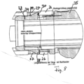
- the Figures 6 to 8 show an embodiment of the locking mechanism of the inner sleeve 23 according to the invention, which is composed of the front needle guard 24 and the rear spacer 25.
- the needle guard 24 contains two elongated tabs 26, in the end area of which two locking windows 27 are formed.
- Two locking hooks 28 are formed on the spacer 25 at corresponding positions, which snap into the locking windows 27 when the needle guard 24 is put together with the spacer 25.
- the end regions of the tabs 26 overlapping the spacers 25 fit flush into the recesses 29 of the spacers 25.
- the locking hooks 28 have a solid shape that is roughly wedge-shaped.
- the top side 29 of the locking hooks rises diagonally upwards in the direction of assembly, while the back side 30 of the locking hooks 28 is undercut at a flat angle. This makes the snap connection stable and practically inseparable.
- the two tabs 26 with the locking windows 27 have a different length, whereby the two corresponding areas of the locking windows are positioned accordingly so that only one mounting position is possible.
Landscapes
- Health & Medical Sciences (AREA)
- Life Sciences & Earth Sciences (AREA)
- Engineering & Computer Science (AREA)
- Animal Behavior & Ethology (AREA)
- Veterinary Medicine (AREA)
- Heart & Thoracic Surgery (AREA)
- Biomedical Technology (AREA)
- General Health & Medical Sciences (AREA)
- Public Health (AREA)
- Surgery (AREA)
- Medical Informatics (AREA)
- Anesthesiology (AREA)
- Hematology (AREA)
- Pathology (AREA)
- Nuclear Medicine, Radiotherapy & Molecular Imaging (AREA)
- Molecular Biology (AREA)
- Vascular Medicine (AREA)
- Dermatology (AREA)
- Infusion, Injection, And Reservoir Apparatuses (AREA)
Abstract
Description
- Die Erfindung betrifft eine Implantatspritze, die dazu verwendet wird, ein strangförmiges Feststoffimplantat mit einem Langzeitwirkstoff in den Körper eines Patienten abzugeben. Meist wird das Langzeitpräparat in die Bauchdecke eines Patienten gelegt, in die zuvor mittels einer Kanüle ein Aufnahmekanal für das Feststoffimplantat eingestochen wurde.
- Die Erfindung geht von einer Implantatspritze aus, die folgendes Merkmale enthält: Eine Kanüle, ein Depot-Element zur Aufnahme eines Feststoffimplantats, eine Außenhülse mit einem radial überstehenden vorderen Griffabschnitt, mit dem die Kanüle gemeinsam mit dem Depot-Element und der Außenhülse axial bewegbar ist, ferner eine Innenhülse, auf der die Außenhülse sitzt und in der die Kanüle mit dem Depot-Element verschiebbar ist, wobei die Innenhülse axiale Schlitze aufweist, die radiale Stege der Außenhülse durchgreifen, wobei die Implantatspritze ferner einen stabförmigen Kolben aufweist, der an einem rückwärtigen Griffabschnitt befestigt ist und teilweise von einer hinteren Hülse umgeben ist, die verschieblich in die Innenhülse eingreifen kann, wobei der stabförmige Kolben durch das Depot-Element in die Kanüle soweit vorschiebbar ist, dass zwischen der Spitze der Kanüle und dem Kopfende des Kolbens ein Abstand verbleibt, der etwa gleich der Länge des abzugebenden Feststoffimplantats ist, wobei die Außenhülse in der vorgeschobenen Ausgangsstellung bei freiliegender Kanüle durch eine Blockiereinrichtung der Innenhülse lösbar arretiert ist und die Blockiereinrichtung beim Vorschub der hinteren Hülse in ihre Endstellung in die Freigabestellung bewegt wird, wodurch die Außenhülse mittels des vorderen Griffabschnitts auf der Innenhülse soweit zurückziehbar ist, dass die Kanüle vollständig in die Innenhülse eintritt.
- Eine derartige Implantatspritze ist in der
DE 10 2017 007 893 A1 offenbart. Bei dieser Implantatspritze ist die Außenhülse durch radiale Stege einstückig mit einer Nadelhalterung verbunden, in deren Rückseite das Depot-Element, das das Feststoffimplantat aufnimmt, eingefügt wird. Nach der Montage von Innenhülse und Außenhülse wird in eine vordere Öffnung der Nadelhalterung die Kanüle eingeklebt. Das Feststoffimplantat wird durch die offene Rückseite der Innenhülse in das Depot-Element eingesetzt und durch den stabförmigen Kolben in dem Depot-Element in die leicht eingeklemmte Ausgangsposition vorgeschoben. Bei der Anwendung der Implantatspritze zur Abgabe des Feststoffimplantats an einen Patienten wird dann der hintere Griffabschnitt mit dem Kolben vorgeschoben, bis das Feststoffimplantat bis zur Spitze der Kanüle vorgeschoben ist, woraufhin die in dieser Position freigegebene Außenhülse mit der Kanüle und dem Depot-Element unter Zurücklassung des Feststoffimplantats im Körper des Patienten zurückgezogen wird. - Aus der
DE 10 2020 122 654 A1 ist eine Implantatspritze bekannt, bei der die Kanüle mit dem Depot-Element zu einer separaten, d.h. von der übrigen Implantatspritze getrennten Kanüleneinheit fest verbunden ist, wodurch das Einsetzen eines Feststoffimplantats in das Depot-Element erheblich vereinfacht ist. Die Erfindung sieht ferner vor, dass die Stege der Außenhülse an ihren radial inneren Enden an einem ringförmigen Aufnahmeteil angesetzt sind, das sich innerhalb der Innenhülse befindet, und dass die Kanüleneinheit mit in das Depot-Element eingesetztem Feststoff-implantat in das Aufnahmeteil einsteckbar und darin arretierbar ist. - Bei diesen bekannten Implantatspritzen ist die Innenhülse aus zwei Bauteilen zusammengesetzt, nämlich dem vorderen Nadelschutz und dem hinteren Abstandhalter, die miteinander verrastet sind. Hierzu sind zwei Rasthaken an langen Stegen des Nadelschutzes angeformt, die in Rastfenster des Abstandhalters einschnappen.
- Wenn auf diese Rastverbindung Zugkräfte einwirken, werden die Rasthaken gedehnt, wobei bauteilbedingt nur sehr wenig Platz für die Rasthaken verfügbar ist. Bei einem konstruktionsbedingten Querschnitt von vorzugsweise nur ca. 1,5 mm2 halten die Rasthaken nur einer Zugkraft von ca. 10 N stand. Wünschenswert ist aber eine höhere Haltekraft der Schnappverbindung und damit eine stabilere Ausbildung der Implantatspritze. Da bauteilbedingt nicht mehr Platz für Rasthaken mit größerem Querschnitt zur Verfügung steht, kommt eine Lösung des Problems durch Rasthaken mit größerem Querschnitt nicht in Betracht, ohne die Handhabbarkeit und das optische Erscheinungsbild der Implantatspritze zu verschlechtern.
- Der vorliegenden Erfindung liegt daher die Aufgabe zugrunde, eine bessere Rastverbindung anzugeben, bei der die Haltekraft erheblich erhöht ist.
- Diese Aufgabe erfindungsgemäß durch die Merkmale des Patentanspruchs 1 gelöst.
- Vorteilhafte Ausgestaltungen der Erfindung sind in den Unteransprüchen gekennzeichnet.
- Die Erfindung sieht vor, dass in zwei diametral gegenüber liegenden Laschen des Nadelschutzteils je ein Rastfenster ausgebildet ist, und dass der Abstandhalter an entsprechenden Positionen zwei Rasthaken aufweisen. Beim Verschnappen der beiden Bauteile gleiten die Laschen über die Rasthaken des Abstandhalters, bis die Rasthaken in die Rastfenster der Laschen einrasten. Dabei werden die Endabschnitte der beiden Laschen des Nadelschutzes bündig in Vertiefungen des Abstandhalters aufgenommen. Dabei entsteht eine stabile, unlösbare beidseitige Schnappverbindung, bei der beim Versuch, die beiden Bauteile durch Auseinander-ziehen zu trennen, die eingebrachte Kraft nicht mehr durch Dehnung des Kunststoffs, sondern durch Druck auf den Kunststoff aufgenommen wird. Hierdurch wird die Haltekraft der Verbindung signifikant erhöht, ohne dass der Außenumfang der Innenhülse vergrößert und sein optisches Erscheinungsbild signifikant verändert ist.
- In einer vorteilhaften Ausgestaltung der Erfindung haben die beiden Laschen des Nadelhalters, die die Rastfenster aufweisen, eine unterschiedliche Länge, so dass bei entsprechender Ausbildung der beiden Rasthakenbereiche nur eine einzige Montageposition der beiden Bauteile möglich ist.
- Die Rasthaken haben bevorzugt eine massive Keilform mit einer in Montagerichtung schräg ansteigender Oberseite und bevorzugt einer im flachen Winkel hinterschnittenen Rückseite, so dass die Schnappverbindung praktisch unlösbar ist. Dabei sollten die Endabschnitte der Laschen bündig in Einsenkungen des Abstandhalters eingreifen.
- Weitere Einzelheiten ergeben sich aus der nachfolgenden Beschreibung einer bevorzugten Ausführungsform der Implantatspritze sowie anhand der Zeichnungen. Dabei zeigen:
- Figuren 1a und 1b
- verschiedene Darstellungen einer Ausführungsform der Implantatspritze;
- Figuren 2a und 2b
- verschiedene Darstellungen der hinteren Hülse mit dem stabförmigen Kolben;
- Figur 3
- eine Ansicht der aus Nadelschutzteil und Abstandhalterteil zusammen gesetzten Innenhülse;
- Figur 4
- ein herkömmliches Nadelschutzteil der Innenhülse;
- Figur 5
- ein Abstandhalterteil der Innenhülse;
- Figur 6
- eine erfindungsgemäße Ausführungsform der Innenhülse;
- Figuren 7a und 7b
- den Nadelschutz und den Abstandhalter im getrennten Zustand;
- Figur 8
- eine Schnittdarstellung des verrasteten Zustands der Innenhülse.
- Die
Figuren 1a und1b zeigen einen Ausgangszustand der Implantatspritze, bei dem die Spritzennadel 1 von einer abnehmbaren Schutzkappe 2 überdeckt ist. Die abnehmbare Schutzkappe 2 ist mit einer Außenhülse 3 leicht lösbar verrastet. Die Außenhülse 3 hat eine lang gestreckte zylindrische Form, wobei an ihrem in den Figuren rechten Endabschnitt ein radial überstehender vorderer Griffabschnitt 4 angeformt ist. Die Außenhülse 3 ist über mehrere radial nach Innen verlaufende Stege 5 mit einer Nadelhalterung 6 fest verbunden, in der die Spritzennadel 1 befestigt ist. Axial hinter der Nadelhalterung 6 ist ein Präparataufnahmeteil 7 so angeordnet, dass sein Kanal 8 mit dem Kanal der Spritzennadel 1 fluchtet. In diesem Präparataufnahmeteil 8 befindet sich ein nicht dargestelltes Präparat, das beim Gebrauch der Implantatspritze z.B. in der Bauchdecke eines Patienten abgelegt wird. - Die Außenhülse 3 sitzt (wenn sie nicht blockiert ist) verschieblich auf einer Innenhülse 9, die aus einem vorderen Nadelschutz 10 und einem hinteren Abstandhalter 11 zusammengesetzt ist. Der Nadelschutz 10 enthält einen vorderen, sich kegelstumpfförmig verengenden Abschnitt 12, der in Umfangsrichtung geschlossen ist und die Spitze der vollständig zurück gezogenen Spritzennadel 1 überdeckt. Der axial anschließende Bereich enthält in Umfangsrichtung beabstandete Stege oder Laschen 13, wobei beim Stand der Technik an den Endabschnitten zweier Stege Haken 15 ausgebildet sind, die in Aussparungen 16 des Abstandhalters 11 der Innenhülse 9 einrasten, um die beiden Teile zu verbinden (
Figuren 4 und 5 ). - Der hintere Teil 11 der Innenhülse 9 enthält einen Federarm 17, der aus der Wand des Innenhülsenteils 11 freigeschnitten ist und mit einem Rasthaken radial nach außen vorsteht. Dieser Federarm 17 mit dem Rasthaken dient als Blockiereinrichtung für die Außenhülse 3, solange eine hintere Hülse 18 nicht in ihre Endstellung in den rückwärtigen Teil 11 der Innenhülse 9 eingeschoben ist.
- An dem rückwärtigen Ende der hinteren Hülse 18 ist ein flaches Griffstück 19 angeformt, an dem mittig in der Hülse 18 ein stabförmiger Kolben 20 befestigt ist. Die hintere Hülse 18 enthält einen in axialer Richtung verlaufenden Schlitz, der beim Einschieben der hinteren Hülse 18 in den rückwärtigen Abstandhalter 11 der Innenhülse 9 mittels einer schrägen Fläche so mit dem Federarm 17 zusammenwirkt, dass dessen Rasthaken radial nach innen gezogen wird. Dies ist der Fall, wenn die Innenseite des hinteren Griffstücks 19 an der rückwärtigen Randkante 22 der Innenhülse 9 anschlägt, wobei diese Position leicht lösbar verrastet wird.
- Nun kann die Außenhülse 3 zusammen mit der Spritzennadel 1 in ihrer Endposition zurückgezogen werden, in der die beiden Griffstücke 4 und 19 aneinander anliegen. Die Spitze der Spritzennadel 1 befindet sich nun innerhalb des kegelstumpfförmigen Abschnitts 12 der Innenhülse 9.
- Die
Figuren 6 bis 8 zeigen eine Ausführungsform der erfindungsgemäßen Verrastung der Innenhülse 23, die aus dem vorderen Nadelschutz 24 und dem hinteren Abstandhalter 25 zusammengesetzt ist. Der Nadelschutz 24 enthält zwei langgestreckte Laschen 26, in deren Endbereich zwei Rastfenster 27 ausgebildet sind. An dem Abstandhalter 25 sind an entsprechenden Positionen zwei Rasthaken 28 ausgebildet, die beim Zusammenstecken des Nadelschutzes 24 mit dem Abstandhalter 25 in die Rastfenster 27 einschnappen. Die sich mit dem Abstandhalter 25 überlappenden Endbereiche der Laschen 26 treten dabei bündig in Einsenkungen 29 der Abstandhalter 25 ein. - Die Rasthaken 28 haben eine massive Gestalt, die etwa keilförmig ist. Die Oberseite 29 der Rasthaken steigt in Montagerichtung schräg nach oben an, während die Rückseite 30 der Rasthaken 28 in einem flachen Winkel hinterschnitten ist. Hierdurch ist die Schnappverbindung stabil und praktisch unlösbar.
- Die beiden Laschen 26 mit den Rastfenstern 27 haben eine unterschiedliche Länge, wobei die beiden zugehörigen Bereiche der Rastfenster entsprechend positioniert sind, so dass nur eine Montageposition möglich ist.
Claims (4)
- Implantatspritze mit einer Kanüle, mit einem Depot-Element zur Aufnahme eines Feststoffimplantats, mit einer Außenhülse mit einem radial überstehenden vorderen Griffabschnitt, mit dem die Kanüle, das Depot-Element und die Außenhülse gemeinsam axial bewegbar sind,mit einer Innenhülse, auf der die Außenhülse sitzt und in der die Kanüle mit dem Depot-Element verschiebbar ist, wobei die Innenhülse axiale Schlitze aufweist, die radiale Stege der Außenhülse durchgreifen,ferner mit einem stabförmigen Kolben, der an einem rückwärtigen Griffabschnitt befestigt ist und teilweise von einer hinteren Hülse umgeben ist, die verschieblich in die Innenhülse eingreifen kann,wobei der stabförmige Kolben durch das Depot-Element in die Kanüle so weit vorschiebbar ist, dass zwischen der Spitze der Kanüle und dem Kopfende des Kolbens ein Abstand verbleibt, der etwa gleich der Länge des abzugebenden Feststoffimplantats ist,wobei die Außenhülse in der vorgeschobenen Ausgangsstellung bei freiliegender Kanüle durch eine Blockiereinrichtung der Innenhülse lösbar arretiert ist und die Blockiereinrichtung beim Vorschub der hinteren Hülse in ihre Endstellung in die Freigabestellung bewegt wird, wodurch die Außenhülse mittels des vorderen Griffabschnitts auf der Innenhülse zurückziehbar ist, so dass die Kanüle vollständig in die Innenhülse eintritt, und wobei die Innenhülse aus einem vorderen Nadelschutz und einem hinteren Abstandhalter zusammengesetzt ist, die miteinander verrastet sind,dadurch gekennzeichnet,dass in zwei gegenüberliegenden Laschen (26) des Nadelschutzes (24) je ein Rastfenster (27) ausgebildet ist,dass der Abstandshalter (25) an entsprechenden Positionen zwei Rasthaken (28) aufweisen unddass zum Verbinden der beiden Bauteile die Laschen (26) über die Rasthaken (28) des Abstandhalters (25) gleiten, bis die Rasthaken (28) in die Rastfenster (27) einrasten.
- Implantatspritze nach Anspruch 1,
dadurch gekennzeichnet,
dass bei der Schnappverbindung die Endabschnitte der Laschen (26) bündig in Einsenkungen (29) des Abstandhalters (25) eingreifen. - Implantatspritze nach einem der Ansprüche 1 oder 2,
dadurch gekennzeichnet,
dass die Rasthaken (28) im wesentlichen eine massive Keilform haben mit einer in Montagerichtung schräg ansteigenden Oberseite (29) und einer im flachen Winkel hinterschnittenen Rückseite (30), so dass die Schnappverbindung unlösbar ist. - Implantatspritze nach einem der Ansprüche 1 bis 3,
dadurch gekennzeichnet,
dass die beiden Laschen (26) eine unterschiedliche Länge haben und die beiden Bereiche der Rastfenster (27) entsprechend ausgebildet sind, so dass nur eine Montageposition möglich ist.
Applications Claiming Priority (1)
| Application Number | Priority Date | Filing Date | Title |
|---|---|---|---|
| DE102023117652.8A DE102023117652A1 (de) | 2023-07-04 | 2023-07-04 | Implantatspritze |
Publications (2)
| Publication Number | Publication Date |
|---|---|
| EP4487897A1 true EP4487897A1 (de) | 2025-01-08 |
| EP4487897B1 EP4487897B1 (de) | 2025-10-22 |
Family
ID=93843198
Family Applications (1)
| Application Number | Title | Priority Date | Filing Date |
|---|---|---|---|
| EP24169212.8A Active EP4487897B1 (de) | 2023-07-04 | 2024-04-09 | Implantatspritze |
Country Status (6)
| Country | Link |
|---|---|
| US (1) | US20250010051A1 (de) |
| EP (1) | EP4487897B1 (de) |
| CN (1) | CN119257698A (de) |
| AU (1) | AU2024203177A1 (de) |
| DE (1) | DE102023117652A1 (de) |
| MX (1) | MX2024008431A (de) |
Citations (3)
| Publication number | Priority date | Publication date | Assignee | Title |
|---|---|---|---|---|
| DE102017007893A1 (de) | 2017-08-19 | 2019-02-21 | Gaplast Gmbh | Implantatspritze |
| DE102020122654A1 (de) | 2020-08-31 | 2022-03-03 | Gaplast Gmbh | Implantatspritze |
| WO2023011913A1 (de) * | 2021-08-03 | 2023-02-09 | Amw Gmbh | Applikationsvorrichtung für mindestens ein implantat |
Family Cites Families (2)
| Publication number | Priority date | Publication date | Assignee | Title |
|---|---|---|---|---|
| WO2015074983A2 (en) * | 2013-11-22 | 2015-05-28 | Sanofi-Aventis Deutschland Gmbh | Drug delivery device with dose delivery clicker |
| CN210170597U (zh) * | 2019-05-21 | 2020-03-24 | 杭州吉姆士医疗科技有限公司 | 一种胰岛素笔帽 |
-
2023
- 2023-07-04 DE DE102023117652.8A patent/DE102023117652A1/de active Pending
- 2023-11-07 CN CN202311468054.6A patent/CN119257698A/zh active Pending
-
2024
- 2024-04-03 US US18/625,489 patent/US20250010051A1/en active Pending
- 2024-04-09 EP EP24169212.8A patent/EP4487897B1/de active Active
- 2024-05-14 AU AU2024203177A patent/AU2024203177A1/en active Pending
- 2024-07-03 MX MX2024008431A patent/MX2024008431A/es unknown
Patent Citations (3)
| Publication number | Priority date | Publication date | Assignee | Title |
|---|---|---|---|---|
| DE102017007893A1 (de) | 2017-08-19 | 2019-02-21 | Gaplast Gmbh | Implantatspritze |
| DE102020122654A1 (de) | 2020-08-31 | 2022-03-03 | Gaplast Gmbh | Implantatspritze |
| WO2023011913A1 (de) * | 2021-08-03 | 2023-02-09 | Amw Gmbh | Applikationsvorrichtung für mindestens ein implantat |
Also Published As
| Publication number | Publication date |
|---|---|
| AU2024203177A1 (en) | 2025-01-23 |
| EP4487897B1 (de) | 2025-10-22 |
| MX2024008431A (es) | 2025-02-10 |
| DE102023117652A1 (de) | 2025-01-09 |
| US20250010051A1 (en) | 2025-01-09 |
| CN119257698A (zh) | 2025-01-07 |
Similar Documents
| Publication | Publication Date | Title |
|---|---|---|
| DE68908975T2 (de) | Mit einer Nadelhülse verbundene Spritze und Verfahren zur Herstellung. | |
| EP0412968B1 (de) | Spritze, insbesondere für den medizinischen gebrauch | |
| DE60000038T2 (de) | Injektionsvorrichtung für Einmalverwendung | |
| EP3421067B1 (de) | Injektionsvorrichtung, insbesondere autoinjektor mit stechschutz oder/und überlastsicherung für ein produktbehältnis | |
| EP2094342B1 (de) | Kathetervorrichtung mit infusionsport und ventilen | |
| DE69822160T2 (de) | Verbesserte injektionsspritze | |
| DE69607409T2 (de) | Venenkatheter mit automatischem Kanülenspitzenschutz | |
| EP2678054B1 (de) | Injektionsspritzenkopf, auspresseinheit sowie daraus gebildete injektionsspritze | |
| EP3456374B1 (de) | Implantatspritze | |
| DE69813050T2 (de) | Spritzvorrichtung mit Schutzhülle | |
| EP2085147B1 (de) | Vorrichtung mit Druck beaufschlagtem Kolben zum Austragen einer Mehrfachspritze oder Mehrfachkartusche | |
| DE202011109359U1 (de) | Automatische Injektionsspritze | |
| DE10207276A1 (de) | Nadel-Insertionsvorrichtung mit quer bewegbarem Halteelement | |
| DE20104539U1 (de) | Intravenöse Kathetervorrichtung | |
| EP0420126A1 (de) | Blutentnahmevorrichtung | |
| WO1999007434A1 (de) | Implantatspritze | |
| EP3960223B1 (de) | Implantatspritze | |
| DE9310370U1 (de) | Intravenöse Nadel | |
| DE29912965U1 (de) | Injektionsvorrichtung | |
| WO2013167431A1 (de) | Kanüle mit verschiebbar angeordnetem mandrin | |
| EP1709990B1 (de) | Vorrichtung zum Fixieren einer Elektrode im Schrittmacherbett | |
| DE4414381A1 (de) | Vorrichtung zum Verbinden einer Verkleidung mit einer Unterverkleidung | |
| DE60032171T2 (de) | Verbesserungen bezüglich subkutaninjektionsspritzen | |
| EP2078535A1 (de) | Implantatspritze | |
| EP2173411A1 (de) | Vorrichtung zum applizieren einer kanüle |
Legal Events
| Date | Code | Title | Description |
|---|---|---|---|
| PUAI | Public reference made under article 153(3) epc to a published international application that has entered the european phase |
Free format text: ORIGINAL CODE: 0009012 |
|
| STAA | Information on the status of an ep patent application or granted ep patent |
Free format text: STATUS: THE APPLICATION HAS BEEN PUBLISHED |
|
| AK | Designated contracting states |
Kind code of ref document: A1 Designated state(s): AL AT BE BG CH CY CZ DE DK EE ES FI FR GB GR HR HU IE IS IT LI LT LU LV MC ME MK MT NL NO PL PT RO RS SE SI SK SM TR |
|
| STAA | Information on the status of an ep patent application or granted ep patent |
Free format text: STATUS: REQUEST FOR EXAMINATION WAS MADE |
|
| 17P | Request for examination filed |
Effective date: 20250228 |
|
| P01 | Opt-out of the competence of the unified patent court (upc) registered |
Free format text: CASE NUMBER: APP_29748/2025 Effective date: 20250623 |
|
| GRAP | Despatch of communication of intention to grant a patent |
Free format text: ORIGINAL CODE: EPIDOSNIGR1 |
|
| STAA | Information on the status of an ep patent application or granted ep patent |
Free format text: STATUS: GRANT OF PATENT IS INTENDED |
|
| RIC1 | Information provided on ipc code assigned before grant |
Ipc: A61M 37/00 20060101AFI20250707BHEP Ipc: A61M 25/06 20060101ALN20250707BHEP |
|
| INTG | Intention to grant announced |
Effective date: 20250804 |
|
| GRAS | Grant fee paid |
Free format text: ORIGINAL CODE: EPIDOSNIGR3 |
|
| GRAA | (expected) grant |
Free format text: ORIGINAL CODE: 0009210 |
|
| STAA | Information on the status of an ep patent application or granted ep patent |
Free format text: STATUS: THE PATENT HAS BEEN GRANTED |
|
| AK | Designated contracting states |
Kind code of ref document: B1 Designated state(s): AL AT BE BG CH CY CZ DE DK EE ES FI FR GB GR HR HU IE IS IT LI LT LU LV MC ME MK MT NL NO PL PT RO RS SE SI SK SM TR |
|
| REG | Reference to a national code |
Ref country code: CH Ref legal event code: F10 Free format text: ST27 STATUS EVENT CODE: U-0-0-F10-F00 (AS PROVIDED BY THE NATIONAL OFFICE) Effective date: 20251022 Ref country code: GB Ref legal event code: FG4D Free format text: NOT ENGLISH |
|
| REG | Reference to a national code |
Ref country code: DE Ref legal event code: R096 Ref document number: 502024000316 Country of ref document: DE |
|
| REG | Reference to a national code |
Ref country code: IE Ref legal event code: FG4D Free format text: LANGUAGE OF EP DOCUMENT: GERMAN |
|
| REG | Reference to a national code |
Ref country code: CH Ref legal event code: R17 Free format text: ST27 STATUS EVENT CODE: U-0-0-R10-R17 (AS PROVIDED BY THE NATIONAL OFFICE) Effective date: 20251201 |
|
| REG | Reference to a national code |
Ref country code: NL Ref legal event code: MP Effective date: 20251022 |
|
| PG25 | Lapsed in a contracting state [announced via postgrant information from national office to epo] |
Ref country code: NL Free format text: LAPSE BECAUSE OF FAILURE TO SUBMIT A TRANSLATION OF THE DESCRIPTION OR TO PAY THE FEE WITHIN THE PRESCRIBED TIME-LIMIT Effective date: 20251022 |
|
| PG25 | Lapsed in a contracting state [announced via postgrant information from national office to epo] |
Ref country code: ES Free format text: LAPSE BECAUSE OF FAILURE TO SUBMIT A TRANSLATION OF THE DESCRIPTION OR TO PAY THE FEE WITHIN THE PRESCRIBED TIME-LIMIT Effective date: 20251022 |
|
| REG | Reference to a national code |
Ref country code: LT Ref legal event code: MG9D |
|
| PG25 | Lapsed in a contracting state [announced via postgrant information from national office to epo] |
Ref country code: NO Free format text: LAPSE BECAUSE OF FAILURE TO SUBMIT A TRANSLATION OF THE DESCRIPTION OR TO PAY THE FEE WITHIN THE PRESCRIBED TIME-LIMIT Effective date: 20260122 |
|
| PG25 | Lapsed in a contracting state [announced via postgrant information from national office to epo] |
Ref country code: HR Free format text: LAPSE BECAUSE OF FAILURE TO SUBMIT A TRANSLATION OF THE DESCRIPTION OR TO PAY THE FEE WITHIN THE PRESCRIBED TIME-LIMIT Effective date: 20251022 Ref country code: FI Free format text: LAPSE BECAUSE OF FAILURE TO SUBMIT A TRANSLATION OF THE DESCRIPTION OR TO PAY THE FEE WITHIN THE PRESCRIBED TIME-LIMIT Effective date: 20251022 |
|
| PG25 | Lapsed in a contracting state [announced via postgrant information from national office to epo] |
Ref country code: RS Free format text: LAPSE BECAUSE OF FAILURE TO SUBMIT A TRANSLATION OF THE DESCRIPTION OR TO PAY THE FEE WITHIN THE PRESCRIBED TIME-LIMIT Effective date: 20260122 |
|
| PG25 | Lapsed in a contracting state [announced via postgrant information from national office to epo] |
Ref country code: IS Free format text: LAPSE BECAUSE OF FAILURE TO SUBMIT A TRANSLATION OF THE DESCRIPTION OR TO PAY THE FEE WITHIN THE PRESCRIBED TIME-LIMIT Effective date: 20260222 |
|
| PGFP | Annual fee paid to national office [announced via postgrant information from national office to epo] |
Ref country code: TR Payment date: 20260309 Year of fee payment: 3 |
|
| PG25 | Lapsed in a contracting state [announced via postgrant information from national office to epo] |
Ref country code: PT Free format text: LAPSE BECAUSE OF FAILURE TO SUBMIT A TRANSLATION OF THE DESCRIPTION OR TO PAY THE FEE WITHIN THE PRESCRIBED TIME-LIMIT Effective date: 20260223 |
|
| PG25 | Lapsed in a contracting state [announced via postgrant information from national office to epo] |
Ref country code: PL Free format text: LAPSE BECAUSE OF FAILURE TO SUBMIT A TRANSLATION OF THE DESCRIPTION OR TO PAY THE FEE WITHIN THE PRESCRIBED TIME-LIMIT Effective date: 20251022 |
|
| PG25 | Lapsed in a contracting state [announced via postgrant information from national office to epo] |
Ref country code: LV Free format text: LAPSE BECAUSE OF FAILURE TO SUBMIT A TRANSLATION OF THE DESCRIPTION OR TO PAY THE FEE WITHIN THE PRESCRIBED TIME-LIMIT Effective date: 20251022 |
|
| PG25 | Lapsed in a contracting state [announced via postgrant information from national office to epo] |
Ref country code: BG Free format text: LAPSE BECAUSE OF FAILURE TO SUBMIT A TRANSLATION OF THE DESCRIPTION OR TO PAY THE FEE WITHIN THE PRESCRIBED TIME-LIMIT Effective date: 20251022 |