EP4485641A1 - Energiespeichervorrichtung und elektrizitätsverbrauchsvorrichtung - Google Patents
Energiespeichervorrichtung und elektrizitätsverbrauchsvorrichtung Download PDFInfo
- Publication number
- EP4485641A1 EP4485641A1 EP24169428.0A EP24169428A EP4485641A1 EP 4485641 A1 EP4485641 A1 EP 4485641A1 EP 24169428 A EP24169428 A EP 24169428A EP 4485641 A1 EP4485641 A1 EP 4485641A1
- Authority
- EP
- European Patent Office
- Prior art keywords
- electrolyte
- energy
- storage device
- electrode assembly
- inlet pipe
- Prior art date
- Legal status (The legal status is an assumption and is not a legal conclusion. Google has not performed a legal analysis and makes no representation as to the accuracy of the status listed.)
- Granted
Links
Images

Classifications
-
- H—ELECTRICITY
- H01—ELECTRIC ELEMENTS
- H01M—PROCESSES OR MEANS, e.g. BATTERIES, FOR THE DIRECT CONVERSION OF CHEMICAL ENERGY INTO ELECTRICAL ENERGY
- H01M50/00—Constructional details or processes of manufacture of the non-active parts of electrochemical cells other than fuel cells, e.g. hybrid cells
- H01M50/60—Arrangements or processes for filling or topping-up with liquids; Arrangements or processes for draining liquids from casings
- H01M50/609—Arrangements or processes for filling with liquid, e.g. electrolytes
- H01M50/627—Filling ports
-
- H—ELECTRICITY
- H01—ELECTRIC ELEMENTS
- H01M—PROCESSES OR MEANS, e.g. BATTERIES, FOR THE DIRECT CONVERSION OF CHEMICAL ENERGY INTO ELECTRICAL ENERGY
- H01M50/00—Constructional details or processes of manufacture of the non-active parts of electrochemical cells other than fuel cells, e.g. hybrid cells
- H01M50/60—Arrangements or processes for filling or topping-up with liquids; Arrangements or processes for draining liquids from casings
- H01M50/673—Containers for storing liquids; Delivery conduits therefor
- H01M50/682—Containers for storing liquids; Delivery conduits therefor accommodated in battery or cell casings
-
- H—ELECTRICITY
- H01—ELECTRIC ELEMENTS
- H01M—PROCESSES OR MEANS, e.g. BATTERIES, FOR THE DIRECT CONVERSION OF CHEMICAL ENERGY INTO ELECTRICAL ENERGY
- H01M50/00—Constructional details or processes of manufacture of the non-active parts of electrochemical cells other than fuel cells, e.g. hybrid cells
- H01M50/10—Primary casings; Jackets or wrappings
- H01M50/102—Primary casings; Jackets or wrappings characterised by their shape or physical structure
- H01M50/103—Primary casings; Jackets or wrappings characterised by their shape or physical structure prismatic or rectangular
-
- H—ELECTRICITY
- H01—ELECTRIC ELEMENTS
- H01M—PROCESSES OR MEANS, e.g. BATTERIES, FOR THE DIRECT CONVERSION OF CHEMICAL ENERGY INTO ELECTRICAL ENERGY
- H01M50/00—Constructional details or processes of manufacture of the non-active parts of electrochemical cells other than fuel cells, e.g. hybrid cells
- H01M50/10—Primary casings; Jackets or wrappings
- H01M50/147—Lids or covers
- H01M50/148—Lids or covers characterised by their shape
- H01M50/15—Lids or covers characterised by their shape for prismatic or rectangular cells
-
- H—ELECTRICITY
- H01—ELECTRIC ELEMENTS
- H01M—PROCESSES OR MEANS, e.g. BATTERIES, FOR THE DIRECT CONVERSION OF CHEMICAL ENERGY INTO ELECTRICAL ENERGY
- H01M50/00—Constructional details or processes of manufacture of the non-active parts of electrochemical cells other than fuel cells, e.g. hybrid cells
- H01M50/50—Current conducting connections for cells or batteries
- H01M50/572—Means for preventing undesired use or discharge
- H01M50/584—Means for preventing undesired use or discharge for preventing incorrect connections inside or outside the batteries
- H01M50/586—Means for preventing undesired use or discharge for preventing incorrect connections inside or outside the batteries inside the batteries, e.g. incorrect connections of electrodes
-
- H—ELECTRICITY
- H01—ELECTRIC ELEMENTS
- H01M—PROCESSES OR MEANS, e.g. BATTERIES, FOR THE DIRECT CONVERSION OF CHEMICAL ENERGY INTO ELECTRICAL ENERGY
- H01M50/00—Constructional details or processes of manufacture of the non-active parts of electrochemical cells other than fuel cells, e.g. hybrid cells
- H01M50/50—Current conducting connections for cells or batteries
- H01M50/572—Means for preventing undesired use or discharge
- H01M50/584—Means for preventing undesired use or discharge for preventing incorrect connections inside or outside the batteries
- H01M50/59—Means for preventing undesired use or discharge for preventing incorrect connections inside or outside the batteries characterised by the protection means
-
- H—ELECTRICITY
- H01—ELECTRIC ELEMENTS
- H01M—PROCESSES OR MEANS, e.g. BATTERIES, FOR THE DIRECT CONVERSION OF CHEMICAL ENERGY INTO ELECTRICAL ENERGY
- H01M50/00—Constructional details or processes of manufacture of the non-active parts of electrochemical cells other than fuel cells, e.g. hybrid cells
- H01M50/70—Arrangements for stirring or circulating the electrolyte
- H01M50/73—Electrolyte stirring by the action of gas on or in the electrolyte
-
- H—ELECTRICITY
- H01—ELECTRIC ELEMENTS
- H01M—PROCESSES OR MEANS, e.g. BATTERIES, FOR THE DIRECT CONVERSION OF CHEMICAL ENERGY INTO ELECTRICAL ENERGY
- H01M2220/00—Batteries for particular applications
- H01M2220/10—Batteries in stationary systems, e.g. emergency power source in plant
-
- Y—GENERAL TAGGING OF NEW TECHNOLOGICAL DEVELOPMENTS; GENERAL TAGGING OF CROSS-SECTIONAL TECHNOLOGIES SPANNING OVER SEVERAL SECTIONS OF THE IPC; TECHNICAL SUBJECTS COVERED BY FORMER USPC CROSS-REFERENCE ART COLLECTIONS [XRACs] AND DIGESTS
- Y02—TECHNOLOGIES OR APPLICATIONS FOR MITIGATION OR ADAPTATION AGAINST CLIMATE CHANGE
- Y02E—REDUCTION OF GREENHOUSE GAS [GHG] EMISSIONS, RELATED TO ENERGY GENERATION, TRANSMISSION OR DISTRIBUTION
- Y02E60/00—Enabling technologies; Technologies with a potential or indirect contribution to GHG emissions mitigation
- Y02E60/10—Energy storage using batteries
Definitions
- the disclosure relates to the field of energy-storage technologies, and in particular, to an energy-storage device and an electricity-consumption apparatus.
- electrode assemblies are typically immersed in electrolytes to ensure the normal operation of the energy-storage devices.
- the consumption of the electrolyte during charging and discharging will lower the electrolyte level, which may cause that part of the electrode assembly in the energy-storage device cannot be immersed in the electrolyte, affecting the performance of the electrode assembly and thereby shortening the service life of the energy-storage device.
- the disclosure provides an energy-storage device.
- the energy-storage device includes an electrode assembly and a housing assembly.
- the housing assembly includes a housing and an electrolyte pipeline.
- the electrolyte pipeline and the electrode assembly are both mounted inside the housing.
- the electrolyte pipeline is located between the electrode assembly and the housing and includes an electrolyte inlet pipe and an electrolyte outlet pipe.
- the electrolyte inlet pipe is located at one side of the electrode assembly and in communication with an interior of the housing.
- the electrolyte outlet pipe is fixedly mounted to and in communication with the electrolyte inlet pipe.
- the electrolyte outlet pipe defines multiple electrolyte outlet holes that are arranged at intervals in sequence.
- Each of the multiple electrolyte outlet holes extends, in a thickness direction of the electrolyte outlet pipe, through a pipe wall of the electrolyte outlet pipe at one side of the electrolyte outlet pipe.
- Each of the multiple electrolyte outlet holes has an opening facing the electrode assembly of the energy-storage device.
- green energy mainly includes solar energy, wind energy, water potential, and the like.
- solar energy, wind energy, and the other forms of energy generally suffer from strong intermittency and large fluctuations, which can cause instability of the green power grid (insufficient electricity during peak electricity consumption, excess electricity during off-peak periods). Unstable voltages can also damage power systems. Therefore, insufficient electricity demand or insufficient power grid capacity may lead to the problem of "curtailment of wind and solar power”.
- the current application scenarios of energy storage are relatively extensive, including power-generating-side energy storage, grid-side energy storage, renewable energy grid integration energy storage, and user-side energy storage.
- the corresponding types of energy-storage devices include:
- the disclosure provides an energy-storage device and an electricity-consumption apparatus, which can ensure that electrode assemblies of the energy-storage device are all immersed in an electrolyte, thereby preventing the performance of the electrode assemblies from being affected, and prolonging the service life of the energy-storage device.
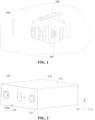
- FIG. 1 is a diagram of an application scenario of an energy-storage system according to an embodiment of the disclosure.
- FIG. 1 illustrates a household energy-storage system.
- the household energy-storage system includes an energy-storage device 100, an electrical energy conversion apparatus 200 (such as a photovoltaic panel), and a user load 300 (such as a street lamp, a household appliance, etc.).
- the energy-storage device 100 may be a small-size energy-storage box, and can be installed on an outdoor wall through wall mounting.
- the electrical energy conversion apparatus 200 may convert solar energy into electrical energy during off-peak electricity price periods, and store the electrical energy into the energy-storage device 100.
- the electrical energy stored in the energy-storage device 100 can then be configured to power the user load 300 during peak electricity price periods, or during grid power outages, blackouts, or loss of electricity.
- electrochemical energy-storage is taken as an example, and the energy-storage device 100 includes at least one group of chemical batteries.
- Chemical elements in the chemical batteries are used as an energy-storage medium, so that a charging and discharging process can be achieved through a chemical reaction or change of the energy-storage medium.
- the electrical energy generated by the optical energy and wind energy can be stored in at least one group of chemical batteries through a chemical reaction or change of an energy-storage medium, and when the usage of the external electrical energy peaks, the electrical energy stored in the at least one group of chemical batteries can be released for use through the chemical reaction or change of the energy-storage medium, or transferred to areas with insufficient electricity for use.
- the embodiments of the disclosure provide the energy-storage device 100.
- the energy-storage device 100 may be, but is not limited to, a battery cell (such as a secondary battery) and a device such as a battery module, a battery pack, a battery system, and the like formed by battery cells.
- the battery cell may be a lithium-ion battery, a lithium-sulfur battery, a sodium lithium-ion battery, a sodium-ion battery, a magnesium-ion battery, etc.
- the battery cell may be cylindrical, flat, rectangular, etc., and the embodiments of the disclosure are not limited thereto.
- the following describes the energy-storage device 100 in detail by taking an example in which the energy-storage device 100 is a prismatic battery cell.
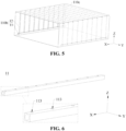
- FIG. 2 is a schematic structural diagram of the energy-storage device 100 of the energy-storage system in FIG. 1
- FIG. 3 is a schematic exploded structural view of the energy-storage device 100 in FIG. 2
- a length direction of the energy-storage device 100 is defined as the X-axis direction
- a width direction of the energy-storage device 100 is defined as the Y-axis direction
- a thickness direction of the energy-storage device 100 is defined as the Z-axis direction.
- the X-axis direction, the Y-axis direction, and the Z-axis direction are perpendicular to one another.
- the energy-storage device 100 includes a housing assembly 110, an electrode assembly 120, and an end cover assembly 130.
- the electrode assembly 120 and the end cover assembly 130 are both mounted to the housing assembly 110.
- the housing assembly 110 includes a housing 110a, an electrolyte pipeline 110b, and an insulation film 110c. Both the electrolyte pipeline 110b and the insulation film 110c are mounted inside the housing 110a.
- the housing 110a includes a placement surface 114 and an appearance surface 115.
- the appearance surface 115 is opposite to the placement surface 114 in the thickness direction of the energy-storage device 100 (i.e., the Z-axis direction illustrated).
- the housing 110a further defines an opening 111 and an accommodating cavity 112.
- the accommodating cavity 112 is in communication with the opening 111. Specifically, both the electrolyte pipeline 110b and the insulation film 110c are received in the accommodating cavity 112.
- the accommodating cavity 112 is also configured for receiving an electrolyte.
- the electrode assembly 120 is accommodated in the accommodating cavity 112. At least part of the electrode assembly 120 is immersed in the electrolyte. It may be understood that, the electrode assembly 120 has a separator (not illustrated). The separator can absorb the electrolyte through capillary action, so that the electrolyte can impregnate the electrode assembly 120.
- the electrode assembly 120 is a wound electrode assembly. Specifically, the electrode assembly 120 is mounted inside the electrolyte pipeline 110b and the insulation film 110c. In other words, the electrolyte pipeline 110b and the insulation film 110c are positioned between the electrode assembly 120 and the housing 110a.
- the two electrode assemblies 120 include a first electrode assembly 120a and a second electrode assembly 120b.
- the first electrode assembly 120a is electrically connected to the second electrode assembly 120b.
- the first electrode assembly 120a is arranged on the top side of the second electrode assembly 120b. In some other embodiments, there may be one electrode assembly 120, which is not limited herein.
- the end cover assembly 130 is mounted on one side, in the length direction (i.e., the Y-axis direction illustrated), of the housing 110a.
- the end cover assembly 130 seals the opening 111.
- the end cover assembly 130 is electrically connected to the electrode assembly 120.
- the end cover assembly 130 is provided with a placement indicator 130a.
- the placement indicator 130a is on one side of the end cover assembly 130 close to the placement surface 114.
- the placement indicator 130a can be configured to indicate the placement surface 114 of the energy-storage device 100. When the energy-storage device 100 is placed flat, it can ensure that an electrolyte inlet pipe 11 of the electrolyte pipeline 110b is immersed in the electrolyte.
- top and bottom used in the disclosure are described with reference to the orientations illustrated in FIG. 1 .
- a direction towards the positive Z-axis position is referred to as "top”
- a direction towards the negative Z-axis direction is referred to as "bottom”.
- the terms are not intended to indicate or imply that the device or component referred to must have a specific orientation, or be constructed and operated in a specific orientation, and therefore cannot be construed as limitations to the disclosure.
- FIG. 4 is a schematic structural view of an assembly of the electrolyte pipeline 110b and the insulation film 110c of the housing assembly 110 of the energy-storage device 100 in FIG. 2
- FIG. 5 is a perspective view of the assembly of the electrolyte pipeline 110b and the insulation film 110c of the housing assembly 110 in FIG. 4
- FIG. 6 is a schematic structural view of the electrolyte inlet pipe 11 of the electrolyte pipeline 110b in FIG. 4 .
- the insulation film 110c is disposed inside the housing 110a.
- the insulation film 110c defines an opening (not illustrated) on one side of the insulation film 110c facing the end cover assembly 130.
- the electrode assembly 120 and the electrolyte pipeline 110b are both disposed inside the insulation film 110c.
- the electrolyte pipeline 110b is located between the electrode assembly 120 and the insulation film 110c.
- the insulation film 110c is a Mylar film.
- the insulation film 110c and the electrolyte pipeline 110b may be fixed through ultrasonic heat fusion.
- the insulation film 110c may not only prevent direct contact between the electrode assembly 120 and the housing 110a, thus avoiding short circuit of the electrode assembly 120, but also prevent the electrolyte pipeline 110b and the electrode assembly 120 from being scratched during installation to the housing 110a.
- the electrolyte pipeline 110b is configured to absorb the electrolyte and make the electrolyte to flow back to a surface of the electrode assembly 120 to impregnate the electrode assembly 120.
- the electrolyte pipeline 110b includes the electrolyte inlet pipe 11 and an electrolyte outlet pipe 12.
- the electrolyte outlet pipe 12 is fixedly mounted to the electrolyte inlet pipe 11.
- the electrolyte inlet pipe 11 is in an interference fit with the electrolyte outlet pipe 12, thereby ensuring stability of assembly between the electrolyte inlet pipe 11 and the electrolyte outlet pipe 12.
- the electrolyte inlet pipe 11 and the electrolyte outlet pipe 12 may also be fixedly mounted in an adhesive manner.
- the electrolyte pipeline 110b is provided.
- the difference between the internal pressure and the external pressure of the electrolyte inlet pipe 11 of the electrolyte pipeline110b is utilized, so that the electrolyte can flow from the electrolyte inlet pipe 11 into the electrolyte outlet pipe 12 and flow out through multiple electrolyte outlet holes 123 of the electrolyte outlet pipe 12.
- This enables the electrolyte to be dripped onto a surface of the electrode assembly 120, so that the electrode assembly 120 can be immersed in the electrolyte, thereby ensuring that the electrode assembly 120 remains fully immersed in the electrolyte. Therefore, the performance of the electrode assembly 120 can be prevented from being affected, and the service life of the energy-storage device 100 can be prolonged.
- the electrolyte inlet pipe 11 is located at one side of the electrode assembly 120, and the electrolyte inlet pipe 11 is in communication with the interior of the housing 110a. At least part of the electrolyte inlet pipe 11 is immersed in the electrolyte to ensure that the electrolyte can smoothly enter the electrolyte inlet pipe 11 and flow into the entire electrolyte pipeline 110b, thereby impregnating the electrode assembly 120.
- an external pressure of the electrolyte inlet pipe 11 is greater than an internal pressure of the electrolyte inlet pipe 11.
- a difference between the external pressure of the electrolyte inlet pipe 11 and the internal pressure of the electrolyte inlet pipe 11 ranges from 0.2 MPa to 0.3 MPa.
- the electrolyte inlet pipe 11 is implemented as two electrolyte inlet pipes 11.
- the two electrolyte inlet pipes 11 are spaced apart from each other.
- One of the two electrolyte inlet pipes 11 is located at one of two opposite sides of the electrode assembly 120, and the other of the two electrolyte inlet pipes 11 is located at the other of two opposite sides of the electrode assembly 120.
- the two electrolyte inlet pipes 11 are both in communication with the interior of the housing 110a.
- the electrolyte in the housing 110a can flow into the electrolyte pipeline 110b through the electrolyte inlet pipe 11.
- the two electrolyte inlet pipes 11 are both circular pipelines.
- a ratio of a height of the electrolyte inlet pipe 11 to a height of the electrode assembly 120 ranges from 1/6 to 1/3.
- a diameter of the electrolyte inlet pipe 11 ranges from 5 mm to 10 mm, facilitating subsequent processing of the electrolyte inlet pipe 11.
- Each electrolyte inlet pipe 11 defines multiple mounting holes 113.
- the multiple mounting holes 113 are arranged at intervals in a length direction of the electrolyte inlet pipe 11.
- Each mounting hole 113 extends, in a thickness direction of the electrolyte inlet pipe 11, through a pipe wall of the electrolyte inlet pipe at one side of the electrolyte inlet pipe 11.
- the multiple mounting holes 113 are circular holes. In some other embodiments, the multiple mounting holes 113 may also be square holes or other irregular holes.
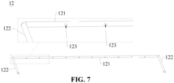
- FIG. 7 is a schematic structural view of the electrolyte outlet pipe 12 of the electrolyte pipeline 110b in FIG. 4 .
- the electrolyte outlet pipe 12 defines the multiple electrolyte outlet holes 123.
- the multiple electrolyte outlet holes 123 are arranged at intervals in sequence.
- Each electrolyte outlet hole 123 extends, in a thickness direction of the electrolyte outlet pipe 12, through a pipe wall of the electrolyte outlet pipe at one side of the electrolyte outlet pipe 12.
- Each electrolyte outlet hole 123 has an opening facing the electrode assembly 120.
- Each electrolyte outlet hole 123 has a diameter ranging from 0.5 mm to 1 mm.
- This arrangement can avoid an excessive flow of the electrolyte flowing out of the electrolyte outlet hole 123 and ensure that the electrolyte can flow to the entire first portion 121 of the electrolyte outlet pipe 12, so that a surface of the first electrode assembly 120a can be covered by the electrolyte, and the electrolyte can impregnate the two electrode assemblies 120.
- the electrolyte outlet pipe 12 is implemented as multiple electrolyte outlet pipes 12.
- the multiple electrolyte outlet pipes 12 are arranged at intervals in sequence.
- the multiple electrolyte outlet pipes 12 are all located at one side of the two electrolyte inlet pipes 11, and are fixedly mounted between the two electrolyte inlet pipes 11.
- Each electrolyte outlet pipe 12 is in communication with two electrolyte inlet pipes 11.
- a number of electrolyte outlet pipes 12 ranges from 6 to 10, which allows the electrolyte flowing out of the electrolyte pipeline 110b to uniformly impregnate the electrode assembly 120, ensures a better impregnation effect of the electrolyte to the electrode assembly 120, and is also beneficial to lowering production costs.
- the electrolyte outlet pipe 12 includes a first portion 121 and two second portions 122.
- the first portion 121 faces the electrode assembly 120 of the energy-storage device 100 in the thickness direction of the energy-storage device 100 (i.e., the Z-axis direction illustrated).
- the first portion 121 defines the multiple electrolyte outlet holes 123.
- One of the two second portions 122 is fixedly connected to one of two opposite ends of the first portion 121, the other of the two second portions 122 is fixedly connected to the other of the two opposite ends of the first portion 121.
- the two second portions 122 are both in communication with the first portion 121.
- one of the two second portions 122 is located at one of two opposite sides of the electrode assembly 120 of the energy-storage device 100, and the other of the two second portions 122 is located at the other of the two opposite sides of the electrode assembly 120 of the energy-storage device 100.
- Each of the two second portions 122 extends in a direction away from the first portion 121. Specifically, one end of each of the two second portions 122 away from the first portion 121 is fixedly mounted to one of the multiple mounting holes 113 of the electrolyte inlet pipe 11, and the two second portions 122 are both in communication with the electrolyte inlet pipe 11.
- the difference between the external pressure of the electrolyte inlet pipe 11 and the internal pressure of the electrolyte inlet pipe 11 makes the electrolyte to enter and fill the two electrolyte inlet pipes 11. Then, the electrolyte can flow from the two electrolyte inlet pipes 11 into the second portions 122 of multiple electrolyte outlet pipes 12, enter the first portions 121 through the second portions 122, and flow out through the multiple electrolyte outlet holes 123, so that the electrolyte can be evenly dripped onto the surface of the first electrode assembly 120a.
- the electrolyte will be consumed during operation of the energy-storage device 100, so that the electrolyte level is lowered, and thus the performance of the first electrode assembly 120a may be affected because the first electrode assembly 120a cannot be immersed in the electrolyte. Due to the presence of the electrolyte pipeline 110b, the electrolyte in the housing 110a can enter the electrolyte pipeline 110b under the action of the gas pressure, and then flow back to the surface of the first electrode assembly 120a through the electrolyte outlet holes 123, so that the first electrode assembly 120a can be immersed in the electrolyte.
- the disclosure further provides an electricity-consumption apparatus.
- the electricity-consumption apparatus includes the energy-storage device 100.
- the energy-storage device 100 is configured to power the electricity-consumption apparatus.
- the electricity-consumption apparatus may be a new energy vehicle, an electricity storage station, a server, and other devices requiring electricity.
Landscapes
- Chemical & Material Sciences (AREA)
- Chemical Kinetics & Catalysis (AREA)
- Electrochemistry (AREA)
- General Chemical & Material Sciences (AREA)
- Hybrid Cells (AREA)
- Battery Mounting, Suspending (AREA)
Applications Claiming Priority (1)
| Application Number | Priority Date | Filing Date | Title |
|---|---|---|---|
| CN202310798100.2A CN119231127A (zh) | 2023-06-30 | 2023-06-30 | 储能装置和用电设备 |
Publications (2)
| Publication Number | Publication Date |
|---|---|
| EP4485641A1 true EP4485641A1 (de) | 2025-01-01 |
| EP4485641B1 EP4485641B1 (de) | 2026-03-18 |
Family
ID=90720274
Family Applications (1)
| Application Number | Title | Priority Date | Filing Date |
|---|---|---|---|
| EP24169428.0A Active EP4485641B1 (de) | 2023-06-30 | 2024-04-10 | Energiespeichervorrichtung und elektrizitätsverbrauchsvorrichtung |
Country Status (4)
| Country | Link |
|---|---|
| US (1) | US20250007136A1 (de) |
| EP (1) | EP4485641B1 (de) |
| CN (1) | CN119231127A (de) |
| WO (1) | WO2025001083A1 (de) |
Citations (3)
| Publication number | Priority date | Publication date | Assignee | Title |
|---|---|---|---|---|
| US4283467A (en) * | 1979-03-29 | 1981-08-11 | Varta Batterie Aktiengesellschaft | Electric storage battery with gas driven electrolyte movement |
| EP0417186B1 (de) * | 1988-05-31 | 1996-01-17 | Globe-Union Inc. | Interne hydrostatische pumpe für die batterie eines fahrzeuges |
| WO1999019923A1 (de) * | 1997-10-10 | 1999-04-22 | Iq Battery Research & Development Gmbh | Flüssigelektrolytbatterie mit elektrolytumwälzung |
Family Cites Families (7)
| Publication number | Priority date | Publication date | Assignee | Title |
|---|---|---|---|---|
| JP6848682B2 (ja) * | 2017-05-24 | 2021-03-24 | トヨタ自動車株式会社 | 二次電池 |
| CN213304239U (zh) * | 2020-05-25 | 2021-05-28 | 浙江弘同电源科技有限公司 | 一种具有注液通道的电池 |
| CN111740148B (zh) * | 2020-08-07 | 2022-01-11 | 江西星盈科技有限公司 | 一种长循环寿命锂离子电池 |
| CN116491019A (zh) * | 2021-04-27 | 2023-07-25 | 宁德时代新能源科技股份有限公司 | 电池单体、电池、用电装置、制备电池单体的方法和装置 |
| CN113594535A (zh) * | 2021-08-16 | 2021-11-02 | 傲普(上海)新能源有限公司 | 一种锂离子电池及其提高电解液浸润及延长寿命的方法 |
| KR20230090675A (ko) * | 2021-12-15 | 2023-06-22 | 에스케이온 주식회사 | 리튬 이차 전지 |
| CN115425374B (zh) * | 2022-11-08 | 2023-04-07 | 宁德时代新能源科技股份有限公司 | 电池单体、电池及用电装置 |
-
2023
- 2023-06-30 CN CN202310798100.2A patent/CN119231127A/zh active Pending
-
2024
- 2024-01-17 WO PCT/CN2024/072740 patent/WO2025001083A1/zh not_active Ceased
- 2024-03-26 US US18/617,308 patent/US20250007136A1/en active Pending
- 2024-04-10 EP EP24169428.0A patent/EP4485641B1/de active Active
Patent Citations (3)
| Publication number | Priority date | Publication date | Assignee | Title |
|---|---|---|---|---|
| US4283467A (en) * | 1979-03-29 | 1981-08-11 | Varta Batterie Aktiengesellschaft | Electric storage battery with gas driven electrolyte movement |
| EP0417186B1 (de) * | 1988-05-31 | 1996-01-17 | Globe-Union Inc. | Interne hydrostatische pumpe für die batterie eines fahrzeuges |
| WO1999019923A1 (de) * | 1997-10-10 | 1999-04-22 | Iq Battery Research & Development Gmbh | Flüssigelektrolytbatterie mit elektrolytumwälzung |
Also Published As
| Publication number | Publication date |
|---|---|
| US20250007136A1 (en) | 2025-01-02 |
| EP4485641B1 (de) | 2026-03-18 |
| CN119231127A (zh) | 2024-12-31 |
| WO2025001083A1 (zh) | 2025-01-02 |
Similar Documents
| Publication | Publication Date | Title |
|---|---|---|
| CN116207432B (zh) | 端盖组件、储能装置及用电设备 | |
| CN116470240B (zh) | 端盖组件、储能装置以及用电设备 | |
| US20260031500A1 (en) | End cover assembly, energy-storage apparatus, and electricity-consumption device | |
| CN117059979B (zh) | 端盖组件、储能装置及用电设备 | |
| US12080866B1 (en) | Energy-storage device, electricity-consumption system, and energy-storage system | |
| EP4485632B1 (de) | Energiespeichervorrichtung, energiespeichermodul und elektrizitätsverbrauchsvorrichtung | |
| EP4485641A1 (de) | Energiespeichervorrichtung und elektrizitätsverbrauchsvorrichtung | |
| WO2024222074A1 (zh) | 储能装置和用电设备 | |
| CN116799387B (zh) | 端盖组件、储能装置及用电设备 | |
| WO2024222217A1 (zh) | 端盖组件、储能装置及户用储能系统 | |
| CN116315482A (zh) | 集流盘、端盖组件、储能装置及用电设备 | |
| WO2024198624A1 (zh) | 集流盘、端盖组件和储能装置 | |
| CN116454555A (zh) | 集流盘、端盖组件、储能装置、储能模组和用电设备 | |
| CN116565477A (zh) | 端盖组件、储能装置及用电设备 | |
| EP4583266A1 (de) | Energiespeichervorrichtung und elektrizitätsverbrauchsvorrichtung | |
| CN116544346B (zh) | 正极极片、储能装置及用电设备 | |
| CN117080638B (zh) | 端盖组件、储能装置和用电设备 | |
| CN121507299B (zh) | 下塑胶件、端盖组件、电池及用电设备 | |
| CN118263635B (zh) | 密封装置、储能装置及用电设备 | |
| CN223612523U (zh) | 顶盖组件、电池单体、储能装置和储能系统 | |
| CN120728103A (zh) | 电池壳体、储能装置和用电设备 | |
| CN120749309A (zh) | 储能装置及供电系统 | |
| WO2026056466A1 (zh) | 端盖组件、储能装置及用电设备 | |
| CN116417763A (zh) | 一种储能装置、用电系统及储能系统 | |
| CN117080634A (zh) | 端盖组件、储能装置和用电设备 |
Legal Events
| Date | Code | Title | Description |
|---|---|---|---|
| PUAI | Public reference made under article 153(3) epc to a published international application that has entered the european phase |
Free format text: ORIGINAL CODE: 0009012 |
|
| STAA | Information on the status of an ep patent application or granted ep patent |
Free format text: STATUS: REQUEST FOR EXAMINATION WAS MADE |
|
| 17P | Request for examination filed |
Effective date: 20241106 |
|
| AK | Designated contracting states |
Kind code of ref document: A1 Designated state(s): AL AT BE BG CH CY CZ DE DK EE ES FI FR GB GR HR HU IE IS IT LI LT LU LV MC ME MK MT NL NO PL PT RO RS SE SI SK SM TR |
|
| STAA | Information on the status of an ep patent application or granted ep patent |
Free format text: STATUS: EXAMINATION IS IN PROGRESS |
|
| 17Q | First examination report despatched |
Effective date: 20250227 |
|
| RAP1 | Party data changed (applicant data changed or rights of an application transferred) |
Owner name: HITHIUM TECH HK LIMITED |
|
| GRAP | Despatch of communication of intention to grant a patent |
Free format text: ORIGINAL CODE: EPIDOSNIGR1 |
|
| STAA | Information on the status of an ep patent application or granted ep patent |
Free format text: STATUS: GRANT OF PATENT IS INTENDED |
|
| INTG | Intention to grant announced |
Effective date: 20260102 |
|
| GRAS | Grant fee paid |
Free format text: ORIGINAL CODE: EPIDOSNIGR3 |
|
| GRAA | (expected) grant |
Free format text: ORIGINAL CODE: 0009210 |
|
| STAA | Information on the status of an ep patent application or granted ep patent |
Free format text: STATUS: THE PATENT HAS BEEN GRANTED |
|
| AK | Designated contracting states |
Kind code of ref document: B1 Designated state(s): AL AT BE BG CH CY CZ DE DK EE ES FI FR GB GR HR HU IE IS IT LI LT LU LV MC ME MK MT NL NO PL PT RO RS SE SI SK SM TR |
|
| REG | Reference to a national code |
Ref country code: CH Ref legal event code: F10 Free format text: ST27 STATUS EVENT CODE: U-0-0-F10-F00 (AS PROVIDED BY THE NATIONAL OFFICE) Effective date: 20260318 Ref country code: GB Ref legal event code: FG4D |
|
| REG | Reference to a national code |
Ref country code: DE Ref legal event code: R096 Ref document number: 602024003201 Country of ref document: DE |
|
| REG | Reference to a national code |
Ref country code: IE Ref legal event code: FG4D |