EP4483789A1 - Vorrichtung zur messung der innentemperatur, verfahren zur messung der innentemperatur und programm dafür - Google Patents
Vorrichtung zur messung der innentemperatur, verfahren zur messung der innentemperatur und programm dafür Download PDFInfo
- Publication number
- EP4483789A1 EP4483789A1 EP22928585.3A EP22928585A EP4483789A1 EP 4483789 A1 EP4483789 A1 EP 4483789A1 EP 22928585 A EP22928585 A EP 22928585A EP 4483789 A1 EP4483789 A1 EP 4483789A1
- Authority
- EP
- European Patent Office
- Prior art keywords
- temperature
- measured
- thermo
- heat flux
- electric element
- Prior art date
- Legal status (The legal status is an assumption and is not a legal conclusion. Google has not performed a legal analysis and makes no representation as to the accuracy of the status listed.)
- Pending
Links
Images


Classifications
-
- A—HUMAN NECESSITIES
- A61—MEDICAL OR VETERINARY SCIENCE; HYGIENE
- A61B—DIAGNOSIS; SURGERY; IDENTIFICATION
- A61B5/00—Measuring for diagnostic purposes; Identification of persons
- A61B5/01—Measuring temperature of body parts ; Diagnostic temperature sensing, e.g. for malignant or inflamed tissue
-
- G—PHYSICS
- G01—MEASURING; TESTING
- G01K—MEASURING TEMPERATURE; MEASURING QUANTITY OF HEAT; THERMALLY-SENSITIVE ELEMENTS NOT OTHERWISE PROVIDED FOR
- G01K1/00—Details of thermometers not specially adapted for particular types of thermometer
- G01K1/02—Means for indicating or recording specially adapted for thermometers
- G01K1/026—Means for indicating or recording specially adapted for thermometers arrangements for monitoring a plurality of temperatures, e.g. by multiplexing
-
- G—PHYSICS
- G01—MEASURING; TESTING
- G01K—MEASURING TEMPERATURE; MEASURING QUANTITY OF HEAT; THERMALLY-SENSITIVE ELEMENTS NOT OTHERWISE PROVIDED FOR
- G01K1/00—Details of thermometers not specially adapted for particular types of thermometer
- G01K1/16—Special arrangements for conducting heat from the object to the sensitive element
- G01K1/165—Special arrangements for conducting heat from the object to the sensitive element for application in zero heat flux sensors
-
- G—PHYSICS
- G01—MEASURING; TESTING
- G01K—MEASURING TEMPERATURE; MEASURING QUANTITY OF HEAT; THERMALLY-SENSITIVE ELEMENTS NOT OTHERWISE PROVIDED FOR
- G01K13/00—Thermometers specially adapted for specific purposes
- G01K13/20—Clinical contact thermometers for use with humans or animals
-
- G—PHYSICS
- G01—MEASURING; TESTING
- G01K—MEASURING TEMPERATURE; MEASURING QUANTITY OF HEAT; THERMALLY-SENSITIVE ELEMENTS NOT OTHERWISE PROVIDED FOR
- G01K17/00—Measuring quantity of heat
-
- G—PHYSICS
- G01—MEASURING; TESTING
- G01K—MEASURING TEMPERATURE; MEASURING QUANTITY OF HEAT; THERMALLY-SENSITIVE ELEMENTS NOT OTHERWISE PROVIDED FOR
- G01K7/00—Measuring temperature based on the use of electric or magnetic elements directly sensitive to heat ; Power supply therefor, e.g. using thermoelectric elements
- G01K7/16—Measuring temperature based on the use of electric or magnetic elements directly sensitive to heat ; Power supply therefor, e.g. using thermoelectric elements using resistive elements
- G01K7/22—Measuring temperature based on the use of electric or magnetic elements directly sensitive to heat ; Power supply therefor, e.g. using thermoelectric elements using resistive elements the element being a non-linear resistance, e.g. thermistor
-
- G—PHYSICS
- G01—MEASURING; TESTING
- G01K—MEASURING TEMPERATURE; MEASURING QUANTITY OF HEAT; THERMALLY-SENSITIVE ELEMENTS NOT OTHERWISE PROVIDED FOR
- G01K7/00—Measuring temperature based on the use of electric or magnetic elements directly sensitive to heat ; Power supply therefor, e.g. using thermoelectric elements
- G01K7/42—Circuits effecting compensation of thermal inertia; Circuits for predicting the stationary value of a temperature
-
- A—HUMAN NECESSITIES
- A61—MEDICAL OR VETERINARY SCIENCE; HYGIENE
- A61B—DIAGNOSIS; SURGERY; IDENTIFICATION
- A61B2562/00—Details of sensors; Constructional details of sensor housings or probes; Accessories for sensors
- A61B2562/02—Details of sensors specially adapted for in-vivo measurements
- A61B2562/0271—Thermal or temperature sensors
-
- A—HUMAN NECESSITIES
- A61—MEDICAL OR VETERINARY SCIENCE; HYGIENE
- A61B—DIAGNOSIS; SURGERY; IDENTIFICATION
- A61B5/00—Measuring for diagnostic purposes; Identification of persons
- A61B5/48—Other medical applications
- A61B5/4806—Sleep evaluation
- A61B5/4815—Sleep quality
-
- A—HUMAN NECESSITIES
- A61—MEDICAL OR VETERINARY SCIENCE; HYGIENE
- A61B—DIAGNOSIS; SURGERY; IDENTIFICATION
- A61B5/00—Measuring for diagnostic purposes; Identification of persons
- A61B5/74—Details of notification to user or communication with user or patient; User input means
- A61B5/746—Alarms related to a physiological condition, e.g. details of setting alarm thresholds or avoiding false alarms
Definitions
- the present invention relates to an internal temperature measurement device, an internal temperature measurement method and a program, and more particularly relates to an internal temperature measurement device being manufactured at low costs, an internal temperature measurement method and a program.
- Patent Literature 1 As a device measuring a deep body temperature, a deep body thermometer, which measures the deep body temperature using two heat-flux sensors to which a temperature sensor (temperature measurement element) is attached at each of the upper and lower faces of heat resistance (heat insulating material) having relatively large areas, has been known (for example, refer to Patent Literature 1.) Now, description, claims, and entire drawings of Patent Literature 1 can be incorporated herein by reference.
- Patent Literature 1 JP2007-212407
- thermometer since manufacturing requires a sandwich structure in which the heat flux sensor is sandwiched by two temperature sensors, has presented the problem that production costs become expensive.
- the present invention is completed to solve the above problem and aims to provide an internal temperature measurement device being manufactured at low costs, an internal temperature measurement method and a program.
- An internal temperature measurement device (100, 500, 700, 1000) of a first aspect of the present invention comprising: a thermo-electric element (112, 621, 622, 821) for measuring a heat flux from an internal position of an object to be measured; a temperature sensor (111, 611, 612) for measuring temperature of a face of the thermo-electric element (112, 621, 622, 821) at a side of the object to be measured; a measurement part (1, 41, 42, 51, 52, 71, 101) for outputting a first heat flux amount measured by the thermo-electric element (112, 621, 821), a first temperature measured by the temperature sensor (111, 611) at the first heat flux amount, a second heat flux amount different from the first heat flux amount measured by the thermo-electric element (112, 622, 821) and a second temperature measured by the temperature sensor (111, 612) at the second heat flux amount; and a controller part (6) for obtaining the internal temperature of the object to be measured based
- the controller part (6) may obtain the first heat flux amount and the first temperature from the measurement part (1, 41, 42, 71); after changing temperature of a surface of the object to be measured by supplying electric power to the thermo-electric element (112, 822), obtains the second heat flux amount and the second temperature from the measurement part (1, 41, 42, 71); and may obtain an internal temperature of the object to be measured based on the first heat flux amount, the first temperature, the second heat flux amount and the second temperature.
- the measurement part (71) may further comprise a thermo-electric element (822) for heat source used as a heat source, and wherein the controller part (6) obtains the first heat flux amount measured by the thermo-electric element (821) and the first temperature measured by the temperature sensor (111), and after changing temperature of a surface of the object to be measured by supplying electric power to the thermo-electric element (822), may obtain the second heat flux amount measured by the thermo-electric element (821) and the second temperature measured from the temperature sensor (111).
- a thermo-electric element (822) for heat source used as a heat source the controller part (6) obtains the first heat flux amount measured by the thermo-electric element (821) and the first temperature measured by the temperature sensor (111), and after changing temperature of a surface of the object to be measured by supplying electric power to the thermo-electric element (822), may obtain the second heat flux amount measured by the thermo-electric element (821) and the second temperature measured from the temperature sensor (111).
- the controller part (6) after supplying electric power to the thermo-electric element (112, 822) for a predetermined duration, may determine whether or not the heat flux amount input from the measurement part (1, 41, 42, 71) becomes constant, and when determined that the heat flux amount becomes constant, may obtain the heat flux amount and the temperature input from the measurement part (1, 41, 42, 71) as the second heat flux amount and the second temperature.
- the temperature sensor (611, 612) may comprise a first temperature sensor (611) and a second temperature sensor (612); and wherein the measurement part (101) is arranged with disposing the second temperature sensor (612), the first temperature sensor (611) and the thermo-electric element (112) in approximately equal spacings; the controller part (6), when the temperature measured by the second temperature sensor (612) and the temperature measured by the first temperature sensor (611) are approximately same, may obtain temperature obtained by the first temperature sensor (611) as temperature of a face of the thermo-electric element (112) at a side of the object to be measured; and when the temperature measured by the second temperature sensor (612) and the temperature measured by the first temperature sensor (611) are not approximately same, may obtain temperature of a face of the thermo-electric element (112) at a side of the object to be measured from a difference between temperature measured by the second temperature sensor (612) and temperature measured by the first temperature sensor (611) and temperature measured by the first temperature sensor (611).
- the measurement part (51, 52) may comprise a first measurement part (51) and a second measurement part (52); and wherein the first measurement part (51) may comprise a first thermo-electric element (621) and a first temperature sensor (611) for measuring temperature of a face of the thermo-electric element (621) at a side of the object to be measured and outputs the first heat flux amount measured by the first thermo-electric element (621) and the first temperature measured by the first temperature sensor (611); and the second measurement part (52) may comprise a second thermo-electric element (622) having a heat resistance value different from the first thermo-electric element (621) and a second temperature sensor (612) for measuring temperature of a face of the thermo-electric element (622) at a side of the object to be measured; and may output the second heat flux amount measured by the second thermo-electric element (622) and the second temperature measured by the second temperature sensor (612).
- the first measurement part (51) may comprise a first thermo-electric element (621) and a first temperature sensor (611) for measuring temperature of a face
- An internal temperature measurement method of a second aspect of the present invention comprising: by a measurement part (1, 41, 42, 51, 52, 71, 101) comprising a thermo-electric element (112, 621, 622, 821) for measuring a heat flux amount from an internal position of an object to be measured and a temperature sensor (111, 611, 612) for measuring temperature of a face of the thermo-electric element (112, 621, 622, 821) at a side of the object to be measured; outputting a first heat flux amount measured by the thermo-electric element (112, 621, 821), a first temperature measured by the temperature sensor (111, 611) at the first heat flux amount, a second heat flux amount different from the first heat flux amount measured by the thermo-electric element (112, 622, 821) and a second temperature measured by the temperature sensor (111, 612) at the second heat flux amount; and obtaining an internal temperature of the object to be measured based on the first heat flux amount, the first temperature, the second heat flux amount and the
- a program of a third aspect of the present invention makes a computer of an internal temperature measurement device (100, 500, 700, 1000) comprising a measurement part (1, 41, 42, 51, 52, 71, 101) comprising a thermo-electric element (112, 621, 622, 821) for measuring a heat flux amount from an internal position of an object to be measured and a temperature sensor (111, 611, 612) for measuring temperature of a face of the thermo-electric element (112, 621, 622, 821) at a side of the object to be measured and outputting a first heat flux amount measured by the thermo-electric element (112, 621, 821), a first temperature measured by the temperature sensor (111, 611) at the first heat flux amount, a second heat flux amount different from the first heat flux amount measured by the thermo-electric element (112, 622, 821) and a second temperature measured by the temperature sensor (111, 612) at the second heat flux amount to execute; obtaining an internal temperature of the object to be measured based on the first
- an internal temperature measurement device being manufactured at low costs, an internal temperature measurement method and a program can be provided.
- thermometer internal temperature measurement device
- the deep body thermometer of the present invention (internal temperature measurement device) is attached on the body surface of central part such as the head or the body trunk of subject to be the object of measurement and obtains a heat flux amount from deep positions (internal position) such as brain or organs etc. so as to measure the deep body temperature (internal temperature), which is the internal body temperature at deep positions.
- the measurement of internal temperature according to the present invention includes not only the measurement of internal temperature itself but also includes the estimation of internal temperature and the detection in the change of internal-temperature.
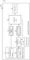
- Fig. 1 shows a block diagram of the configuration example of deep body thermometer according to the present embodiment.
- the deep body thermometer 100 comprises a measurement part 1, a power source 2, a switching part 3, a temperature-signal processing part 4, a heat-flux signal processing part 5, a controller part 6, and an output part 7.
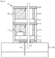
- Fig. 2 shows a cross-sectional view illustrating the configuration example of measurement part according to the present embodiment.
- the measurement part 1 comprises, at the side of measuring face that contacts with the body surface of subject for measuring the deep body temperature and within a case 10 made from plastics, a substrate 11, a heat-diffusion layer 12, and a heatinsulation layer 13. Furthermore, the measurement part 1 comprises a heat collection plate 14 at the face of case 10 facing to the measuring surface side and a heat conduction sheet 15 at the face opposite thereto.
- the substrate 11 is made of materials having insulation performance such as, for example, polyimide and the like, and in the present embodiment, is a flexible substrate (film substrate) having flexibility and being formed as the plane plate of 8mm ⁇ 10mm.
- the substrate 11 should not be limited to the deformable flexible substrate and may also be a deformable printed circuit board.
- the substrate 11 is arranged with disposing a temperature sensor 111 and a thermo-electric element 112 in close proximity on the face opposite to the measuring face such that the temperature T measured by the temperature sensor 111 and the temperature T' at the lower face (measuring face side) of thermo-electric element 112 becomes approximately equal.
- a temperature sensor 111 and a thermo-electric element 112 in close proximity on the face opposite to the measuring face such that the temperature T measured by the temperature sensor 111 and the temperature T' at the lower face (measuring face side) of thermo-electric element 112 becomes approximately equal.
- the temperature sensor 111 is configured from, for example, thermistors such as a NTC (Negative Temperature Coefficient) thermistor of which resistance value changes depending on the temperature.
- the temperature sensor 111 measures the temperature T of the subject-body surface. According to the present embodiment, from the point of view for improving responsibility, a heat capacity is low as low as possible such that the chip NTC thermistor is used as the temperature sensor 111.
- the temperature sensor 111 is electrically connected with the controller part 6 via. printed wirings not shown and outputs electric signals (voltage value) indicating the measured temperature T via. printed wirings not shown.
- the thermo-electric element 112 is configured from for example, a Peltier element etc.
- the thermo-electric element 112 functions as a heat-flux sensor for obtaining the heat flux amount HF from deep positions such as subject's brain and organs etc.
- the thermo-electric element 112 is electrically connected with the controller part 6 via. printed wirings not shown and outputs the electric signals (voltage value) indicating the measured heat flux amount HF via. printed wirings not shown.
- the thermo-electric element 112 allows to flow direct currents when the electric power is supplied from the power source 2 to heat or cool the body surface of subject (by changing the temperature of object's surface to be measured) and also functions as a heat source for changing the heat flux amount HF from the deep positions.
- the heat-diffusion layer 12 is configured by carbon heat conduction sheets and the like for attaining efficient heat conduction such as graphite sheets or carbon sheets etc. having extremely high heat conductivity (for example, 1350 [W/mK] and the like).
- the heat diffusion layer 12 may be configured by metal thin films such as aluminum sheets or copper sheets.
- the heat diffusion layer 12 is disposed at the face of measuring surface side of substrate 11; diffuses the heat entered from a heat collection plate 14; and allows heat conduction to the direction horizontal to the measuring face such that temperature distribution within the face at the measuring surface of substrate 11 makes even.
- the heat diffusion layer 12 can make the temperature T measured by the temperature sensor 111 and the temperature T' at the lower face (measuring face side) of thermo-electric element 112 approximately equal.
- the temperature sensor 111 can measure the temperature of subject side face (lower surface) of thermo-electric element 112.
- the heat insulation layer 13 is configured from materials having heat insulating performance, for example, including an air layer not allowing air convection, polyimide, polyethylene foam and polyurethane foam and the like and is filled in the case 10 so as to cover the temperature sensor 111 and the thermo-electric element 112.
- the heat insulation layer 13 thermally insulates the temperature sensor 111 and the thermo-electric element 112 such that the heat becomes hard to escape to the direction parallel the measuring face while improving the measurement precisions of temperature sensor 111 and thermo-electric element 112.
- the heat collection plate 14 is configured from metal plates etc., for example, from pure copper etc. which have larger heat conductivity when compared with the subject.
- the heat collection plate 14 collects the heat on the subject's body surface and transfers to the temperature sensor 111 and to the thermo-electric element 112 via. the heat diffusion layer 12 to make it possible that the temperature sensor 111 and the thermo-electric element 112 can each measure the temperature T and the heat flux amount HF of subject's body surface over the case 10 made from plastics.
- the heat conduction sheet 15 is configured from metal thin films etc., for example aluminum sheets or copper foils having good heat conduction performance (for example, 3-4[W/mK] and the like.).
- the measurement part 1 is arranged with equipping the heat collection plate 14 and the heat conduction sheet 15 so as to generate the temperature difference between the face at the measuring face side of thermo-electric element 112 and the face at the opposite side thereto while allowing to promote heat transfer to the direction perpendicular the measuring face.
- the power source 2 shown in Fig. 1 is configured by batteries etc. for example, a primary battery or a secondary battery and the like for general purpose and supplies the electric power (for example, to the extent of not more than 0.5 W) to the thermo-electric element 112.
- the switching part 3 is configured from, for example, a general-purpose switching circuit etc.
- the switching part 3 switches the motion (mode) of thermo-electric element 112 under the control of controller 6.
- the switching part 3 when the thermo-electric element 112 is used as a heat flux sensor, electrically connects the thermo-electric elements 112 with the heat-flux signal processing part 5.
- the switching part 3 when the thermo-electric element 112 is used as the heat source, electrically connects the thermo-electric element 112 with the power source 2.
- the temperature-signal processing part 4 and heat-flux signal processing part 5 are configured from general-purpose amplifiers and general-purpose A/D (Analog-to-digital) converters (ADC) etc.
- the temperature-signal processing part 4 amplifies analog electric signals input from the temperature sensor 111; then converts to digital electric signals; and outputs them.
- the heat-flux signal processing part 5 amplifies analog electric signals input from the thermo-electric element 112; then converts to digital electric signals; and outputs them.
- the controller part 6 is configured from, for example, MCU (Micro Control Unit), ROM (Read Only Memory) and RAM (Random Access Memory) etc.
- MCU uses RAM as a working memory and executes adequately various programs etc. stored in ROM to control the various motions of deep body thermometer 100.
- the controller part 6 measures the deep body temperature of subject based on the temperature T indicated by the electric signals input from the temperature-signal processing part 4 and the heat flux amount HF indicated by the electric signals input from the heat-flux signal processing part 5.
- thermo-electric element 112 since the temperature T measured by the temperature sensor 111 and the temperature T' at the lower face (measuring face side) of thermo-electric element 112 are approximately equal, the temperature T indicated by the electric signals input from the temperature-signal processing part 4 is treated as to indicate the temperature T' at the lower face (measuring face side) of thermo-electric element 112.
- the controller part 6 outputs a first control signal for instructing electric connection between the thermo-electric element 112 and the heat-flux signal processing part 5 to the switching part 3 to make the thermo-electric element 112 function as the heat flux sensor.
- the controller part 6 obtains the temperature T ( ⁇ T') indicated by the electric signal input from the temperature-signal processing part 4 and the heat flus amount HF indicated by the electric signal input from the heat-flux signal processing part 5 as the temperature T1 and the heat flux HF1 of subject at the normal condition before heating or cooling the body surface of subj ect.
- T1 and heat flux amount HF 1 obtained under the normal condition, the following relation (1) is satisfied.
- Ti ⁇ T 1 / Rz HF 1
- Ti is the deep body temperature
- Rz is the thermal resistance value of subject's subcutaneous tissue 130, which are unknown values, respectively.
- the controller part 6 outputs to the switching part 3 a second control signal for instructing electric connection between the thermo-electric element 112 and the power source 2 to make the thermo-electric element 112 function as the heat source.
- the controller part 6 changes the temperature of subject's surface by supplying the electric power to the thermo-electric element 112.
- the controller part 6 obtains the temperature T ( ⁇ T') indicated by the electric signal input from the temperature-signal processing part 4 and the heat flux amount HF indicated by the electric signal input from the heat-flux signal processing part 5.
- the controller 6 obtains the deep body temperature of subject Ti by substituting into the equation (3) the temperature T1 and the heat flux amount HF1 obtained at the normal condition together with the temperature T2 and the heat flux amount HF2 obtained at the thermal equilibrium condition.
- the controller part 6 displays the obtained deep body temperature on the display screen of output part 7 to acknowledge the deep body temperature Ti to the subject.
- the controller part 6 may determine whether or not the subject has the fear of thermic fever from the transition of deep body temperatures. Furthermore, the controller part 6, if a predetermined condition is satisfied such as the case where the deep body temperature exceeds a predetermined threshold value (dangerous value) or the case where the change in the deep body temperature exceeds a predetermined range, determines that there is the fear of thermic fever and may display on the display screen of output part 7; may generate alarm sounds from a speaker; and may light on or flash LED to acknowledge the subject for the fear of thermic fever.
- a predetermined condition such as the case where the deep body temperature exceeds a predetermined threshold value (dangerous value) or the case where the change in the deep body temperature exceeds a predetermined range
- the output part 7 can be configured from, for example, a liquid crystal display device etc. for general purpose.
- the output part 7 displays on the display screen the deep body temperature Ti which the controller part 6 has obtained.
- the output part 7 is configured from a non-volatile memory etc. for general-purpose, for example, from a flash memory and the like and from one that stores the deep body temperature Ti that the controller part 6 has obtained.
- the output part 7 may be configured from, for example, a wireless transmission device etc. for general-purpose and may be one that the deep body temperature Ti obtained by the controller part 6 is transmitted to an outside server computer through a network such as INTERNET and the like.
- the output part 7 may be one that are combined with a liquid crystal display device for general-purpose, a non-volatile memory for general-purpose and a wireless transmission device for general-purpose.
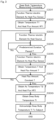
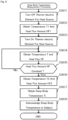
- Fig. 3 is a flowchart illustrating the detail of deep body temperature measurement processing of the present embodiment.
- the controller part 6 of deep body thermometer 100 first outputs to the switching part 3 a first control signal for instructing the electric connection between the thermo-electric element 112 and the heat-flux signal processing part 5 to make the thermo-electric element 112 function as the heat flux sensor (Step S301).
- the controller part 6 obtains the temperature T ( ⁇ T') indicated by the electric signal input from the temperature-signal processing part 4 and the heat flus amount HF indicated by the electric signal input from the heat-flux signal processing part 5 as the temperature T1 and the heat flux HF1 of subject at the normal condition before heating or cooling the body surface of subject (Step S302).
- the controller part 6 outputs to the switching part 3 a second control signal for instructing electric connection between the thermo-electric element 112 and the power source 2 to make the thermo-electric element 112 function as the heat source (Step S303).
- Step S304 determines whether or not the predetermined duration has passed after the thermo-electric element 112 has been made to function as the heat source (Step S304), and if not having passed (Step S304; No), loops to wait.
- the controller part 6 outputs, when the predetermined duration has passed (Step S304; Yes), the first control signal to the switching part 3 and makes the thermo-electric element 112 function again as the heat flux sensor (Step S305).
- the controller part 6 obtains the temperature T ( ⁇ T') indicated by the electric signal input from the temperature-signal processing part 4 and the heat flus amount HF indicated by the electric signal input from the heat-flux signal processing part 5 (Step S306).
- Step S306 determines whether or not the heat flux amount HF obtained in Step S306 becomes constant (Step S307), and if not becoming constant (Step S307; No), returns to Step S303 to obtain the temperature T and the heat flux amount HF again after the predetermined duration has passed.
- Step S306 when the heat flux HF obtained in Step S306 becomes constant (Step S307; Yes), obtains the temperature T ( ⁇ T') indicated by the electric signal input from the temperature-signal processing part 4 and the heat flus amount HF indicated by the electric signal input from the heat-flux signal processing part 5 as the temperature T2 and the heat flux HF2 of subject at the thermal equilibrium condition (Step S308).
- the controller part 6 obtains (measures) the deep body temperature of subject Ti by substituting into the equation (3) the temperature T1 and the heat flux amount HF1 obtained at the normal condition together with the temperature T2 and the heat flux amount HF2 obtained at the thermal equilibrium condition (Step S309).
- the controller part 6 displays the obtained deep body temperature Ti in Step S309 on the display screen of output part 7 so as to acknowledge the deep body temperature Ti to the subject (Step S310) and terminates the deep body temperature measurement processing.
- the deep body thermometer (internal temperature measurement device) 100 of the present invention comprises the measurement part 1 and the controller part 6.
- the measurement part 1 comprises the thermo-electric element 112 for measuring the heat flux HF from the inside of subject as the object for the measurement and the temperature sensor 111 for measuring the temperature T at the subject' side face of thermo-electric element 112.
- the measurement part 1 outputs the heat flux amount HF 1 measured by the thermo-electric element 112, the temperature T1 measured by the temperature sensor 111 at the heat flux amount HF1, the heat flux amount HF2 different from the heat flux amount HF1 measured by the thermo-electric element 112, and the temperature T2 that the temperature sensor 111 has measured at the heat flux amount HF2.
- the controller part 6 obtains the deep body temperature Ti of subject based on the heat flux amount HF1, the temperature T1, the heat flux amount HF2, and the temperature T2 input from the measurement part 1.
- the controller part 6 obtains the heat flux amount HF1 and the temperature T1 from the measurement part 1. Next, the controller part 6 obtains, after changing the temperature of subject's surface by supplying the electric power to the thermo-electric element 112, the heat flux HF2 and the temperature T2 from the measurement part 1. In more detail, the controller part 6, after supplying the electric power for the predetermined duration to the thermo-electric element 112, determines whether or not the heat flux HF input from the measurement part 1 becomes constant. The controller part 6, if the heat flux amount HF is determined to become constant, obtains the heat flux amount HF and the temperature T input from the measurement part 1 as the heat flux amount HF2 and the temperature T2. Then, the controller part 6 obtains the deep body temperature Ti of subject based on the heat flux amount HF1, the temperature T1, the heat flux amount HF2 and the temperature T2.
- the deep body thermometer 100 without providing the heat flux sensor having high-cost sandwich structure, can realize the approximately same function as the heat flux sensor having the sandwich structure by the temperature sensor 111 and the thermo-electric element 112 such that the deep body thermometer 100 can be manufactured in lower cost than conventional one.
- the description has been presented as one that the temperature sensor 111 and the heat flux sensor 112 are positioned in close proximity on the face opposite to the measuring face of substrate 11; however, the present invention should not be limited thereto.
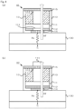
- Fig. 4(a) shows the cross-sectional view of configuration example for the measurement part according to the modified embodiment 1.
- the temperature sensor 111 is disposed at the lower face (face at the measuring side face) of thermo-electric element 112 and may be one that measures the temperature of lower face (face at the measuring side face) of thermo-electric element 112.
- Fig. 4 (b) shows the cross-sectional view of configuration example for the measurement part according to the modified embodiment 2.
- the temperature sensor 111 may be disposed at the upper face (face at the side opposite to the measuring face) of heat conduction sheet 15 placed above the thermo-electric element 112.
- the measurement part 1 has been described as one that the measurement part 1 comprises one temperature sensor 111 and one heat flux sensor 112, respectively; however, the present invention should not be limited thereto.
- Fig. 5 shows a block diagram illustrating the entire configuration of deep body thermometer according to modified embodiment 3.
- the deep body thermometer 500 comprises first and second measurement parts 51 and 52, first and second temperature-signal processing parts 53 and 54, first and second heat-flux signal processing parts 55 and 56, the controller part 6 and the output part 7.
- Fig. 6 shows the cross-sectional view of configuration example according to the modified embodiment 3.
- the substrate 11 of first measurement part 51 is arranged with providing a first temperature sensor 611 and a first thermo-electronic element 621 in close proximity on the face opposite to the measuring face such that the temperature T1 measured by the first temperature sensor 611 and the temperature T 1' at the lower face (measuring side face) of first thermo-electric element 621 becomes approximately equal.
- the first temperature sensor 611 is connected with the controller part 6 via. printed wirings not shown and outputs electric signals (voltage value) indicating the measured temperature T1 via. printed wirings not shown.
- the first thermo-electric element 621 is connected with the controller part 6 via. printed wirings not shown and outputs electric signals (voltage value) indicating the measured heat flux amount HF1 via. printed wirings not shown.
- the substrate 11 of second measurement part 52 is arranged with providing a second temperature sensor 612 and a first thermo-electronic element 622 in close proximity on the face opposite to the measuring face side such that the temperature T2 measured by the second temperature sensor 612 and the temperature T2' at the lower face (measuring face side) of second thermo-electric element 622 becomes approximately equal.
- the second thermo-electric element 612 is connected with the controller part 6 via. printed wirings not shown and outputs electric signals (voltage value) indicating the measured temperature T2 via. printed wirings not shown.
- thermo-electric element 622 since the second thermo-electric element 622 has the different thermal resistance from the first thermo-electric element 621 such that the second thermo-electric element 622 measures the heat flux HF2 different from the heat flux HF1 that has been measured by the first thermo-electric element 621.
- the second thermo-electric element 622 connected with the controller part 6 via. printed wirings not shown and outputs electric signals (voltage value) indicating the measured heat flux amount HF2 via. printed wirings not shown.
- the heat diffusion layer 12 is disposed on the face at the measuring face side of substrate 11 and diffuses the heat entered from the heat collection plate 14; thermally transfers to the direction horizontal to the measuring face; and makes the temperature distribution of substrate 11 within the face at the measuring side even.
- the heat diffusion payer 12 can make the temperature T1 measured by the first temperature sensor 611 and the temperature T 1' at the lower face (measuring fade side) of first thermo-electric element 621 approximately equal.
- the first temperature sensor 611 can measure the temperature at the subject side face (lower face) of first thermo-electric element 621.
- the heat diffusion layer 12 can make the temperature T2 measured by the second temperature sensor 612 and the temperature T2' at the lower side (measuring side face) of second thermo-electric element 622 even.
- the second temperature sensor 612 can measure the temperature at the subject side face (lower face) of second thermo-electric element 622.
- the first temperature-signal processing part 53 shown in Fig. 5 amplifies the analog electric signals input from the first temperature sensor 611; then converts into the digital electric signals; and outputs them.
- the second temperature-signal processing part 54 amplifies the analog electric signals input from the second temperature sensor 612; then converts into the digital electric signals; and outputs them.
- the first heat-flux signal processing part 55 amplifies the analog electric signals input from the first thermo-electric element 621; then converts into the digital electric signals; and outputs them.
- the second heat-flux signal processing part 56 amplifies the analog electric signals input from the second thermo-electric element 622; then converts into the digital electric signals; and outputs them.
- the controller part 6 may obtain the deep body temperature Ti of subject by substituting into Equation (3) the temperature T1 ( ⁇ T1') and the heat flux amount HF1, measured by the first measurement part 51 and the temperature T2 ( ⁇ T2') and the heat flux amount HF2 measured by the second measurement part 52.
- the measurement part comprises the first measurement part 51 and the second measurement part 52.
- the first measurement part 51 comprises the first thermo-electric element 621 and the first temperature sensor 611 that measures the temperature of the subject side face of first thermo-electric element 621. Furthermore, the first measurement part 51 outputs the heat flux amount HF1 measured by the first thermo-electric element 621 and the first temperature T1 measured by the first temperature sensor 611.
- the second measurement part 52 comprises the second thermo-electric element 622 that has the thermal resistance value different from the first thermo-electric element 621 and the second temperature sensor 612 that measures the temperature of the subject side face of second thermo-electric element 622. Furthermore, the measurement part 52 outputs the heat flux amount HF2 measured by the second thermo-electric element 622 and the second temperature T2 measured by the second temperature sensor 612.
- the deep body thermometer 500 without providing the heat flux sensor having high-cost sandwich structure, can realize the approximately same function as the heat flux sensor having the sandwich structure by using the first and the second temperature sensors 611 and 612 together with the first and the second thermo-electric elements 621 and 622 such that the deep body thermometer 500 can be manufactured in lower cost than conventional one.
- the first and the second temperature sensors 611 and 621 may be disposed at the lower face (face at the measuring face side face) of first and second thermo-electric elements 612 and 622.
- the first and the second temperature sensors 611 and 621 may be each disposed to the upper face (face opposite to the measuring face) of the heat conduction sheet 15 of first and second thermo-electric elements 612 and 622.
- modified embodiment 4 which comprises two thermo-electric elements each having different rolls such as the thermo-electric element that measures the heat flux of subject and the thermo-electric element that is used as the heat source.
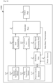
- Fig. 7 shows the block diagram illustrating the entire configuration of deep body thermometer according to the modified embodiment 4.
- the deep body thermometer 700 comprises a measurement part 71, the power source 2, the temperature-signal processing part 4, the heat-flux signal processing part 5, the controller part 6 and the output part 7.
- Fig. 8 shows a cross-sectional view illustrating the configuration example of measurement part according to the modified embodiment 4.
- the substrate 11 of measurement part 71 is arranged with disposing a temperature sensor 111 and a thermo-electric element 821 for measurements in close proximity on the face opposite to the measuring face such that the temperature T that is measured by the temperature sensor 111 and the temperature T' at the lower face (measuring face side) of thermo-electric element 821 for measurements becomes approximately equal.
- the substrate 81 is disposed on the upper face of heat conduction sheet 15 (face opposite to the measuring face).
- the substrate 81 is arranged with disposing a thermo-electric element 822 for heat source on the face opposite to the measuring face at the position corresponding to the thermo-electric element 821. That is, the measurement part 71 according to the modified embodiment 4 comprises two thermo-electric elements each having different rolls such as the thermo-electric element 821 for measuring the heat flux of subject and the thermo-electric element 822 used as the heat source.
- the thermo-electric element 821 for measurement is one that functions as the heat flux sensor and obtains the heat flux amount HF from deep positions such as the brain or organs of subject.
- the thermo-electric element 821 for measurement is electrically connected with the controller part 6 via. printed wirings not shown and outputs electric signals (voltage value) indicating the measured heat flux amount HF via. printed wirings not shown.
- thermo-electric element 822 is one that functions as the heat source, and when the electric power is supplied from the power source 2, allows to flow direct currents so as to heat or cool the body surface of subject (to change the temperature of subject's surface) together with so as to change the heat flux amount from the deep position.
- the heat diffusion layer 12 is disposed on the face at the measuring face side of substrate 11 and diffuses the heat entered from the heat collection plate 14 and allows heat conduction to the direction horizontal to the measuring face such that temperature distribution within the face at the measuring surface of substrate 11 makes even. Thereby, the heat diffusion layer 12 can make the temperature T measured by the temperature sensor 111 and the temperature T' at the lower face (measuring face side) of thermo-electric element 821 for heat measurement approximately equal. As the result, the temperature sensor 111 can measure the temperature of the face at the subject's side (lower surface) of thermo-electric element 821 for measurement.
- the heat insulation layer 13 is filled in a case 80 for covering the thermo-electric element 822 for heat source.
- the heat conduction sheet 85 is disposed.
- the controller part 6 shown in Fig. 7 first turn off the power source 2 to terminate the thermo-electric element 822. Next, the controller part 6 obtains the temperature T ( ⁇ T') indicated by the electric signal input from the temperature-signal processing part 4 and the heat flux amount HF indicated by the electric signal input from the heat-flux signal processing part 5 as the temperature T1 and the heat flux HF1 of subject at the normal condition before heating or cooling the body surface of subject.
- the controller part 6 turns on the power source 2 to start the thermo-electric element 822 for heat source and obtains the temperature T indicated by the electric signals input from the temperature-signal processing part 5 and the heat flux amount HF indicated by the electric signals input from the heat-flux signal processing part 4. Furthermore, the controller part 6 determines whether or not the obtained heat flux amount HF becomes constant, and if becoming constant, obtains the temperature T ( ⁇ T') input from the temperature-signal processing unit 4 and the heat flux amount HF input from the heat-flux signal processing part 5 as the temperature T2 and the heat flux amount HF2 of subject at the equilibrium condition.
- the controller part 6 may obtain the deep body temperature Ti of subject by substituting into the equation (3) the temperature T1 and the heat flux amount HF1 obtained at the normal condition together with the temperature T2 and the heat flux amount HF2 obtained at the thermal equilibrium condition.
- Fig. 9 shows a flowchart illustrating the detail of deep body temperature measuring processing according to the modified embodiment 4.
- the controller part 6 of deep body thermometer 700 first turns off the electric power 2 to terminate the thermo-electric element 822 for heat source (Step S901).
- the controller part 6 obtains the temperature T ( ⁇ T') indicated by the electric signal input from the temperature-signal processing part 4 and the heat flus amount HF indicated by the electric signal input from the heat-flux signal processing part 5 as the temperature T1 and the heat flux HF 1 of subject at the normal condition before heating or cooling the body surface of subject (Step S902).
- the controller part 6 turns on the power source 2 to start the thermo-electric element 822 for heat source (Step S903) and obtains the temperature T ( ⁇ T') indicated by the electric signals input from the temperature-signal processing part 4 and the heat flux amount HF indicated by the electric signals input from the heat-flux signal processing part 5 (Step S904).
- Step S905 determines whether or not the heat flux amount HF obtained in Step S904 becomes constant (Step S905), and if not becoming constant (Step S905; No), returns to Step S904 to obtain the temperature T ( ⁇ T') and the heat flux amount HF again and determines whether or not the heat flux amount HF becomes constant.
- Step S905 when the heat flux HF obtained in Step S904 becomes constant (Step S905; Yes), obtains the temperature T ( ⁇ T') indicated by the electric signal input from the temperature-signal processing part 4 and the heat flus amount HF indicated by the electric signal input from the heat-flux signal processing part 5 as the temperature T2 and the heat flux HF2 of subject at the thermal equilibrium condition (Step S906).
- the controller part 6 obtains (measures) the deep body temperature Ti of subject by substituting into the equation (3) the temperature T1 and the heat flux amount HF1 obtained at the normal condition together with the temperature T2 and the heat flux amount HF2 obtained at the thermal equilibrium condition (Step S907).
- the controller part 6 displays the obtained deep body temperature in Step S907 on the display screen of output part 7 to acknowledge the deep body temperature Ti to the subject (Step S908) and terminates the deep body temperature Ti measurement processing.
- the measurement part 71 further comprises the thermo-electric element 822 for heat source, which is used as the heat source.
- the controller part 6 obtains the heat flux amount HF1 measured by the thermo-electric element 821 for measurement and the temperature T1 measured by the temperature sensor 111. Then, the controller part 6, after changing the temperature of subject's surface by supplying the electric power to the thermo-electric element 822 for heat source, obtains the heat flux HF2 measured by the thermo-electric element 821 and the temperature T2 measured by the temperature sensor 111.
- the deep body thermometer 1 without providing the heat flux sensor having high-cost sandwich structure, can realize the approximately same function as the heat flux sensor having the sandwich structure by using the temperature sensor 111 and the thermo-electric element 112 such that the deep body thermometer can be manufactured in lower cost than conventional one.
- the temperature sensor 111 may be disposed at the lower face (face at the measuring face side) of thermo-electric element 821 for measurement. Furthermore, as the measuring part 42 according to the modified embodiment 2, the temperature sensor 111 may be disposed at the upper face (face opposite to the measuring face) of heat conduction sheet 85 placed above the thermo-electric element 821 for measurement.
- thermo-electric element which two temperature sensors and a thermo-electric element are each disposed at equal spacings.
- Fig. 10 shows a block diagram illustrating the entire configuration of deep body thermometer according to modified embodiment 5.
- the deep body thermometer 1000 comprises a measurement part 101, the power source 2, the switching part 3, first and second temperature-signal processing parts 53 and 54, the heat-flux signal processing part 5, the controller part 6, and the output part 7.
- Fig. 11 shows a cross-sectional view illustrating the configuration example of measurement part according to the modified embodiment 5.
- the substrate 11 of measurement part 101 is arranged with disposing a second temperature sensor 612, a first temperature sensor 611 and a thermo-electric element 112 with approximately equal spacings and in close proximity on the face opposite to the measuring face such that the temperature T" measured by the second temperature sensor 612, the temperature T measured by the first temperature sensor 611 and the temperature T' at the lower face (measuring face side) of thermo-electric element 112 becomes approximately equal.
- the first temperature sensor 611 is electrically connected with the controller part 6 via. printed wirings not shown and outputs electric signals (voltage value) indicating the measured temperature T via. printed wirings not shown.
- the second temperature sensor 612 is electrically connected with the controller part 6 via. printed wirings not shown and outputs electric signals (voltage value) indicating the measured temperature T" via. printed wirings not shown.
- the heat diffusion layer 12 diffuses the heat entered from the heat collection plate 14; thermally transfers to the direction horizontal to the measuring face; and makes the temperature distribution of substrate 11 within the face at the measuring side. Thereby, the heat diffusion layer 12 can make the temperature T" measured by the second temperature sensor 612, the temperature T measured by the first temperature sensor 611 and the temperature T' at the lower face (measuring face side) of thermo-electric element 112 approximately equal. As the result, the first and second temperature sensors 611 and 612 can measure the temperature of the subject' side face (lower face) of thermo-electric element 112.
- the first temperature-signal processing part 53 shown in Fig. 10 amplifies analog electric signals input from the first temperature sensor 611; then converts to digital electric signals; and outputs them.
- the second temperature-signal processing part 54 amplifies analog electric signals input from the second temperature sensor 612; then converts to digital electric signals; and outputs them.
- the controller part 6 determines whether or not the temperature T input from the first temperature-signal processing unit 53 becomes approximately equal to the temperature T" input from the second temperature-signal processing part 54.
- the controller part 6, when the temperature T is approximately equal to the temperature T" determines that the temperature T' of the lower face (measuring face side) of thermo-electric element 112 is also approximately equal to the temperature T and T" and obtains the temperature T (or T") as one that indicates the temperature T' at the lower face (measuring face side) of thermo-electric element 112.
- thermo-electric element 112 when the temperature T is not approximately equal to the temperature T", since the second temperature sensor 612, the first temperature sensor 611 and the thermo-electric element 112 are disposed in the approximately equal spacings, the difference (T-T") between the temperature T measured by the first temperature sensor 611 and the temperature T" measured by the second temperature sensor 115 and the difference (T'-T) between the temperature T' at the lower face (measuring face side) of thermo-electric element 112 and the temperature T measured by the first temperature sensor 111 become approximately equal and satisfies the following equation (4).
- T ⁇ T " T ′ ⁇ T
- thermo-electric element 112 the temperature T' at the lower face (measuring face side) of thermo-electric element 112 is represented by the following equation (5).
- T ′ 2 T ⁇ T "
- the temperature sensor comprises the first temperature sensor 611 and the second temperature sensor 612.
- the measurement part 101 is arranged with equipping the second temperature sensor 612, the first temperature sensor 611 and thermo-electric element 112 in approximately equal spacings.
- the controller part 6 when the temperature measured by the second temperature sensor 612 is approximately same with the temperature measured by the first temperature sensor 611, obtains the temperature measured by the first temperature sensor 611 as the temperature of the thermo-electric element 112 at the subject's side face.
- the controller part 6 when the temperature measured by the second temperature sensor 612 is not approximately same with the temperature measured by the first temperature sensor 611, obtains the temperature of the thermo-electric element 112 at the subject's side face from the difference between the temperature measured by the second temperature sensor 612 and the temperature measured by the first temperature sensor 611 and the temperature measured by the first temperature sensor 611.
- the deep body thermometer 1000 without providing the heat flux sensor having high-cost sandwich structure, can realize the approximately same function as the heat flux sensor having the sandwich structure by the first and second temperature sensors 611 and 612 as well as the thermo-electric element 112 such that the deep body thermometer 1000 can be manufactured in lower cost than conventional one. Furthermore, the deep body thermometer 1000, by arranging the second temperature sensor 612, the first temperature sensor 611 and the thermo-electric element 112 in approximately equal spacings, can measure the temperature of thermo-electric element 112 at the lower face (measuring face side), that is, the deep body temperature Ti more precisely.
- the configuration, to which two temperature sensors and the thermo-electric element are each disposed in the same spacings, may be applicable to the deep body thermometers 500 and 700 according to the modified embodiments 3 and 4 as well as the deep body thermometer 100 according to the present embodiment.
- the object to be measured is a subject, that is, a human being; however, the present invention should not be limited thereto, the object to be measured may be animals.
- the measurement part 1 has been explained as one that measures the deep body temperature by contacting with the body surface of subject.
- the present invention should not be limited thereto, one that measures the deep body temperature without contacting (contactless) with the body surface of subject may be contemplated.
- the deep body thermometer 100, 500, 700 and 1000 has been described as ones that issue a predetermined alarm for the fear of heat fever when the deep body temperature of subject satisfies a predetermined condition.
- the present invention should not be limited thereto, one that issues the alarm of fear for an emergency to mind and body other than the heat fever, when the deep body temperature of subject satisfies a predetermined condition, may be contemplated; any emergency of mind and body relating to the deep body temperature may be contemplated, and for example, hypothermia, quality of sleep, basal body temperature, immunity, stress may be included.
- the internal temperature measurement device 100, 500, 700, 1000 the deep body temperature for measuring the deep body temperature Ti has been exemplarily described.
- the internal temperature measurement device according to the present invention should not be limited thereto, one that analyze electric circuits by sending pulsed signals or alternative signals may be contemplated.
- one that measures the compositions of human body by impedance (resistance value under alternative signal) may be contemplated.
- one that performs the analysis of physical properties such as measuring water content by generating thermal pulses may be contemplated.
- the deep body thermometer 100, 500, 700 and 1000 which is equipped on the body surface such as the head or the trunk of body and measures the deep body temperature Ti that is the body temperature at the deep position such as brain or organs, have been exemplarily described.
- the internal temperature measurement device according to the present invention should not be limited thereto, one that is equipped to other than the trunk of body so as to estimate (including inference etc.) the internal body temperature may be contemplated.
- the internal body thermometer may be one that measures the internal body temperature at peripheral positions by equipping to the peripheral positions distal from the trunk of body such as the arm or the ankle etc. of subject so as to estimate (also including inference) the internal temperature at the peripheral positions may be contemplated.
- the controller part 6 may estimate the deep body temperature Ti from the internal temperature of subject at the peripheral positions. Particularly, internal body temperatures and deep body temperatures of subjects have been measured beforehand to obtain correlations between them and these may be stored in the controller part 6. Then, the controller part 6 may estimate the deep body temperature Ti from measured internal body temperature of subject at the peripheral position using the correlations obtained beforehand. For example, in the case where the correlation that the deep body temperature Ti is approximately higher by 5 °C than the internal body temperature of peripheral positions has been obtained, if the measured internal body temperature of subject's peripheral position is 32 °C, 37 °C may be estimated by adding the constant of 5 °C. In addition, the controller part 6 may issue the alarm of heat fever to the subject when the predetermined condition is satisfied such as the case where the estimated deep body temperature exceeds the predetermined threshold and the like.
- the program that the CPU of controller part 6 executes has been described as one stored in ROM beforehand; however, the present invention should not be limited thereto, the program for executing the above processings may be implemented to an existing and general-purpose computer for functioning as the deep body thermometer 100, 500, 700 and 1000 according to the present embodiments.
- Methods for distributing such program may be optional and may include, for example, distributing by storing in a computer readable storage medium (flexible disk, CD (Compact Disc)-ROM, DVD (Digital Versatile Disc)-ROM and/or providing by allowing download of the program stored in storage on a network such as INTERNET etc.
- a computer readable storage medium flexible disk, CD (Compact Disc)-ROM, DVD (Digital Versatile Disc)-ROM and/or providing by allowing download of the program stored in storage on a network such as INTERNET etc.
- the above processing is executed by sharing between OS (Operating System) and an application program or by collaboration of OS and the application program
- only the application program can be stored in the storage medium or the storage.
- delivery through the network by overlaying the program on carrier waves may be allowed.
- the program may be posted on a board on the network (BBS: Bulletin Board System) and may be distributed through the network.
- BBS Bulletin Board System
- the configuration may be allowed to start and to make the program execute likely to other application programs under the control of OS so as to allow the above processing to be able to execute.
Landscapes
- Physics & Mathematics (AREA)
- General Physics & Mathematics (AREA)
- Engineering & Computer Science (AREA)
- Health & Medical Sciences (AREA)
- Life Sciences & Earth Sciences (AREA)
- Chemical & Material Sciences (AREA)
- Combustion & Propulsion (AREA)
- Nonlinear Science (AREA)
- Biomedical Technology (AREA)
- Pathology (AREA)
- Biophysics (AREA)
- Heart & Thoracic Surgery (AREA)
- Medical Informatics (AREA)
- Molecular Biology (AREA)
- Surgery (AREA)
- Animal Behavior & Ethology (AREA)
- General Health & Medical Sciences (AREA)
- Public Health (AREA)
- Veterinary Medicine (AREA)
- Measuring And Recording Apparatus For Diagnosis (AREA)
- Measuring Temperature Or Quantity Of Heat (AREA)
Applications Claiming Priority (1)
| Application Number | Priority Date | Filing Date | Title |
|---|---|---|---|
| PCT/JP2022/007428 WO2023162054A1 (ja) | 2022-02-22 | 2022-02-22 | 内部温度測定装置、内部温度測定方法、及びプログラム |
Publications (2)
| Publication Number | Publication Date |
|---|---|
| EP4483789A1 true EP4483789A1 (de) | 2025-01-01 |
| EP4483789A4 EP4483789A4 (de) | 2025-12-31 |
Family
ID=82929853
Family Applications (1)
| Application Number | Title | Priority Date | Filing Date |
|---|---|---|---|
| EP22928585.3A Pending EP4483789A4 (de) | 2022-02-22 | 2022-02-22 | Vorrichtung zur messung der innentemperatur, verfahren zur messung der innentemperatur und programm dafür |
Country Status (4)
| Country | Link |
|---|---|
| US (1) | US20250164323A1 (de) |
| EP (1) | EP4483789A4 (de) |
| JP (2) | JP7122056B1 (de) |
| WO (1) | WO2023162054A1 (de) |
Families Citing this family (1)
| Publication number | Priority date | Publication date | Assignee | Title |
|---|---|---|---|---|
| EP4407286A1 (de) * | 2024-06-03 | 2024-07-31 | Melexis Technologies NV | Wärmeflusssensorvorrichtung und verfahren zur herstellung davon |
Family Cites Families (6)
| Publication number | Priority date | Publication date | Assignee | Title |
|---|---|---|---|---|
| JP2007212407A (ja) | 2006-02-13 | 2007-08-23 | Kanazawa Univ | 非加熱型深部体温計およびそれを用いた深部体温測定装置 |
| EP2387705B1 (de) * | 2009-01-19 | 2016-12-14 | Koninklijke Philips N.V. | Null-wärmeflusssensor und verwendungsverfahren |
| WO2017198788A1 (en) * | 2016-05-18 | 2017-11-23 | Koninklijke Philips N.V. | Single heat flux sensor arrangement |
| JP2018044804A (ja) * | 2016-09-13 | 2018-03-22 | 株式会社フジクラ | デバイス |
| WO2020184511A1 (ja) * | 2019-03-14 | 2020-09-17 | Biodata Bank株式会社 | 温度センサユニット及び体内温度計 |
| JP7151607B2 (ja) * | 2019-04-19 | 2022-10-12 | 日本電信電話株式会社 | 温度測定装置および温度測定方法 |
-
2022
- 2022-02-22 US US18/840,284 patent/US20250164323A1/en active Pending
- 2022-02-22 JP JP2022530851A patent/JP7122056B1/ja active Active
- 2022-02-22 WO PCT/JP2022/007428 patent/WO2023162054A1/ja not_active Ceased
- 2022-02-22 EP EP22928585.3A patent/EP4483789A4/de active Pending
- 2022-08-01 JP JP2022123012A patent/JP2023122518A/ja active Pending
Also Published As
| Publication number | Publication date |
|---|---|
| EP4483789A4 (de) | 2025-12-31 |
| US20250164323A1 (en) | 2025-05-22 |
| WO2023162054A1 (ja) | 2023-08-31 |
| JP2023122518A (ja) | 2023-09-01 |
| JPWO2023162054A1 (de) | 2023-08-31 |
| JP7122056B1 (ja) | 2022-08-19 |
Similar Documents
| Publication | Publication Date | Title |
|---|---|---|
| KR102830828B1 (ko) | 생체 데이터 측정 장치 | |
| US11744469B2 (en) | Thermal diffusion coefficient measuring device, and deep-body thermometer, deep-body temperature measuring device, and deep-body temperature measuring method using same | |
| EP2329240B1 (de) | Temperatursensorstruktur | |
| RU2678212C1 (ru) | Система и способ измерения температуры ядра тела | |
| JP2022532435A (ja) | 非侵襲的熱インタロゲーションのための装置、システム、及び方法 | |
| US7479116B2 (en) | Temperature measurement device | |
| CN104048771B (zh) | 温度测量装置及温度测量方法 | |
| US7059767B2 (en) | Electronic clinical thermometer | |
| JP3909301B2 (ja) | 身体温度情報端末装置及び身体温度情報処理システム | |
| US7981046B2 (en) | Temperature measurement device | |
| US20170311812A1 (en) | Battery thermal mass | |
| US12196622B2 (en) | Temperature measurement device and temperature measurement method | |
| JP2009080000A (ja) | 体温計 | |
| CN114235210B (zh) | 一种核心体温测量方法和装置 | |
| JP2008076144A (ja) | 電子温度計 | |
| JPS6358223A (ja) | 体温計測装置 | |
| EP4483789A1 (de) | Vorrichtung zur messung der innentemperatur, verfahren zur messung der innentemperatur und programm dafür | |
| Matsunaga et al. | Non-invasive and wearable thermometer for continuous monitoring of core body temperature under various convective conditions | |
| WO2025214522A2 (zh) | 探头组件、体温检测仪及体温检测系统 | |
| KR20230032212A (ko) | 체온 추정 장치 및 방법 | |
| US11974831B2 (en) | Apparatus and method for estimating body temperature | |
| Wagner et al. | Thermal testing and analysis of on-the-market smartwatches | |
| US20240272015A1 (en) | Sensing assembly | |
| WO2025241899A1 (zh) | 一种测温组件、可穿戴设备及测温方法 | |
| JP2019012027A (ja) | 生体データ測定装置 |
Legal Events
| Date | Code | Title | Description |
|---|---|---|---|
| STAA | Information on the status of an ep patent application or granted ep patent |
Free format text: STATUS: THE INTERNATIONAL PUBLICATION HAS BEEN MADE |
|
| PUAI | Public reference made under article 153(3) epc to a published international application that has entered the european phase |
Free format text: ORIGINAL CODE: 0009012 |
|
| STAA | Information on the status of an ep patent application or granted ep patent |
Free format text: STATUS: REQUEST FOR EXAMINATION WAS MADE |
|
| 17P | Request for examination filed |
Effective date: 20240903 |
|
| AK | Designated contracting states |
Kind code of ref document: A1 Designated state(s): AL AT BE BG CH CY CZ DE DK EE ES FI FR GB GR HR HU IE IS IT LI LT LU LV MC MK MT NL NO PL PT RO RS SE SI SK SM TR |
|
| DAV | Request for validation of the european patent (deleted) | ||
| DAX | Request for extension of the european patent (deleted) | ||
| A4 | Supplementary search report drawn up and despatched |
Effective date: 20251128 |
|
| RIC1 | Information provided on ipc code assigned before grant |
Ipc: A61B 5/01 20060101AFI20251124BHEP Ipc: G01K 13/20 20210101ALI20251124BHEP Ipc: G01K 1/16 20060101ALI20251124BHEP Ipc: G01K 7/42 20060101ALI20251124BHEP Ipc: G01K 17/00 20060101ALI20251124BHEP Ipc: A61B 5/00 20060101ALI20251124BHEP |