EP4481381A2 - Einwegsystem zur analyse der hämostatischen funktion - Google Patents
Einwegsystem zur analyse der hämostatischen funktion Download PDFInfo
- Publication number
- EP4481381A2 EP4481381A2 EP24197053.2A EP24197053A EP4481381A2 EP 4481381 A2 EP4481381 A2 EP 4481381A2 EP 24197053 A EP24197053 A EP 24197053A EP 4481381 A2 EP4481381 A2 EP 4481381A2
- Authority
- EP
- European Patent Office
- Prior art keywords
- sample
- chamber
- test
- reagents
- cartridge
- Prior art date
- Legal status (The legal status is an assumption and is not a legal conclusion. Google has not performed a legal analysis and makes no representation as to the accuracy of the status listed.)
- Pending
Links
Images


Classifications
-
- G—PHYSICS
- G01—MEASURING; TESTING
- G01N—INVESTIGATING OR ANALYSING MATERIALS BY DETERMINING THEIR CHEMICAL OR PHYSICAL PROPERTIES
- G01N29/00—Investigating or analysing materials by the use of ultrasonic, sonic or infrasonic waves; Visualisation of the interior of objects by transmitting ultrasonic or sonic waves through the object
- G01N29/02—Analysing fluids
-
- B—PERFORMING OPERATIONS; TRANSPORTING
- B01—PHYSICAL OR CHEMICAL PROCESSES OR APPARATUS IN GENERAL
- B01L—CHEMICAL OR PHYSICAL LABORATORY APPARATUS FOR GENERAL USE
- B01L3/00—Containers or dishes for laboratory use, e.g. laboratory glassware; Droppers
- B01L3/50—Containers for the purpose of retaining a material to be analysed, e.g. test tubes
- B01L3/502—Containers for the purpose of retaining a material to be analysed, e.g. test tubes with fluid transport, e.g. in multi-compartment structures
-
- G—PHYSICS
- G01—MEASURING; TESTING
- G01N—INVESTIGATING OR ANALYSING MATERIALS BY DETERMINING THEIR CHEMICAL OR PHYSICAL PROPERTIES
- G01N29/00—Investigating or analysing materials by the use of ultrasonic, sonic or infrasonic waves; Visualisation of the interior of objects by transmitting ultrasonic or sonic waves through the object
- G01N29/22—Details, e.g. general constructional or apparatus details
- G01N29/222—Constructional or flow details for analysing fluids
-
- G—PHYSICS
- G01—MEASURING; TESTING
- G01N—INVESTIGATING OR ANALYSING MATERIALS BY DETERMINING THEIR CHEMICAL OR PHYSICAL PROPERTIES
- G01N33/00—Investigating or analysing materials by specific methods not covered by groups G01N1/00 - G01N31/00
- G01N33/48—Biological material, e.g. blood, urine; Haemocytometers
- G01N33/483—Physical analysis of biological material
- G01N33/487—Physical analysis of biological material of liquid biological material
- G01N33/49—Blood
- G01N33/4905—Determining clotting time of blood
-
- G—PHYSICS
- G01—MEASURING; TESTING
- G01N—INVESTIGATING OR ANALYSING MATERIALS BY DETERMINING THEIR CHEMICAL OR PHYSICAL PROPERTIES
- G01N33/00—Investigating or analysing materials by specific methods not covered by groups G01N1/00 - G01N31/00
- G01N33/48—Biological material, e.g. blood, urine; Haemocytometers
- G01N33/50—Chemical analysis of biological material, e.g. blood, urine; Testing involving biospecific ligand binding methods; Immunological testing
- G01N33/86—Chemical analysis of biological material, e.g. blood, urine; Testing involving biospecific ligand binding methods; Immunological testing involving blood coagulating time or factors, or their receptors
-
- B—PERFORMING OPERATIONS; TRANSPORTING
- B01—PHYSICAL OR CHEMICAL PROCESSES OR APPARATUS IN GENERAL
- B01L—CHEMICAL OR PHYSICAL LABORATORY APPARATUS FOR GENERAL USE
- B01L2300/00—Additional constructional details
- B01L2300/08—Geometry, shape and general structure
- B01L2300/0809—Geometry, shape and general structure rectangular shaped
- B01L2300/0825—Test strips
-
- B—PERFORMING OPERATIONS; TRANSPORTING
- B01—PHYSICAL OR CHEMICAL PROCESSES OR APPARATUS IN GENERAL
- B01L—CHEMICAL OR PHYSICAL LABORATORY APPARATUS FOR GENERAL USE
- B01L2300/00—Additional constructional details
- B01L2300/08—Geometry, shape and general structure
- B01L2300/0832—Geometry, shape and general structure cylindrical, tube shaped
- B01L2300/0838—Capillaries
Definitions
- the present application relates to devices, systems and methods for evaluating hemostasis in a subject by preparation and analysis of a test sample from the subject.
- Hemostasis the physiological control of bleeding, is a complex process incorporating the vasculature, platelets, coagulation factors, fibrinolytic proteins, and a variety of activators and inhibitors. Disruption of hemostasis plays a central role in the onset of myocardial infarction, stroke, pulmonary embolism, deep vein thrombosis and excessive bleeding. Consequently, in vitro diagnostics (IVD) are critically needed to quantify hemostatic function/dysfunction and direct appropriate treatment.
- the process of coagulation is highly dependent, among other things, on the temperature at which it takes place. Under normal conditions, coagulation occurs at body temperature, which is optimal for the proper enzymatic action of the clotting factors in the cascade.
- Preparation of the blood to be tested is also important, as the manner a blood sample is prepared prior to its evaluation can affect, for example, the actions of the vasculature components, platelets and other cellular components, coagulation factors, fibrinolytic components, and any inhibitor or activator of hemostasis.
- the disposable system includes a multi-channel or multi-chamber test cartridge device configured to operate with a testing system for evaluation of hemostasis in a subject by in vitro evaluation of a test sample from the subject.
- the disposable system in some embodiments, is configured to interrogate the test sample to evaluate clot stiffness, strength, or other mechanical properties of the test sample to assess the function of various physiological processes occur during coagulation and/or dissolution of the resulting clot.
- the sample can include in whole, or in part, whole blood, plasma, platelet rich plasma, or platelet poor plasma.
- the sample can include one or more reagent (such as anticoagulants or anti-platelet drugs that might be present in the blood as collected), or one or more pharmacological treatment (such as in the case of heparin or low molecular weight heparin) or other inert components (such as polystyrene beads) that are added to the test sample before the cartridge device being used.
- reagent such as anticoagulants or anti-platelet drugs that might be present in the blood as collected
- pharmacological treatment such as in the case of heparin or low molecular weight heparin
- other inert components such as polystyrene beads
- the exemplified device automates one or more pre-measurement steps that minimizes sample manipulation steps required for the user, thereby improving test reproducibility and/or test quality.
- the disposable system in some embodiments, includes a plurality of testing circuits each having a pathway defined by channels and chambers configured to prepare a test sample of blood for evaluation by a measurement device. In each testing circuit, a portion of the test sample is introduced to a reagent or combination of reagents specific to that testing circuit.
- the disposable system in some embodiments, is configured to condition the respective test samples prior to, during, and/or after the mixing with the reagent(s), to optimize the proper actions of applicable blood component and chemistry (e.g., vasculature components, platelets or other cellular components, coagulation factors, fibrinolytic components, and any other inhibitor or activator of hemostatic function, etc.) being evaluated.
- applicable blood component and chemistry e.g., vasculature components, platelets or other cellular components, coagulation factors, fibrinolytic components, and any other inhibitor or activator of hemostatic function, etc.
- an apparatus for the assessment of hemostasis.
- the apparatus includes a housing; an input port integrally formed with the housing that is structurally configured to establish fluidic communication and evacuate contents of a sample holding tube; and a first chamber in fluidic communication with the input port, the first chamber being configured to receive a sample contained in the sample holding tube and to condition the received sample to a desired temperature (e.g., a pre-defined temperature range) before the received sample is allowed to contact one or more reagents located in one or more fluidic circuits downstream to the first chamber, wherein each of the one or more fluidic circuits comprises i) a second chamber in fluidic communication with the first chamber that meters the sample in the first chamber into an aliquot, wherein the metered sample is introduced to a reagent, or a combination of reagents, (e.g., in the form of lyophilized reagent bead) located in a corresponding fluidic circuit (e.g., a rea
- At least one of the one or more fluidic circuits comprise one or more pockets (e.g., each configured to house a lyophilized reagent bead comprising a reagent, or a combination of reagents).
- At least one of the one or more fluidic circuits comprise one or more liquid-retaining pockets (e.g., each configured to house an assay, in liquid form, comprising the reagent, or a combination of reagents).
- At least one of the one or more fluidic circuits includes one or more lyophilized reagents that are located on one or more surfaces thereof (e.g., lyophilized on each of the surfaces; lyophilized as films placed on, or adhered to, one or more of the surfaces).
- At least one of the one or more fluidic circuits includes one or more reagents that are processed onto surfaces thereof (e.g., dried on the surfaces; spray coated on the surfaces; baked onto the surfaces).
- the input port is communicatively coupled to a pressure port, wherein pressure applied to the pressure port causes the evacuation of the contents of the sample holding tube through the input port to first chamber.
- the input port comprises a needle assembly.
- the needle assembly comprises the input port and a second port, wherein the second port is configured to vent a liquid or gas into the sample holding tube so as to promote evacuation of the contents therein.
- the input port in some embodiments, is located (e.g., concentrically located) within a second port configured to vent a liquid or gas into the sample holding tube so as to cause evacuation of the contents of the sample holding tube.
- the input port comprises a luer lock configured to connect to the sample holding tube, wherein the sample holding tube is a syringe.
- the input port is communicatively coupled to a first pressure port, wherein pressure when applied to the first pressure port causes the evacuation of the contents of the sample holding tube through the input port to the first chamber.
- t he first chamber is configured to mate with a corresponding thermal regulating system (e.g., heating/cooling system) of the measurement system to condition the received sample to, or near, the desired temperature.
- a thermal regulating system e.g., heating/cooling system
- the shape and/or materials of the first chamber are optimized to facilitate thermal regulation (e.g., heating and/or cooling) of the sample to, or near, the desired temperature.
- the first chamber is configured to mate with a corresponding thermal regulating surface of a sub-system component of the measurement system to condition the received sample to, or near, the desired temperature.
- a channel portion of the one or more fluidic circuits is configured to mate with a corresponding heating/cooling system of the measurement system to condition the received sample to, or near, the desired temperature.
- a channel portion of the one or more fluidic circuits is configured to mate with a corresponding thermal regulating system of the measurement system to condition the received sample to the desired temperature.
- the first chamber and/or the channel portion of the one or more fluidic circuits is in physical proximity (e.g., physical contact or near contact) with a sensor configured to measure a temperature of the sample received in the first chamber.
- the senor is selected from group consisting of a thermistor, a thermocouple, and an optical sensor (e.g., an IR sensor).
- the apparatus includes a first pressure port in fluidic communication with the first chamber, the first pressure port being configured to receive negative or differential pressure (e.g., for filling the first chamber); and a filter positioned within the first pressure port in at least one of the fluidic circuits (e.g., such that the filter is clogged by the sample received in the first chamber when the first chamber is full).
- the filter in some embodiments, is configured to allow air to move through the first pressure port but prevent fluid from moving there through.
- the apparatus includes a first pressure port configured to receive negative or differential pressure for filling the first chamber; and a first fluidic pathway extending from the first pressure port to the first chamber, wherein the filter is positioned within the first pressure port.
- the fluidic communication between the first chamber and the second chamber is through a second fluid pathway originating from a side of the first chamber (e.g., a side wall, a bottom wall, and etc.) (e.g., such that bubbles present in the received sample are trapped away from the second chamber).
- a side of the first chamber e.g., a side wall, a bottom wall, and etc.
- each of the one or more fluidic circuits comprises a third fluid pathway in fluidic communication with the second chamber, wherein the third fluidic pathway leads a second pressure port configured receive negative or differential pressure for filling the second chamber.
- the second pressure port has a second filter therein, wherein the second filter is configured to clog when the second chamber is filled.
- the apparatus includes one or more fluidic pathways in fluidic communication with the second pressure port for all of the one or more fluidic circuits, wherein the one or more fluidic pathways are configured to provide the negative pressure to the second pressure port for all of the one or more fluidic circuits.
- the second chamber is in fluidic communication with a vent port, wherein the vent port is configured to be closed while the sample is metered into the aliquot in the second chamber and further configured to be open to atmospheric pressure after the sample is metered into the aliquot in the second chamber.
- each of the one or more fluidic circuits comprises a third set of fluid pathways in fluidic communication between a respective second chamber (e.g., metering chamber) and test chamber, wherein a portion of third set of fluid pathways are arranged as a serpentine-shaped conduit or channel.
- each of the one or more fluidic circuits further comprises a serpentine reservoir between the testing chamber and the second chamber.
- the metered sample is alternatively directed through portions of the one or more fluidic circuits to facilitate mixing of the metered sample and the reagent, or a combination of reagents.
- the metered sample is alternatively and multiplicatively directed, for each of the one or more fluidic circuits, between a first position (e.g., the second chamber) in a fluidic circuit a second position (e.g., a position in the serpentine reservoir) in the fluidic circuit.
- a first position e.g., the second chamber
- a second position e.g., a position in the serpentine reservoir
- each of the one or more fluidic circuits further comprises a third pressure port in fluidic communication with the second chamber and the testing chamber, the third pressure port configured to receive negative or differential pressure (e.g., for drawing the aliquot from the second chamber to the testing chamber), wherein the third pressure port is further configured to alternately receive alternating pressure, e.g., for alternately drawing the aliquot from the second chamber along the serpentine reservoir and pushing the aliquot through the serpentine reservoir to the second chamber.
- negative or differential pressure e.g., for drawing the aliquot from the second chamber to the testing chamber
- the third pressure port is further configured to alternately receive alternating pressure, e.g., for alternately drawing the aliquot from the second chamber along the serpentine reservoir and pushing the aliquot through the serpentine reservoir to the second chamber.
- the one or more quality testing portals is configured to be sensed electrically, wherein quality testing port comprises one or more sensing electrodes.
- the testing chamber comprises a mechanism to couple energy into the testing chamber to perform the measurements such as in the case of a lens configured to direct ultrasonic pulses into to the testing chamber.
- an apparatus for the assessment of hemostasis, the apparatus comprising: a housing; an input port integrally formed with the housing that is structurally capable of establishing fluidic communication with, and evacuating contents of, a sample holding tube; a first chamber that is in fluidic communication with the input port that receives the sample contained in the evacuated tube and whereby the sample temperature is adjusted to a desired temperature before the sample contacting one or more reagents; one or more second chambers that are in fluidic communication with the first chamber, the one or more second chamber being configured to meter the sample in the first chamber into one or more aliquots; one or more reagent pockets each filled with one or more lyophilized reagent bead that are in fluidic communication with each of the aliquot chambers and permits the sample present in each aliquot to be mixed with said one or more reagent beads; and one or more testing chambers that are in fluidic communications with the aliquot chambers and that are structurally capable of being interrogated to determine the sample viscoe
- t he reagent, or combination of reagents, located in the one or more fluidic circuits includes an intrinsic pathway activator (e.g., kaolin, celite, glass, ellagic acid, micronized silica, Hageman factor, etc.) or a combination therewith.
- an intrinsic pathway activator e.g., kaolin, celite, glass, ellagic acid, micronized silica, Hageman factor, etc.
- the reagent, or combination of reagents, located in the one or more fluidic circuits includes an extrinsic pathway activator (e.g., tissue factor, recombinant tissue factor, thromboplastin, etc.) or a combination therewith.
- extrinsic pathway activator e.g., tissue factor, recombinant tissue factor, thromboplastin, etc.
- the reagent, or combination of reagents, located in the one or more fluidic circuits includes a coagulation activator (e.g., thrombin, factor Xa, reptilase, ecarin, Russell's viper venom or other snake venoms, etc.) or a combination therewith.
- a coagulation activator e.g., thrombin, factor Xa, reptilase, ecarin, Russell's viper venom or other snake venoms, etc.
- the reagent, or combination of reagents, located in the one or more fluidic circuits includes a fibrinolytic functions activator or inhibitor (e.g., tPA, uKA, streptokinase, TAFIa, plasmin/plasminogen, aprotinin, epsilon-aminocaproic acid, tranexamic acid, plasminogen activator inhibitor 1 (PAIl), ⁇ 2-antiplasmin ( ⁇ 2-AP), or plasmin-antiplasmin complexes, carboxypeptidase inhibitor) or a combination therewith.
- a fibrinolytic functions activator or inhibitor e.g., tPA, uKA, streptokinase, TAFIa, plasmin/plasminogen, aprotinin, epsilon-aminocaproic acid, tranexamic acid, plasminogen activator inhibitor 1 (PAIl), ⁇ 2-antiplasmin ( ⁇ 2-AP), or plasmin-
- the reagent, or combination of reagents, located in the one or more fluidic circuits includes FXIIIa inhibitors or a combination therewith.
- the reagent, or combination of reagents, located in the one or more fluidic circuit includes thrombomodulin or a combination therewith. In some embodiments, the reagent, or combination of reagents, located in the one or more fluidic circuit includes low molecular weight heparin or a combination therewith.
- the reagent, or combination of reagents, located in the one or more fluidic circuits includes Hexadimethrine bromide (polybrene) or a combination therewith.
- the reagent, or combination of reagents, located in the one or more fluidic circuits includes heparin or a combination therewith.
- the reagent, or combination of reagents, located in the one or more fluidic circuits includes corn trypsin inhibitor or a combination therewith.
- the reagent, or combination of reagents, located in the one or more fluidic circuits includes adenosine or a combination therewith.
- the reagent, or combination of reagents, located in the one or more fluidic circuits includes GPRP (Gly-Pro-Arg-Pro) or a combination therewith.
- the reagent, or combination of reagents, located in the one or more fluidic circuits includes calcium or a combination therewith.
- the reagent, or combination of reagents, located in the one or more fluidic circuits includes fibronectin or a combination therewith.
- the reagent, or combination of reagents, located in the one or more fluidic circuits includes collagen or a combination therewith.
- the reagent, or combination of reagents, located in the one or more fluidic circuits includes an immuno-detection reagent or a combination therewith.
- the reagent, or combination of reagents, located in the one or more fluidic circuits includes heparinase I or a combination therewith.
- the reagent, or combination of reagents, located in the one or more fluidic circuits includes endothelial cells or activated endothelial cells.
- the measurement system is selected from the group consisting of a sonorheometry-based system, thromboelastography-based system, a thromboelastometry-based system, an optical-based system, a fluorescence-based system, a colorimetric-based system, an aggregometry-based system, a resonance-based system, and an electrical impedance-based system.
- a method is disclosed of mixing a sample with one or more reagents in an apparatus (e.g., a cartridge) and testing the mixed sample for the assessment of hemostasis.
- the method includes receiving a plurality of metered samples of from a plurality of metering chambers that received test fluid from a sample holding tube (e.g., via a mechanical coupling that connects the apparatus to the sample holding tube or via an opening to which sample from the sample holding tube is placed); alternately and multiplicatively flowing each of the aliquots until the aliquot is mixed with a reagent, or a combination of reagents, to form a mixed aliquot, wherein the at least one aliquot alternately and cyclically flowed i) in a first direction from the metering chamber through one or more reagent pocket, with the one or more reagents therein (e.g., lyophilized reagent bead), and along a serpentine pathway in communication with the metering chamber until at least
- the method includes receiving the fluid in a first chamber configured to substantially adjust the temperature of the test sample toward body temperature or other desired temperatures, wherein the metered sample received in the metering chamber is received from the first chamber.
- the test fluid is moved into the first chamber in response to an applied pressure that is applied by, or generated from, the measurement system.
- the method includes conditioning the test fluid in the first chamber to, or substantially near, a desired temperature, wherein the test fluid is mixed with the one or more reagents following exit from the first chamber.
- the method includes isolating (e.g., blocking via a valve) the test fluid in the metering chamber to prevent the test fluid from contacting the one or more reagents during the filling of the metering chamber.
- a second applied positive or negative pressure is applied by, or generated from, the measurement system (e.g., applied at a second pressure port in communication with the ) at a second port in communication with the serpentine pathway so as to move the at least one aliquot in the second direction.
- the first applied positive or negative pressure is applied by, or generated from, the measurement system in reversed so as to move the at least one aliquot in the second direction.
- the operation of receiving the mixed aliquot in the testing chamber further comprises receiving a negative pressure via the third pressure port, wherein the third pressure port is further in fluid communication with the testing chamber.
- the testing chamber is downstream of the serpentine pathway and the third pressure port is downstream of the testing chamber.
- a "subject” is meant an individual.
- the subject may be a vertebrate, more specifically a mammal (e.g., a human, horse, pig, rabbit, dog, sheep, goat, non- human primate, cow, cat, guinea pig or rodent), a fish, a bird or a reptile or an amphibian.
- a mammal e.g., a human, horse, pig, rabbit, dog, sheep, goat, non- human primate, cow, cat, guinea pig or rodent
- the term does not denote a particular age or sex.
- the apparatus described here includes a single-use cartridge apparatus configured to facilitate in vitro assessment of one or more hemostatic functions.
- Hemostatic function refers to a functional role of various blood components such coagulation factors, fibrinogen, platelets, fibrinolytic factors, and components of the vasculature.
- the cartridge apparatus and associated measurement system are configured to assess hemostatic function by measuring changes in at least one mechanical property of the tested sample when such sample is exposed to one or more reagents.
- the cartridge apparatus and its test chambers are configured to facilitate measurements of viscoelastic properties, e.g., based on interrogation using ultrasound pulses or ultrasonic energy.
- other interrogation systems may be used with a cartridge apparatus with the features described herein.
- interrogation systems includes, for example, but not limited to, systems that employ cup/pin technologies (such as in the case of thromboelastography and thromboelastometry), oscillating piston to measure changes in mechanical impedance, optical sensing, fluorescence sensing, colorimetric sensing, aggregometry, resonance sensing, or electrical impedance sensing, among others.
- cup/pin technologies such as in the case of thromboelastography and thromboelastometry
- oscillating piston to measure changes in mechanical impedance
- optical sensing such as in the case of thromboelastography and thromboelastometry
- fluorescence sensing fluorescence sensing
- colorimetric sensing colorimetric sensing
- aggregometry resonance sensing
- electrical impedance sensing among others.
- Reagents in some embodiments, are placed and stored in chambers (e.g., pockets located within a fluidic circuit) in the cartridge apparatus but in alternative embodiments reagents can be placed and stored in various chambers or fluidic channels in the fluidic circuit of the cartridge apparatus.
- a fluidic circuit generally refers to one or more fluidic pathways established between sample preparation and the one or more test chambers where samples are ultimately measured.
- the interface element includes one or more heating and/or cooling elements. In some embodiments, the interface element includes a fluidic manifold that facilitate connection to one or more pump elements and one or more valves.
- the interface element includes one or more sensors, e.g., configured to perform hemostasis measurements.
- the one or more sensors includes ultrasound sensors.
- the one or more sensors includes other interrogative devices that is based on thromboelastography, thromboelastometry (e.g., a thromboelastography-based system or a thromboelastometry-based system), or that measures changes in mechanical impedance, changes in perturbation as observed via an optical-based system (e.g., having an optical sensor), fluorescence, colorimetric-based system, aggregometry-based system (e.g., having optical sensor, acoustic sensor, or electrodes that measure aggregation with the test sample), resonance-based system (e.g., having optical, acoustic, or mechanical position sensors that measures the sample when the sample is at, or near resonance), electrical impedance-based system (e.g., having electrodes configured to measure electrical impedance), or a
- the interface element includes a mechanical clamp configured to position the cartridge apparatus in a desired orientation with respect to the components (the one or more sensors, the fluidic manifold, the heating and/or cooling elements, and etc.) of the measurement system.
- the cartridge apparatus in some embodiments, is driven via a series of controlled actions orchestrated by the measurement system to prepare the test sample for measurement.
- the preparation operations include sample aspiration of a sample from a sample container (also referred to as a sample holding tube), sample heating and/or cooling, sample metering, sample mixing with reagents, and sample measurement. Each step, with reference to various embodiments, is described below. After measurements are completed, the results are output in the instrument user interface.
- the cartridge apparatus and its internal components are the only component that directly contact with a sample to be analyzed.
- the cartridge includes computer readable information that can be optically or communicatively interrogated (e.g., RFID tags, computer readable medium such as flash ICs, QR codes, BAR codes, and etc.) and/or human readable information (e.g., labels).
- computer readable information that can be optically or communicatively interrogated (e.g., RFID tags, computer readable medium such as flash ICs, QR codes, BAR codes, and etc.) and/or human readable information (e.g., labels).
- the various embodiments described below does not utilize any active valve element in the cartridge design, but instead relies on a fluidic manifold and one or more valves placed in the instrument. Fluid is moved through the various cartridge components via pressure differential and/or gravity and/or material properties (such as in the case of hydrophobicity or hydrophilicity) and/or capillary forces.
- the cartridge is configured to couple with the instrument via one or more connection ports that are aligned via alignment slots.
- the connection ports include one or more pressure ports and one or more vent ports.
- actuated valves can be included in the cartridge design to control fluid flow. These valves are actuated, in some embodiments, by corresponding hardware and software components in the measurement system.
- test chamber's interior surface and/or other interior surfaces of the fluidic circuit within the cartridge apparatus are plasma treated to optimize the surface energy and texture for adhesion of specific plasma proteins.
- test chamber's interior surface and/or other interior surfaces of the fluidic circuit are treated with surface roughness texturing, material coating (such as in the case of gold plating), biological material coating (such as in the case of fibronectin or collagen coating, for example), raw material selection (e.g., use of specific plastic or other materials for the plate that does not require additional treatment), etc.
- material coating such as in the case of gold plating
- biological material coating such as in the case of fibronectin or collagen coating, for example
- raw material selection e.g., use of specific plastic or other materials for the plate that does not require additional treatment
- the cartridge materials can be selected or manipulated to achieve the desired hydrophobicity or hydrophilicity. These properties can be changed by plasma treatment or by surface coatings.
- the cartridge and the associated measurement system can utilize one or more sensors of one or more types (e.g., optics, pressure, ultrasound, etc.) as part of the automated operations of the cartridge.
- the outputs of such one or more sensor(s) can be further utilized to perform quality control checks. These checks may be performed before, during, or after cartridge testing to ensure function of one or more of the subsystems (for example, ultrasound or other interrogation system, fluidics, fluid level, clamping, cartridge positioning/orientation system, or temperature control), ensure the cartridge is functional, ensure correct sample preparation before measurements are performed or have been performed for the measurement, and may also be used to accept or reject a test result or even to abort testing before initiation of measurements.
- the subsystems for example, ultrasound or other interrogation system, fluidics, fluid level, clamping, cartridge positioning/orientation system, or temperature control
- Fluid circuit includes a channel with fluidic component that connects one or more chambers together. Fluid circuit is also referred to as a testing channel in a multitude of channels that can be individually and controllably processed within a single cartridge apparatus.
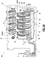
- FIGS. 1 , 2 , 3 , and 4 are schematic illustrations of an example biological sample input section of a cartridge 100 for evaluating hemostasis.
- FIG. 1 shows a perspective view of an example biological sample input of a cartridge for use in disposable system, in accordance with an illustrative embodiment.
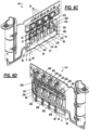
- FIG. 2 shows a side view of the example biological sample input of FIG. 1 with a casing, in accordance with an illustrative embodiment.
- FIG. 3 shows a side cross-sectional view of the example biological sample input of FIG. 2 with a sample holding tube attached thereon, in accordance with an illustrative embodiment.
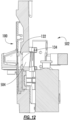
- FIG. 4 shows a detailed view of the example biological sample input of FIG. 3 , in accordance with an illustrative embodiment.
- the input section of the cartridge comprises a well to which fluid sample can be placed, for example, by way of a pipette or tube.
- the cartridge 100 has a dual connection tab 28a, 28b for coupling the cartridge 100 to a sample container guide 1 (shown in FIG. 2 ).
- the sample container guide 1 when mated with the cartridge 100, aligns a sample container 2 to a sample input port 3 of the cartridge 100.
- the cartridge 100 also includes an alignment tab 29 that is configured to slide into an alignment groove 30 of the sample container guide 1 to further stabilize the coupling of the sample container guide 1 to the cartridge 100.
- the sample container guide 1 can further provide a hard stop 5 (shown in FIG. 3 ) to hold the sample container 2 at the appropriate height to establish fluidic communication with the cartridge 100.
- the sample container 2 is an evacuated tube (also referred to herein as the sample holding tube 2 ) such as a BD Vacutainer TM tube, and the sample input port 3 comprises one or more needles required for sample transferring 3a and venting 4 (see FIG. 1 ). Though shown as concentric in the figures, the needles can be configured to be concentric, side by side, or integrated.
- the sample transferring needle 3a includes inlets ( 3b and 3d ) and an outlet 3c that terminates in a sample inlet chamber 26 of the cartridge 100.
- the sample inlet chamber 26 is in fluid communication with an inlet pathway 8 that leads to a retention/heating chamber 6 (see FIG. 5A ).
- the venting needle 4 includes an outlet 4a that is configured to terminate within the sample container 2 when attached and is spaced apart from the inlet 3d so as to minimize bubbles being drawn into the inlets 3b and 3d.
- the venting needle 4 also has an inlet 4b that terminates in a venting inlet chamber 27 of the cartridge.
- the venting inlet chamber 27 is in fluid communication with a vent pathway 9 that, in some embodiments, terminates at a filter chamber 9a (shown in FIG. 5A ) housing a filter.
- An alternative sample container 2 can be utilized, such as a syringe, which requires a luer lock connection on the cartridge 100.
- the input section of the cartridge comprises a well to which fluid sample can be placed, for example, by way of a pipette or tube.
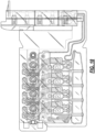
- FIGS. 5A , 5B , 7 , and 8 are schematic illustrations of biological fluid pathways of the example cartridge 100 in accordance to an embodiment.
- FIGS. 5A and 5B each shows the biological fluid pathways of four testing circuits (corresponding to test chambers 16a, 16b, 16c, and 16d, shown in FIG. 5A ), also referred to herein as Hemostasis testing circuits, that are located on a sample preparation plane, in accordance with an illustrative embodiment. Though shown with four testing circuits, additional circuits or less may be included, including, e.g., two, three, five, six, seven, eight, and etc.
- FIG. 5B further shows of the cartridge body of FIG.
- FIG. 5A shows the back-side of the cartridge of FIG. 5A and includes an interconnection plane that interfaces to the sample preparation plane, that collectively form the biological fluid pathways for the testing circuits, in accordance with an illustrative embodiment.
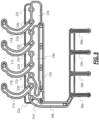
- FIG. 8 shows portions of the biological fluid pathways that are on the interconnection plane of FIG. 7 , in accordance with an illustrative embodiment.
- FIGS. 5A and 5B A first plane of fluid pathways of the cartridge 100 is shown in FIGS. 5A and 5B .
- the first plane of fluid pathways of the cartridge 100 may alternatively be referred to as a front plane of the cartridge 100.
- FIGS. 7 and 8 each shows a second plane of fluid pathways of the cartridge 100 in which FIG. 8 shows the fluid pathways in the second plane isolated from the remainder of the structure of the cartridge 100 for ease of understanding.
- the second plane of fluid pathways of the cartridge 100 may alternatively be referred to as a back plane of the cartridge 100.
- the fluid pathways between the first and second planes are connected by fluidic vias that traverse across the various planes of the cartridge 100.
- the venting inlet chamber 27 is in fluid communication with a vent pathway 9.
- the vent pathway 9 may terminate at a filter chamber 9a (shown in FIG. 5A ), which may house a filter therein.
- the filter chamber 9a in the first plane of fluid pathways of the cartridge 100 is in fluid communication with a vent port 22i (shown in FIG. 8 ) in the second plane of fluid pathways of the cartridge 100.
- cartridge 100 couples with the measurement system (also referred to herein as the instrument) via the vent port 22i to provide atmospheric pressure to vent pathway 9.
- the sample transferring needle outlet 3c terminates in a sample inlet chamber 26 of the cartridge 100.
- the sample inlet chamber 26 is in fluid communication with an inlet pathway 8.
- the sample inlet pathway 8 provides a fluid communication pathway between the sample inlet chamber 26 and a retaining/heating chamber 6 (also referred to herein as heating chamber 6 or as a "first chamber”) (shown in FIG. 5A ).
- the label "first”, “second”, and “third” as used herein is provided merely as labels and do not intended to connote a sequence.
- the heating chamber 6 is configured to mate with a corresponding thermal regulating (e.g., heating/cooling) system in the measurement system to warm or cool the sample toward or to, or near, a pre-defined temperature.
- the heating chamber 6, as provided herein, facilitate uniform conditioning of the test fluid prior to the fluid be metered or aliquoted to their respective testing, thus reducing variability in the test sample that can affect subsequent measurements and analysis.
- the shape of the heating chamber 6 can be optimized for heating/cooling transfer, as in the case here in which a thin cross-section with thin walls is used.
- the materials of the cartridge 100 can also be optimized to facilitate heating/cooling.
- the sample heating/cooling conditioning stage can also be implemented in one or more chamber/channels of the cartridge design and it is not limited to just occur within just the heating chamber 6.
- a stirring, rotating, or oscillating element (not shown) can be placed in the heating chamber 6 that may be controlled by the measurement system to promote uniform temperature heating or cooling.
- test fluid in the heating chamber 6 may be vibrated by the measurement system vibrating the cartridge 100 to promote uniform temperature conditioning of the test fluid.
- temperature measurement is conducted of the test sample in the cartridge 100.
- a sensor can be incorporated in the measurement system or in the cartridge 100.
- a thermistor or thermocouple can be placed in physical contact with the cartridge 100, or biological sample (such as blood).
- an IR thermometer is pointed at the cartridge 100 or biological sample.
- the cartridge 100 may incorporate a small well through which the incoming blood passes, rather than having direct contact with the blood.
- the temperature of the test sample may be assessed at or near the heating chamber 6. In other embodiments, the temperature of the test sample may be assessed while the test sample is flowing through channels as it is directed toward the test chambers 16.
- the sample inlet pathway 8 terminates at a first corner 6a of the heating chamber 6, shown as the top left corner of heating chamber 6 in FIGS. 5A and 5B .
- chambers along the fluid pathways are generally filled from the top as to prevent blood to backflow into the inlet.
- a fill outlet channel 10a extends from a second corner 6b of the heating chamber 6 opposite from the first corner 6a.
- the fill outlet channel 10a extends to a filter chamber 10 with a filter therein.
- the filter chamber 10 e.g., as shown in FIGS. 5A and 5B
- the filter chamber 10 in the first plane of fluid pathways of the cartridge 100 is in fluid communication with a heating-chamber fill channel 10b shown in the second plane of fluid pathways of the cartridge 100 (see FIG. 8 ).
- the fill conduit 10b is in fluid communication with a pressure port 22a (see also Fig. 8 ) that facilitate filling of the heating chamber 6.
- the conduit 10b is a part of a network of conduits used to consolidate pressure ports (e.g., 22a as discussed, as well as 22b-22i to be later discussed) of the cartridge 100 to one or more areas to which the measurement system can coupled with its pressure control interfaces.
- FIGS. 6A and 6B show a front perspective view and a back perspective view of FIGS. 5A , 5B , and 8 with additional labels corresponding to the description of this section.
- the instrument's fluid pump aspirates the sample through the input port 3 (see FIGS. 1-2 ) via the connection ports 22 (see FIG. 7 ) (also referred to herein as pressure ports) and into the heating chamber 6 (see FIG. 5A or 5B ) of the cartridge 100.
- the instrument's fluid pump may be in communication with and apply differential pressure (e.g., positive or negative) to a pressure port 22a (see FIG. 8 ). This in turn creates an applied pressure along the fill conduit 10b, within the heating chamber 6, and along the inlet pathway 8 to aspirate the sample into the heating chamber 6.
- the inner vent needle 4 is linked to the isolated pathway 9 that receives atmospheric pressure from the instrument via the vent port 22i (see FIG.
- the filter within filter chamber 10 is clogged and creates a pressure spike that is detected by the instrument, causing the instrument to turn off the fluidic pump.
- the instrument may also close the vent port 22i or otherwise discontinue supplying atmospheric pressure via vent port 22i upon detecting the pressure spike.
- Alternative filling detection techniques could also be used, i.e., optical sensors placed at the desired fill level, volumetric control, fixed time of pressure alteration (negative and/or positive pressures), ultrasound detectors placed at the desired fill level, etc.
- the sample remains in the heating chamber until the desired temperature is reached, which can for example be at or near body temperature of a normal and typical subject (e.g., about 37°C for a healthy person). In other instances, other desired temperatures may be warranted.
- the shape of the heating chamber 6 and the channels leading to the sample metering chambers 11 are configured so that bubbles that might be present in the fluid sample are trapped away from the rest of the fluidic circuit.
- the shape of the inlet pathway 8 includes an anti-siphon feature 8a (see FIG. 5A and 5B ) and is configured to reduce the occurrence of bubbles forming in the heating chamber 6 and prevent siphoning to and from the sample container 2.
- FIGS. 6A and 6B also show labels corresponding to the description of this section.
- an example user interface is described in commonly assigned U.S. Pub. No. 2011/0252352 to Viola et al. , which is incorporated by reference herein in its entirety.
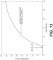
- the example user interface may be used to display the measured hemostatic indexes as discussed in relation to Table 4, among other parameters. Table 4. Parameters reported from measurement of the preferred embodiments discussed in relation to Table 2.
- the testing chambers 16 are shaped to facilitate ultrasound testing of viscoelastic properties of the sample, but alternative geometries can also be implemented to facilitate other types of testing.
- Such an ultrasound testing system is described in commonly assigned U.S. Patent No. 9,726,647 and U.S. Pub. No. 2016/0139159 , both of which are hereby incorporated by reference in their entirety.
- Ultrasound transducers in the measuring system connect with the testing chambers 16 of the cartridge 100 via compliant and deformable elastomers 21 which are affixed to a testing block 21d on the cartridge 100.
- Example elastomeric materials optionally include, Dynaflex D3202, Versaflex OM 9-802CL, Maxelast 54740, RTP 6035, Versaflex CL2003X, among others.
- the testing block 21d is aligned with the testing chambers 16 (see FIG. 5B ) via alignment slots 23 and 24 on the cartridge 100.
- the elastomers 21 may be affixed to the testing block 21d via a flange 21a on the elastomers 21.
- the flange 21a may have a plurality of alignment holes 21b that may receive corresponding alignment pegs (not shown) from the testing block 21d.
- the soft elastomers 21 may also each include a lens 21c that focuses ultrasound energy within the sample at the testing chambers 16.
- a lens assembly 131 includes a rigid substrate 132 and a couplant 134 that can be positioned at the back end of each test chamber.
- each couplant 134 comprises an elastomeric material.
- the elastomeric material is a thermoplastic elastomer (TPE).
- TPE thermoplastic elastomer
- Example elastomeric materials optionally include, Dynaflex D3202, Versaflex OM 9-802CL, Maxelast 54740, RTP 6035, Versaflex CL2003X, among others.
- the couplant is over-molded to the rigid substrate.
- the couplant is mechanically anchored to the rigid substrate.
- each couplant 134 and the open space of each test chamber is a rigid substrate 132.
- the rigid substrate and the couplant form an interface that focuses ultrasound transmitted (e.g. lens assembly) by an ultrasonic transducer into the chamber's open space and onto any biological fluid and/or reagents in the chamber.
- the rigid substrate of the lens can comprise a material which allows sound to pass and that can act to focus ultrasound at some level within the space.
- the rigid substrate comprises a styrene.
- the lens assembly may be glued or welded to the surface 101 of the testing block 21d (shown in FIG. 11 as element 132) to secure the lens in place in an orientation that allows the desired focusing of sound.
- the lens assembly is optionally manufactured together with the surface 101 of the testing block 21d.
- the rigid substrate 132 can be molded with the surface 101 of the testing block 21d and the couplant 134 can be overmolded or mechanically anchored on the rigid substrate.
- materials can be used to construct the device. For example, plastics can be used for single use, disposable cartridges.
- each of the test chambers 116 can have a lens assembly positioned over the large opening of each chamber's open space. In this way, each chamber can be separately interrogated by focused ultrasound.
- the couplant 134 when placed in the instrument, can be placed in acoustic communication with a transducer for supplying ultrasound through the lens assembly and into a test chamber 116.
- an intermediate layer of an acoustically permeable material is positioned between an ultrasonic transducer and the couplant.
- intermediate layer or block of Rexolite ® or TPX ® can be used. The intermediate layer can be forced against the couplant and can be in acoustic contact with the transducer.
- sound generated by a transducer passes through the intermediate layer, through the couplant, through the rigid substrate, and is focused within the biological sample, such as blood, and reagent in the test chamber.
- Some of the sound directed into chamber contacts the distal interior surface 111 of the test chamber, which is defined by the surface 126.
- the surface is polystyrene.
- the distal interior surface has a known geometry and is positioned at a known distance from the ultrasound source.
- the distal interior surface 111 is used as a calibrated reflector, which is used to estimate the speed of sound and attenuation of sound in a test chamber at base line and during the process of clot formation and clot dissolution.
- the sound generated by the transducer can be focused within the biological sample in a test chamber using a parabolic mirror that is coupled to the biological sample using an elastomer.
- cartridge and features described herein can be modified for use with other types of measurement systems such as thromboelastography-based systems, thromboelastometry-based systems, optical-based systems, fluorescence-based systems, colorimetric-based systems, aggregometry-based systems, resonance-based system, and an electrical impedance-based system, among others.
- measurement systems such as thromboelastography-based systems, thromboelastometry-based systems, optical-based systems, fluorescence-based systems, colorimetric-based systems, aggregometry-based systems, resonance-based system, and an electrical impedance-based system, among others.
- An apparatus comprising:
- Clause 2 The apparatus of clause 1, wherein at least one of the one or more fluidic circuits comprise one or more pockets configured to house at least one lyophilized bead comprising the reagent, or the combination of regents.
- Clause 3 The apparatus of any one of clauses 1 or 2, wherein at least one of the one or more fluidic circuits comprises one or more liquid-retaining pockets to house the reagent, or the combination of regents.
- Clause 4 The apparatus of any one of the clauses 1-3, wherein the input port is communicatively coupled to a first pressure port, wherein pressure when applied to the first pressure port causes the evacuation of the contents of the sample holding tube through the input port to the first chamber.
- Clause 5 The apparatus of any one of clauses 1-4, wherein the input port forms a part of a needle assembly structurally configured to establish fluidic communication and evacuate contents of the sample holding tube.
- Clause 7 The apparatus of any one of clauses 1-6, wherein the input port is structurally configured to couple to a luer lock configured to connect to the sample holding tube.
- Clause 8 The apparatus of any one of clauses 1-7, wherein the first chamber is configured to mate with a corresponding thermal regulating surface of a sub-system component of the measurement system to condition the received sample to, or near, the desired temperature.
- Clause 11 The apparatus of clause 10, wherein the first chamber and/or the channel portion of the one or more fluidic circuits is in physical proximity with a sensor of the measurement system configured to measure a temperature of the sample received in the first chamber.
- Clause 12 The apparatus of any one of clauses 1-11, comprising a filter positioned within the first pressure port, wherein the filter is configured to allow air to move through the first pressure port but prevent fluid from moving there through.
- each of the one or more fluidic circuits comprises a third set of fluid pathways in fluidic communication between a respective second chamber and test chamber, wherein a portion of third set of fluid pathways are arranged as a serpentine-shaped conduit.
- each of the second chambers is connected to a second pressure port, wherein pressure when applied to the second pressure port causes the filling of the second chamber.
- each of the second chambers is connected to a vent port, wherein the vent port is configured to be closed while the sample is metered into the aliquot in the second chamber and further configured to be open to atmospheric pressure after the sample is metered into the aliquot in the second chamber.
- Clause 16 The apparatus of any one of clauses 1-15, wherein the serpentine-shaped conduit forms a serpentine reservoir between the testing chamber and the second chamber, and wherein a metered sample is directed through portions of the serpentine-shaped conduit to facilitate mixing of the metered sample and the reagent, or the combination of reagents.
- Clause 17 The apparatus of clause 16, wherein the metered sample is alternatively and multiplicatively directed, for each of the one or more fluidic circuits, between a first position in a fluidic circuit a second position in the fluidic circuit, wherein the length first position and second portion includes at least a portion of the serpentine conduit.
- each of the test chambers is connected to a third pressure port, wherein when pressure is applied to the third pressure port causes the test sample to flow toward the test chamber through a respective serpentine conduit.
- Clause 20 The apparatus of clause 19, wherein the serpentine reservoir includes an optical detection zone.
- each of the one or more fluidic circuits further comprises a mixing zone between the testing chamber and the second chamber, the mixing zone comprising one or more ferromagnetic beads or bars therein.
- Clause 22 The apparatus of any one of clauses 1-21, wherein at least one of the one or more fluidic circuits comprises one or more quality testing portals, wherein the one or more quality testing portals is configured to be sensed optically or electrically.
- Clause 23 The apparatus of clause 22, wherein at least one of the one or more quality testing ports is configured to be sampled for characteristics of the metered sample.
- Clause 24 The apparatus of any one of clauses 1-23, wherein the testing chamber comprises a lens configured to direct ultrasonic pulses generated by the measurement system into the testing chamber.
- Clause 25 The apparatus of any one of clauses 1-24, further comprising: for each of the one or more fluidic pathways, the second chamber in fluidic communication with the first chamber, the one or more reagent pockets, and the testing chamber.
- Clause 26 The apparatus of any one of clauses 1-25, wherein at least one of the reagents, or combination of reagents, located in the one or more fluidic circuits is selected from the group consisting of an intrinsic pathway activator, an extrinsic pathway activator, and a coagulation activator.
- Clause 27 The apparatus of any one of clauses 1-26, wherein at least one of the reagents, or combination of reagents, located in the one or more fluidic circuits is selected from the group consisting of a platelet activator, a platelet inhibitor, and a fibrinolytic function inhibitor.
- Clause 28 The apparatus of any one of clauses 1-27, wherein at least one of the reagents, or combination of reagents, located in the one or more fluidic circuits is selected from the group consisting of a FXIIIa inhibitor, thrombomodulin, polybrene, heparin, corn trypsin inhibitor, adenosine, GPRP (Gly-Pro-Arg-Pro), calcium, fibronectin, collagen, an immuno-detection reagent, and heparinase I, or a combination thereof.
- a FXIIIa inhibitor thrombomodulin
- polybrene polybrene
- heparin corn trypsin inhibitor
- adenosine GPRP (Gly-Pro-Arg-Pro)
- calcium calcium
- fibronectin collagen
- an immuno-detection reagent an immuno-detection reagent
- heparinase I or a combination thereof.
- Clause 29 The apparatus of any one clauses 1-28, wherein the measurement system is selected from the group consisting of a sonorheometry-based system, thromboelastography-based system, a thromboelastometry-based system, an optical-based system, a fluorescence-based system, a colorimetric-based system, an aggregometry-based system, a resonance-based system, and an electrical impedance-based system.
- the measurement system is selected from the group consisting of a sonorheometry-based system, thromboelastography-based system, a thromboelastometry-based system, an optical-based system, a fluorescence-based system, a colorimetric-based system, an aggregometry-based system, a resonance-based system, and an electrical impedance-based system.
- Clause 30 The apparatus of any one of clauses 1-29, comprising: at least four test channels, wherein a first test channel comprise an intrinsic pathway activator, wherein a second test channel comprises the intrinsic pathway activator and a heparin neutralizer, wherein a third test channel comprises an extrinsic pathway activator, and wherein a fourth test channel comprises the extrinsic pathway activator and a platelet inhibitor.
- Clause 31 The apparatus of any one of clauses 1-29, comprising: at least four test channels, wherein a first test channel comprise an intrinsic pathway activator, wherein a second test channel comprises an extrinsic pathway activator and a fibrinolytic function inhibitor, wherein a third test channel comprises an extrinsic pathway activator, and wherein a fourth test channel comprises the extrinsic pathway activator and a platelet inhibitor.
- Clause 32 The apparatus of clause 30 or 31, wherein the third channel and the fourth channel each includes Hexadimethrine bromide (polybrene).
- Clause 33 The apparatus of clause 31 wherein the fourth test channel further includes a fibrinolytic function inhibitor.
Landscapes
- Health & Medical Sciences (AREA)
- Life Sciences & Earth Sciences (AREA)
- Engineering & Computer Science (AREA)
- Chemical & Material Sciences (AREA)
- Biomedical Technology (AREA)
- Physics & Mathematics (AREA)
- Hematology (AREA)
- Immunology (AREA)
- General Health & Medical Sciences (AREA)
- Analytical Chemistry (AREA)
- General Physics & Mathematics (AREA)
- Biochemistry (AREA)
- Pathology (AREA)
- Urology & Nephrology (AREA)
- Molecular Biology (AREA)
- Medicinal Chemistry (AREA)
- Food Science & Technology (AREA)
- Biophysics (AREA)
- Ecology (AREA)
- Acoustics & Sound (AREA)
- Clinical Laboratory Science (AREA)
- Microbiology (AREA)
- Chemical Kinetics & Catalysis (AREA)
- Biotechnology (AREA)
- Cell Biology (AREA)
- Investigating Or Analysing Biological Materials (AREA)
- Automatic Analysis And Handling Materials Therefor (AREA)
Applications Claiming Priority (3)
| Application Number | Priority Date | Filing Date | Title |
|---|---|---|---|
| US201762488045P | 2017-04-20 | 2017-04-20 | |
| EP18724652.5A EP3612838B1 (de) | 2017-04-20 | 2018-04-20 | Einwegsystem zur analyse der hämostatischen funktion |
| PCT/US2018/028630 WO2018195468A2 (en) | 2017-04-20 | 2018-04-20 | Disposable system for analysis of hemostatic function |
Related Parent Applications (1)
| Application Number | Title | Priority Date | Filing Date |
|---|---|---|---|
| EP18724652.5A Division EP3612838B1 (de) | 2017-04-20 | 2018-04-20 | Einwegsystem zur analyse der hämostatischen funktion |
Publications (2)
| Publication Number | Publication Date |
|---|---|
| EP4481381A2 true EP4481381A2 (de) | 2024-12-25 |
| EP4481381A3 EP4481381A3 (de) | 2025-02-26 |
Family
ID=62165630
Family Applications (2)
| Application Number | Title | Priority Date | Filing Date |
|---|---|---|---|
| EP18724652.5A Active EP3612838B1 (de) | 2017-04-20 | 2018-04-20 | Einwegsystem zur analyse der hämostatischen funktion |
| EP24197053.2A Pending EP4481381A3 (de) | 2017-04-20 | 2018-04-20 | Einwegsystem zur analyse der hämostatischen funktion |
Family Applications Before (1)
| Application Number | Title | Priority Date | Filing Date |
|---|---|---|---|
| EP18724652.5A Active EP3612838B1 (de) | 2017-04-20 | 2018-04-20 | Einwegsystem zur analyse der hämostatischen funktion |
Country Status (11)
| Country | Link |
|---|---|
| US (3) | US11366093B2 (de) |
| EP (2) | EP3612838B1 (de) |
| JP (3) | JP7432500B2 (de) |
| CN (3) | CN110691972B (de) |
| AU (2) | AU2018254584B2 (de) |
| CA (1) | CA3065331A1 (de) |
| DK (1) | DK3612838T3 (de) |
| ES (1) | ES2991730T3 (de) |
| FI (1) | FI3612838T3 (de) |
| PT (1) | PT3612838T (de) |
| WO (1) | WO2018195468A2 (de) |
Families Citing this family (15)
| Publication number | Priority date | Publication date | Assignee | Title |
|---|---|---|---|---|
| US8448499B2 (en) | 2008-12-23 | 2013-05-28 | C A Casyso Ag | Cartridge device for a measuring system for measuring viscoelastic characteristics of a sample liquid, a corresponding measuring system, and a corresponding method |
| US10175225B2 (en) | 2014-09-29 | 2019-01-08 | C A Casyso Ag | Blood testing system and method |
| US10816559B2 (en) | 2014-09-29 | 2020-10-27 | Ca Casyso Ag | Blood testing system and method |
| US10539579B2 (en) | 2014-09-29 | 2020-01-21 | C A Casyso Gmbh | Blood testing system and method |
| US9726647B2 (en) | 2015-03-17 | 2017-08-08 | Hemosonics, Llc | Determining mechanical properties via ultrasound-induced resonance |
| EP4603188A3 (de) * | 2019-03-15 | 2025-10-29 | Coagulation Sciences, LLC | Koagulationsprüfvorrichtung, system und verfahren zur verwendung |
| US10429377B1 (en) | 2019-03-15 | 2019-10-01 | Coagulation Sciences Llc | Coagulation test device, system, and method of use |
| US11331674B2 (en) * | 2019-04-29 | 2022-05-17 | Hach Company | Liquid mixing |
| JP7681270B2 (ja) * | 2020-07-21 | 2025-05-22 | ソニーグループ株式会社 | 血液凝固系解析装置、血液凝固系測定装置、血液凝固系測定システム、血液凝固系解析方法及び血液凝固系測定方法 |
| JPWO2022145477A1 (de) * | 2020-12-28 | 2022-07-07 | ||
| CN114324753A (zh) * | 2021-12-21 | 2022-04-12 | 广州万孚生物技术股份有限公司 | 试剂卡 |
| US20230243856A1 (en) | 2022-01-31 | 2023-08-03 | Instrumentation Laboratory Company | Identifying direct oral factor xa inhibitors |
| US20240218344A1 (en) | 2022-12-23 | 2024-07-04 | Instrumentation Laboratory Company | Liquid thrombin reagent |
| EP4658806A1 (de) * | 2023-02-01 | 2025-12-10 | Haemonetics Corporation | Einwegkartusche zur klassifizierung von antikoagulans und verfahren zur verwendung |
| US20250362314A1 (en) | 2024-05-24 | 2025-11-27 | Instrumentation Laboratory Co. | Compositions for detection of hyperfibrinolysis and fibrinolytic shutdown and uses thereof |
Citations (6)
| Publication number | Priority date | Publication date | Assignee | Title |
|---|---|---|---|---|
| US7892188B2 (en) | 2003-10-22 | 2011-02-22 | Hemosonics, Llc | Method and apparatus for characterization of clot formation |
| WO2011127436A2 (en) | 2010-04-08 | 2011-10-13 | Hemosonics, Llc | Hemostatic parameter display |
| US20120294767A1 (en) | 2011-05-19 | 2012-11-22 | Hemosonics Llc | Portable hemostasis analyzer |
| US9031701B2 (en) | 2011-02-15 | 2015-05-12 | Hemosonics Llc | Characterization of blood hemostasis and oxygen transport parameters |
| US9272280B2 (en) | 2011-02-15 | 2016-03-01 | Hemosonics Llc | Device, systems and methods for evaluation of hemostasis |
| US20160274067A1 (en) | 2015-03-17 | 2016-09-22 | Hemosonics, Llc | Determining Mechanical Properties via Ultrasound-Induced Resonance |
Family Cites Families (144)
| Publication number | Priority date | Publication date | Assignee | Title |
|---|---|---|---|---|
| CH610111A5 (de) | 1977-01-13 | 1979-03-30 | Contraves Ag | |
| US4900679A (en) | 1983-01-26 | 1990-02-13 | University Of Medicine And Dentistry Of New Jersey | Method for determining the existence and/or the monitoring of a pathological condition in a mammal and a test kit therefor |
| US4814247A (en) | 1983-01-26 | 1989-03-21 | University Of Medicine And Dentistry Of New Jersey | Method for determining the existance and/or the monitoring of a pathological condition in a mammal |
| US4705756A (en) | 1983-01-26 | 1987-11-10 | University Of Medicine And Dentistry Of New Jersey | Method of determining the existence and/or the monitoring of a pathological condition in a mammal |
| US4558589A (en) | 1984-10-09 | 1985-12-17 | Miles Laboratories, Inc. | Ultrasonic coagulation monitor and method |
| US4695956A (en) | 1984-11-01 | 1987-09-22 | Leveen Eric G | Apparatus and method of quantifying hemostasis using oscillations from a transducer immersed in the blood sample |
| US4756884A (en) | 1985-08-05 | 1988-07-12 | Biotrack, Inc. | Capillary flow device |
| US5204525A (en) | 1985-08-05 | 1993-04-20 | Biotrack | Capillary flow device |
| US4849340A (en) | 1987-04-03 | 1989-07-18 | Cardiovascular Diagnostics, Inc. | Reaction system element and method for performing prothrombin time assay |
| SE8704255L (sv) | 1987-11-02 | 1989-05-03 | Hans W Persson | Akustisk metod foer maetning av egenskaper hos ett roerligt medium |
| US4944409A (en) | 1988-02-10 | 1990-07-31 | Curwood, Inc. | Easy open package |
| US4852577A (en) | 1988-04-07 | 1989-08-01 | The United States Of America As Represented By The Department Of Health And Human Services | High speed adaptive ultrasonic phased array imaging system |
| US5104975A (en) | 1988-07-08 | 1992-04-14 | Cetus Corporation | Compositions for detecting ras gene proteins and cancer therapeutics |
| US5234839A (en) | 1988-07-08 | 1993-08-10 | Cetus Oncology Corporation | Compositions for detecting ras gene proteins and cancer therapeutics |
| US5091304A (en) | 1989-08-21 | 1992-02-25 | International Technidyne Corporation | Whole blood activated partial thromboplastin time test and associated apparatus |
| US5016469A (en) | 1989-09-29 | 1991-05-21 | Sienco, Inc. | Fluid viscoelastic test apparatus and method |
| US5273517A (en) | 1991-07-09 | 1993-12-28 | Haemonetics Corporation | Blood processing method and apparatus with disposable cassette |
| US6114135A (en) | 1991-11-08 | 2000-09-05 | Goldstein; Sheldon | Multiple coagulation test system and method of using a multiple coagulation test system |
| US5205159A (en) | 1992-01-17 | 1993-04-27 | Virginia Commonwealth University | Apparatus and method for measuring clot elastic modulus and force development on the same blood sample |
| US5993389A (en) | 1995-05-22 | 1999-11-30 | Ths International, Inc. | Devices for providing acoustic hemostasis |
| US5744898A (en) | 1992-05-14 | 1998-04-28 | Duke University | Ultrasound transducer array with transmitter/receiver integrated circuitry |
| US5331964A (en) | 1993-05-14 | 1994-07-26 | Duke University | Ultrasonic phased array imaging system with high speed adaptive processing using selected elements |
| US5447440A (en) * | 1993-10-28 | 1995-09-05 | I-Stat Corporation | Apparatus for assaying viscosity changes in fluid samples and method of conducting same |
| US5473536A (en) | 1994-04-04 | 1995-12-05 | Spacelabs Medical, Inc. | Method and system for customizing the display of patient physiological parameters on a medical monitor |
| WO1995029737A1 (en) | 1994-05-03 | 1995-11-09 | Board Of Regents, The University Of Texas System | Apparatus and method for noninvasive doppler ultrasound-guided real-time control of tissue damage in thermal therapy |
| US5487387A (en) | 1994-06-03 | 1996-01-30 | Duke University | Method and apparatus for distinguishing between solid masses and fluid-filled cysts |
| US5888826A (en) | 1994-06-30 | 1999-03-30 | Dade Behring Inc. | Combination reagent holding and test device |
| JP3905124B2 (ja) | 1994-10-19 | 2007-04-18 | ペンタファルム アクチェンゲゼルシャフト | 試液の凝結特性測定装置 |
| US5504011A (en) | 1994-10-21 | 1996-04-02 | International Technidyne Corporation | Portable test apparatus and associated method of performing a blood coagulation test |
| AUPM934994A0 (en) | 1994-11-09 | 1994-12-01 | Commonwealth Scientific And Industrial Research Organisation | Particle property measurement |
| US5655535A (en) | 1996-03-29 | 1997-08-12 | Siemens Medical Systems, Inc. | 3-Dimensional compound ultrasound field of view |
| US5899861A (en) | 1995-03-31 | 1999-05-04 | Siemens Medical Systems, Inc. | 3-dimensional volume by aggregating ultrasound fields of view |
| US5605154A (en) | 1995-06-06 | 1997-02-25 | Duke University | Two-dimensional phase correction using a deformable ultrasonic transducer array |
| US5629209A (en) | 1995-10-19 | 1997-05-13 | Braun, Sr.; Walter J. | Method and apparatus for detecting viscosity changes in fluids |
| US5810731A (en) | 1995-11-13 | 1998-09-22 | Artann Laboratories | Method and apparatus for elasticity imaging using remotely induced shear wave |
| US5606971A (en) | 1995-11-13 | 1997-03-04 | Artann Corporation, A Nj Corp. | Method and device for shear wave elasticity imaging |
| US5854423A (en) | 1996-03-20 | 1998-12-29 | Venegas; Jose G. | Apparatus and method for assessment of visco-elasticity and shear adherence strength properties of blood clots |
| US6221672B1 (en) | 1996-04-30 | 2001-04-24 | Medtronic, Inc. | Method for determining platelet inhibitor response |
| US5673699A (en) | 1996-05-31 | 1997-10-07 | Duke University | Method and apparatus for abberation correction in the presence of a distributed aberrator |
| EP0839497A1 (de) | 1996-11-01 | 1998-05-06 | EndoSonics Corporation | Verfahren zum Messen des Volumenflusses und des Geschwindigkeitsprofils in einen Lumen oder einer Körperhöhle |
| US5921928A (en) | 1996-12-05 | 1999-07-13 | Mayo Foundation For Medical Education And Research | Acoustic force generation by amplitude modulating a sonic beam |
| US5951951A (en) | 1997-04-30 | 1999-09-14 | Medtronic, Inc. | Platelet function evaluation technique for citrated whole blood |
| EP1006881A4 (de) | 1997-06-02 | 2004-04-28 | Univ Duke | Vorrichtung und verfahren zur kinetisch-akkustischen augenuntersuchung |
| US6046051A (en) | 1997-06-27 | 2000-04-04 | Hemosense, Inc. | Method and device for measuring blood coagulation or lysis by viscosity changes |
| US6016712A (en) | 1997-09-18 | 2000-01-25 | Accumetrics | Device for receiving and processing a sample |
| GB9800813D0 (en) | 1998-01-16 | 1998-03-11 | Andaris Ltd | Improved ultrasound contrast imaging method and apparatus |
| JPH11316180A (ja) | 1998-01-23 | 1999-11-16 | Koninkl Philips Electronics Nv | 血管中の粘度及び圧勾配を決定するエコ―検査方法及び装置 |
| US6270459B1 (en) | 1998-05-26 | 2001-08-07 | The Board Of Regents Of The University Of Texas System | Method for estimating and imaging of transverse displacements, transverse strains and strain ratios |
| AU4957699A (en) | 1998-06-24 | 2000-01-10 | Chen & Chen, Llc | Fluid sample testing system |
| US6283917B1 (en) | 1998-10-01 | 2001-09-04 | Atl Ultrasound | Ultrasonic diagnostic imaging system with blurring corrected spatial compounding |
| US6117081A (en) | 1998-10-01 | 2000-09-12 | Atl Ultrasound, Inc. | Method for correcting blurring of spatially compounded ultrasonic diagnostic images |
| US6277074B1 (en) | 1998-10-02 | 2001-08-21 | University Of Kansas Medical Center | Method and apparatus for motion estimation within biological tissue |
| DE102004033595A1 (de) | 2004-07-07 | 2006-02-16 | Celon Ag Medical Instruments | Bipolare Koagulationselektrode |
| US6797519B2 (en) | 2001-10-10 | 2004-09-28 | Haemoscope Corporation | Method and apparatus for diagnosing hemostasis |
| US7179652B2 (en) | 1999-02-22 | 2007-02-20 | Haemoscope Corporation | Protocol for monitoring platelet inhibition |
| US8008086B2 (en) | 1999-02-22 | 2011-08-30 | Cora Healthcare, Inc. | Protocol for monitoring direct thrombin inhibition |
| US6225126B1 (en) | 1999-02-22 | 2001-05-01 | Haemoscope Corporation | Method and apparatus for measuring hemostasis |
| US7732213B2 (en) | 1999-02-22 | 2010-06-08 | Coramed Healthcare, Inc. | Method of evaluating patient hemostasis |
| US6787363B2 (en) | 1999-02-22 | 2004-09-07 | Haemoscope Corporation | Method and apparatus for hemostasis and blood management |
| US6613573B1 (en) | 1999-02-22 | 2003-09-02 | Haemoscope Corporation | Method and apparatus for monitoring anti-platelet agents |
| US6451610B1 (en) | 1999-04-14 | 2002-09-17 | International Technidyne Corporation | Method and apparatus for coagulation based assays |
| US6692439B1 (en) | 1999-07-07 | 2004-02-17 | University Of Virginia Patent Foundation | Angular scatter imaging system using translating apertures and method thereof |
| US7192726B1 (en) | 1999-08-13 | 2007-03-20 | Hemodyne, Inc. | Method of using platelet contractile force and whole blood clot elastic modulus as clinical markers |
| US6264609B1 (en) | 1999-09-15 | 2001-07-24 | Wake Forest University | Ultrasound apparatus and method for tissue characterization |
| US6750053B1 (en) | 1999-11-15 | 2004-06-15 | I-Stat Corporation | Apparatus and method for assaying coagulation in fluid samples |
| US6412344B1 (en) | 1999-11-15 | 2002-07-02 | Rosemount Aerospace Inc. | Fluid level sensor with dry couplant |
| US6535835B1 (en) | 2000-01-31 | 2003-03-18 | Ge Medical Systems Global Technology Company, Llc | Angle independent ultrasound volume flow measurement |
| WO2001071366A2 (en) | 2000-03-17 | 2001-09-27 | The Board Of Regents Of The University Of Texas System | Power spectral strain estimators in elastography |
| US7374538B2 (en) | 2000-04-05 | 2008-05-20 | Duke University | Methods, systems, and computer program products for ultrasound measurements using receive mode parallel processing |
| US6371912B1 (en) | 2000-04-05 | 2002-04-16 | Duke University | Method and apparatus for the identification and characterization of regions of altered stiffness |
| US6402704B1 (en) | 2000-04-18 | 2002-06-11 | Sonexxus Incorporated | Prothrombin test apparatus for home use |
| US6436722B1 (en) | 2000-04-18 | 2002-08-20 | Idexx Laboratories, Inc. | Device and method for integrated diagnostics with multiple independent flow paths |
| US6541262B1 (en) | 2000-04-28 | 2003-04-01 | Medtronic, Inc. | Method and device for testing a sample of fresh whole blood |
| CA2349959A1 (en) | 2000-06-09 | 2001-12-09 | Sheldon Goldstein | Multiple coagulation test system and method of using a multiple coagulation test system |
| US6514204B2 (en) | 2000-07-20 | 2003-02-04 | Riverside Research Institute | Methods for estimating tissue strain |
| US6454714B1 (en) | 2000-10-20 | 2002-09-24 | Koninklijke Philips Electronics N.V. | Ultrasonic harmonic flash suppression |
| US6508768B1 (en) | 2000-11-22 | 2003-01-21 | University Of Kansas Medical Center | Ultrasonic elasticity imaging |
| GB0030929D0 (en) | 2000-12-19 | 2001-01-31 | Inverness Medical Ltd | Analyte measurement |
| US6613286B2 (en) * | 2000-12-21 | 2003-09-02 | Walter J. Braun, Sr. | Apparatus for testing liquid/reagent mixtures |
| US6632678B2 (en) | 2001-01-03 | 2003-10-14 | Sienco, Inc. | Method for performing activated clotting time test with reduced sensitivity to the presence of aprotinin and for assessing aprotinin sensitivity |
| US6573104B2 (en) | 2001-05-10 | 2003-06-03 | Hemodyne, Incorporated | Disposable cup and cone used in blood analysis instrumentation |
| US6773402B2 (en) | 2001-07-10 | 2004-08-10 | Biosense, Inc. | Location sensing with real-time ultrasound imaging |
| US6790180B2 (en) | 2001-12-03 | 2004-09-14 | Insightec-Txsonics Ltd. | Apparatus, systems, and methods for measuring power output of an ultrasound transducer |
| US20030170883A1 (en) | 2002-03-11 | 2003-09-11 | Corning Incorporated | Microplate manufactured from a thermally conductive material and methods for making and using such microplates |
| US6866758B2 (en) | 2002-03-21 | 2005-03-15 | Roche Diagnostics Corporation | Biosensor |
| WO2003085400A1 (en) | 2002-04-04 | 2003-10-16 | Hemodyne, Inc. | Onset of force development as a marker of thrombin generation |
| KR20050008682A (ko) | 2002-04-15 | 2005-01-21 | 쿨 옵션스, 인코포레이티드 | 열전도성 생물학적 검정 트레이 |
| US6687625B2 (en) | 2002-04-22 | 2004-02-03 | The Board Of Regents Of The University Of Texas System | Method and apparatus for feature tracking strain estimation for elastography |
| US6716168B2 (en) | 2002-04-30 | 2004-04-06 | Siemens Medical Solutions Usa, Inc. | Ultrasound drug delivery enhancement and imaging systems and methods |
| US20040088317A1 (en) | 2002-07-12 | 2004-05-06 | Allan Fabrick | Methods, system, software and graphical user interface for presenting medical information |
| US7207939B2 (en) | 2002-10-03 | 2007-04-24 | Coulter International Corp. | Apparatus and method for analyzing a liquid in a capillary tube of a hematology instrument |
| US6764448B2 (en) | 2002-10-07 | 2004-07-20 | Duke University | Methods, systems, and computer program products for imaging using virtual extended shear wave sources |
| WO2004036214A2 (en) | 2002-10-18 | 2004-04-29 | Pfizer Products Inc. | Automated kinetci solubility assay apparatus and method |
| US6843771B2 (en) | 2003-01-15 | 2005-01-18 | Salutron, Inc. | Ultrasonic monitor for measuring heart rate and blood flow rate |
| US8828226B2 (en) | 2003-03-01 | 2014-09-09 | The Trustees Of Boston University | System for assessing the efficacy of stored red blood cells using microvascular networks |
| US6890299B2 (en) | 2003-04-08 | 2005-05-10 | Haemoscope Corporation | Method and apparatus for monitoring hemostasis in connection with artificial surface devices |
| US7713201B2 (en) | 2003-04-09 | 2010-05-11 | Mayo Foundation For Medical Education | Method and apparatus for shear property characterization from resonance induced by oscillatory radiation force |
| AU2004231988B2 (en) | 2003-04-16 | 2010-04-15 | Drexel University | Acoustic blood analyzer for assessing blood properties |
| US7261861B2 (en) | 2003-04-24 | 2007-08-28 | Haemoscope Corporation | Hemostasis analyzer and method |
| US7247488B2 (en) | 2003-05-06 | 2007-07-24 | Medtronic, Inc. | Method and kit for testing a multi-channel blood assay cartridge |
| US7524670B2 (en) | 2003-08-05 | 2009-04-28 | Haemoscope Corporation | Protocol and apparatus for determining heparin-induced thrombocytopenia |
| US20050053305A1 (en) | 2003-09-10 | 2005-03-10 | Yadong Li | Systems and methods for implementing a speckle reduction filter |
| US7753847B2 (en) | 2003-10-03 | 2010-07-13 | Mayo Foundation For Medical Education And Research | Ultrasound vibrometry |
| US7972271B2 (en) | 2003-10-28 | 2011-07-05 | The Board Of Trustees Of The Leland Stanford Junior University | Apparatus and method for phased subarray imaging |
| CN1906485B (zh) | 2003-11-26 | 2010-12-08 | 分离技术公司 | 用于超声波确定血细胞比容和血红蛋白浓度的方法和设备 |
| EP1697759B1 (de) | 2003-12-16 | 2010-11-03 | Koninklijke Philips Electronics N.V. | Diagnostisches Ultraschall-Bildgebungsverfahren und -system mit einer automatischen Steuerung von Auflösung und Bildwiederholrate |
| EP1711106A2 (de) | 2004-01-20 | 2006-10-18 | Therus Corporation | Schnittstelle zur verwendung zwischen medizinischen instrumenten und einem patienten |
| US20050164373A1 (en) | 2004-01-22 | 2005-07-28 | Oldham Mark F. | Diffusion-aided loading system for microfluidic devices |
| US7422905B2 (en) | 2004-02-27 | 2008-09-09 | Medtronic, Inc. | Blood coagulation test cartridge, system, and method |
| US7439069B2 (en) | 2004-02-27 | 2008-10-21 | Nippoldt Douglas D | Blood coagulation test cartridge, system, and method |
| USPP16447P3 (en) | 2004-03-26 | 2006-04-18 | Suntory Flowers Limited | Calibrachoa plant named ‘Sunbelhopi’ |
| EP1743161A2 (de) | 2004-04-06 | 2007-01-17 | Bio/Data Corporation | Einwegtestvorrichtung mit probenvolumenmessung und mischverfahren |
| US7399637B2 (en) | 2004-04-19 | 2008-07-15 | Medtronic, Inc. | Blood coagulation test cartridge, system, and method |
| US7381536B2 (en) | 2005-03-01 | 2008-06-03 | Gurbel Paul A | Assessment of cardiac health and thrombotic risk in a patient |
| EP1896610A2 (de) | 2005-05-03 | 2008-03-12 | Handylab, Inc. | Lyophilisierte pellets |
| WO2006122312A2 (en) * | 2005-05-11 | 2006-11-16 | The Trustees Of The University Of Pennsylvania | Methods of testing using a microfluidic cassette |
| WO2006125057A1 (en) | 2005-05-16 | 2006-11-23 | Haemoscope Corporation | Hemostasis analysis device and method |
| JP4755874B2 (ja) | 2005-09-27 | 2011-08-24 | シスメックス株式会社 | 検体分析装置、検体分析用処理コンピュータ、検体分析装置における操作用画面の表示方法、及び検体分析装置用処理コンピュータのためのコンピュータプログラム |
| US7912661B2 (en) | 2006-03-31 | 2011-03-22 | Kmg2 Sensors Corporation | Impedance analysis technique for frequency domain characterization of magnetoelastic sensor element by measuring steady-state vibration of element while undergoing constant sine-wave excitation |
| US20080261261A1 (en) | 2006-03-31 | 2008-10-23 | Kmg2 Sensors Corporation | System/unit and method employing a plurality of magnetoelastic sensor elements for automatically quantifying parameters of whole blood and platelet-rich plasma |
| AU2007265628B2 (en) | 2006-06-23 | 2012-12-06 | Revvity Health Sciences, Inc. | Methods and devices for microfluidic point-of-care immunoassays |
| US7674616B2 (en) | 2006-09-14 | 2010-03-09 | Hemosense, Inc. | Device and method for measuring properties of a sample |
| US8102734B2 (en) | 2007-02-08 | 2012-01-24 | St. Jude Medical, Atrial Fibrillation Division, Inc. | High intensity focused ultrasound transducer with acoustic lens |
| GB0701821D0 (en) | 2007-02-01 | 2007-03-14 | Pentapharm Ag | Diagnostic composition and its use in the determination of coagulation characteristics of a test liquid |
| US8118744B2 (en) | 2007-02-09 | 2012-02-21 | Duke University | Methods, systems and computer program products for ultrasound shear wave velocity estimation and shear modulus reconstruction |
| WO2008101196A1 (en) | 2007-02-15 | 2008-08-21 | Osmetech Molecular Diagnostics | Fluidics devices |
| US20080297169A1 (en) | 2007-05-31 | 2008-12-04 | Greenquist Alfred C | Particle Fraction Determination of A Sample |
| EP2063273A1 (de) | 2007-11-21 | 2009-05-27 | Pentapharm GmbH | Verfahren zur Beurteilung der fibrinogenen Verteilung in der Gerinnung |
| US8372343B2 (en) | 2007-12-07 | 2013-02-12 | Sheldon Goldstein | Multiple coagulation test cartridge and method of using same |
| EP2240081A1 (de) | 2007-12-21 | 2010-10-20 | Koninklijke Philips Electronics N.V. | Systeme und Verfahren zum Nachverfolgen und Lenken von hochintensiv fokussierten Ultraschallstrahlen |
| US20090286692A1 (en) * | 2008-04-15 | 2009-11-19 | Wainwright Norman R | Cartridge and Method for Sample Analysis |
| WO2009152094A2 (en) | 2008-06-09 | 2009-12-17 | Accumetrics, Inc. | Hubbed dual cannula device for closed container sampling systems |
| US8448499B2 (en) | 2008-12-23 | 2013-05-28 | C A Casyso Ag | Cartridge device for a measuring system for measuring viscoelastic characteristics of a sample liquid, a corresponding measuring system, and a corresponding method |
| AU2010295484B2 (en) | 2009-09-17 | 2014-03-20 | University Of Virginia Patent Foundation | Ultrasound-based method and related system to evaluate hemostatic function of whole blood |
| US8548759B2 (en) | 2009-11-06 | 2013-10-01 | University Of Virginia Patent Foundation | Methods, apparatus, or systems for characterizing physical property in non-biomaterial or bio-material |
| WO2011075614A2 (en) | 2009-12-18 | 2011-06-23 | Entegrion, Inc. | Portable coagulation monitoring device and method of assessing coagulation response |
| US8852780B2 (en) | 2011-03-22 | 2014-10-07 | Enerdel, Inc. | Battery pack support with thermal control |
| US8697449B2 (en) | 2011-04-01 | 2014-04-15 | Spectral Sciences, Inc. | Optical blood coagulation monitor and method |
| EP2932268A4 (de) | 2012-12-17 | 2016-10-19 | Leukodx Ltd | Systeme und verfahren zum erkennen eines biologischen zustands |
| US9575078B2 (en) | 2013-03-15 | 2017-02-21 | Coramed Technologies, Llc | Method for hemostasis testing |
| DE202014002289U1 (de) * | 2013-03-15 | 2014-09-24 | Coramed Technologies, Llc | Vorrichtung und Kartusche zur Bestimmung der Blutgerinnung |
| US10379128B2 (en) | 2013-04-23 | 2019-08-13 | Medtronic, Inc. | Apparatus and method for analyzing blood clotting |
| EP3149490B1 (de) * | 2014-05-30 | 2025-08-06 | The General Hospital Corporation | Systeme und verfahren für optische thromboelastographie |
| US10175225B2 (en) * | 2014-09-29 | 2019-01-08 | C A Casyso Ag | Blood testing system and method |
-
2018
- 2018-04-20 CN CN201880035690.0A patent/CN110691972B/zh active Active
- 2018-04-20 DK DK18724652.5T patent/DK3612838T3/da active
- 2018-04-20 AU AU2018254584A patent/AU2018254584B2/en active Active
- 2018-04-20 FI FIEP18724652.5T patent/FI3612838T3/fi active
- 2018-04-20 WO PCT/US2018/028630 patent/WO2018195468A2/en not_active Ceased
- 2018-04-20 JP JP2020507503A patent/JP7432500B2/ja active Active
- 2018-04-20 US US15/958,875 patent/US11366093B2/en active Active
- 2018-04-20 EP EP18724652.5A patent/EP3612838B1/de active Active
- 2018-04-20 PT PT187246525T patent/PT3612838T/pt unknown
- 2018-04-20 EP EP24197053.2A patent/EP4481381A3/de active Pending
- 2018-04-20 ES ES18724652T patent/ES2991730T3/es active Active
- 2018-04-20 CA CA3065331A patent/CA3065331A1/en active Pending
- 2018-04-20 CN CN202211271508.6A patent/CN115561306B/zh active Active
- 2018-04-20 CN CN202511356960.6A patent/CN121347656A/zh active Pending
-
2022
- 2022-06-17 US US17/843,505 patent/US12117436B2/en active Active
-
2024
- 2024-02-05 JP JP2024015682A patent/JP2024050798A/ja active Pending
- 2024-09-09 US US18/828,641 patent/US20250110111A1/en active Pending
- 2024-09-14 AU AU2024219744A patent/AU2024219744A1/en active Pending
-
2025
- 2025-10-20 JP JP2025176640A patent/JP2026016509A/ja active Pending
Patent Citations (11)
| Publication number | Priority date | Publication date | Assignee | Title |
|---|---|---|---|---|
| US7892188B2 (en) | 2003-10-22 | 2011-02-22 | Hemosonics, Llc | Method and apparatus for characterization of clot formation |
| US8740818B2 (en) | 2003-10-22 | 2014-06-03 | Hemosonics, Llc | Method and apparatus for characterization of clot formation |
| WO2011127436A2 (en) | 2010-04-08 | 2011-10-13 | Hemosonics, Llc | Hemostatic parameter display |
| US20110252352A1 (en) | 2010-04-08 | 2011-10-13 | Hemosonics Llc | Hemostatic Parameter Display |
| US9031701B2 (en) | 2011-02-15 | 2015-05-12 | Hemosonics Llc | Characterization of blood hemostasis and oxygen transport parameters |
| US9272280B2 (en) | 2011-02-15 | 2016-03-01 | Hemosonics Llc | Device, systems and methods for evaluation of hemostasis |
| US20160139159A1 (en) | 2011-02-15 | 2016-05-19 | Hemosonics Llc | Devices, systems and methods for evaluation of hemostasis |
| US9410971B2 (en) | 2011-02-15 | 2016-08-09 | Hemosonics Llc | Devices, systems and methods for evaluation of hemostasis |
| US20120294767A1 (en) | 2011-05-19 | 2012-11-22 | Hemosonics Llc | Portable hemostasis analyzer |
| US20160274067A1 (en) | 2015-03-17 | 2016-09-22 | Hemosonics, Llc | Determining Mechanical Properties via Ultrasound-Induced Resonance |
| US9726647B2 (en) | 2015-03-17 | 2017-08-08 | Hemosonics, Llc | Determining mechanical properties via ultrasound-induced resonance |
Also Published As
| Publication number | Publication date |
|---|---|
| JP2020517970A (ja) | 2020-06-18 |
| CN115561306A (zh) | 2023-01-03 |
| JP2024050798A (ja) | 2024-04-10 |
| US12117436B2 (en) | 2024-10-15 |
| US20230020682A1 (en) | 2023-01-19 |
| JP7432500B2 (ja) | 2024-02-16 |
| AU2018254584B2 (en) | 2024-07-11 |
| CN110691972B (zh) | 2022-11-04 |
| EP3612838A2 (de) | 2020-02-26 |
| AU2024219744A1 (en) | 2024-10-10 |
| CN115561306B (zh) | 2025-10-10 |
| CN110691972A (zh) | 2020-01-14 |
| CN121347656A (zh) | 2026-01-16 |
| ES2991730T3 (es) | 2024-12-04 |
| WO2018195468A3 (en) | 2018-12-06 |
| EP3612838B1 (de) | 2024-09-25 |
| US20250110111A1 (en) | 2025-04-03 |
| WO2018195468A2 (en) | 2018-10-25 |
| US11366093B2 (en) | 2022-06-21 |
| US20180306774A1 (en) | 2018-10-25 |
| DK3612838T3 (da) | 2024-10-21 |
| EP4481381A3 (de) | 2025-02-26 |
| FI3612838T3 (fi) | 2024-10-07 |
| CA3065331A1 (en) | 2018-10-25 |
| JP2026016509A (ja) | 2026-02-03 |
| PT3612838T (pt) | 2024-10-15 |
| AU2018254584A1 (en) | 2019-10-24 |
Similar Documents
| Publication | Publication Date | Title |
|---|---|---|
| US12117436B2 (en) | Disposable system for analysis of hemostatic function | |
| US9272280B2 (en) | Device, systems and methods for evaluation of hemostasis | |
| US11054396B2 (en) | Hemostasis analyzer | |
| US9983220B2 (en) | Apparatus and method for platelet function and drug response testing based on microfluidic chip | |
| US10962524B2 (en) | Characterization of blood hemostasis and oxygen transport parameters | |
| JP4861191B2 (ja) | 音響機械的検出装置 | |
| US7999937B1 (en) | Microfluidic devices and methods for integrated flow cytometry | |
| HK40019811A (en) | Disposable system for analysis of hemostatic function | |
| WO2007043619A1 (ja) | 試験デバイス | |
| KR102065300B1 (ko) | 미세 주입기를 가진 미세유체분석칩 및 그 제조 방법 및 그 사용 방법 | |
| TWI910071B (zh) | 直立式卡匣和樣本處理系統 | |
| CN115315314B (zh) | 用于流体分析的芯片 | |
| KR102013997B1 (ko) | 미세 주입기를 가진 미세유체분석칩 및 그 제조 방법 및 그 사용 방법 |
Legal Events
| Date | Code | Title | Description |
|---|---|---|---|
| PUAI | Public reference made under article 153(3) epc to a published international application that has entered the european phase |
Free format text: ORIGINAL CODE: 0009012 |
|
| STAA | Information on the status of an ep patent application or granted ep patent |
Free format text: STATUS: THE APPLICATION HAS BEEN PUBLISHED |
|
| AC | Divisional application: reference to earlier application |
Ref document number: 3612838 Country of ref document: EP Kind code of ref document: P |
|
| AK | Designated contracting states |
Kind code of ref document: A2 Designated state(s): AL AT BE BG CH CY CZ DE DK EE ES FI FR GB GR HR HU IE IS IT LI LT LU LV MC MK MT NL NO PL PT RO RS SE SI SK SM TR |
|
| PUAL | Search report despatched |
Free format text: ORIGINAL CODE: 0009013 |
|
| AK | Designated contracting states |
Kind code of ref document: A3 Designated state(s): AL AT BE BG CH CY CZ DE DK EE ES FI FR GB GR HR HU IE IS IT LI LT LU LV MC MK MT NL NO PL PT RO RS SE SI SK SM TR |
|
| RIC1 | Information provided on ipc code assigned before grant |
Ipc: G01N 33/49 20060101AFI20250121BHEP |
|
| STAA | Information on the status of an ep patent application or granted ep patent |
Free format text: STATUS: REQUEST FOR EXAMINATION WAS MADE |
|
| 17P | Request for examination filed |
Effective date: 20250826 |