EP4480772A1 - Support system - Google Patents
Support system Download PDFInfo
- Publication number
- EP4480772A1 EP4480772A1 EP23756136.0A EP23756136A EP4480772A1 EP 4480772 A1 EP4480772 A1 EP 4480772A1 EP 23756136 A EP23756136 A EP 23756136A EP 4480772 A1 EP4480772 A1 EP 4480772A1
- Authority
- EP
- European Patent Office
- Prior art keywords
- lights
- charge
- output
- driving
- segments
- Prior art date
- Legal status (The legal status is an assumption and is not a legal conclusion. Google has not performed a legal analysis and makes no representation as to the accuracy of the status listed.)
- Pending
Links
Images


Classifications
-
- B—PERFORMING OPERATIONS; TRANSPORTING
- B60—VEHICLES IN GENERAL
- B60T—VEHICLE BRAKE CONTROL SYSTEMS OR PARTS THEREOF; BRAKE CONTROL SYSTEMS OR PARTS THEREOF, IN GENERAL; ARRANGEMENT OF BRAKING ELEMENTS ON VEHICLES IN GENERAL; PORTABLE DEVICES FOR PREVENTING UNWANTED MOVEMENT OF VEHICLES; VEHICLE MODIFICATIONS TO FACILITATE COOLING OF BRAKES
- B60T17/00—Component parts, details, or accessories of power brake systems not covered by groups B60T8/00, B60T13/00 or B60T15/00, or presenting other characteristic features
- B60T17/02—Arrangements of pumps or compressors, or control devices therefor
-
- B—PERFORMING OPERATIONS; TRANSPORTING
- B60—VEHICLES IN GENERAL
- B60K—ARRANGEMENT OR MOUNTING OF PROPULSION UNITS OR OF TRANSMISSIONS IN VEHICLES; ARRANGEMENT OR MOUNTING OF PLURAL DIVERSE PRIME-MOVERS IN VEHICLES; AUXILIARY DRIVES FOR VEHICLES; INSTRUMENTATION OR DASHBOARDS FOR VEHICLES; ARRANGEMENTS IN CONNECTION WITH COOLING, AIR INTAKE, GAS EXHAUST OR FUEL SUPPLY OF PROPULSION UNITS IN VEHICLES
- B60K35/00—Instruments specially adapted for vehicles; Arrangement of instruments in or on vehicles
- B60K35/20—Output arrangements, i.e. from vehicle to user, associated with vehicle functions or specially adapted therefor
- B60K35/21—Output arrangements, i.e. from vehicle to user, associated with vehicle functions or specially adapted therefor using visual output, e.g. blinking lights or matrix displays
- B60K35/22—Display screens
-
- B—PERFORMING OPERATIONS; TRANSPORTING
- B60—VEHICLES IN GENERAL
- B60K—ARRANGEMENT OR MOUNTING OF PROPULSION UNITS OR OF TRANSMISSIONS IN VEHICLES; ARRANGEMENT OR MOUNTING OF PLURAL DIVERSE PRIME-MOVERS IN VEHICLES; AUXILIARY DRIVES FOR VEHICLES; INSTRUMENTATION OR DASHBOARDS FOR VEHICLES; ARRANGEMENTS IN CONNECTION WITH COOLING, AIR INTAKE, GAS EXHAUST OR FUEL SUPPLY OF PROPULSION UNITS IN VEHICLES
- B60K35/00—Instruments specially adapted for vehicles; Arrangement of instruments in or on vehicles
- B60K35/20—Output arrangements, i.e. from vehicle to user, associated with vehicle functions or specially adapted therefor
- B60K35/28—Output arrangements, i.e. from vehicle to user, associated with vehicle functions or specially adapted therefor characterised by the type of the output information, e.g. video entertainment or vehicle dynamics information; characterised by the purpose of the output information, e.g. for attracting the attention of the driver
-
- B—PERFORMING OPERATIONS; TRANSPORTING
- B60—VEHICLES IN GENERAL
- B60K—ARRANGEMENT OR MOUNTING OF PROPULSION UNITS OR OF TRANSMISSIONS IN VEHICLES; ARRANGEMENT OR MOUNTING OF PLURAL DIVERSE PRIME-MOVERS IN VEHICLES; AUXILIARY DRIVES FOR VEHICLES; INSTRUMENTATION OR DASHBOARDS FOR VEHICLES; ARRANGEMENTS IN CONNECTION WITH COOLING, AIR INTAKE, GAS EXHAUST OR FUEL SUPPLY OF PROPULSION UNITS IN VEHICLES
- B60K35/00—Instruments specially adapted for vehicles; Arrangement of instruments in or on vehicles
- B60K35/20—Output arrangements, i.e. from vehicle to user, associated with vehicle functions or specially adapted therefor
- B60K35/29—Instruments characterised by the way in which information is handled, e.g. showing information on plural displays or prioritising information according to driving conditions
-
- B—PERFORMING OPERATIONS; TRANSPORTING
- B60—VEHICLES IN GENERAL
- B60K—ARRANGEMENT OR MOUNTING OF PROPULSION UNITS OR OF TRANSMISSIONS IN VEHICLES; ARRANGEMENT OR MOUNTING OF PLURAL DIVERSE PRIME-MOVERS IN VEHICLES; AUXILIARY DRIVES FOR VEHICLES; INSTRUMENTATION OR DASHBOARDS FOR VEHICLES; ARRANGEMENTS IN CONNECTION WITH COOLING, AIR INTAKE, GAS EXHAUST OR FUEL SUPPLY OF PROPULSION UNITS IN VEHICLES
- B60K35/00—Instruments specially adapted for vehicles; Arrangement of instruments in or on vehicles
- B60K35/80—Arrangements for controlling instruments
- B60K35/81—Arrangements for controlling instruments for controlling displays
-
- B—PERFORMING OPERATIONS; TRANSPORTING
- B60—VEHICLES IN GENERAL
- B60L—PROPULSION OF ELECTRICALLY-PROPELLED VEHICLES; SUPPLYING ELECTRIC POWER FOR AUXILIARY EQUIPMENT OF ELECTRICALLY-PROPELLED VEHICLES; ELECTRODYNAMIC BRAKE SYSTEMS FOR VEHICLES IN GENERAL; MAGNETIC SUSPENSION OR LEVITATION FOR VEHICLES; MONITORING OPERATING VARIABLES OF ELECTRICALLY-PROPELLED VEHICLES; ELECTRIC SAFETY DEVICES FOR ELECTRICALLY-PROPELLED VEHICLES
- B60L50/00—Electric propulsion with power supplied within the vehicle
- B60L50/10—Electric propulsion with power supplied within the vehicle using propulsion power supplied by engine-driven generators, e.g. generators driven by combustion engines
- B60L50/16—Electric propulsion with power supplied within the vehicle using propulsion power supplied by engine-driven generators, e.g. generators driven by combustion engines with provision for separate direct mechanical propulsion
-
- B—PERFORMING OPERATIONS; TRANSPORTING
- B60—VEHICLES IN GENERAL
- B60L—PROPULSION OF ELECTRICALLY-PROPELLED VEHICLES; SUPPLYING ELECTRIC POWER FOR AUXILIARY EQUIPMENT OF ELECTRICALLY-PROPELLED VEHICLES; ELECTRODYNAMIC BRAKE SYSTEMS FOR VEHICLES IN GENERAL; MAGNETIC SUSPENSION OR LEVITATION FOR VEHICLES; MONITORING OPERATING VARIABLES OF ELECTRICALLY-PROPELLED VEHICLES; ELECTRIC SAFETY DEVICES FOR ELECTRICALLY-PROPELLED VEHICLES
- B60L50/00—Electric propulsion with power supplied within the vehicle
- B60L50/50—Electric propulsion with power supplied within the vehicle using propulsion power supplied by batteries or fuel cells
- B60L50/60—Electric propulsion with power supplied within the vehicle using propulsion power supplied by batteries or fuel cells using power supplied by batteries
-
- B—PERFORMING OPERATIONS; TRANSPORTING
- B60—VEHICLES IN GENERAL
- B60L—PROPULSION OF ELECTRICALLY-PROPELLED VEHICLES; SUPPLYING ELECTRIC POWER FOR AUXILIARY EQUIPMENT OF ELECTRICALLY-PROPELLED VEHICLES; ELECTRODYNAMIC BRAKE SYSTEMS FOR VEHICLES IN GENERAL; MAGNETIC SUSPENSION OR LEVITATION FOR VEHICLES; MONITORING OPERATING VARIABLES OF ELECTRICALLY-PROPELLED VEHICLES; ELECTRIC SAFETY DEVICES FOR ELECTRICALLY-PROPELLED VEHICLES
- B60L58/00—Methods or circuit arrangements for monitoring or controlling batteries or fuel cells, specially adapted for electric vehicles
- B60L58/10—Methods or circuit arrangements for monitoring or controlling batteries or fuel cells, specially adapted for electric vehicles for monitoring or controlling batteries
- B60L58/12—Methods or circuit arrangements for monitoring or controlling batteries or fuel cells, specially adapted for electric vehicles for monitoring or controlling batteries responding to state of charge [SoC]
-
- B—PERFORMING OPERATIONS; TRANSPORTING
- B60—VEHICLES IN GENERAL
- B60T—VEHICLE BRAKE CONTROL SYSTEMS OR PARTS THEREOF; BRAKE CONTROL SYSTEMS OR PARTS THEREOF, IN GENERAL; ARRANGEMENT OF BRAKING ELEMENTS ON VEHICLES IN GENERAL; PORTABLE DEVICES FOR PREVENTING UNWANTED MOVEMENT OF VEHICLES; VEHICLE MODIFICATIONS TO FACILITATE COOLING OF BRAKES
- B60T17/00—Component parts, details, or accessories of power brake systems not covered by groups B60T8/00, B60T13/00 or B60T15/00, or presenting other characteristic features
- B60T17/18—Safety devices; Monitoring
- B60T17/22—Devices for monitoring or checking brake systems; Signal devices
-
- B—PERFORMING OPERATIONS; TRANSPORTING
- B60—VEHICLES IN GENERAL
- B60W—CONJOINT CONTROL OF VEHICLE SUB-UNITS OF DIFFERENT TYPE OR DIFFERENT FUNCTION; CONTROL SYSTEMS SPECIALLY ADAPTED FOR HYBRID VEHICLES; ROAD VEHICLE DRIVE CONTROL SYSTEMS FOR PURPOSES NOT RELATED TO THE CONTROL OF A PARTICULAR SUB-UNIT
- B60W10/00—Conjoint control of vehicle sub-units of different type or different function
- B60W10/04—Conjoint control of vehicle sub-units of different type or different function including control of propulsion units
- B60W10/06—Conjoint control of vehicle sub-units of different type or different function including control of propulsion units including control of combustion engines
-
- B—PERFORMING OPERATIONS; TRANSPORTING
- B60—VEHICLES IN GENERAL
- B60W—CONJOINT CONTROL OF VEHICLE SUB-UNITS OF DIFFERENT TYPE OR DIFFERENT FUNCTION; CONTROL SYSTEMS SPECIALLY ADAPTED FOR HYBRID VEHICLES; ROAD VEHICLE DRIVE CONTROL SYSTEMS FOR PURPOSES NOT RELATED TO THE CONTROL OF A PARTICULAR SUB-UNIT
- B60W10/00—Conjoint control of vehicle sub-units of different type or different function
- B60W10/04—Conjoint control of vehicle sub-units of different type or different function including control of propulsion units
- B60W10/08—Conjoint control of vehicle sub-units of different type or different function including control of propulsion units including control of electric propulsion units, e.g. motors or generators
-
- B—PERFORMING OPERATIONS; TRANSPORTING
- B60—VEHICLES IN GENERAL
- B60W—CONJOINT CONTROL OF VEHICLE SUB-UNITS OF DIFFERENT TYPE OR DIFFERENT FUNCTION; CONTROL SYSTEMS SPECIALLY ADAPTED FOR HYBRID VEHICLES; ROAD VEHICLE DRIVE CONTROL SYSTEMS FOR PURPOSES NOT RELATED TO THE CONTROL OF A PARTICULAR SUB-UNIT
- B60W20/00—Control systems specially adapted for hybrid vehicles
-
- B—PERFORMING OPERATIONS; TRANSPORTING
- B60—VEHICLES IN GENERAL
- B60W—CONJOINT CONTROL OF VEHICLE SUB-UNITS OF DIFFERENT TYPE OR DIFFERENT FUNCTION; CONTROL SYSTEMS SPECIALLY ADAPTED FOR HYBRID VEHICLES; ROAD VEHICLE DRIVE CONTROL SYSTEMS FOR PURPOSES NOT RELATED TO THE CONTROL OF A PARTICULAR SUB-UNIT
- B60W30/00—Purposes of road vehicle drive control systems not related to the control of a particular sub-unit, e.g. of systems using conjoint control of vehicle sub-units
- B60W30/18—Propelling the vehicle
- B60W30/182—Selecting between different operative modes, e.g. comfort and performance modes
-
- B—PERFORMING OPERATIONS; TRANSPORTING
- B60—VEHICLES IN GENERAL
- B60W—CONJOINT CONTROL OF VEHICLE SUB-UNITS OF DIFFERENT TYPE OR DIFFERENT FUNCTION; CONTROL SYSTEMS SPECIALLY ADAPTED FOR HYBRID VEHICLES; ROAD VEHICLE DRIVE CONTROL SYSTEMS FOR PURPOSES NOT RELATED TO THE CONTROL OF A PARTICULAR SUB-UNIT
- B60W50/00—Details of control systems for road vehicle drive control not related to the control of a particular sub-unit, e.g. process diagnostic or vehicle driver interfaces
- B60W50/08—Interaction between the driver and the control system
- B60W50/082—Selecting or switching between different modes of propelling
-
- B—PERFORMING OPERATIONS; TRANSPORTING
- B60—VEHICLES IN GENERAL
- B60W—CONJOINT CONTROL OF VEHICLE SUB-UNITS OF DIFFERENT TYPE OR DIFFERENT FUNCTION; CONTROL SYSTEMS SPECIALLY ADAPTED FOR HYBRID VEHICLES; ROAD VEHICLE DRIVE CONTROL SYSTEMS FOR PURPOSES NOT RELATED TO THE CONTROL OF A PARTICULAR SUB-UNIT
- B60W50/00—Details of control systems for road vehicle drive control not related to the control of a particular sub-unit, e.g. process diagnostic or vehicle driver interfaces
- B60W50/08—Interaction between the driver and the control system
- B60W50/14—Means for informing the driver, warning the driver or prompting a driver intervention
-
- B—PERFORMING OPERATIONS; TRANSPORTING
- B60—VEHICLES IN GENERAL
- B60K—ARRANGEMENT OR MOUNTING OF PROPULSION UNITS OR OF TRANSMISSIONS IN VEHICLES; ARRANGEMENT OR MOUNTING OF PLURAL DIVERSE PRIME-MOVERS IN VEHICLES; AUXILIARY DRIVES FOR VEHICLES; INSTRUMENTATION OR DASHBOARDS FOR VEHICLES; ARRANGEMENTS IN CONNECTION WITH COOLING, AIR INTAKE, GAS EXHAUST OR FUEL SUPPLY OF PROPULSION UNITS IN VEHICLES
- B60K2360/00—Indexing scheme associated with groups B60K35/00 or B60K37/00 relating to details of instruments or dashboards
- B60K2360/16—Type of output information
- B60K2360/169—Remaining operating distance or charge
-
- B—PERFORMING OPERATIONS; TRANSPORTING
- B60—VEHICLES IN GENERAL
- B60K—ARRANGEMENT OR MOUNTING OF PROPULSION UNITS OR OF TRANSMISSIONS IN VEHICLES; ARRANGEMENT OR MOUNTING OF PLURAL DIVERSE PRIME-MOVERS IN VEHICLES; AUXILIARY DRIVES FOR VEHICLES; INSTRUMENTATION OR DASHBOARDS FOR VEHICLES; ARRANGEMENTS IN CONNECTION WITH COOLING, AIR INTAKE, GAS EXHAUST OR FUEL SUPPLY OF PROPULSION UNITS IN VEHICLES
- B60K2360/00—Indexing scheme associated with groups B60K35/00 or B60K37/00 relating to details of instruments or dashboards
- B60K2360/16—Type of output information
- B60K2360/172—Driving mode indication
-
- B—PERFORMING OPERATIONS; TRANSPORTING
- B60—VEHICLES IN GENERAL
- B60K—ARRANGEMENT OR MOUNTING OF PROPULSION UNITS OR OF TRANSMISSIONS IN VEHICLES; ARRANGEMENT OR MOUNTING OF PLURAL DIVERSE PRIME-MOVERS IN VEHICLES; AUXILIARY DRIVES FOR VEHICLES; INSTRUMENTATION OR DASHBOARDS FOR VEHICLES; ARRANGEMENTS IN CONNECTION WITH COOLING, AIR INTAKE, GAS EXHAUST OR FUEL SUPPLY OF PROPULSION UNITS IN VEHICLES
- B60K2360/00—Indexing scheme associated with groups B60K35/00 or B60K37/00 relating to details of instruments or dashboards
- B60K2360/18—Information management
- B60K2360/186—Displaying information according to relevancy
- B60K2360/1876—Displaying information according to relevancy according to vehicle situations
-
- B—PERFORMING OPERATIONS; TRANSPORTING
- B60—VEHICLES IN GENERAL
- B60L—PROPULSION OF ELECTRICALLY-PROPELLED VEHICLES; SUPPLYING ELECTRIC POWER FOR AUXILIARY EQUIPMENT OF ELECTRICALLY-PROPELLED VEHICLES; ELECTRODYNAMIC BRAKE SYSTEMS FOR VEHICLES IN GENERAL; MAGNETIC SUSPENSION OR LEVITATION FOR VEHICLES; MONITORING OPERATING VARIABLES OF ELECTRICALLY-PROPELLED VEHICLES; ELECTRIC SAFETY DEVICES FOR ELECTRICALLY-PROPELLED VEHICLES
- B60L2250/00—Driver interactions
- B60L2250/16—Driver interactions by display
-
- B—PERFORMING OPERATIONS; TRANSPORTING
- B60—VEHICLES IN GENERAL
- B60W—CONJOINT CONTROL OF VEHICLE SUB-UNITS OF DIFFERENT TYPE OR DIFFERENT FUNCTION; CONTROL SYSTEMS SPECIALLY ADAPTED FOR HYBRID VEHICLES; ROAD VEHICLE DRIVE CONTROL SYSTEMS FOR PURPOSES NOT RELATED TO THE CONTROL OF A PARTICULAR SUB-UNIT
- B60W50/00—Details of control systems for road vehicle drive control not related to the control of a particular sub-unit, e.g. process diagnostic or vehicle driver interfaces
- B60W50/08—Interaction between the driver and the control system
- B60W50/14—Means for informing the driver, warning the driver or prompting a driver intervention
- B60W2050/146—Display means
-
- B—PERFORMING OPERATIONS; TRANSPORTING
- B60—VEHICLES IN GENERAL
- B60W—CONJOINT CONTROL OF VEHICLE SUB-UNITS OF DIFFERENT TYPE OR DIFFERENT FUNCTION; CONTROL SYSTEMS SPECIALLY ADAPTED FOR HYBRID VEHICLES; ROAD VEHICLE DRIVE CONTROL SYSTEMS FOR PURPOSES NOT RELATED TO THE CONTROL OF A PARTICULAR SUB-UNIT
- B60W2510/00—Input parameters relating to a particular sub-units
- B60W2510/18—Braking system
- B60W2510/182—Brake pressure, e.g. of fluid or between pad and disc
-
- B—PERFORMING OPERATIONS; TRANSPORTING
- B60—VEHICLES IN GENERAL
- B60W—CONJOINT CONTROL OF VEHICLE SUB-UNITS OF DIFFERENT TYPE OR DIFFERENT FUNCTION; CONTROL SYSTEMS SPECIALLY ADAPTED FOR HYBRID VEHICLES; ROAD VEHICLE DRIVE CONTROL SYSTEMS FOR PURPOSES NOT RELATED TO THE CONTROL OF A PARTICULAR SUB-UNIT
- B60W2510/00—Input parameters relating to a particular sub-units
- B60W2510/24—Energy storage means
- B60W2510/242—Energy storage means for electrical energy
- B60W2510/244—Charge state
Definitions
- the present disclosure relates to a support system for supporting continued EV driving of a hybrid vehicle.
- Patent Document 1 discloses a vehicle control device for a vehicle powered by an internal combustion engine and a driving motor for generating a vehicle driving force by receiving power supply from a power storage device.
- the vehicle control device includes a detection part for detecting a remaining capacity of the power storage device, and a control part for selecting one of driving modes from a first mode for prioritizing motor driving using the driving motor with the internal combustion engine stopped and a second mode for forcibly prioritizing hybrid driving using the internal combustion engine and the driving motor regardless of the driving mode being selected, when the remaining capacity decreases below a first threshold.
- the vehicle disclosed in Patent Document 1 is provided with a display device for displaying the remaining capacity.
- the display device displays which of a plurality of stages the remaining capacity is at, depending on the presence or absence of lighting of each of a plurality of segments corresponding to from a lower limit value to an upper limit value of the remaining capacity and capable of lighting.
- Patent Document 1 JP5516027B
- a predetermined threshold output threshold
- the internal combustion engine starts even if there is a surplus in the remaining capacity of the power storage device, making it impossible to continue motor driving (EV driving).
- the continued EV driving cannot be supported (an EV driving distance cannot be extended) merely by displaying which of the plurality of stages the remaining capacity is at depending on the presence or absence of lighting of each of the plurality of segments corresponding to from the lower limit value to the upper limit value of the remaining capacity and capable of lighting.
- an object of at least one embodiment of the present invention is to provide a support system capable of supporting the continued EV driving.
- the user can continue EV driving by avoiding a sudden accelerator pedal operation while monitoring the number of segment lights (the number of lights turned off) and by prioritizing a regenerative braking operation over a brake pedal operation (support for continued EV driving).
- the support system includes a charge mode selection device for enabling selection of a charge mode where the driving battery is charged with electricity generated by the engine.
- the number-of-lights instruction unit instructs the display device to light up the segments of the number of charging lights, when the charge mode is selected.
- the display device when the EV priority mode is selected, the display device turns on an EV indicator at an instruction from the display control device if the EV driving is possible, whereas the display device turns off the EV indicator at an instruction from the display control device if the EV driving is impossible.
- the user can aware that EV driving is possible, by turning on the EV indicator, and the user can aware that EV driving is impossible (engine driving is performed), by turning off the EV indicator. Further, by turning off the EV indicator, the user can aware that the driving battery is charged with electricity generated by the engine due to return from engine driving to EV driving, and that the driving battery is charged by the regenerative braking. Whereby, in order to return from engine driving to EV driving, the user can be urged to avoid the sudden accelerator pedal operation and prioritize the regenerative braking operation over the brake pedal operation. Further, since the EV indicator transitions from off to on upon the return from engine driving to EV driving, the user can visually recognize a timing of returning from engine driving to EV driving.
- the plurality of segments include a segment for indicating full charge, which lights up if the state-of-charge of the driving battery is not less than predetermined full state-of-charge.
- the user can visually recognize whether the state-of-charge of the driving battery is not less than the full state-of-charge.
- the support system is a support system for starting the engine if a negative pressure of a brake booster is not greater than a predetermined negative pressure threshold, the support system including: a negative pressure detection device for detecting the negative pressure; and a number-of-negative-pressure-lights determination unit for determining the number of negative pressure lights, which corresponds to the negative pressure, the negative pressure ranging from a maximum negative pressure stored in the brake booster to the negative pressure threshold being assigned to the plurality of segments such that the negative pressure corresponds to the number of lights of the plurality of segments.
- the number-of-lights instruction unit instructs the display device to light up the least number of segments of the number of charging lights, the number of negative pressure lights, or the number of output lights, when the EV priority mode is selected.
- the user can continue EV driving by avoiding the sudden accelerator pedal operation while monitoring the number of segment lights (the number of lights turned off) and by prioritizing the regenerative braking operation over the brake pedal operation.
- the display device displays an SOC meter for displaying the state-of-charge of the driving battery.
- the user can visually recognize the state-of-charge of the driving battery and how much time is left before the engine starts.
- a vehicle equipped with a support system according to Embodiment 1 is a hybrid vehicle powered by an engine and a motor, and is capable of engine driving in which the vehicle travels with the engine in operation and EV driving in which the vehicle travels with the engine stopped.
- the hybrid vehicle is, for example, a plug-in hybrid vehicle (PHEV, PHV) that can be charged from an external power source by external charging or that can supply external power to an external device, but is not limited to the plug-in hybrid vehicle.
- PHEV plug-in hybrid vehicle
- the hybrid vehicle according to Embodiment 1 is allowed to select an EV priority mode where EV driving is prioritized over engine driving, and even when the EV priority mode is selected, is configured to start the engine if state-of-charge (SOC) of a driving battery is not greater than a predetermined charge threshold, a negative pressure of a brake booster is not greater than a predetermined negative pressure threshold, or a user's requested output is not less than a predetermined output threshold.
- SOC state-of-charge
- the hybrid vehicle according to Embodiment 1 is configured to stop the engine if the state-of-charge of the driving battery is not less than a predetermined engine stop charge threshold, the negative pressure of the brake booster is not less than a predetermined engine stop negative pressure threshold, or the user's requested output is not greater than the output threshold.
- the engine stop charge threshold is optionally set within a range not greater than maximum state-of-charge of the driving battery and not less than the charge threshold
- the engine stop negative pressure threshold is optionally set within a range not less than a maximum negative pressure stored in the brake booster and not greater than the negative pressure threshold.
- a support system 1A according to Embodiment 1 is a system for supporting continued EV driving and includes, as shown in FIG. 1 , an EV priority mode selection device 10 for selecting the EV priority mode, a state-of-charge detection device 12 for detecting the state-of-charge of the driving battery, a negative pressure detection device 16 for detecting a negative pressure of a brake booster 14, a requested output detection device 18 for detecting the user's requested output, a display control device 20, and a display device 22 for displaying a plurality of segments SG1 to SG3, which are lined up in a row, at an instruction from the display control device 20 when the EV priority mode is selected.
- the EV priority mode selection device 10 is configured by, for example, an EV mode selector switch 26 disposed at a position adjacent to a selector lever 24, and the EV priority mode is selected by selecting the EV priority mode.
- the state-of-charge detection device 12 is configured by, for example, a battery management system (not shown) disposed in the driving battery.
- the negative pressure detection device 16 is configured by, for example, a pressure sensor 28 disposed in the brake booster 14.
- the requested output detection device 18 is configured by, for example, an accelerator pedal position sensor 32 for detecting an amount of depression of an accelerator pedal 30.
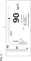
- the display device 22 is configured by, for example, a multi-information display 34 disposed within a meter.
- the display control device 20 is configured by, for example, a processor (not shown) composed of a computing device, a register for storing an instruction or information, a peripheral circuit, and the like, a memory (not shown) such as ROM (Read Only Memory), RAM (Random Access Memory), and an input/output interface (not shown).
- the display device 22 displays, for example, an SOC meter SM for displaying the state-of-charge of the driving battery and displays, when the EV priority mode is selected, the plurality of segments SG1 to SG3, which are lined up in a row, side by side with the SOC meter SM.
- the display of the SOC meter SM is not essential but optional.
- the plurality of segments SG1 to SG3 lined up in a row are configured by, for example, three segments SG1 to SG3 lined up on the left and right, but the number of plurality of segments SG1 to SG3 is not limited to three.
- the display control device 20 includes a number-of-charging-lights determination unit 36, a number-of-negative-pressure-lights determination unit 38, a number-of-output-lights determination unit 40, and a number-of-lights instruction unit 42.
- the plurality of segments SG1 to SG3 are assigned the state-of-charge ranging from the maximum state-of-charge of the driving battery to the charge threshold at which the engine starts, and the number-of-charging-lights determination unit 36 determines the number of lights, which corresponds to the state-of-charge of the driving battery (hereinafter "referred to as the number of charging lights”.
- the plurality of segments SG1 to SG3 are assigned the negative pressure ranging from the maximum negative pressure stored in the brake booster 14 to the negative pressure threshold at which the engine starts, and the number-of-negative-pressure-lights determination unit 38 determines the number of lights, which corresponds to the negative pressure of the brake booster 14 (hereinafter referred to as "the number of negative pressure lights").
- the plurality of segments SG1 to SG3 are assigned the requested output ranging from an output that can be output with the engine stopped to the output threshold at which the engine starts, and the number-of-output-lights determination unit 40 determines the number of lights, which corresponds to a difference between the output that can be output with the engine stopped and the requested output (hereinafter referred to as "the number of output lights").
- the number-of-lights instruction unit 42 instructs the display device 22 to light up the least number of segments SG1 to SG3 of the number of charging lights determined by the number-of-charging-lights determination unit 36, the number of negative pressure lights determined by the number-of-negative-pressure-lights determination unit 38, or the number of output lights determined by the number-of-output-lights determination unit 40.
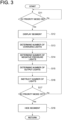
- step S11 when the EV priority mode is selected (EV priority mode is turned ON) by the EV priority mode selection device 10 (step S11: Yes), the plurality of segments SG1 to SG3 lined up in a row are displayed on the display device 22 at the instruction from the display control device 20 (step S12).
- the number-of-charging-lights determination unit 36 determines the number of charging lights, which corresponds to the state-of-charge of the driving battery, based on the state-of-charge of the driving battery detected by a state-of-charge detection unit step S13).
- the number-of-negative-pressure-lights determination unit 38 determines the number of negative pressure lights, which corresponds to the negative pressure of the brake booster 14, based on the negative pressure of the brake booster 14 detected by the negative pressure detection device 16 (step S14).
- the number-of-output-lights determination unit 40 calculates the difference between the output that can be output with the engine stopped and the user's requested output, and determines the number of output lights, which corresponds to this difference (step S15).
- the number-of-lights instruction unit 42 instructs the display device 22 to light up the least number of segments SG1 to SG3 of the number of charging lights determined by the number-of-charging-lights determination unit 36, the number of negative pressure lights determined by the number-of-negative-pressure-lights determination unit 38, or the number of output lights determined by the number-of-output-lights determination unit (step S16).
- the display device 22 lights up the number of segments SG1 to SG3 instructed by the number-of-lights instruction unit 42 (display control device 20).
- steps S13 to S17 are repeated until the EV priority mode is canceled (EV priority mode is turned OFF) by the EV priority mode selection device 10.
- step S17 when the EV priority mode is canceled (EV priority mode is turned OFF) by the EV priority mode selection device 10 (step S17: Yes), the plurality of segments SG1 to SG4 displayed on the display device 22 are hidden until the EV priority mode is selected again, at an instruction from the display control device 20 (step S18).
- the driving battery when the EV priority mode is selected and if EV driving is possible, the driving battery may be charged by a regenerative braking operation, but during EV driving, the number-of-charging-lights determination unit 36 may restrict an increase in the number of charging lights.
- an accelerator pedal operation may consume electricity charged in the driving battery, but during engine driving, the number-of-charging-lights determination unit 36 may restrict a decrease in the number of charging lights.
- a brake pedal operation may consume the negative pressure of the brake booster 14, but during EV driving, the number-of-negative-pressure-lights determination unit 38 may restrict a decrease in the number of negative pressure lights.
- the support system 1A since the least number of segments SG1 to SG3 of the number of charging lights, the number of negative pressure lights, or the number of output lights light up when the EV priority mode is selected, a user can continue EV driving by avoiding a sudden accelerator pedal operation while monitoring the number of segment lights (the number of lights turned off) and by prioritizing the regenerative braking operation over the brake pedal operation (support for continued EV driving).
- the display device 22 when the EV priority mode is selected, the display device 22 turns on an EV indicator EG at an instruction from the display control device 20 if EV driving is possible, whereas the display device 22 turns off the EV indicator EG at an instruction from the display control device 20 if EV driving is impossible.
- the EV indicator EG is, for example, bordered letters "EV”, and is configured such that the letters EV are filled in and illuminated when the EV indicator EG is turned on.
- the display device 22 may display text "EV driving in progress" at an instruction from the display control device 20 if EV driving is possible, whereas the display device 22 may display text "Standby" at an instruction from the display control device 20 if EV driving is impossible.
- the display device 22 may set a lighting color of the plurality of segments SG1 to SG3 lined up in a row to one lighting color (for example, green) at an instruction from the display control device 20 if EV driving is possible, whereas the display device 22 may set the lighting color of the plurality of segments SG1 to SG3 lined up in a row to another lighting color (for example, orange) at an instruction from the display control device 20 if EV driving is impossible.
- Other configurations are the same as those of the support system 1A according to Embodiment 1.
- the EV priority mode selection device 10 when the EV priority mode is selected (EV priority mode is turned ON) by the EV priority mode selection device 10 (step S21: Yes), the EV indicator EG is displayed on the display device 22 at the instruction from the display control device 20 (step S22).
- step S23 it is determined whether EV driving is possible (step S23). Then, if EV driving is possible (step S23: Yes), that is, the state-of-charge of the driving battery exceeds the charge threshold, the negative pressure of the brake booster 14 exceeds the negative pressure threshold, and the user's requested output is less than the output threshold, the EV indicator EG is turned on (step S24). On the other hand, if EV driving is impossible (step S23: No), that is, the state-of-charge of the driving battery is not greater than the charge threshold, the negative pressure of the brake booster 14 is not greater than the negative pressure threshold, or the user's requested output is not less than the output threshold, the EV indicator EG is turned off (step S25). Hereinafter, steps S23 to S26 are repeated until the EV priority mode is canceled (EV priority mode is turned OFF) by the EV priority mode selection device 10.
- step S26 when the EV priority mode is canceled (EV priority mode is turned OFF) by the EV priority mode selection device 10 (step S26: Yes), the EV indicator EG displayed on the display device 22 is hidden until the EV priority mode is selected again, at an instruction from the display control device 20 (step S27).
- Other operations are the same as those of the support system 1A according to Embodiment 1.
- the user can aware that EV driving is possible, by turning on the EV indicator EG, and the user can aware that EV driving is impossible (engine driving is performed), by turning off the EV indicator EG. Further, by turning off the EV indicator EG, the user can aware that the driving battery is charged with electricity generated by the engine due to return from engine driving to EV driving, and that the driving battery is charged by the regenerative braking. Whereby, in order to return from engine driving to EV driving, the user can be urged to avoid the sudden accelerator pedal operation and prioritize the regenerative braking operation over the brake pedal operation. Further, since the EV indicator EG transitions from off to on upon the return from engine driving to EV driving, the user can visually recognize a timing of returning from engine driving to EV driving.
- a support system 1C according to Embodiment 3 includes a charge mode selection device 44 for enabling selection of a charge mode where the driving battery is charged with the electricity generated by the engine.
- the charge mode selection device 44 is configured by, for example, the EV mode selector switch 26 disposed at the position adjacent to the selector lever 24.
- the number-of-lights instruction unit 42 instructs the display device 22 to light up the segments SG1 to SG3 of the number of charging lights determined by the number-of-charging-lights determination unit 36.
- Other configurations are the same as those of the support system 1A or 1B according to Embodiment 1 or 2.
- step A31: Yes when the charge mode is selected (charge mode is turned ON) by the charge mode selection device 44 (step A31: Yes), the plurality of segments SG1 to SG3 lined up in a row are displayed on the display device 22 at the instruction from the display control device 20 (step S32: Yes).
- the number-of-charging-lights determination unit 36 determines the number of charging lights, which corresponds to the state-of-charge of the driving battery, based on the state-of-charge of the driving battery detected by the state-of-charge detection unit (step S33).
- the number-of-lights instruction unit 42 instructs the display device 22 to turn on the number of charging lights determined by the number-of-charging-lights determination unit 36 (step S34).
- the display device 22 lights up the number of segments SG1 to SG3 instructed by the number-of-lights instruction unit 42 (display control device 20).
- steps S33 to S35 are repeated until the charge mode is canceled (charge mode is turned OFF) by the charge mode selection device 44 step S35: Yes).
- the plurality of segments SG1 to SG4 are configured by four segments SG1 to SG4 lined up in a row on the left and right, and include the segment SG4 for indicating full charge, which lights up if the state-of-charge of the driving battery is not less than predetermined full state-of-charge.
- the full state-of-charge is the state-of-charge at which the battery is considered fully charged, and if the state-of-charge is not greater than the maximum state-of-charge and the state-of-charge is assigned to three segments SG1 to SG3 from the left side among the four segments SG1 to SG4 lined up on the left and right, the state-of-charge is set which is at least not less than the minimum state-of-charge assigned to the third segment SG3.
- the segment SG4 for indicating full charge is the first segment SG4 from the right side when the four segments SG1 to SG4 are lined up in a row on the left and right.
- Other configurations are the same as those of any of the support systems 1A, 1B, 1C according to Embodiments 1 to 3.
- the segment SG4 for indicating full charge lights up at an instruction from the display control device 20.
- the segment SG4 for indicating full charge lights up at the instruction from the display control device 20.
- Other operations are the same as those of any of the support systems 1A, 1B, 1C according to Embodiments 1 to 3.
- the user can visually recognize whether the state-of-charge of the driving battery is not less than the full state-of-charge.
Landscapes
- Engineering & Computer Science (AREA)
- Transportation (AREA)
- Mechanical Engineering (AREA)
- Automation & Control Theory (AREA)
- Chemical & Material Sciences (AREA)
- Combustion & Propulsion (AREA)
- Human Computer Interaction (AREA)
- Power Engineering (AREA)
- Life Sciences & Earth Sciences (AREA)
- Sustainable Development (AREA)
- Sustainable Energy (AREA)
- Electric Propulsion And Braking For Vehicles (AREA)
- Hybrid Electric Vehicles (AREA)
Abstract
Description
- The present disclosure relates to a support system for supporting continued EV driving of a hybrid vehicle.
- Patent Document 1 discloses a vehicle control device for a vehicle powered by an internal combustion engine and a driving motor for generating a vehicle driving force by receiving power supply from a power storage device. The vehicle control device includes a detection part for detecting a remaining capacity of the power storage device, and a control part for selecting one of driving modes from a first mode for prioritizing motor driving using the driving motor with the internal combustion engine stopped and a second mode for forcibly prioritizing hybrid driving using the internal combustion engine and the driving motor regardless of the driving mode being selected, when the remaining capacity decreases below a first threshold.
- Further, the vehicle disclosed in Patent Document 1 is provided with a display device for displaying the remaining capacity. The display device displays which of a plurality of stages the remaining capacity is at, depending on the presence or absence of lighting of each of a plurality of segments corresponding to from a lower limit value to an upper limit value of the remaining capacity and capable of lighting.
- Patent Document 1:
JP5516027B - Meanwhile, if a user's requested output is not less than a predetermined threshold (output threshold), the internal combustion engine starts even if there is a surplus in the remaining capacity of the power storage device, making it impossible to continue motor driving (EV driving).
- Therefore, the continued EV driving cannot be supported (an EV driving distance cannot be extended) merely by displaying which of the plurality of stages the remaining capacity is at depending on the presence or absence of lighting of each of the plurality of segments corresponding to from the lower limit value to the upper limit value of the remaining capacity and capable of lighting.
- In view of the above, an object of at least one embodiment of the present invention is to provide a support system capable of supporting the continued EV driving.
-
- (1) A support system according to at least one embodiment of the present invention is a support system for continued EV driving of a hybrid vehicle which is allowed to select an EV priority mode where EV driving in which the hybrid vehicle travels with an engine stopped is prioritized over engine driving in which the hybrid vehicle travels with the engine in operation, and even when the EV priority mode is selected, starts the engine if state-of-charge of a driving battery is not greater than a predetermined charge threshold or a requested output of a user is not less than a predetermined output threshold, including: an EV priority mode selection device for selecting the EV priority mode; a state-of-charge detection device for detecting the state-of-charge; a requested output detection device for detecting the requested output; a display control device; and a display device for displaying a plurality of segments lined up in a row, at an instruction from the display control device, when the EV priority mode is selected. The display control device includes: a number-of-charging-lights determination unit for determining the number of charging lights, which corresponds to the state-of-charge, the state-of-charge ranging from maximum state-of-charge of the driving battery to the charge threshold being assigned to the plurality of segments such that the state-of-charge corresponds to the number of lights of the plurality of segments a number-of-output-lights determination unit for determining the number of output lights, which corresponds to a difference between the requested output and an output that can be output with the engine stopped, the requested output ranging from the output that can be output to the output threshold being assigned to the plurality of segments such that the difference corresponds to the number of lights of the plurality of segments; and a number-of-lights instruction unit for instructing the display device to light up the least number of segments of the number of charging lights or the number of output lights, when the EV priority mode is selected.
- With the above configuration (1), since the least number of segments of the number of charging lights or the number of output lights light up when the EV priority mode is selected, the user can continue EV driving by avoiding a sudden accelerator pedal operation while monitoring the number of segment lights (the number of lights turned off) and by prioritizing a regenerative braking operation over a brake pedal operation (support for continued EV driving).
- (2) In some embodiments, in the above configuration (1), the support system includes a charge mode selection device for enabling selection of a charge mode where the driving battery is charged with electricity generated by the engine. The number-of-lights instruction unit instructs the display device to light up the segments of the number of charging lights, when the charge mode is selected.
- With the above configuration (2), since the segments of the number of charging lights light up when the charge mode is selected, the user can visually recognize the state-of-charge of the driving battery.
- (3) In some embodiments, in the above configuration (1) or (2), when the EV priority mode is selected, the display device turns on an EV indicator at an instruction from the display control device if the EV driving is possible, whereas the display device turns off the EV indicator at an instruction from the display control device if the EV driving is impossible.
- With the above configuration (3), the user can aware that EV driving is possible, by turning on the EV indicator, and the user can aware that EV driving is impossible (engine driving is performed), by turning off the EV indicator. Further, by turning off the EV indicator, the user can aware that the driving battery is charged with electricity generated by the engine due to return from engine driving to EV driving, and that the driving battery is charged by the regenerative braking. Whereby, in order to return from engine driving to EV driving, the user can be urged to avoid the sudden accelerator pedal operation and prioritize the regenerative braking operation over the brake pedal operation. Further, since the EV indicator transitions from off to on upon the return from engine driving to EV driving, the user can visually recognize a timing of returning from engine driving to EV driving.
- (4) In some embodiments, in any one of the above configurations (1) to (3), the plurality of segments include a segment for indicating full charge, which lights up if the state-of-charge of the driving battery is not less than predetermined full state-of-charge.
- With the above configuration (4), the user can visually recognize whether the state-of-charge of the driving battery is not less than the full state-of-charge.
- (5) In some embodiments, in any one of the above configurations (1) to (5), the support system is a support system for starting the engine if a negative pressure of a brake booster is not greater than a predetermined negative pressure threshold, the support system including: a negative pressure detection device for detecting the negative pressure; and a number-of-negative-pressure-lights determination unit for determining the number of negative pressure lights, which corresponds to the negative pressure, the negative pressure ranging from a maximum negative pressure stored in the brake booster to the negative pressure threshold being assigned to the plurality of segments such that the negative pressure corresponds to the number of lights of the plurality of segments. The number-of-lights instruction unit instructs the display device to light up the least number of segments of the number of charging lights, the number of negative pressure lights, or the number of output lights, when the EV priority mode is selected.
- With the above configuration (5), since the least number of segments of the number of charging lights, the number of negative pressure lights, or the number of output lights light up when the EV priority mode is selected, the user can continue EV driving by avoiding the sudden accelerator pedal operation while monitoring the number of segment lights (the number of lights turned off) and by prioritizing the regenerative braking operation over the brake pedal operation.
- (6) In some embodiments, in any one of the above configurations (1) to (5), the display device displays an SOC meter for displaying the state-of-charge of the driving battery.
- With the above configuration (6), the user can visually recognize the state-of-charge of the driving battery and how much time is left before the engine starts.
- According to at least one embodiment of the present invention, it is possible to continue EV driving (support continued EV driving).
-
-
FIG. 1 is a block diagram schematically showing the configuration of a support system according to Embodiments 1 and 2. -
FIG. 2 is a view showing an example of an image displayed on a display device shown inFIG. 1 . -
FIG. 3 is a flowchart schematically showing an operation of the support system according to Embodiment 1. -
FIG. 4 is a flowchart schematically showing an operation of the support system according to Embodiment 2. -
FIG. 5 is a block diagram schematically showing the configuration of a support system according to Embodiments 3 and 4. -
FIG. 6 is a flowchart schematically showing an operation of the support system according to Embodiment 3. -
FIG. 7 is a view showing an example of an image displayed on the display device shown inFIG. 5 . - Some embodiments of the present invention will be described below with reference to the accompanying drawings. It is intended, however, that unless particularly identified, dimensions, materials, shapes, relative positions and the like of components described or shown in the drawings as the embodiments shall be interpreted as illustrative only and not intended to limit the scope of the present invention.
- A vehicle equipped with a support system according to Embodiment 1 is a hybrid vehicle powered by an engine and a motor, and is capable of engine driving in which the vehicle travels with the engine in operation and EV driving in which the vehicle travels with the engine stopped. The hybrid vehicle is, for example, a plug-in hybrid vehicle (PHEV, PHV) that can be charged from an external power source by external charging or that can supply external power to an external device, but is not limited to the plug-in hybrid vehicle.
- Further, the hybrid vehicle according to Embodiment 1 is allowed to select an EV priority mode where EV driving is prioritized over engine driving, and even when the EV priority mode is selected, is configured to start the engine if state-of-charge (SOC) of a driving battery is not greater than a predetermined charge threshold, a negative pressure of a brake booster is not greater than a predetermined negative pressure threshold, or a user's requested output is not less than a predetermined output threshold.
- Further, when the engine starts, the hybrid vehicle according to Embodiment 1 is configured to stop the engine if the state-of-charge of the driving battery is not less than a predetermined engine stop charge threshold, the negative pressure of the brake booster is not less than a predetermined engine stop negative pressure threshold, or the user's requested output is not greater than the output threshold. The engine stop charge threshold is optionally set within a range not greater than maximum state-of-charge of the driving battery and not less than the charge threshold, and the engine stop negative pressure threshold is optionally set within a range not less than a maximum negative pressure stored in the brake booster and not greater than the negative pressure threshold.
- A
support system 1A according to Embodiment 1 is a system for supporting continued EV driving and includes, as shown inFIG. 1 , an EV prioritymode selection device 10 for selecting the EV priority mode, a state-of-charge detection device 12 for detecting the state-of-charge of the driving battery, a negativepressure detection device 16 for detecting a negative pressure of abrake booster 14, a requestedoutput detection device 18 for detecting the user's requested output, adisplay control device 20, and adisplay device 22 for displaying a plurality of segments SG1 to SG3, which are lined up in a row, at an instruction from thedisplay control device 20 when the EV priority mode is selected. - The EV priority
mode selection device 10 is configured by, for example, an EVmode selector switch 26 disposed at a position adjacent to aselector lever 24, and the EV priority mode is selected by selecting the EV priority mode. The state-of-charge detection device 12 is configured by, for example, a battery management system (not shown) disposed in the driving battery. The negativepressure detection device 16 is configured by, for example, apressure sensor 28 disposed in thebrake booster 14. The requestedoutput detection device 18 is configured by, for example, an accelerator pedal position sensor 32 for detecting an amount of depression of anaccelerator pedal 30. Thedisplay device 22 is configured by, for example, amulti-information display 34 disposed within a meter. Thedisplay control device 20 is configured by, for example, a processor (not shown) composed of a computing device, a register for storing an instruction or information, a peripheral circuit, and the like, a memory (not shown) such as ROM (Read Only Memory), RAM (Random Access Memory), and an input/output interface (not shown). As shown inFIG. 2 , thedisplay device 22 displays, for example, an SOC meter SM for displaying the state-of-charge of the driving battery and displays, when the EV priority mode is selected, the plurality of segments SG1 to SG3, which are lined up in a row, side by side with the SOC meter SM. However, the display of the SOC meter SM is not essential but optional. Further, the plurality of segments SG1 to SG3 lined up in a row are configured by, for example, three segments SG1 to SG3 lined up on the left and right, but the number of plurality of segments SG1 to SG3 is not limited to three. - As shown in
FIG. 1 , thedisplay control device 20 includes a number-of-charging-lights determination unit 36, a number-of-negative-pressure-lights determination unit 38, a number-of-output-lights determination unit 40, and a number-of-lights instruction unit 42. - The plurality of segments SG1 to SG3 are assigned the state-of-charge ranging from the maximum state-of-charge of the driving battery to the charge threshold at which the engine starts, and the number-of-charging-
lights determination unit 36 determines the number of lights, which corresponds to the state-of-charge of the driving battery (hereinafter "referred to as the number of charging lights". - Further, the plurality of segments SG1 to SG3 are assigned the negative pressure ranging from the maximum negative pressure stored in the
brake booster 14 to the negative pressure threshold at which the engine starts, and the number-of-negative-pressure-lights determination unit 38 determines the number of lights, which corresponds to the negative pressure of the brake booster 14 (hereinafter referred to as "the number of negative pressure lights"). - Further, the plurality of segments SG1 to SG3 are assigned the requested output ranging from an output that can be output with the engine stopped to the output threshold at which the engine starts, and the number-of-output-
lights determination unit 40 determines the number of lights, which corresponds to a difference between the output that can be output with the engine stopped and the requested output (hereinafter referred to as "the number of output lights"). - When the EV priority mode is selected by the EV priority
mode selection device 10, the number-of-lights instruction unit 42 instructs thedisplay device 22 to light up the least number of segments SG1 to SG3 of the number of charging lights determined by the number-of-charging-lights determination unit 36, the number of negative pressure lights determined by the number-of-negative-pressure-lights determination unit 38, or the number of output lights determined by the number-of-output-lights determination unit 40. - As shown in
FIG. 3 , in thesupport system 1A according to Embodiment 1, when the EV priority mode is selected (EV priority mode is turned ON) by the EV priority mode selection device 10 (step S11: Yes), the plurality of segments SG1 to SG3 lined up in a row are displayed on thedisplay device 22 at the instruction from the display control device 20 (step S12). - Next, the number-of-charging-
lights determination unit 36 determines the number of charging lights, which corresponds to the state-of-charge of the driving battery, based on the state-of-charge of the driving battery detected by a state-of-charge detection unit step S13). Next, the number-of-negative-pressure-lights determination unit 38 determines the number of negative pressure lights, which corresponds to the negative pressure of thebrake booster 14, based on the negative pressure of thebrake booster 14 detected by the negative pressure detection device 16 (step S14). Next, based on the user's requested output detected by the requestedoutput detection device 18, the number-of-output-lights determination unit 40 calculates the difference between the output that can be output with the engine stopped and the user's requested output, and determines the number of output lights, which corresponds to this difference (step S15). - Next, the number-of-
lights instruction unit 42 instructs thedisplay device 22 to light up the least number of segments SG1 to SG3 of the number of charging lights determined by the number-of-charging-lights determination unit 36, the number of negative pressure lights determined by the number-of-negative-pressure-lights determination unit 38, or the number of output lights determined by the number-of-output-lights determination unit (step S16). Whereby, thedisplay device 22 lights up the number of segments SG1 to SG3 instructed by the number-of-lights instruction unit 42 (display control device 20). Hereinafter, steps S13 to S17 are repeated until the EV priority mode is canceled (EV priority mode is turned OFF) by the EV prioritymode selection device 10. - On the other hand, when the EV priority mode is canceled (EV priority mode is turned OFF) by the EV priority mode selection device 10 (step S17: Yes), the plurality of segments SG1 to SG4 displayed on the
display device 22 are hidden until the EV priority mode is selected again, at an instruction from the display control device 20 (step S18). - In the
support system 1A according to Embodiment 1, when the EV priority mode is selected and if EV driving is possible, the driving battery may be charged by a regenerative braking operation, but during EV driving, the number-of-charging-lights determination unit 36 may restrict an increase in the number of charging lights. Further, when the EV priority mode is selected and if EV driving is impossible (engine driving is performed), an accelerator pedal operation may consume electricity charged in the driving battery, but during engine driving, the number-of-charging-lights determination unit 36 may restrict a decrease in the number of charging lights. Likewise, a brake pedal operation may consume the negative pressure of thebrake booster 14, but during EV driving, the number-of-negative-pressure-lights determination unit 38 may restrict a decrease in the number of negative pressure lights. - With the
support system 1A according to Embodiment 1, since the least number of segments SG1 to SG3 of the number of charging lights, the number of negative pressure lights, or the number of output lights light up when the EV priority mode is selected, a user can continue EV driving by avoiding a sudden accelerator pedal operation while monitoring the number of segment lights (the number of lights turned off) and by prioritizing the regenerative braking operation over the brake pedal operation (support for continued EV driving). - In a
support system 1B (seeFIG. 1 ) according to Embodiment 2, when the EV priority mode is selected, thedisplay device 22 turns on an EV indicator EG at an instruction from thedisplay control device 20 if EV driving is possible, whereas thedisplay device 22 turns off the EV indicator EG at an instruction from thedisplay control device 20 if EV driving is impossible. As shown inFIG. 2 , the EV indicator EG is, for example, bordered letters "EV", and is configured such that the letters EV are filled in and illuminated when the EV indicator EG is turned on. Further, in thesupport system 1B according to Embodiment 2, when the EV priority mode mode is selected, thedisplay device 22 may display text "EV driving in progress" at an instruction from thedisplay control device 20 if EV driving is possible, whereas thedisplay device 22 may display text "Standby" at an instruction from thedisplay control device 20 if EV driving is impossible. Further, in thesupport system 1B according to Embodiment 2, when the EV priority mode mode is selected, thedisplay device 22 may set a lighting color of the plurality of segments SG1 to SG3 lined up in a row to one lighting color (for example, green) at an instruction from thedisplay control device 20 if EV driving is possible, whereas thedisplay device 22 may set the lighting color of the plurality of segments SG1 to SG3 lined up in a row to another lighting color (for example, orange) at an instruction from thedisplay control device 20 if EV driving is impossible. Other configurations are the same as those of thesupport system 1A according to Embodiment 1. - As shown in
FIG. 4 , in thesupport system 1B according to Embodiment 2, when the EV priority mode is selected (EV priority mode is turned ON) by the EV priority mode selection device 10 (step S21: Yes), the EV indicator EG is displayed on thedisplay device 22 at the instruction from the display control device 20 (step S22). - Next, it is determined whether EV driving is possible (step S23). Then, if EV driving is possible (step S23: Yes), that is, the state-of-charge of the driving battery exceeds the charge threshold, the negative pressure of the
brake booster 14 exceeds the negative pressure threshold, and the user's requested output is less than the output threshold, the EV indicator EG is turned on (step S24). On the other hand, if EV driving is impossible (step S23: No), that is, the state-of-charge of the driving battery is not greater than the charge threshold, the negative pressure of thebrake booster 14 is not greater than the negative pressure threshold, or the user's requested output is not less than the output threshold, the EV indicator EG is turned off (step S25). Hereinafter, steps S23 to S26 are repeated until the EV priority mode is canceled (EV priority mode is turned OFF) by the EV prioritymode selection device 10. - On the other hand, when the EV priority mode is canceled (EV priority mode is turned OFF) by the EV priority mode selection device 10 (step S26: Yes), the EV indicator EG displayed on the
display device 22 is hidden until the EV priority mode is selected again, at an instruction from the display control device 20 (step S27). Other operations are the same as those of thesupport system 1A according to Embodiment 1. - With the
support system 1B according to Embodiment 2, the user can aware that EV driving is possible, by turning on the EV indicator EG, and the user can aware that EV driving is impossible (engine driving is performed), by turning off the EV indicator EG. Further, by turning off the EV indicator EG, the user can aware that the driving battery is charged with electricity generated by the engine due to return from engine driving to EV driving, and that the driving battery is charged by the regenerative braking. Whereby, in order to return from engine driving to EV driving, the user can be urged to avoid the sudden accelerator pedal operation and prioritize the regenerative braking operation over the brake pedal operation. Further, since the EV indicator EG transitions from off to on upon the return from engine driving to EV driving, the user can visually recognize a timing of returning from engine driving to EV driving. - As shown in
FIG. 5 , asupport system 1C according to Embodiment 3 includes a chargemode selection device 44 for enabling selection of a charge mode where the driving battery is charged with the electricity generated by the engine. The chargemode selection device 44 is configured by, for example, the EVmode selector switch 26 disposed at the position adjacent to theselector lever 24. Further, in thesupport system 1C according to Embodiment 3, when the charge mode is selected by the chargemode selection device 44, the number-of-lights instruction unit 42 instructs thedisplay device 22 to light up the segments SG1 to SG3 of the number of charging lights determined by the number-of-charging-lights determination unit 36. Other configurations are the same as those of thesupport system - As shown in
FIG. 6 , in thesupport system 1C according to Embodiment 3, when the charge mode is selected (charge mode is turned ON) by the charge mode selection device 44 (step A31: Yes), the plurality of segments SG1 to SG3 lined up in a row are displayed on thedisplay device 22 at the instruction from the display control device 20 (step S32: Yes). - Next, the number-of-charging-
lights determination unit 36 determines the number of charging lights, which corresponds to the state-of-charge of the driving battery, based on the state-of-charge of the driving battery detected by the state-of-charge detection unit (step S33). Next, the number-of-lights instruction unit 42 instructs thedisplay device 22 to turn on the number of charging lights determined by the number-of-charging-lights determination unit 36 (step S34). Whereby, thedisplay device 22 lights up the number of segments SG1 to SG3 instructed by the number-of-lights instruction unit 42 (display control device 20). Hereinafter, steps S33 to S35 are repeated until the charge mode is canceled (charge mode is turned OFF) by the chargemode selection device 44 step S35: Yes). - On the other hand, when the charge mode is canceled (charge mode is turned OFF) by the charge
mode selection device 44, the plurality of segments SG1 to SG3 displayed on thedisplay device 22 are hidden until the charge mode is selected again, at an instruction from thedisplay control device 20. Other operations are the same as those of thesupport system - With the
support system 1C according to Embodiment 3, since the segments SG1 to SG3 of the number of charging lights light up when the charge mode is selected, the user can visually recognize the state-of-charge of the driving battery. - As shown in
FIG. 7 , in asupport system 1D (seeFIG. 5 ) according to Embodiment 4, the plurality of segments SG1 to SG4 are configured by four segments SG1 to SG4 lined up in a row on the left and right, and include the segment SG4 for indicating full charge, which lights up if the state-of-charge of the driving battery is not less than predetermined full state-of-charge. The full state-of-charge is the state-of-charge at which the battery is considered fully charged, and if the state-of-charge is not greater than the maximum state-of-charge and the state-of-charge is assigned to three segments SG1 to SG3 from the left side among the four segments SG1 to SG4 lined up on the left and right, the state-of-charge is set which is at least not less than the minimum state-of-charge assigned to the third segment SG3. The segment SG4 for indicating full charge is the first segment SG4 from the right side when the four segments SG1 to SG4 are lined up in a row on the left and right. Other configurations are the same as those of any of thesupport systems - In the
support system 1D according to Embodiment 4, for example, when the charge mode is selected by the chargemode selection device 44 and the state-of-charge of the driving battery, which is detected by the state-of-charge detection device 12, becomes not less than full charge due to the operation of the engine, the segment SG4 for indicating full charge lights up at an instruction from thedisplay control device 20. - Further, for example, when a hybrid vehicle is a plug-in hybrid vehicle, if external charging charges the driving battery from the external power source and the state-of-charge of the driving battery detected by the state-of-
charge detection device 12 becomes not less than full charge, the segment SG4 for indicating full charge lights up at the instruction from thedisplay control device 20. Other operations are the same as those of any of thesupport systems - With the
support system 1D according to Embodiment 4, the user can visually recognize whether the state-of-charge of the driving battery is not less than the full state-of-charge. -
- 1A, 1B, 1C, 1D Support system
- 10 EV priority mode selection device
- 12 State-of-charge detection device
- 14 Brake booster
- 16 Negative pressure detection device
- 18 Requested output detection device
- 20 Display control device
- 22 Display device
- 24 Selector lever
- 26 EV mode selector switch
- 28 Pressure sensor
- 30 Accelerator pedal
- 32 Accelerator pedal position sensor
- 34 Multi-information display
- 36 Number-of-charging-lights determination unit
- 38 Number-of-negative-pressure-lights determination unit
- 40 Number-of-output-lights decision unit
- 42 Number-of-lights instruction unit
- 44 Charge mode selection device
- SG1 to SG3, SG4 Segment
- SM SOC meter
- EG EV indicator
Claims (6)
- A support system for supporting continued EV driving of a hybrid vehicle which is allowed to select an EV priority mode where EV driving in which the hybrid vehicle travels with an engine stopped is prioritized over engine driving in which the hybrid vehicle travels with the engine in operation, and
even when the EV priority mode is selected, starts the engine if state-of-charge of a driving battery is not greater than a predetermined charge threshold or a requested output of a user is not less than a predetermined output threshold, comprising:an EV priority mode selection device for selecting the EV priority mode;a state-of-charge detection device for detecting the state-of-charge;a requested output detection device for detecting the requested output;a display control device; anda display device for displaying a plurality of segments lined up in a row, at an instruction from the display control device, when the EV priority mode is selected,wherein the display control device includes:a number-of-charging-lights determination unit for determining the number of charging lights, which corresponds to the state-of-charge, the state-of-charge ranging from maximum state-of-charge of the driving battery to the charge threshold being assigned to the plurality of segments such that the state-of-charge corresponds to the number of lights of the plurality of segments;a number-of-output-lights determination unit for determining the number of output lights, which corresponds to a difference between the requested output and an output that can be output with the engine stopped, the requested output ranging from the output that can be output to the output threshold being assigned to the plurality of segments such that the difference corresponds to the number of lights of the plurality of segments; anda number-of-lights instruction unit for instructing the display device to light up the least number of segments of the number of charging lights or the number of output lights, when the EV priority mode is selected. - The support system according to claim 1, comprising:a charge mode selection device for enabling selection of a charge mode where the driving battery is charged with electricity generated by the engine,wherein the number-of-lights instruction unit instructs the display device to light up the segments of the number of charging lights, when the charge mode is selected.
- The support system according to claim 1,
wherein, when the EV priority mode is selected, the display device turns on an EV indicator at an instruction from the display control device if the EV driving is possible, whereas the display device turns off the EV indicator at an instruction from the display control device if the EV driving is impossible. - The support system according to claim 1,
wherein the plurality of segments include a segment for indicating full charge, which lights up if the state-of-charge of the driving battery is not less than predetermined full state-of-charge. - The support system according to claim 1,
wherein the support system is a support system for starting the engine if a negative pressure of a brake booster is not greater than a predetermined negative pressure threshold, the support system comprising:a negative pressure detection device for detecting the negative pressure; anda number-of-negative-pressure-lights determination unit for determining the number of negative pressure lights, which corresponds to the negative pressure, the negative pressure ranging from a maximum negative pressure stored in the brake booster to the negative pressure threshold being assigned to the plurality of segments such that the negative pressure corresponds to the number of lights of the plurality of segments, andwherein the number-of-lights instruction unit instructs the display device to light up the least number of segments of the number of charging lights, the number of negative pressure lights, or the number of output lights, when the EV priority mode is selected. - The support system according to any one of claims 1 to 5,
wherein the display device displays an SOC meter for displaying the state-of-charge of the driving battery.
Applications Claiming Priority (2)
| Application Number | Priority Date | Filing Date | Title |
|---|---|---|---|
| JP2022021209 | 2022-02-15 | ||
| PCT/JP2023/002612 WO2023157608A1 (en) | 2022-02-15 | 2023-01-27 | Support system |
Publications (2)
| Publication Number | Publication Date |
|---|---|
| EP4480772A1 true EP4480772A1 (en) | 2024-12-25 |
| EP4480772A4 EP4480772A4 (en) | 2025-08-20 |
Family
ID=87578369
Family Applications (1)
| Application Number | Title | Priority Date | Filing Date |
|---|---|---|---|
| EP23756136.0A Pending EP4480772A4 (en) | 2022-02-15 | 2023-01-27 | SUPPORT SYSTEM |
Country Status (5)
| Country | Link |
|---|---|
| US (1) | US12528353B2 (en) |
| EP (1) | EP4480772A4 (en) |
| JP (1) | JP7616473B2 (en) |
| CN (1) | CN118660822A (en) |
| WO (1) | WO2023157608A1 (en) |
Families Citing this family (1)
| Publication number | Priority date | Publication date | Assignee | Title |
|---|---|---|---|---|
| US12589649B2 (en) * | 2023-10-31 | 2026-03-31 | GM Global Technology Operations LLC | Haptic feedback systems for vehicle acceleration pedals |
Family Cites Families (20)
| Publication number | Priority date | Publication date | Assignee | Title |
|---|---|---|---|---|
| JP3331717B2 (en) * | 1993-12-25 | 2002-10-07 | 株式会社デンソー | Full-charge request output device for electric vehicles |
| JP2006290182A (en) | 2005-04-12 | 2006-10-26 | Nissan Motor Co Ltd | Driving state display device for hybrid vehicle |
| JP4155321B2 (en) | 2006-09-25 | 2008-09-24 | トヨタ自動車株式会社 | Hybrid vehicle display device, hybrid vehicle, and hybrid vehicle display method |
| US7671567B2 (en) * | 2007-06-15 | 2010-03-02 | Tesla Motors, Inc. | Multi-mode charging system for an electric vehicle |
| JP4341704B2 (en) * | 2007-07-12 | 2009-10-07 | トヨタ自動車株式会社 | Hybrid vehicle and control method of hybrid vehicle |
| US9764632B2 (en) * | 2010-01-07 | 2017-09-19 | Ford Global Technologies, Llc | Plug-in hybrid electric vehicle battery state of charge hold function and energy management |
| JP5516027B2 (en) | 2010-04-28 | 2014-06-11 | トヨタ自動車株式会社 | Vehicle control device |
| CN103260932B (en) * | 2010-10-14 | 2016-05-18 | 丰田自动车株式会社 | The display system of electric vehicle and possess the electric vehicle of this display system |
| DE102011112643B4 (en) * | 2011-09-07 | 2020-11-05 | Volkswagen Aktiengesellschaft | Display device for a hybrid vehicle and method for display and hybrid vehicle |
| JP5887959B2 (en) | 2012-01-27 | 2016-03-16 | トヨタ自動車株式会社 | Display device for hybrid vehicle |
| JP2014113830A (en) | 2012-12-06 | 2014-06-26 | Denso Corp | Vehicular drive force control device |
| DE112013007563T5 (en) * | 2013-10-30 | 2016-07-14 | Honda Motor Co., Ltd. | Device for controlling / controlling a pedal application force |
| JP6185945B2 (en) * | 2015-02-23 | 2017-08-23 | 株式会社Subaru | SOC display device for hybrid vehicle |
| JP6432415B2 (en) * | 2015-03-26 | 2018-12-05 | スズキ株式会社 | Battery remaining capacity display device |
| JP6693245B2 (en) * | 2016-04-08 | 2020-05-13 | 三菱自動車工業株式会社 | Driving support device |
| JP2019170136A (en) | 2018-03-26 | 2019-10-03 | 三菱自動車工業株式会社 | Charge control device |
| JP7149230B2 (en) * | 2019-06-26 | 2022-10-06 | 本田技研工業株式会社 | Vehicle system and hybrid vehicle |
| JP7444087B2 (en) * | 2021-01-21 | 2024-03-06 | トヨタ自動車株式会社 | Hybrid vehicle control device |
| JP7375779B2 (en) * | 2021-01-21 | 2023-11-08 | トヨタ自動車株式会社 | Hybrid vehicle control device |
| JP7375780B2 (en) * | 2021-01-21 | 2023-11-08 | トヨタ自動車株式会社 | Hybrid vehicle control device |
-
2023
- 2023-01-27 EP EP23756136.0A patent/EP4480772A4/en active Pending
- 2023-01-27 US US18/723,929 patent/US12528353B2/en active Active
- 2023-01-27 CN CN202380019777.XA patent/CN118660822A/en active Pending
- 2023-01-27 JP JP2024501062A patent/JP7616473B2/en active Active
- 2023-01-27 WO PCT/JP2023/002612 patent/WO2023157608A1/en not_active Ceased
Also Published As
| Publication number | Publication date |
|---|---|
| JP7616473B2 (en) | 2025-01-17 |
| US20250058630A1 (en) | 2025-02-20 |
| EP4480772A4 (en) | 2025-08-20 |
| WO2023157608A1 (en) | 2023-08-24 |
| US12528353B2 (en) | 2026-01-20 |
| CN118660822A (en) | 2024-09-17 |
| JPWO2023157608A1 (en) | 2023-08-24 |
Similar Documents
| Publication | Publication Date | Title |
|---|---|---|
| CN111954964B (en) | Optimization system and optimization method | |
| JP5429197B2 (en) | Vehicle control device | |
| US8751079B2 (en) | Method and device for controlling a battery pulse heating mode of a traction battery of a hybrid vehicle | |
| US9327603B2 (en) | Vehicle equipped with regenerative generator | |
| EP2168826B1 (en) | Hybrid vehicle | |
| US20170008408A1 (en) | Method for controlling output of low voltage dc-dc converter in vehicle and low voltage dc-dc converter of vehicle | |
| EP2792551A1 (en) | Power consumption prediction device, vehicle control device, vehicle, power consumption prediction method, and vehicle control method | |
| EP2442074A1 (en) | Electrically driven vehicle | |
| JP2004147460A (en) | Power control device for vehicle | |
| US11440409B2 (en) | Vehicle system and hybrid vehicle | |
| US20230064386A1 (en) | Battery operation mode display device for vehicle | |
| EP4480772A1 (en) | Support system | |
| CN107110659A (en) | Driving assistance method and system and the vehicle with driving assistance method and system | |
| US20200369174A1 (en) | Influence degree display device, influence degree display method, and storage medium | |
| JP6217908B2 (en) | Electric drive system for electric drive | |
| JP6145998B2 (en) | Control device for hybrid vehicle | |
| KR102336723B1 (en) | Apparatus and method for managing battery | |
| JP5444727B2 (en) | VEHICLE CHARGE CONTROL DEVICE AND VEHICLE CHARGE CONTROL METHOD | |
| US20230373343A1 (en) | Vehicle and control method thereof | |
| JP2006256397A (en) | Vehicle instrument | |
| JP5922427B2 (en) | vehicle | |
| US20190389327A1 (en) | Charging control apparatus, charging control method, and storage medium | |
| EP2823984B1 (en) | Electric vehicle and method for controlling electric vehicle | |
| JP2012066621A (en) | Drive mode display device for hybrid vehicle | |
| US20230058534A1 (en) | Vehicle battery control device |
Legal Events
| Date | Code | Title | Description |
|---|---|---|---|
| STAA | Information on the status of an ep patent application or granted ep patent |
Free format text: STATUS: THE INTERNATIONAL PUBLICATION HAS BEEN MADE |
|
| PUAI | Public reference made under article 153(3) epc to a published international application that has entered the european phase |
Free format text: ORIGINAL CODE: 0009012 |
|
| STAA | Information on the status of an ep patent application or granted ep patent |
Free format text: STATUS: REQUEST FOR EXAMINATION WAS MADE |
|
| 17P | Request for examination filed |
Effective date: 20240724 |
|
| AK | Designated contracting states |
Kind code of ref document: A1 Designated state(s): AL AT BE BG CH CY CZ DE DK EE ES FI FR GB GR HR HU IE IS IT LI LT LU LV MC ME MK MT NL NO PL PT RO RS SE SI SK SM TR |
|
| DAV | Request for validation of the european patent (deleted) | ||
| DAX | Request for extension of the european patent (deleted) | ||
| REG | Reference to a national code |
Ref country code: DE Ref legal event code: R079 Free format text: PREVIOUS MAIN CLASS: B60W0010000000 Ipc: B60L0050160000 |
|
| A4 | Supplementary search report drawn up and despatched |
Effective date: 20250721 |
|
| RIC1 | Information provided on ipc code assigned before grant |
Ipc: B60L 50/16 20190101AFI20250715BHEP Ipc: B60L 50/60 20190101ALI20250715BHEP Ipc: B60L 58/12 20190101ALI20250715BHEP Ipc: B60W 20/00 20160101ALI20250715BHEP Ipc: B60K 35/22 20240101ALI20250715BHEP Ipc: B60K 35/28 20240101ALI20250715BHEP Ipc: B60K 35/29 20240101ALI20250715BHEP Ipc: B60K 35/81 20240101ALI20250715BHEP Ipc: B60T 17/02 20060101ALI20250715BHEP Ipc: B60T 17/22 20060101ALI20250715BHEP Ipc: B60W 10/00 20060101ALI20250715BHEP Ipc: B60W 50/14 20200101ALI20250715BHEP Ipc: B60W 10/06 20060101ALI20250715BHEP Ipc: B60W 10/08 20060101ALI20250715BHEP Ipc: B60W 30/182 20200101ALI20250715BHEP Ipc: B60W 50/08 20200101ALI20250715BHEP |